Tranzeo Wireless Technologies GNADX2NT4 WIRELESS MESH ROUTER User Manual USERS MANUAL
Tranzeo Wireless Technologies, Inc WIRELESS MESH ROUTER USERS MANUAL
UserManual.wiki
>
Tranzeo Wireless Technologies
>
GNADX2NT4 User Manual
USERS MANUAL
Navigation menu
Upload a User Manual
Namespaces
Wiki Guide
HTML
PDF
Info
Views
User Manual
Discussion / Help
Navigation
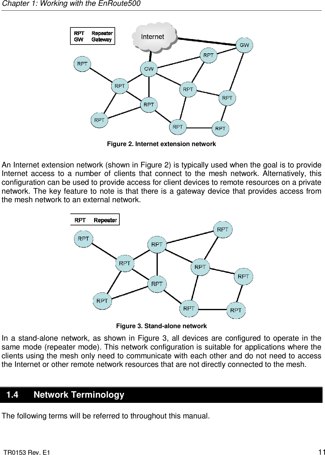
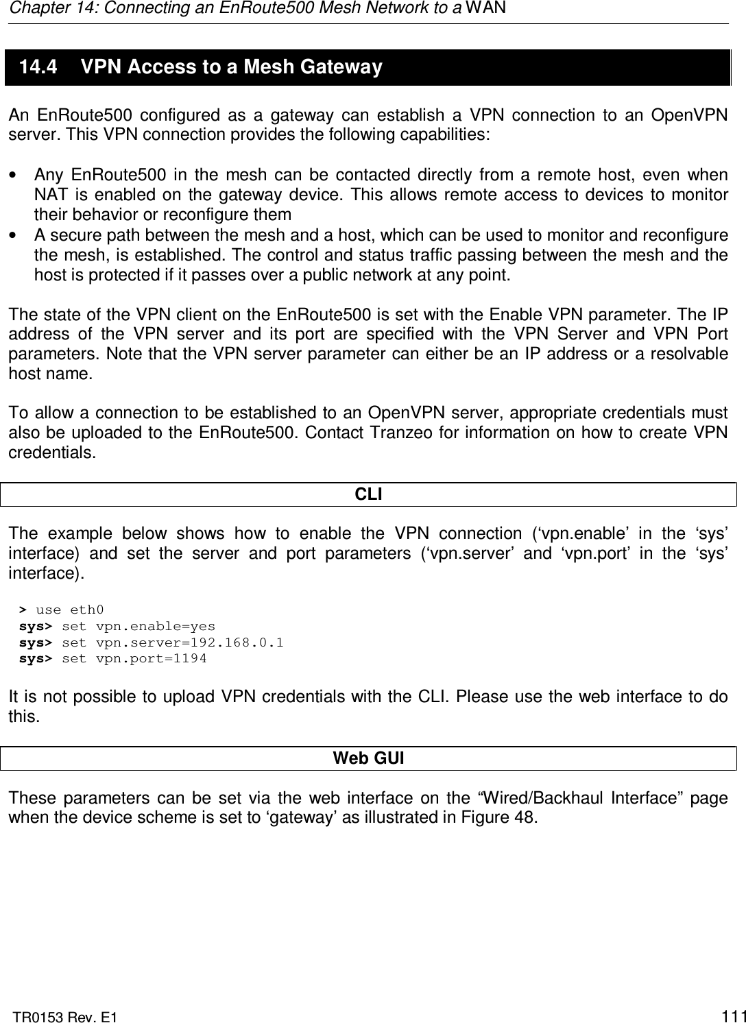
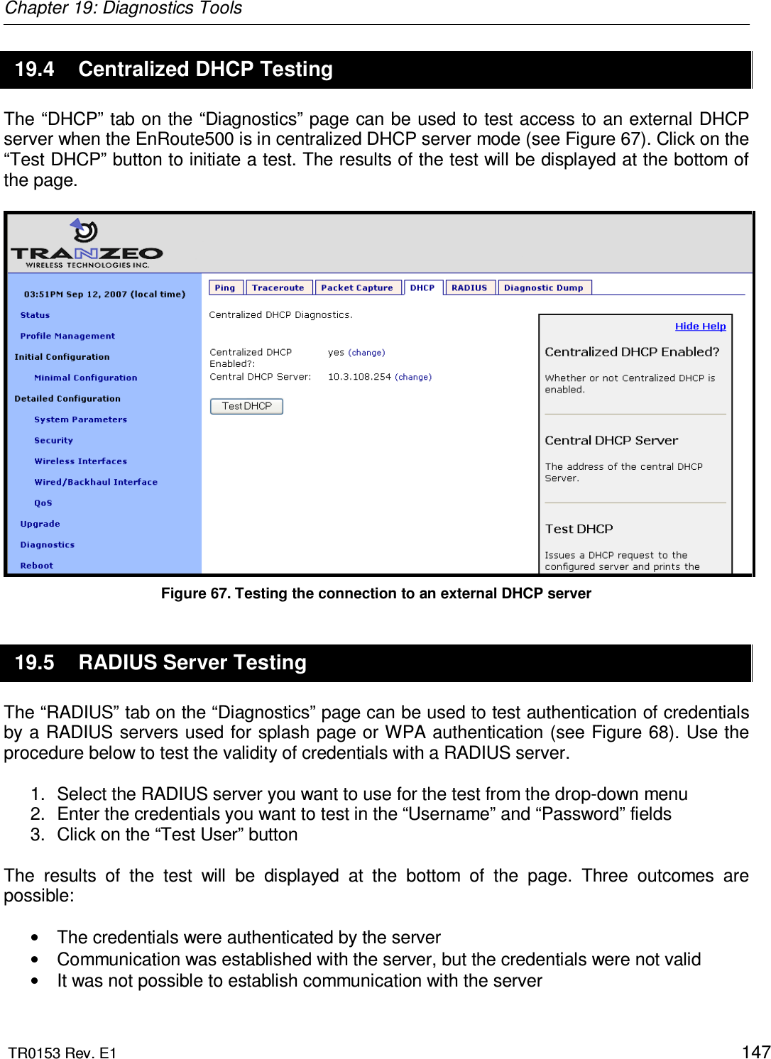
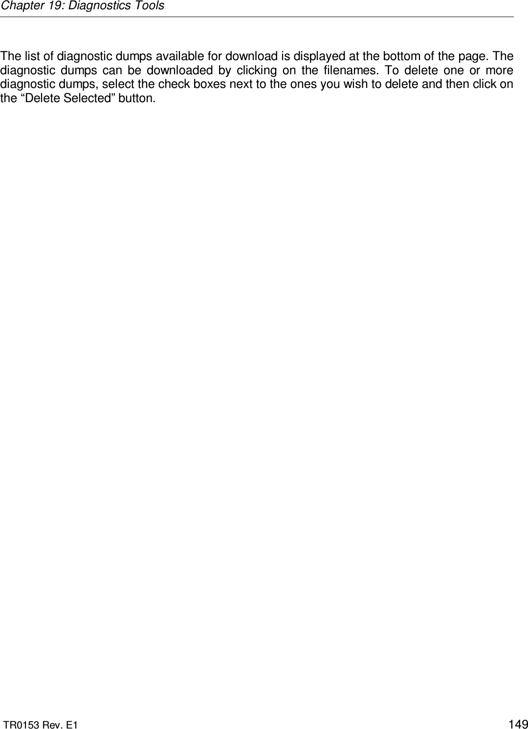
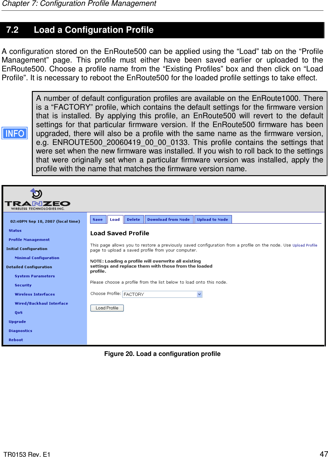
![Chapter 4: Using the Command Line Interface TR0153 Rev. E1 26 4.4.3 Searching the Command History The command history can be searched by pressing Ctrl+R and entering a search string. The most recently executed command that matches the string entered will be displayed. Press ‘Enter’ to execute that command. 4.4.4 Executing a Previous Command By using the up and down arrow keys you can select previously executed commands. When you find the command you wish to execute, you can either edit it or press ‘Return’ to execute it. 4.5 CLI Commands The usage of all CLI commands is explained in the following subsections. The command syntax used is command <mandatory argument> command [optional argument] 4.5.1 ‘?’ command Syntax ? Description Pressing ‘?’ at any time in the CLI will display a help menu that provides an overview of the commands that are described in this section. It is not necessary to press ‘Enter’ after pressing ‘?’. 4.5.2 ‘whoami’ command Syntax whoami Description Displays the name of the user you are logged in as.](https://usermanual.wiki/Tranzeo-Wireless-Technologies/GNADX2NT4/User-Guide-1467570-Page-26.png)
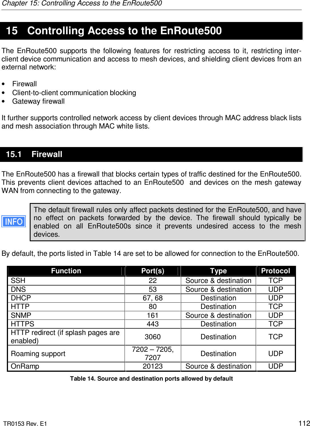
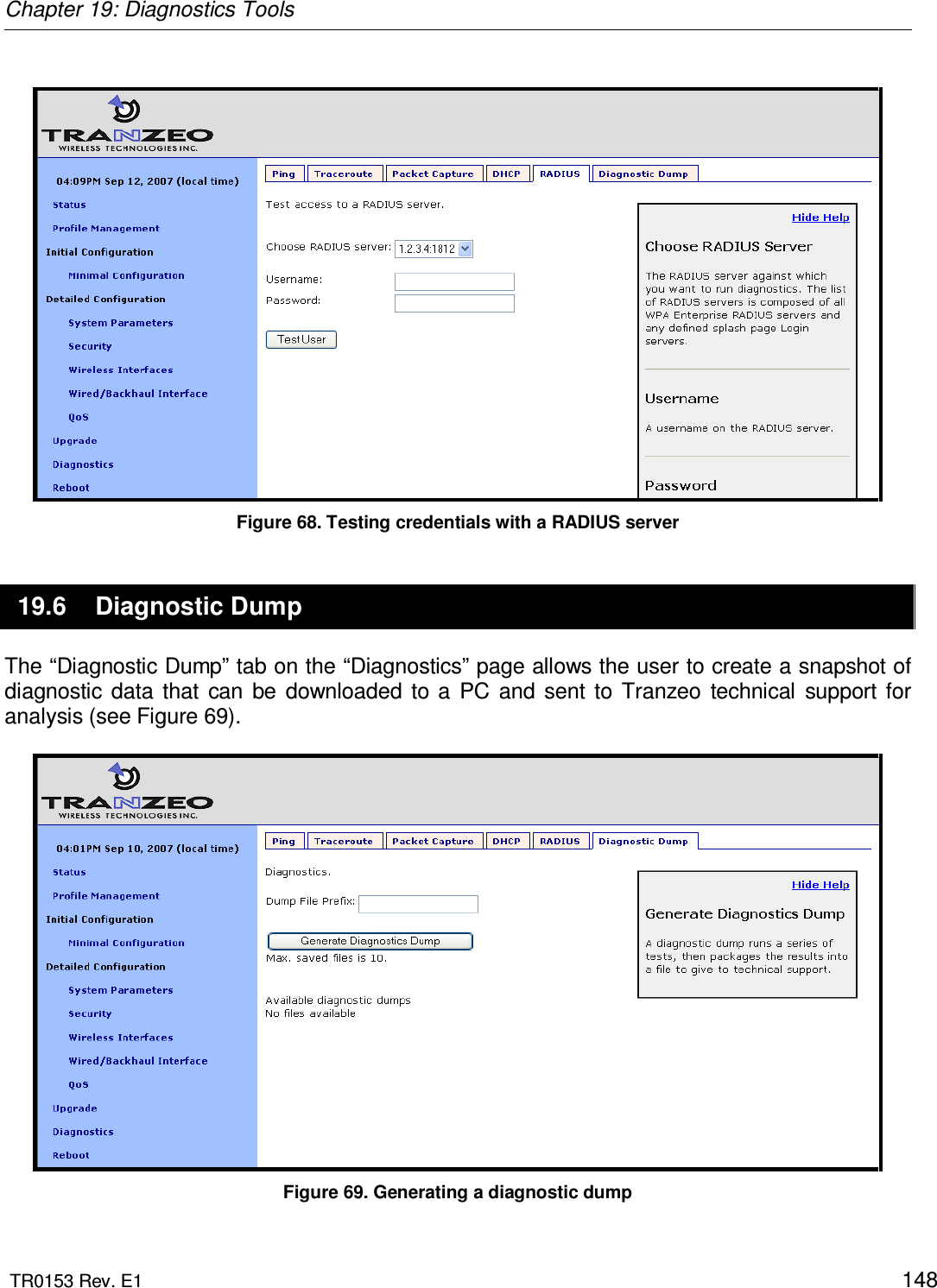
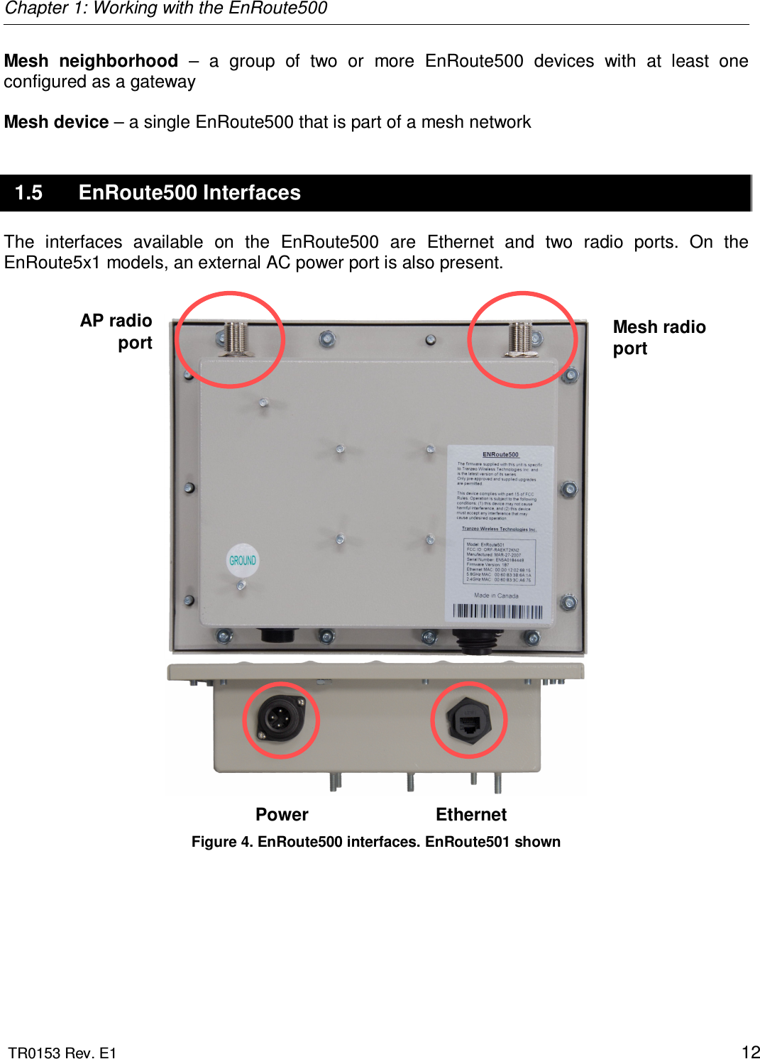
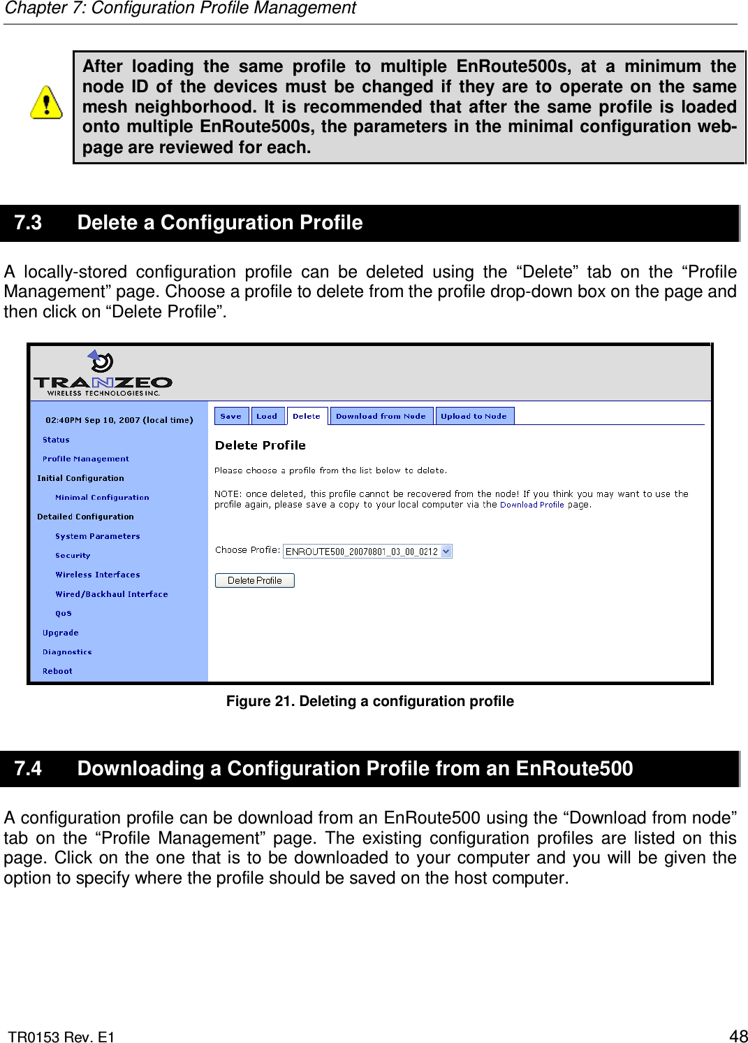
![Chapter 4: Using the Command Line Interface TR0153 Rev. E1 27 4.5.3 ‘help’ command Syntax help [command|parameter] where the optional argument is either one of the CLI commands (“[command]”) or a parameter in the currently selected interface (“[parameter]”). Description When no argument follows the help command, a help menu showing a list of available commands is displayed. When a command is supplied as the argument, a help message for that particular command is displayed. When a parameter in the current interface is specified as the argument, help information for it is displayed. Example help get will display the help information for the ‘get’ command. With the ‘sys’ interface selected sys> help scheme displays help information about that ‘scheme’ parameter, as shown below scheme : wireless node type 4.5.4 ‘show’ command Syntax show Description Displays all available interfaces. An interface in this list can be selected with the ‘use’ command.](https://usermanual.wiki/Tranzeo-Wireless-Technologies/GNADX2NT4/User-Guide-1467570-Page-27.png)

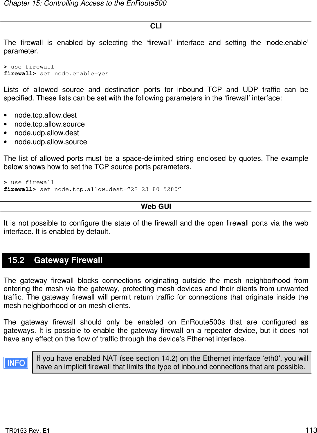
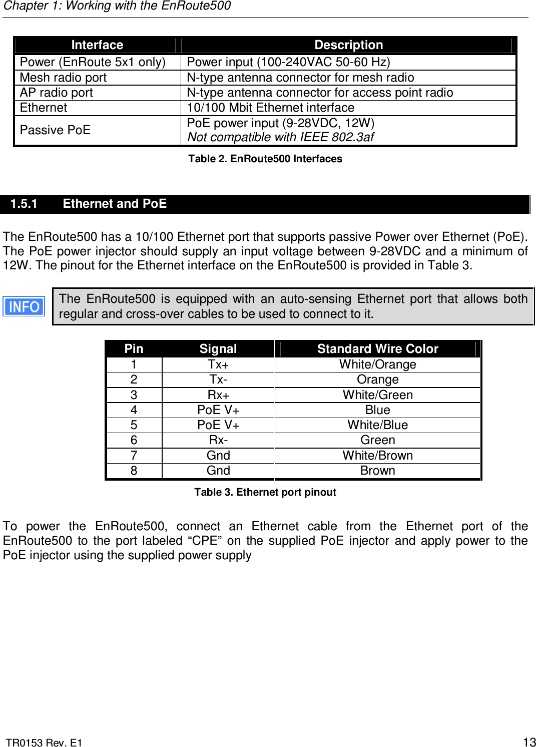
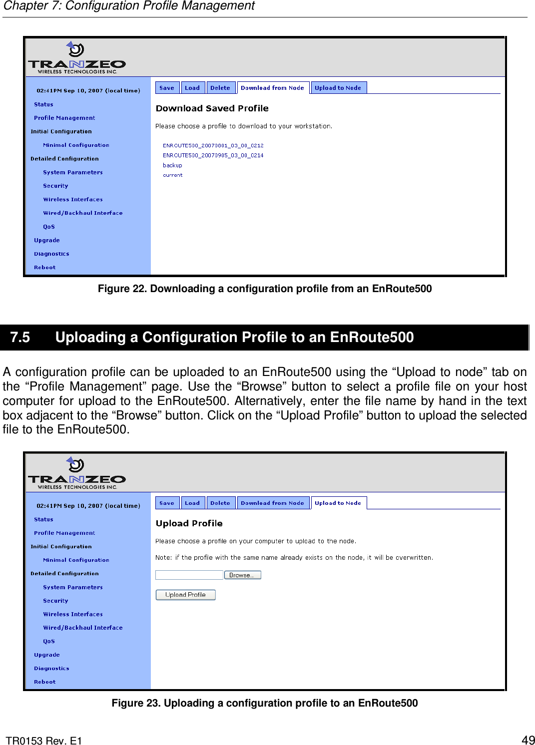
![Chapter 4: Using the Command Line Interface TR0153 Rev. E1 32 4.5.10 ‘ifconfig’ command Syntax ifconfig <eth0|wlan[0-4]> Description Displays information, such as IP address and MAC address, for the specified network interface. Example ifconfig wlan1 will display wlan1 Link encap:Ethernet HWaddr 00:15:6D:52:01:FD inet addr:10.2.10.1 Bcast:172.29.255.255 Mask:255.255.0.0 UP BROADCAST RUNNING MULTICAST MTU:1500 Metric:1 RX packets:0 errors:0 dropped:0 overruns:0 frame:0 TX packets:2434 errors:0 dropped:0 overruns:0 carrier:0 collisions:0 txqueuelen:0 RX bytes:0 (0.0 b) TX bytes:233128 (227.6 Kb) 4.5.11 ‘route’ command Syntax route Description Displays the current route table. 4.5.12 ‘clear’ command Syntax clear Description Clears the screen](https://usermanual.wiki/Tranzeo-Wireless-Technologies/GNADX2NT4/User-Guide-1467570-Page-32.png)
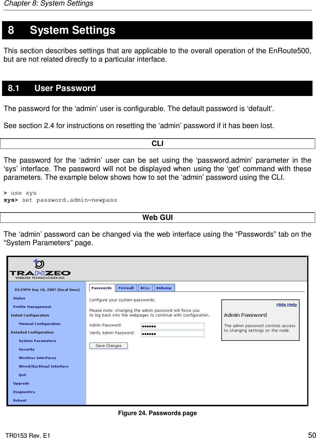
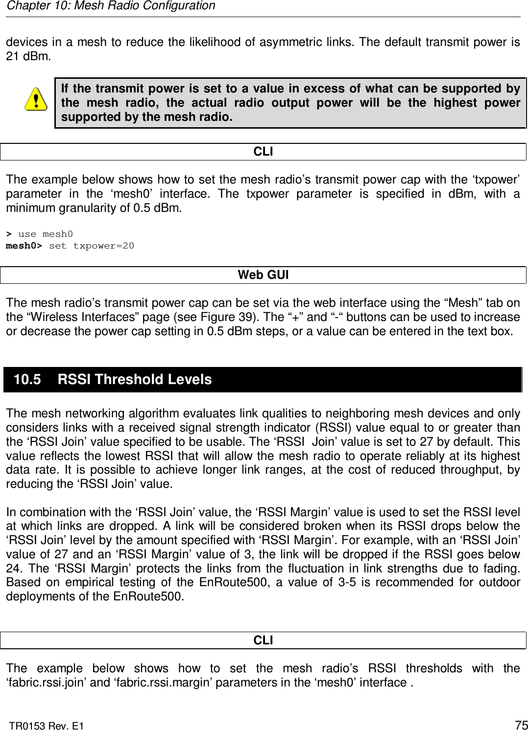
![Chapter 10: Mesh Radio Configuration TR0153 Rev. E1 76 > use mesh0 mesh0> set fabric.rssi.join=27 > use mesh0 mesh0> set fabric.rssi.margin=3 Web GUI The mesh radio RSSI thresholds can be set via the web interface using the “Mesh” tab on the “Wireless Interfaces” page (see Figure 39). 10.6 IP Configuration The IP address, broadcast address, and netmask associated with the mesh radio interface can be viewed through the CLI and web interfaces. It is not possible to directly set these values though. To change the mesh interface IP settings, mesh prefix and the node and mesh ID settings must be changed (see sections 8.3 and 8.5). CLI In the CLI, the mesh IP settings can be viewed with > use mesh0 mesh0> get ip.address ip.address = 172.29.2.4 [read-only] mesh0> get ip.broadcast ip.broadcast = 172.29.255.255 [read-only] mesh0> get ip.gateway ip.gateway = [read-only] mesh0> get ip.netmask ip.netmask = 255.255.0.0 [read-only] Web GUI The mesh radio IP settings are available through the web interface on the “Config Overview” tab on the “Status’ page under the heading “Wireless FabricTM (mesh)”. 10.7 Neighbor Status For a mesh device to be considered a neighbor, a minimum SNR threshold must be met. The minimum SNR required for a link to be established and maintained are set with the ‘RSSI Join’ and ‘RSSI Margin’ parameters (see section 10.5). See section 6.2.1 for how to access information, including RSSI and SNR, about mesh neighbors.](https://usermanual.wiki/Tranzeo-Wireless-Technologies/GNADX2NT4/User-Guide-1467570-Page-76.png)
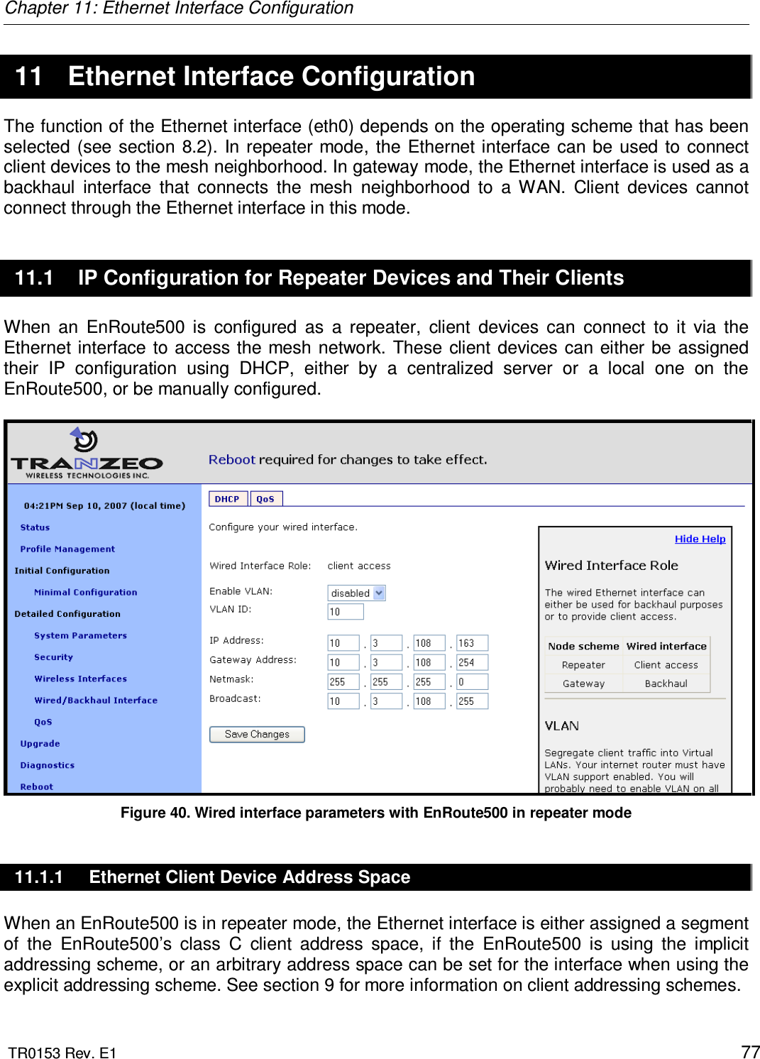
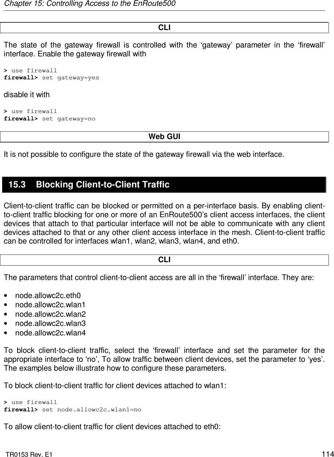
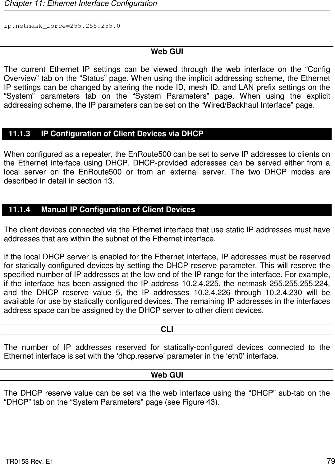
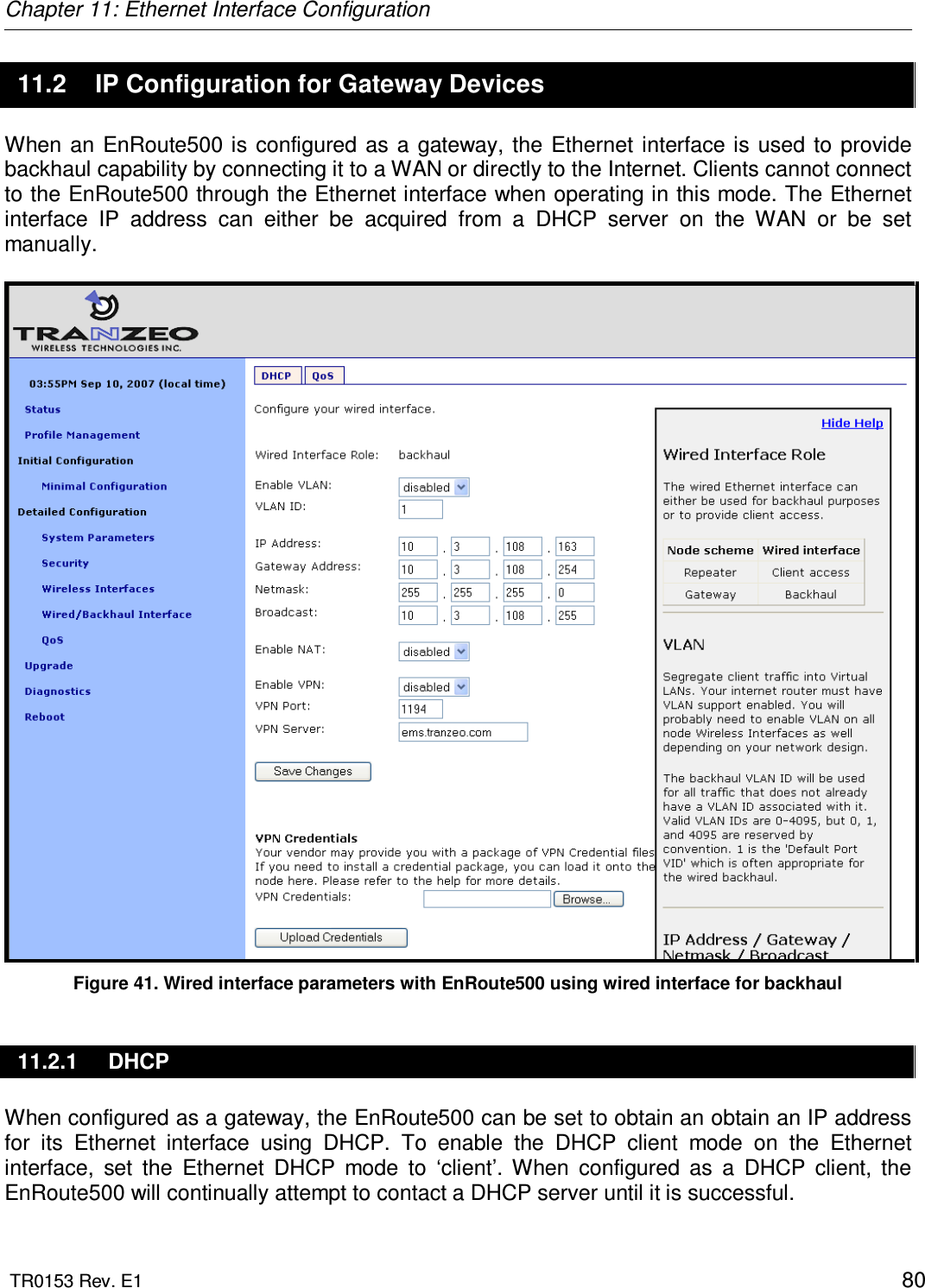
![Chapter 11: Ethernet Interface Configuration TR0153 Rev. E1 78 11.1.2 Ethernet Interface IP Configuration The EnRoute500’s Ethernet interface IP configuration can be changed directly when it is in repeater mode and using the explicit addressing scheme. It should not be changed directly when the device is in repeater mode and using the implicit addressing scheme. When an EnRoute500 is configured to use the implicit addressing scheme, set the IP address to the desired value by modifying the node ID, mesh ID, and LAN prefix parameters (see sections 8.3 and 9.1.1). Set the netmask by changing the client address space segments as described in 9.1.2. When using the explicit addressing scheme, the IP configuration can be set directly. Care must be taken to avoid using the same or overlapping address spaces on different devices in a mesh neighborhood. CLI You can view the IP settings for the Ethernet interface with the ‘ip.*’ parameters in the ‘eth0’ interface as shown in the example below. > use eth0 eth0> get ip.* ip.address = 10.2.4.225 [read-only] ip.address_force = ip.broadcast = 10.2.4.255 [read-only] ip.broadcast_force = ip.gateway = [read-only] ip.gateway_force = ip.netmask = 255.255.255.0 [read-only] ip.netmask_force = ip.implicit.size.actual = [read-only] ip.implicit.size.requested = 31 ip.implicit.start.actual = [read-only] ip.implicit.start.requested = 225 When an EnRoute500 is in repeater mode and using the implicit addressing scheme, the Ethernet IP settings can be changed by altering the ‘id.node’, ‘id.mesh’, and ‘id.lanprefix’ parameters in the ‘sys’ interface and the ‘ip.implicit.start.requested’ parameter in the ‘eth0’ interface. When an EnRoute500 is configured as a repeater, but is using the explicit addressing scheme, the IP address, netmask, gateway address, and broadcast address can be set using the ‘ip.address_force’, ‘ip.netmask_force’, ‘ip.gateway_force’, and ‘ip.broadcast_force’ parameters in the ‘eth0’ interface as shown in the example below. > use eth0 eth0> set ip.address_force= 10.12.7.1 ip.broadcast_force= 10.12.7.255 ip.gateway_force=](https://usermanual.wiki/Tranzeo-Wireless-Technologies/GNADX2NT4/User-Guide-1467570-Page-78.png)
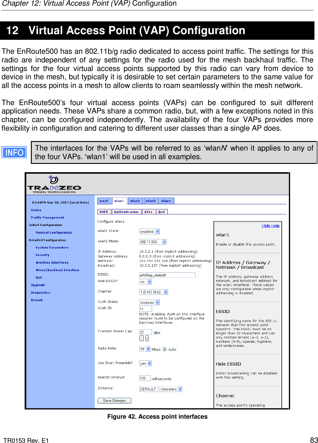
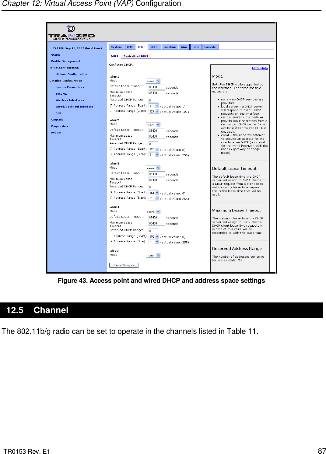
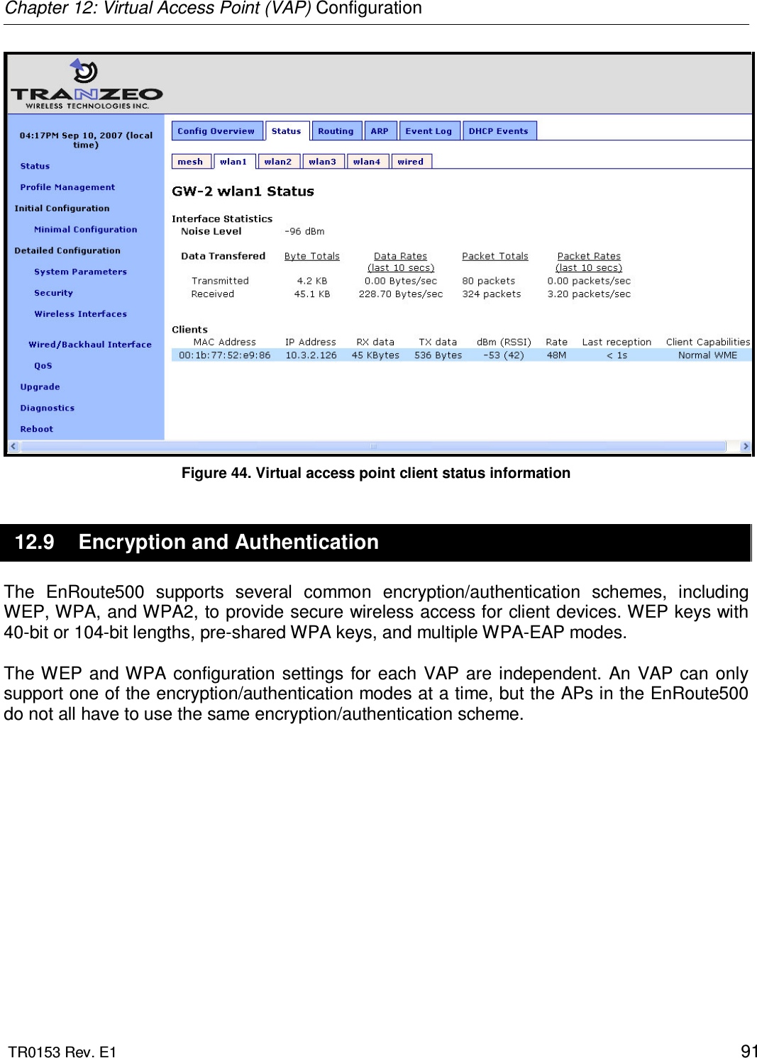
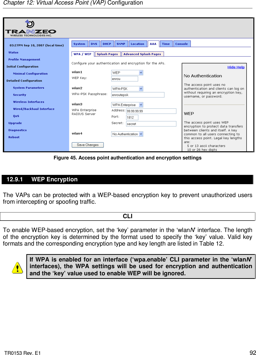
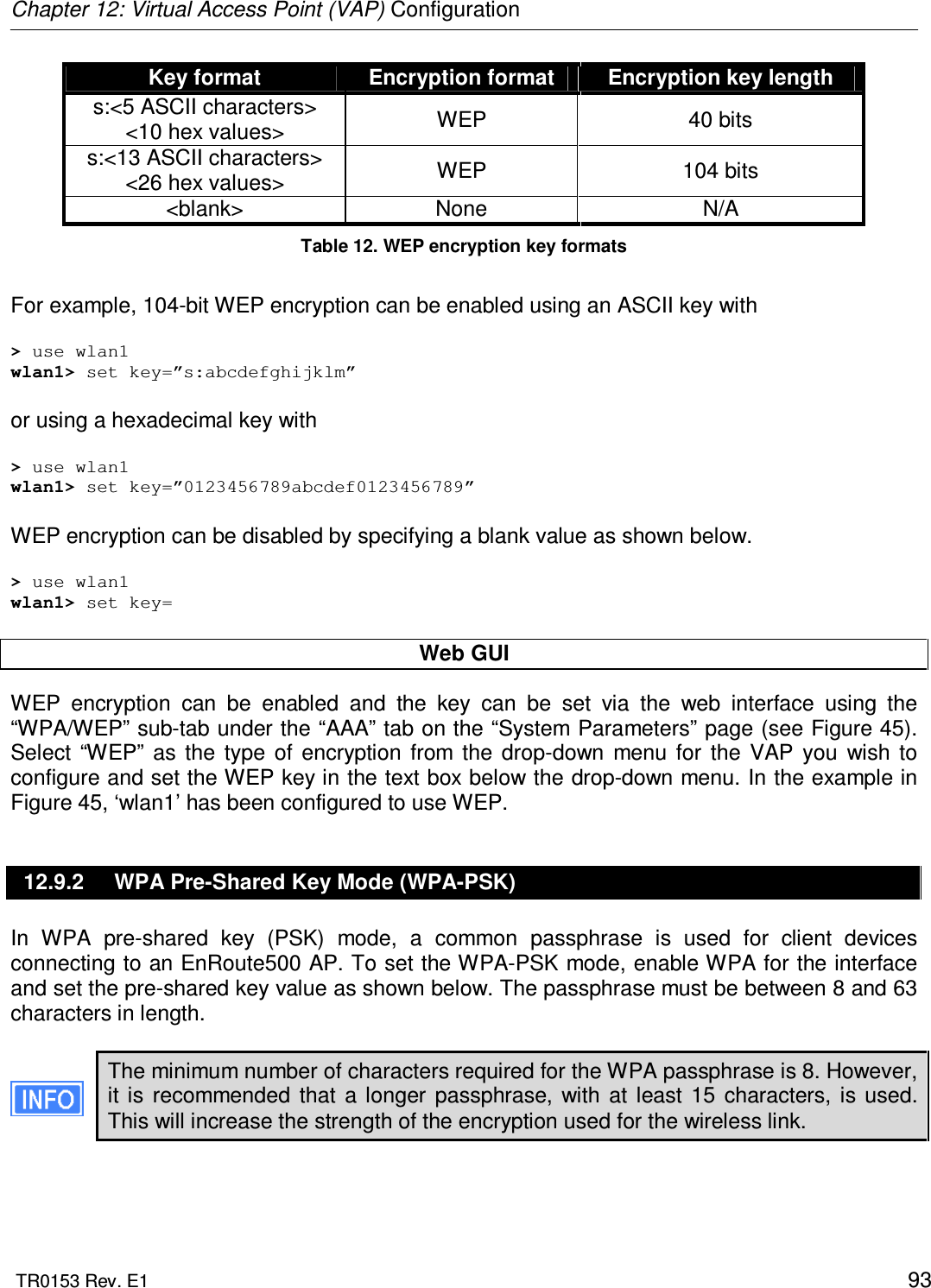
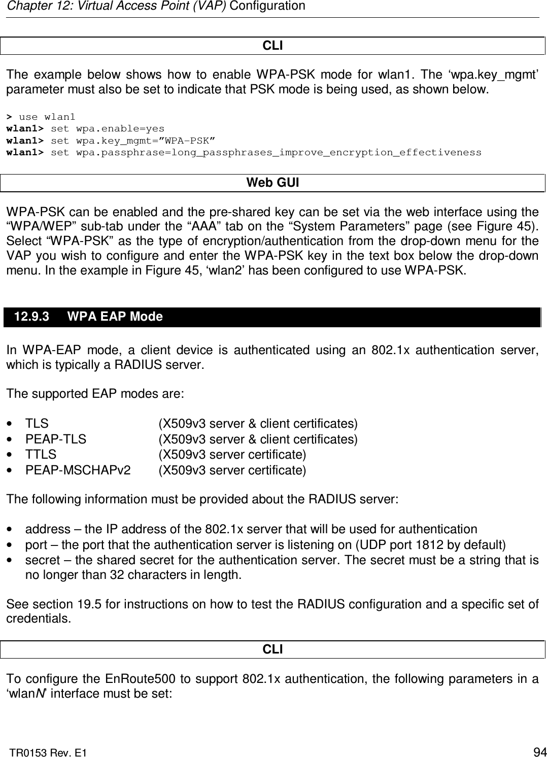
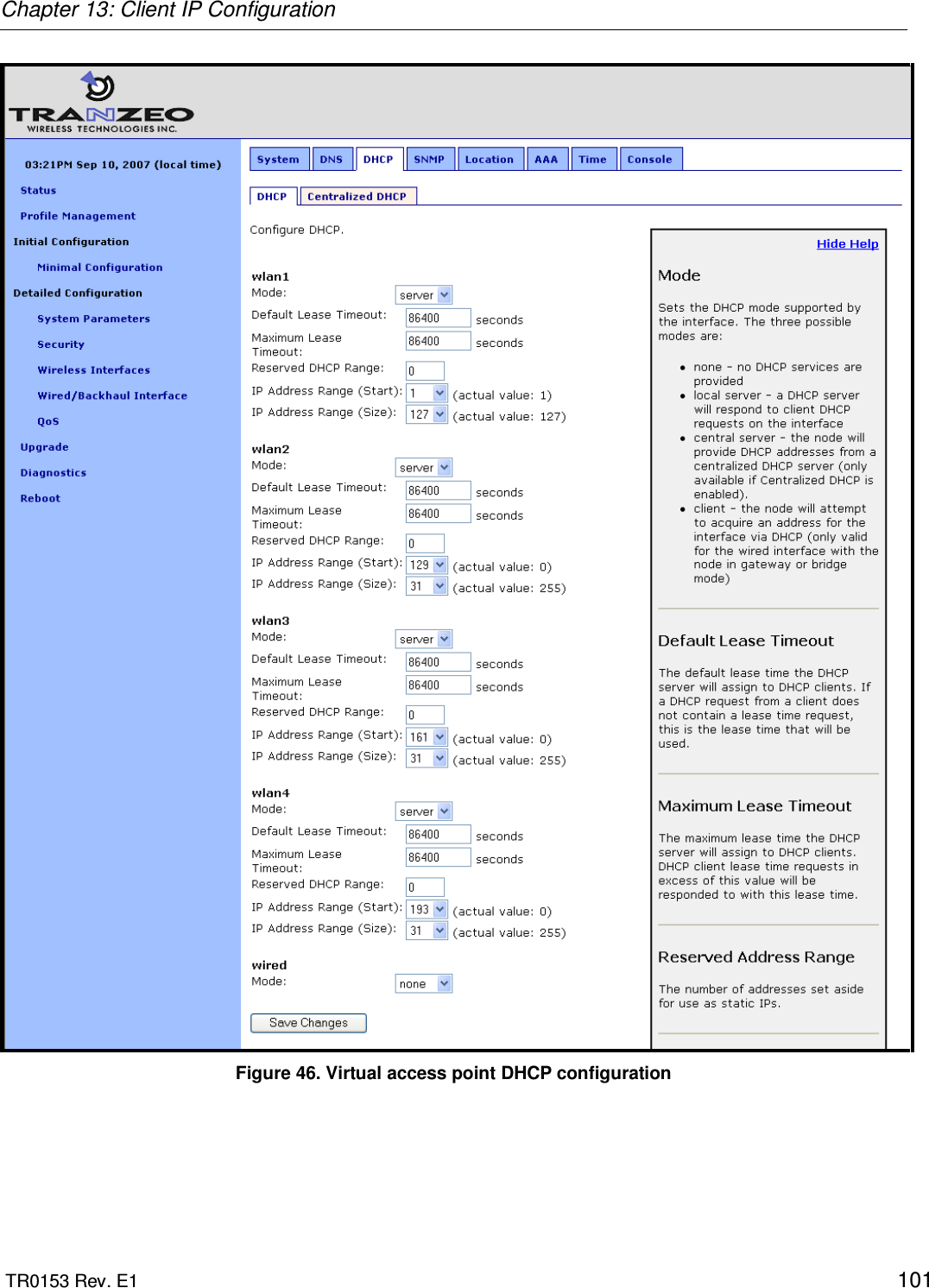
![Chapter 12: Virtual Access Point (VAP) Configuration TR0153 Rev. E1 85 Mode value Mode 2 802.11b 3 802.11b/g Table 10. VAP mode value/mode mapping Web GUI The VAP’s client type mode can be set via the web interface using the appropriate “wlanN” tab on the “Wireless Interfaces” page (see Figure 42). Two client type options are available: “802.11b only” and “802.11b/g”. 12.4 Access Point Client Device Address Space Each VAP interface is either assigned a segment of the EnRoute500’s class C client address space, if the device is using the implicit addressing scheme, or an arbitrary address space can be set for the interface when using the explicit addressing scheme. See section 9 for more information on client addressing schemes. The EnRoute500 VAPs’ interface IP configurations can be changed directly when it is using the explicit addressing scheme. They cannot be changed directly when the device is using the implicit addressing scheme. When an EnRoute500 is configured to use the implicit addressing scheme, set the IP address to the desired value by modifying the node ID, mesh ID, and LAN prefix parameters (see sections 8.3 and 9.1.1). Set the netmask by changing the client address space segments as described in 9.1.2. When using the explicit addressing scheme, the IP configuration can be set directly. Care must be taken to avoid using the same or overlapping address spaces on different devices in a common mesh. CLI You can view the IP settings for the VAP interfaces with the ‘ip.*’ parameters in the appropriate ‘wlanN’ interface as shown in the example below. > use wlan1 wlan1> get ip.* ip.address = 10.2.4.1 [read-only] ip.address_force = ip.broadcast = 10.2.4.127 [read-only] ip.broadcast_force = ip.gateway = [read-only] ip.gateway_force = ip.netmask = 255.255.255.0 [read-only]](https://usermanual.wiki/Tranzeo-Wireless-Technologies/GNADX2NT4/User-Guide-1467570-Page-85.png)
![Chapter 12: Virtual Access Point (VAP) Configuration TR0153 Rev. E1 86 ip.netmask_force = ip.implicit.size.actual = [read-only] ip.implicit.size.requested = 31 ip.implicit.start.actual = [read-only] ip.implicit.start.requested = 1 When an EnRoute500 is using the implicit addressing scheme, the VAP IP settings can be changed by altering the ‘id.node’, ‘id.mesh’, and ‘id.lanprefix’ parameters in the ‘sys’ interface and the ‘ip.implicit.start.requested’ parameter in the appropriate ‘wlanN’ interface. When an EnRoute500 is using the explicit addressing scheme, the IP address, netmask, gateway address, and broadcast address can be set using the ‘ip.address_force’, ‘ip.netmask_force’, ‘ip.gateway_force’, and ‘ip.broadcast_force’ parameters in the appropriate ‘wlanN’ interface as shown in the example below. > use wlan1 wlan1> set ip.address_force=10.12.8.1 wlan1> set ip.broadcast_force=10.12.8.255 wlan1> set ip.gateway_force= wlan1> set ip.netmask_force=255.255.255.0 Web GUI The current VAP IP settings can be viewed through the web interface on the “Config Overview” tab on the “Status” page. When using the implicit addressing scheme, the VAP IP settings can be changed by altering the node ID, mesh ID, and LAN prefix settings on the “System” parameters tab on the “System Parameters” page. When using the explicit addressing scheme, the IP parameters can be set on the appropriate tab on the “Wireless Interface” page.](https://usermanual.wiki/Tranzeo-Wireless-Technologies/GNADX2NT4/User-Guide-1467570-Page-86.png)