Tranzeo Wireless Technologies GNADX2NT4 WIRELESS MESH ROUTER User Manual USERS MANUAL
Tranzeo Wireless Technologies, Inc WIRELESS MESH ROUTER USERS MANUAL
USERS MANUAL

Document No. TR0153 Rev E2
EnRoute50x/51x
User’s Guide
Rev. E1
Communicate Without Boundaries
Tranzeo Wireless Technologies Inc.
19473 Fraser Way, Pitt Meadows, BC, Canada V3Y 2V4
www.tranzeo.com
technical support email: support@tranzeo.com

EnRoute50x/51x User’s Guide
TR0153 Rev. E1 2
Tranzeo, the Tranzeo logo and EnRoute500 are trademarks of Tranzeo Wireless Technologies Inc.. All rights
reserved.
All other company, brand, and product names are referenced for identification purposes only and may be
trademarks that are the properties of their respective owners.
Copyright © 2007, Tranzeo Wireless Technologies Inc..
EnRoute50x/51x User’s Guide
TR0153 Rev. E1 3
FCC Notice to Users and Operators
This device complies with Part 15 of the FCC Rules. Operation is subject to the following two
conditions: (1) This device may not cause harmful interference, and (2) This device must
accept any interference received, including interference that may cause undesired operation.
This equipment has been tested and found to comply with the limits for Class B Digital Device,
pursuant to Part 15 of the FCC Rules. These limits are designed to provide reasonable
protection against harmful interference in a residential installation. This equipment generates
and can radiate radio frequency energy and, if not installed and used in accordance with the
instructions, may cause harmful interference to radio communications. However, there is no
guarantee that interference will not occur in a particular installation. If this equipment does
cause harmful interference to radio or television reception, which can be determined by turning
the equipment off and on, the user is encouraged to try to correct the interference by one or
more of the following measures.
• Reorient or relocate the receiving antenna
• Increase the separation between the equipment and receiver
• Connect the equipment into an outlet on a circuit different from that to which the receiver is
connected
• Consult the dealer or an experienced radio/TV technician for help
To reduce potential radio interference to other users, the antenna type and its gain should be
so chosen that the equivalent isotropically radiated power (EIRP) is not more than that
required for successful communication.
• This device must be installed so that there is a minimum of 172.9 cm between the
antenna and any person.
Any changes or modification to said product not expressly approved by Tranzeo
Wireless Technologies Inc. could void the user's authority to operate this device.
The Tranzeo EnRoute500 Mesh Router must be installed by a trained professional,
value added reseller, or systems integrator who is familiar with RF cell planning
issues and the regulatory limits defined by the FCC for RF exposure, specifically
those limits outlined in sections 1.1307.

EnRoute50x/51x User’s Guide
TR0153 Rev. E1 4
Table of Contents
1 Working with the EnRoute500........................................................................... 9
1.1 EnRoute500 Variants ............................................................................................9
1.2 EnRoute500 Capabilities.....................................................................................10
1.3 Network Topology ...............................................................................................10
1.4 Network Terminology ..........................................................................................11
1.5 EnRoute500 Interfaces........................................................................................12
1.5.1 Ethernet and PoE............................................................................................... 13
1.5.2 Antennas............................................................................................................ 14
1.6 Deployment Considerations ................................................................................14
1.6.1 Mesh Channel Selection .................................................................................... 14
1.6.2 AP Channel Selection ........................................................................................ 15
2 Connecting to the EnRoute500 ....................................................................... 16
2.1 Network Interfaces ..............................................................................................16
2.2 Connecting to an Unconfigured EnRoute500......................................................17
2.3 Default Login and Password ...............................................................................18
2.4 Resetting the ‘admin’ Password ..........................................................................18
3 Using the Web Interface .................................................................................. 19
3.1 Accessing the Web Interface...............................................................................19
3.2 Navigating the Web Interface..............................................................................21
3.3 Setting Parameters .............................................................................................21
3.4 Help Information..................................................................................................22
3.5 Rebooting............................................................................................................22
4 Using the Command Line Interface ................................................................ 24
4.1 Accessing the CLI ...............................................................................................24
4.2 User Account.......................................................................................................24
4.3 CLI Interfaces......................................................................................................25
4.4 CLI Features .......................................................................................................25
4.4.1 Control of the Cursor.......................................................................................... 25
4.4.2 Cancel a Command ........................................................................................... 25
4.4.3 Searching the Command History ....................................................................... 26
4.4.4 Executing a Previous Command ........................................................................ 26
4.5 CLI Commands ...................................................................................................26
4.5.1 ‘?’ command....................................................................................................... 26
4.5.2 ‘whoami’ command ............................................................................................ 26
4.5.3 ‘help’ command .................................................................................................. 27
4.5.4 ‘show’ command ................................................................................................ 27
4.5.5 ‘use’ command ................................................................................................... 28
4.5.6 ‘set’ command .................................................................................................... 29

EnRoute50x/51x User’s Guide
TR0153 Rev. E1 5
4.5.7 ‘get’ command.................................................................................................... 30
4.5.8 ‘list’ command .................................................................................................... 31
4.5.9 ‘ping’ command .................................................................................................. 31
4.5.10 ‘ifconfig’ command ............................................................................................. 32
4.5.11 ‘route’ command................................................................................................. 32
4.5.12 ‘clear’ command ................................................................................................. 32
4.5.13 ‘history’ command .............................................................................................. 33
4.5.14 ‘!’ command........................................................................................................ 34
4.5.15 ‘exit’ command ................................................................................................... 35
4.5.16 ‘quit’ command ................................................................................................... 35
5 Initial Configuration of an EnRoute500 .......................................................... 36
6 Status Information ........................................................................................... 39
6.1 Configuration Overview Page..............................................................................39
6.2 Interface Status ...................................................................................................40
6.2.1 Mesh and Virtual AP Interfaces.......................................................................... 40
6.2.2 Wired Interface Status........................................................................................ 41
6.3 Routing Table......................................................................................................42
6.4 ARP Table...........................................................................................................43
6.5 Event Log............................................................................................................43
6.6 DHCP Event Log.................................................................................................44
7 Configuration Profile Management................................................................. 46
7.1 Saving the Current Configuration ........................................................................46
7.2 Load a Configuration Profile................................................................................47
7.3 Delete a Configuration Profile .............................................................................48
7.4 Downloading a Configuration Profile from an EnRoute500 .................................48
7.5 Uploading a Configuration Profile to an EnRoute500..........................................49
8 System Settings ............................................................................................... 50
8.1 User Password....................................................................................................50
8.2 Operating Scheme ..............................................................................................51
8.3 Using Multiple Gateways.....................................................................................52
8.4 Mesh / Node ID ...................................................................................................53
8.5 Mesh Prefix .........................................................................................................53
8.6 Internal and External Subnets.............................................................................54
8.7 DNS / Domain Settings .......................................................................................55
8.8 DNS Proxy Configuration ....................................................................................56
8.9 NetBIOS Server ..................................................................................................57
8.10 SNMP..................................................................................................................58
8.11 Location...............................................................................................................59
8.12 Cluster Name ......................................................................................................60
8.13 Certificate Information .........................................................................................61
8.14 Time Synchronization..........................................................................................61
8.15 Web GUI Console ...............................................................................................63
8.16 OnRamp Configuration Access...........................................................................64

EnRoute50x/51x User’s Guide
TR0153 Rev. E1 6
8.17 CLI Timeout.........................................................................................................65
9 Client Addressing Schemes............................................................................ 66
9.1 Implicit Addressing Scheme ................................................................................67
9.1.1 LAN Prefix.......................................................................................................... 68
9.1.2 Client Address Space Segmentation in Implicit Addressing Mode ..................... 68
9.2 Explicit Addressing Scheme................................................................................71
10 Mesh Radio Configuration............................................................................... 72
10.1 Channel...............................................................................................................72
10.2 Service Set Identifier (SSID) ...............................................................................73
10.3 Encryption ...........................................................................................................74
10.4 Transmit Power Cap ...........................................................................................74
10.5 RSSI Threshold Levels........................................................................................75
10.6 IP Configuration ..................................................................................................76
10.7 Neighbor Status ..................................................................................................76
11 Ethernet Interface Configuration .................................................................... 77
11.1 IP Configuration for Repeater Devices and Their Clients....................................77
11.1.1 Ethernet Client Device Address Space .............................................................. 77
11.1.2 Ethernet Interface IP Configuration .................................................................... 78
11.1.3 IP Configuration of Client Devices via DHCP..................................................... 79
11.1.4 Manual IP Configuration of Client Devices......................................................... 79
11.2 IP Configuration for Gateway Devices ................................................................80
11.2.1 DHCP................................................................................................................. 80
11.2.2 Manual IP Configuration..................................................................................... 81
12 Virtual Access Point (VAP) Configuration ..................................................... 83
12.1 Access Point Interfaces.......................................................................................84
12.2 Enabling and Disabling Access Points ................................................................84
12.3 Virtual Access Point Client Types .......................................................................84
12.4 Access Point Client Device Address Space ........................................................85
12.5 Channel...............................................................................................................87
12.6 ESSID .................................................................................................................88
12.7 IP Configuration of Client Devices.......................................................................89
12.7.1 IP Configuration of Clients Devices via DHCP ................................................... 90
12.7.2 Manual IP Configuration of Client Devices......................................................... 90
12.8 Client Devices .....................................................................................................90
12.9 Encryption and Authentication.............................................................................91
12.9.1 WEP Encryption ................................................................................................. 92
12.9.2 WPA Pre-Shared Key Mode (WPA-PSK)........................................................... 93
12.9.3 WPA EAP Mode................................................................................................. 94
12.10 Transmit Power Cap ...........................................................................................95
12.11 Radio Rate ..........................................................................................................96
12.12 Preamble Length.................................................................................................96
12.13 Beacon Interval ...................................................................................................97
12.14 Maximum Link Distance ......................................................................................97

EnRoute50x/51x User’s Guide
TR0153 Rev. E1 7
13 Client IP Configuration via DHCP ................................................................... 99
13.1 Using the Local DHCP Server.............................................................................99
13.2 Using a Centralized DHCP Server ....................................................................102
13.2.1 Support for Clients with Static IP Addresses.................................................... 103
13.2.2 Configuring the EnRoute500s .......................................................................... 103
13.2.3 Configuring the Central DHCP Server.............................................................. 106
14 Connecting an EnRoute500 Mesh Network to a WAN................................. 107
14.1 Static Routing Configuration on WAN Router....................................................107
14.1.1 “Single Gateway, Implicit Addressing Scheme” Option .................................... 107
14.1.2 “Single Gateway, Explicit Addressing Scheme” Option.................................... 108
14.1.3 “Multiple Gateway, Implicit Addressing Scheme” Option.................................. 108
14.1.4 “Multiple Gateway, Explicit Addressing Scheme” Option ................................. 109
14.2 Network Address Translation (NAT) on Mesh Gateways ..................................109
14.3 Layer 2 Mesh Emulation in DHCP Relay Mode.................................................110
14.4 VPN Access to a Mesh Gateway ......................................................................111
15 Controlling Access to the EnRoute500 ........................................................ 112
15.1 Firewall..............................................................................................................112
15.2 Gateway Firewall...............................................................................................113
15.3 Blocking Client-to-Client Traffic.........................................................................114
15.4 Connection Tracking .........................................................................................116
15.4.1 Limiting Number of TCP Connections Per Client Device.................................. 116
15.4.2 Connection Tracking Table Size ...................................................................... 116
15.4.3 Connection Tracking Timeout .......................................................................... 117
15.5 Custom Firewall Rules ......................................................................................117
15.6 Access Control Lists (ACLs)..............................................................................119
15.6.1 Access Point Access Control Lists (ACLs)....................................................... 119
15.6.2 Mesh ACL ........................................................................................................ 120
16 Quality of Service (QoS) Configuration........................................................ 122
16.1 Priority Levels....................................................................................................122
16.2 Rate Limiting .....................................................................................................125
16.3 Rate Reservation ..............................................................................................127
17 Enabling VLAN Tagging ................................................................................ 130
17.1 Client Access Interface Configuration ...............................................................130
17.2 Gateway Configuration......................................................................................131
18 Integration with Enterprise Equipment ........................................................ 133
18.1 Configuring Splash Pages.................................................................................133
18.1.1 Enabling Splash Pages .................................................................................... 133
18.1.2 Configuring Splash URLs................................................................................. 135
18.1.3 Sample HTML Code for Splash Pages............................................................. 136
18.1.4 Configuring the Authentication Server.............................................................. 137
18.1.5 Trusted MAC Addresses .................................................................................. 138
18.1.6 Bypass Splash Pages for Access to Specific Hosts ......................................... 139

EnRoute50x/51x User’s Guide
TR0153 Rev. E1 8
18.2 Layer 2 Emulation .............................................................................................140
19 Diagnostics Tools .......................................................................................... 143
19.1 Ping...................................................................................................................143
19.2 Traceroute.........................................................................................................144
19.3 Packet Capture .................................................................................................144
19.4 Centralized DHCP Testing ................................................................................147
19.5 RADIUS Server Testing ....................................................................................147
19.6 Diagnostic Dump...............................................................................................148
20 Firmware Management .................................................................................. 150
20.1 Displaying the Firmware Version.......................................................................150
20.2 Upgrading the Firmware....................................................................................150
20.2.1 Upgrading the Firmware on all Devices in a Mesh Neighborhood.................... 151
20.2.2 Upgrading the Firmware on an Individual Device............................................. 153
Glossary …........................................................................................................................... 155
Abbreviations....................................................................................................................... 156

Chapter 1: Working with the EnRoute500
TR0153 Rev. E1 9
1 Working with the EnRoute500
Thank you for choosing the Tranzeo EnRoute500 Wireless Mesh Router. The EnRoute500
allows a wireless mesh network to be rapidly deployed with minimal configuration required by
the end user. This user’s guide presents a wide array of configuration options, but only a
limited number of options have to be configured in order to deploy a mesh network of
EnRoute500s.
1.1 EnRoute500 Variants
The following is a list of Enroute varients, as shown in Table 1.
Model Number Included Antennas
EnRoute500 AP 5dBi, Mesh 8.5dBi
EnRoute510 AP 7.5dBi, Mesh
10.5dBi
Table 1. EnRoute500 variants
The following is a list of supported accessory antennas sold with the Enroute family, as shown
in Table 2.
Model Number Included Antennas
TR-ODH24-12 Vertical Omnidrectional 2.4 Ghz 12 dBi
TR-SA24-90-9 Vertical Sector, 2.4 Ghz, 90 degree, 9 dBi
TR-HTQ-5.8-12 Vertical Omnidrectional, 5.8 Ghz, 12 dBi
TR-58V-60-17 Vertical Sector, 5.8 Ghz, 60 degree, 17 dBi
TR-5X-Ant-24 Panel, 5.8 Ghz, 24 dBi
TR-5.8-32Db-Ant Parabolic dish, 5.8 Ghz, 32 dBi
Table 2 Supported Accessory antennas
Throughout the manual, “EnRoute500” will be used to collectively refer to this family
of products. Where the functionality of the variants differ, the actual model number
will be used.
Chapter 1: Working with the EnRoute500
TR0153 Rev. E1 10
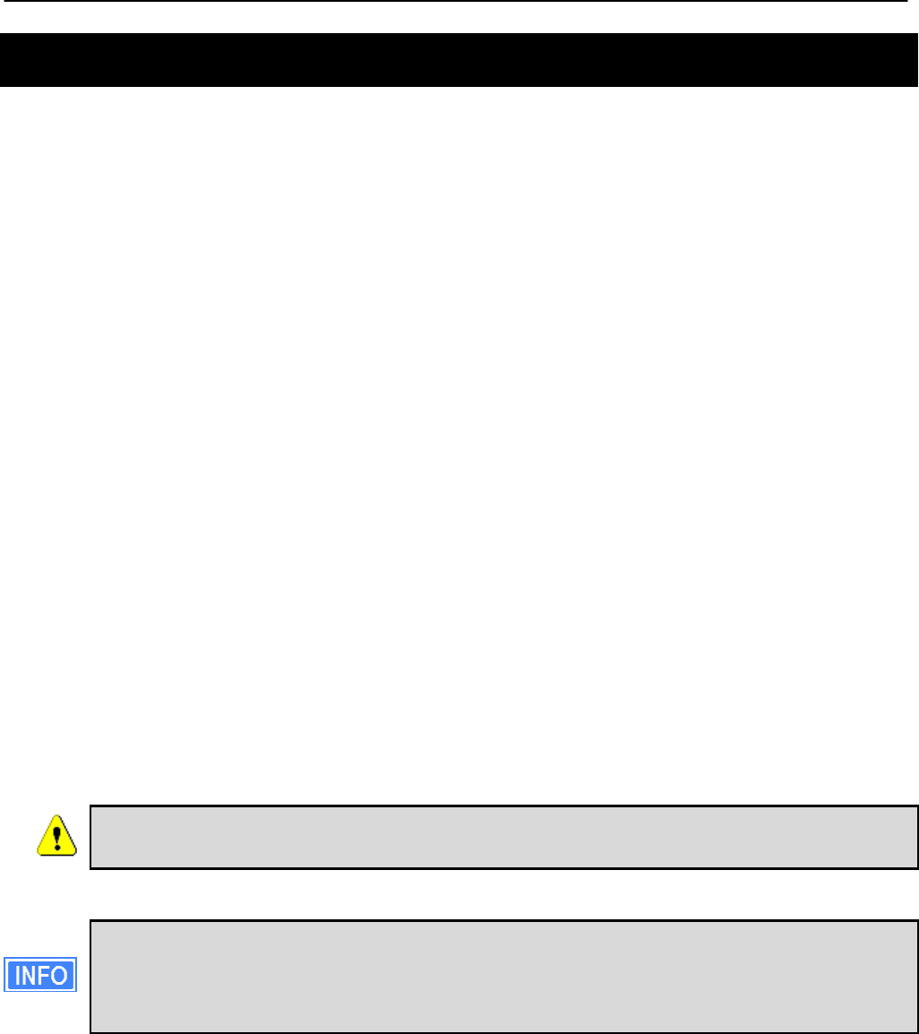
1.2 EnRoute500 Capabilities
The EnRoute500 is capable of automatically forming a mesh network that allows devices that
are connected to it, either with a wired or a wireless connection, to communicate with each
other and external networks that are accessed through gateway devices. The EnRoute500 has
two radios, an 802.11a mesh backhaul radio and an access point radio for 802.11b/g-client
devices. An EnRoute500 will currently support up to four virtual access points (VAPs), each
with different access and performance settings. It is also possible to connect devices to an
EnRoute500 using an Ethernet connection.
Figure 1. EnRoute500 sample network – devices attach to
the EnRoute500 through both wired and wireless connections
1.3 Network Topology
EnRoute500s can be used to create two network topologies: a stand-alone network or an
Internet extension network that attaches to a network with connectivity to the Internet.
Chapter 1: Working with the EnRoute500
TR0153 Rev. E1 11
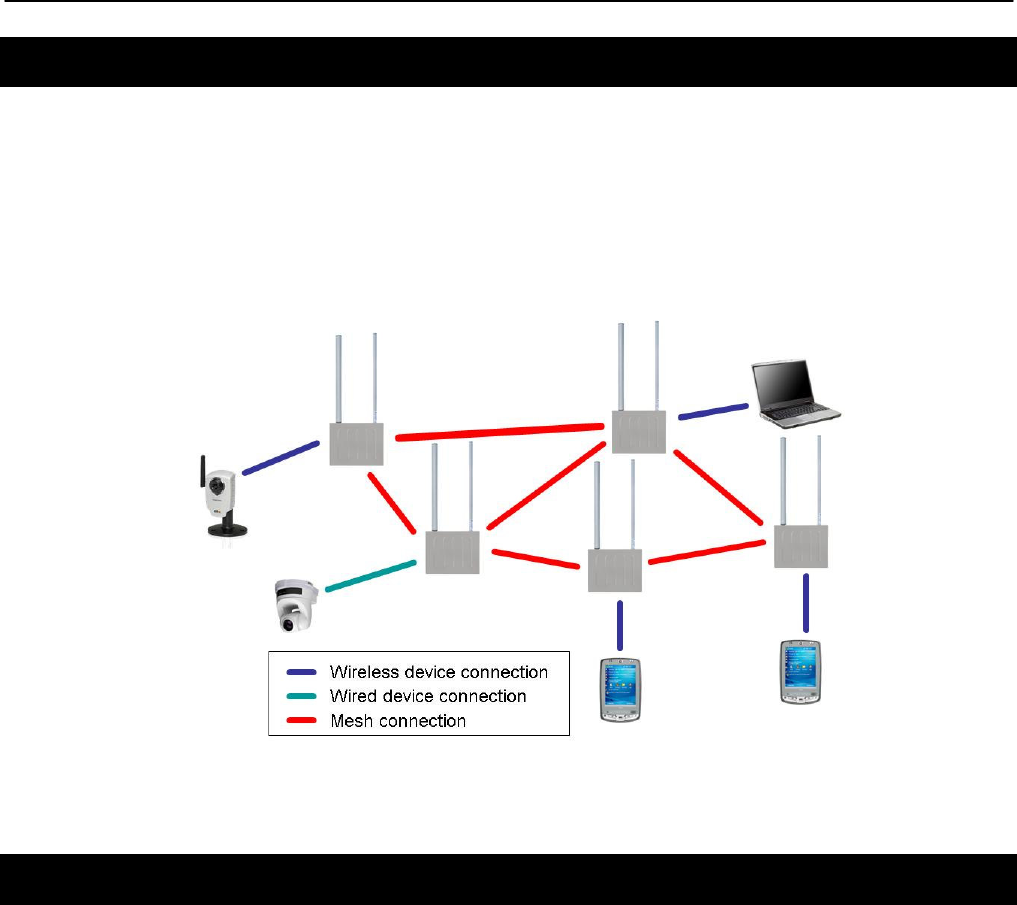
Figure 2. Internet extension network
An Internet extension network (shown in Figure 2) is typically used when the goal is to provide
Internet access to a number of clients that connect to the mesh network. Alternatively, this
configuration can be used to provide access for client devices to remote resources on a private
network. The key feature to note is that there is a gateway device that provides access from
the mesh network to an external network.
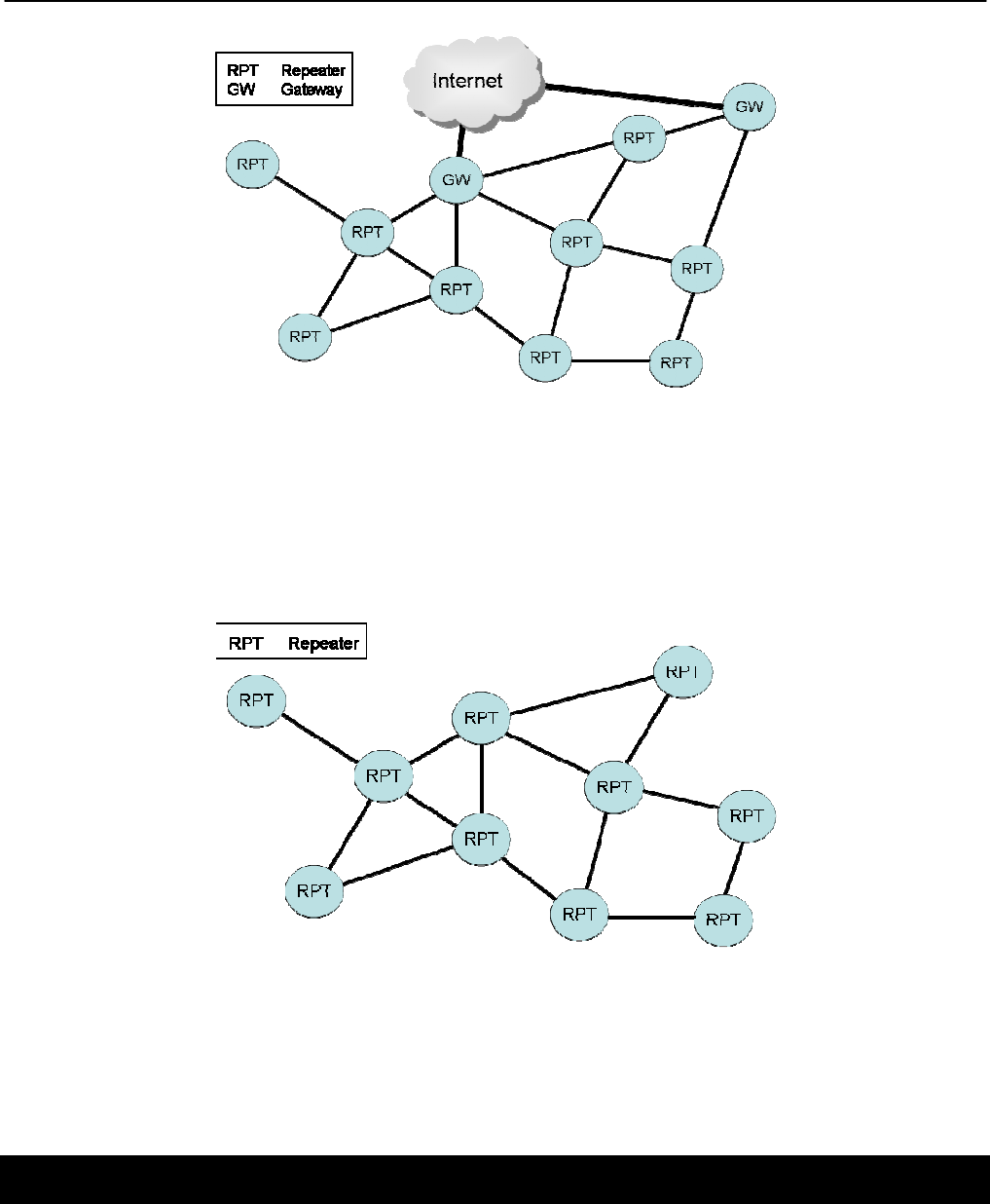
Figure 3. Stand-alone network
In a stand-alone network, as shown in Figure 3, all devices are configured to operate in the
same mode (repeater mode). This network configuration is suitable for applications where the
clients using the mesh only need to communicate with each other and do not need to access
the Internet or other remote network resources that are not directly connected to the mesh.
1.4 Network Terminology
The following terms will be referred to throughout this manual.
Chapter 1: Working with the EnRoute500
TR0153 Rev. E1 12
Mesh neighborhood – a group of two or more EnRoute500 devices with at least one
configured as a gateway
Mesh device – a single EnRoute500 that is part of a mesh network
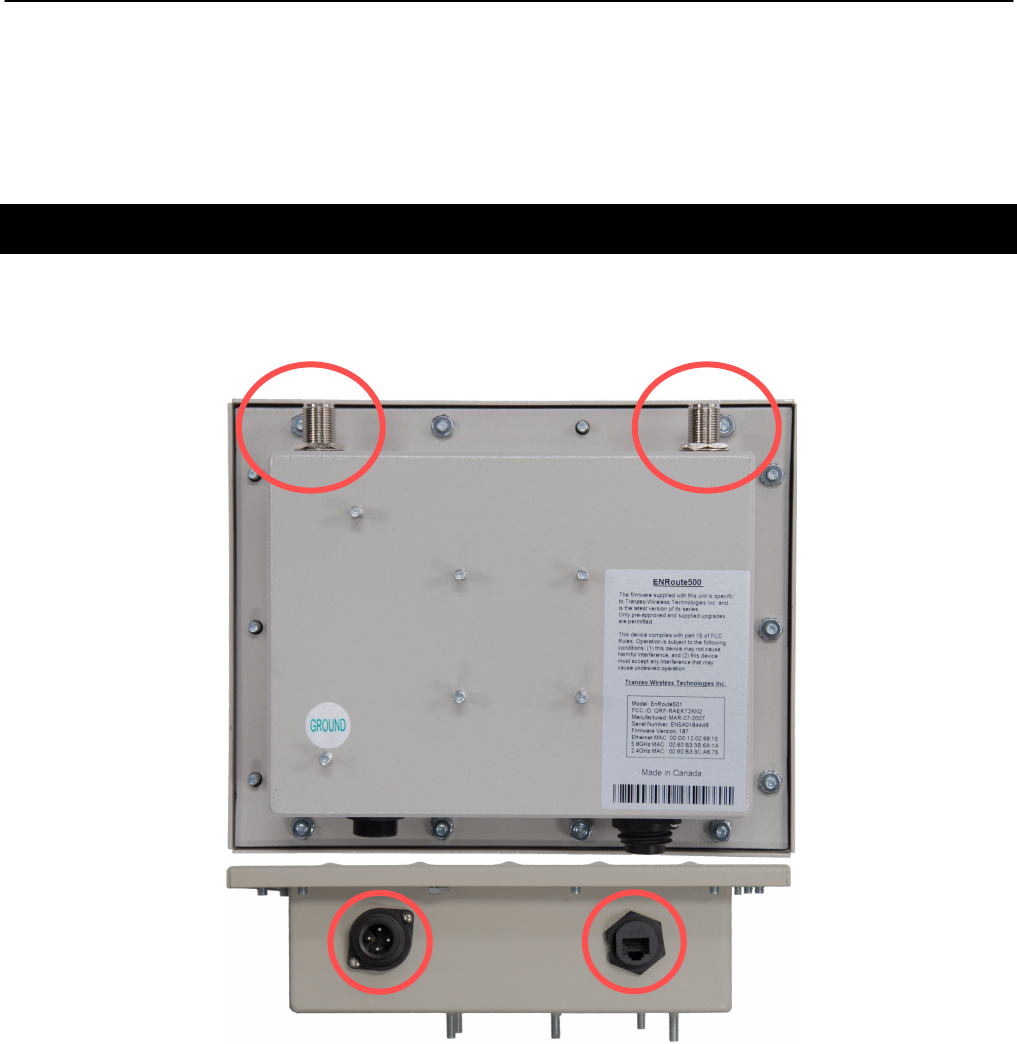
1.5 EnRoute500 Interfaces
The interfaces available on the EnRoute500 are Ethernet and two radio ports. On the
EnRoute5x1 models, an external AC power port is also present.
Power Ethernet
Figure 4. EnRoute500 interfaces. EnRoute501 shown
AP
radio
port
Mesh
r
adio
port

Chapter 1: Working with the EnRoute500
TR0153 Rev. E1 13
Interface Description
Power (EnRoute 5x1 only) Power input (100-240VAC 50-60 Hz)
Mesh radio port N-type antenna connector for mesh radio
AP radio port N-type antenna connector for access point radio
Ethernet 10/100 Mbit Ethernet interface
Passive PoE PoE power input (9-28VDC, 12W)
Not compatible with IEEE 802.3af
Table 2. EnRoute500 Interfaces
1.5.1 Ethernet and PoE
The EnRoute500 has a 10/100 Ethernet port that supports passive Power over Ethernet (PoE).
The PoE power injector should supply an input voltage between 9-28VDC and a minimum of
12W. The pinout for the Ethernet interface on the EnRoute500 is provided in Table 3.
The EnRoute500 is equipped with an auto-sensing Ethernet port that allows both
regular and cross-over cables to be used to connect to it.
Pin Signal Standard Wire Color
1 Tx+ White/Orange
2 Tx- Orange
3 Rx+ White/Green
4 PoE V+ Blue
5 PoE V+ White/Blue
6 Rx- Green
7 Gnd White/Brown
8 Gnd Brown
Table 3. Ethernet port pinout
To power the EnRoute500, connect an Ethernet cable from the Ethernet port of the
EnRoute500 to the port labeled “CPE” on the supplied PoE injector and apply power to the
PoE injector using the supplied power supply

Chapter 1: Working with the EnRoute500
TR0153 Rev. E1 14
DO NOT CONNECT ANY DEVICE OTHER THAN THE ENROUTE500 TO THE
PORT LABELED “CPE” ON THE PoE INJECTOR. NETWORK EQUIPMENT
THAT DOES NOT SUPPORT PoE CAN BE PERMANENTLY DAMAGED BY
CONNECTING TO A PoE SOURCE. NOTE THAT MOST ETHERNET
INTERFACES ON PERSONAL COMPUTERS (PCs), LAPTOP/NOTEBOOK
COMPUTERS, AND OTHER NETWORK EQUIPMENT (E.G. ETHERNET
SWITCHES AND ROUTERS) DO NOT SUPPORT PoE.
1.5.2 Antennas
Attach the supplied antennas to the mesh and access point (AP) radio ports on the
EnRoute500. The antennas used for the two radios are band-specific and therefore it is
important to correctly match the antennas with the radio ports.
The thicker of the two antennas is the 2.4 GHz antenna, which should be attached to the AP
connector. The thinner antenna is the 5.8 GHz antenna, which should be attached to the mesh
connector.
1.6 Deployment Considerations
The EnRoute500’s radios operate in the unlicensed 2.4 GHz and 5.8 GHz ISM bands. It is
possible that there will be other devices operating in these bands that will interfere with the
EnRoute500’s radios. Interference from adjacent EnRoute500s can also degrade performance
if the EnRoute500s are not configured properly.
It is advisable to carry out a site survey prior to installation to determine what devices are
operating in the two bands that the EnRoute500 uses. To detect the presence of other 802.11
devices, a tool such as Netstumbler (http://www.netstumbler.com/downloads/) can be used. A
spectrum analyzer can be used for further characterization of interference in the band.
1.6.1 Mesh Channel Selection
The mesh radio channel must be the same for all EnRoute500s in a given mesh neighborhood.
Adjacent mesh neighborhoods will get a performance benefit if they are on different channels
as the neighborhoods will not interfere with each other. The 802.11a channels that the
EnRoute500 mesh radio can be configured to use are all non-overlapping.

Chapter 1: Working with the EnRoute500
TR0153 Rev. E1 15
1.6.2 AP Channel Selection
The access point radio channels used by the EnRoute500s in a mesh neighborhood may
differ. It is advisable to use different access point channels for adjacent mesh devices to
reduce interference.
However, it may be more important to select the access point channel based on the presence
of other 802.11 devices in the area rather than configuring it to be different than that of an
adjacent EnRoute500. A site survey should be conducted to determine which access point
channel will provide the best performance.
Some of the 802.11b/g channels that the EnRoute500 access point radio can be configured to
use are overlapping. Only channels 1, 6, and 11 are non-overlapping.

Chapter 2: Connecting to the EnRoute500
TR0153 Rev. E1 16
2 Connecting to the EnRoute500
The EnRoute500 can be configured and monitored by connecting to one of its network
interfaces. The wired Ethernet interface on the EnRoute500 should be used for initial
configuration of the device, but other network interfaces can be used to connect to the device
after initial configuration has been completed.
2.1 Network Interfaces
The EnRoute500 has several network interfaces, as shown in Table 4.
The network interfaces listed in the table below are logical, not hardware, interfaces.
Some of the interfaces listed in the table share the same hardware interface.
Interface
Hardware
Interface Primary Function
Interface
Availability
Default
Address
Fixed
Address?
Wired Ethernet
Connecting to a WAN or
supporting wired client
connections
Enabled by
default 10.253.253.225/27 No
Static
Configuration Ethernet
Configuring the device
before a unique Ethernet
IP address has been
configured
Always
present 169.254.253.253/16 Yes
OnRamp
Configuration Ethernet
Configuring the device
before a unique Ethernet
IP address has been
configured. Unlike the
static configuration
interface, this interface’s
address can be modified,
allowing multiple
unconfigured
EnRoute500s to be
attached to a LAN
Disabled by
default N/A No
Mesh Mesh
radio Mesh communication Always
present 172.29.253.253/16 No
VAP 1 – 4 AP radio Connecting to wireless
clients
Only VAP1
enabled by
default
10.253.253.1/26
10.253.253.129/27
10.253.253.161/27
10.253.253.193/27
No
Centralized
DHCP
Provides a gateway for
client devices when using
centralized DHCP server
mode
All disabled
by default N/A No
Table 4. EnRoute500 network interfaces
Chapter 2: Connecting to the EnRoute500
TR0153 Rev. E1 17
Note that the “Static Configuration” interface is the only interface that has a fixed address that
cannot be changed by the user. Since this interface is known to always be present, it can be
used for initial configuration and for accessing devices whose configuration settings are
unknown.
2.2 Connecting to an Unconfigured EnRoute500
Use the Static Configuration interface with IP address 169.254.253.253 and netmask
255.255.0.0 to establish network connectivity to an unconfigured EnRoute500.
The Static Configuration interface functions only with the EnRoute500’s wired
interface. Do not try to access the EnRoute500 over a wireless link using the
address of this interface.
To connect to an EnRoute500 using its Static Configuration IP address, you must configure
your computer’s IP address to be in the 169.254.253.253/16 subnet, e.g. 169.254.253.1 and
connect the computer’s Ethernet cable to the “DATA” port on the EnRoute500’s PoE injector.
ENSURE THAT THE DATA CONNECTION FROM THE PC OR THE LAN IS MADE
TO THE “PC” PORT. DO NOT CONNECT ANY DEVICE OTHER THAN THE
ENROUTE500 TO THE PORT LABELED “CPE” ON THE PoE INJECTOR.
NETWORK EQUIPMENT THAT DOES NOT SUPPORT PoE CAN BE
PERMANENTLY DAMAGED BY CONNECTING TO A PoE SOURCE. NOTE THAT
MOST ETHERNET INTERFACES ON PERSONAL COMPUTERS (PCs),
LAPTOP/NOTEBOOK COMPUTERS, AND OTHER NETWORK EQUIPMENT
(E.G. ETHERNET SWITCHES AND ROUTERS) DO NOT SUPPORT PoE.
Since the Static Configuration IP address is the same for all EnRoute500s, you
should not simultaneously connect multiple EnRoute500s to a common LAN
and attempt to access them using the Static Configuration IP address.

Chapter 2: Connecting to the EnRoute500
TR0153 Rev. E1 18
If you are configuring multiple EnRoute500s with the same computer in rapid
succession, it may be necessary to clear the ARP cache since the IP addresses for
the EnRoute500s will all be the same, but the MAC addresses will vary. The
following commands can be used to clear the ARP cache
Windows XP (executed in a command prompt window)
arp -d *
to clear the entire cache, or
arp -d 169.254.253.253
to just clear the EnRoute500 entry
Linux
arp -d 169.254.253.253
2.3 Default Login and Password
The EnRoute500’s default login is ‘admin’ and the default password is ‘default’. The login and
password are the same for the web interface and the CLI. Changing the password using one of
the interfaces will change it for the other interface as well.
2.4 Resetting the ‘admin’ Password
The EnRoute500 supports a password recovery feature for the ‘admin’ account, should the
password be lost.
Completing the password recovery procedure requires that you contact
Tranzeo technical support. Please check the Tranzeo website
(www.tranzeo.com) for how to contact technical support and hours of
operation.
For security purposes, the ‘admin’ password can only be reset in the first 15
minutes of operation of the device. You will be able to power the unit on and
off to be able to reset the password.
Chapter 3: Using the Web Interface
TR0153 Rev. E1 19
3 Using the Web Interface
The EnRoute500 has a web interface accessible through a browser that can be used to
configure the device and display status parameters.
3.1 Accessing the Web Interface
You can access the web interface by entering one of the EnRoute500’s IP addresses in the
URL field of a web browser (see section 2.2 for a description of how to access an unconfigured
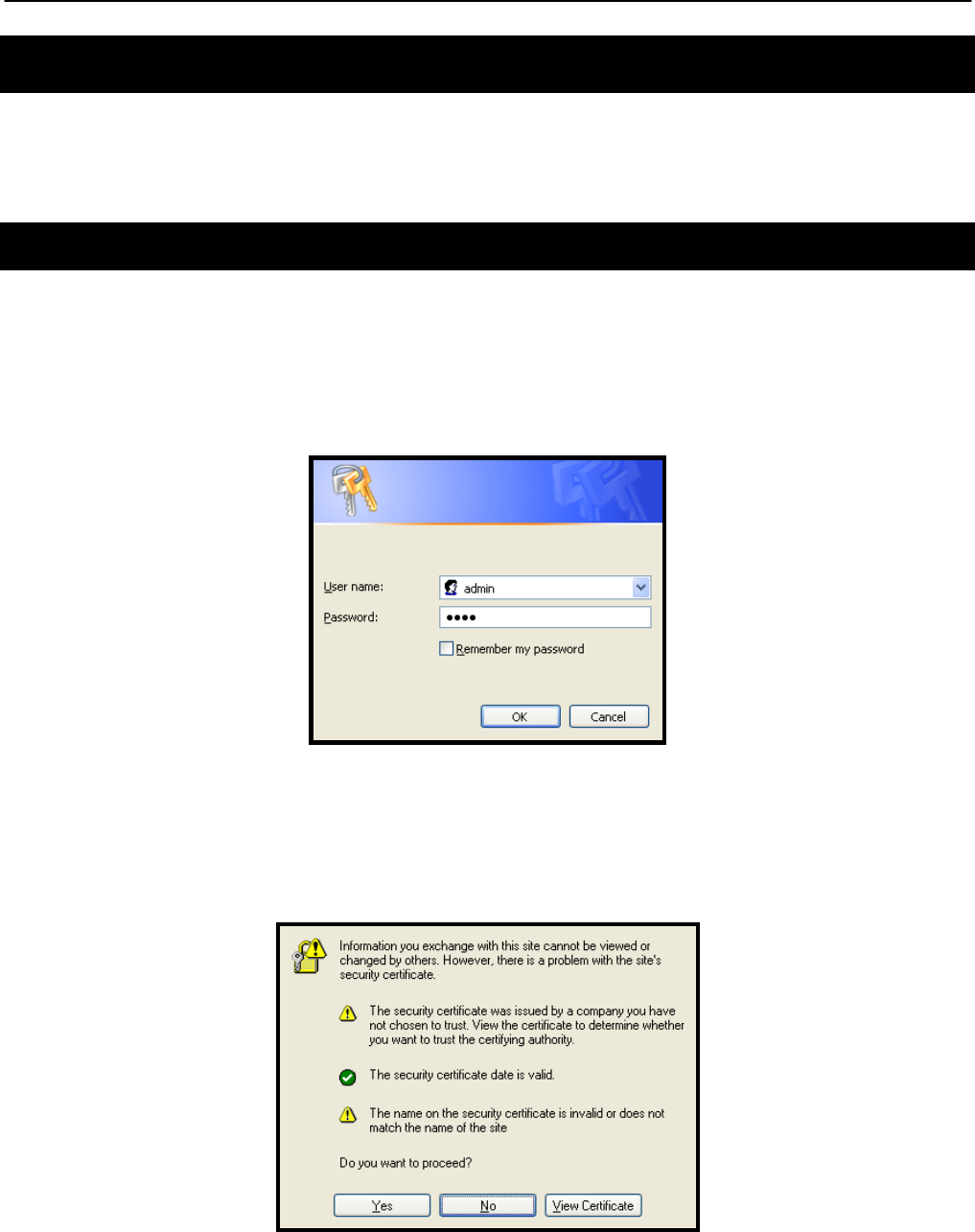
EnRoute500 using its Ethernet interface). When you enter this URL, you will be prompted for a
login and password. The default login and password used for the web interface are ‘admin’
and ‘default’, respectively.
Figure 5. Login window for web interface
Since the certificate used in establishing the secure link to the EnRoute500 has not been
signed by a Certification Authority (CA), your browser will most likely display one or more
warnings similar to those shown below. These warnings are expected and can be disregarded.
Figure 6. Certificate warning
Chapter 3: Using the Web Interface
TR0153 Rev. E1 20
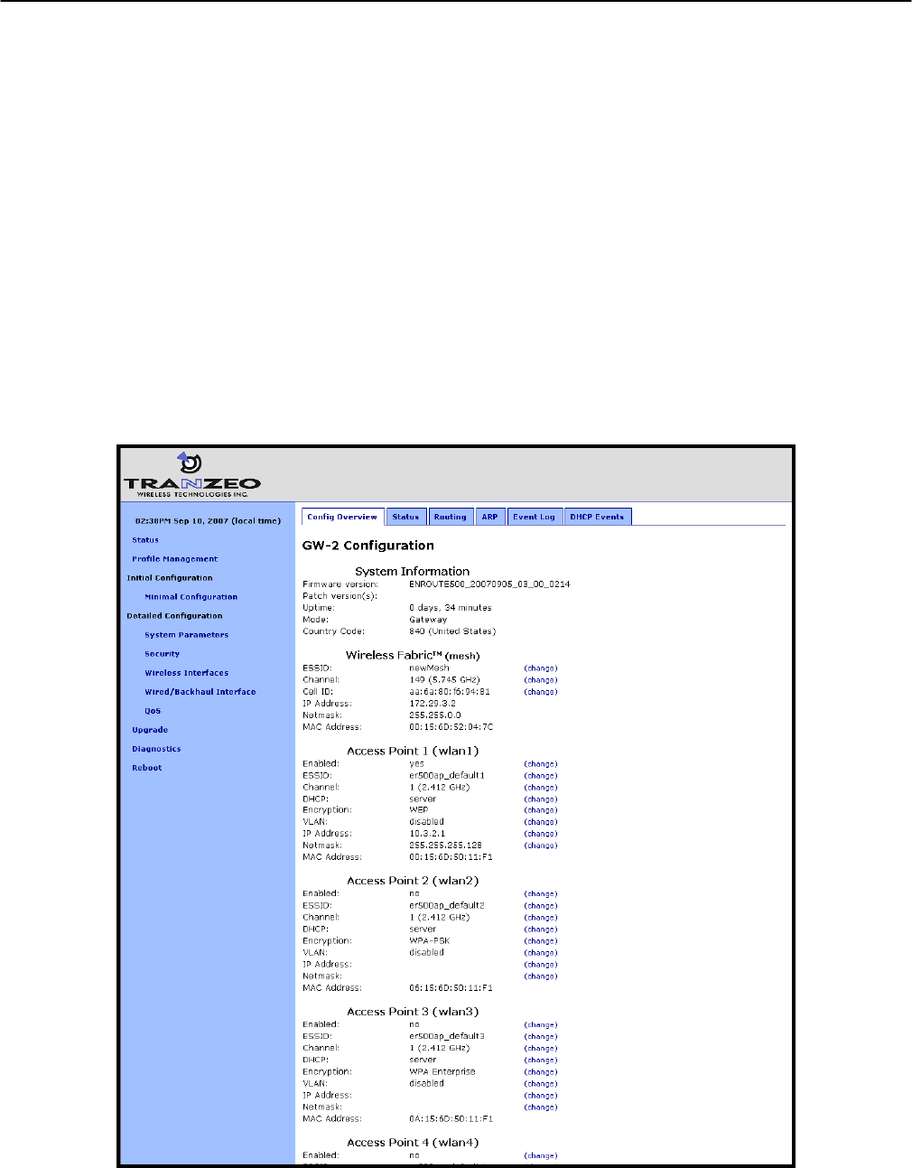
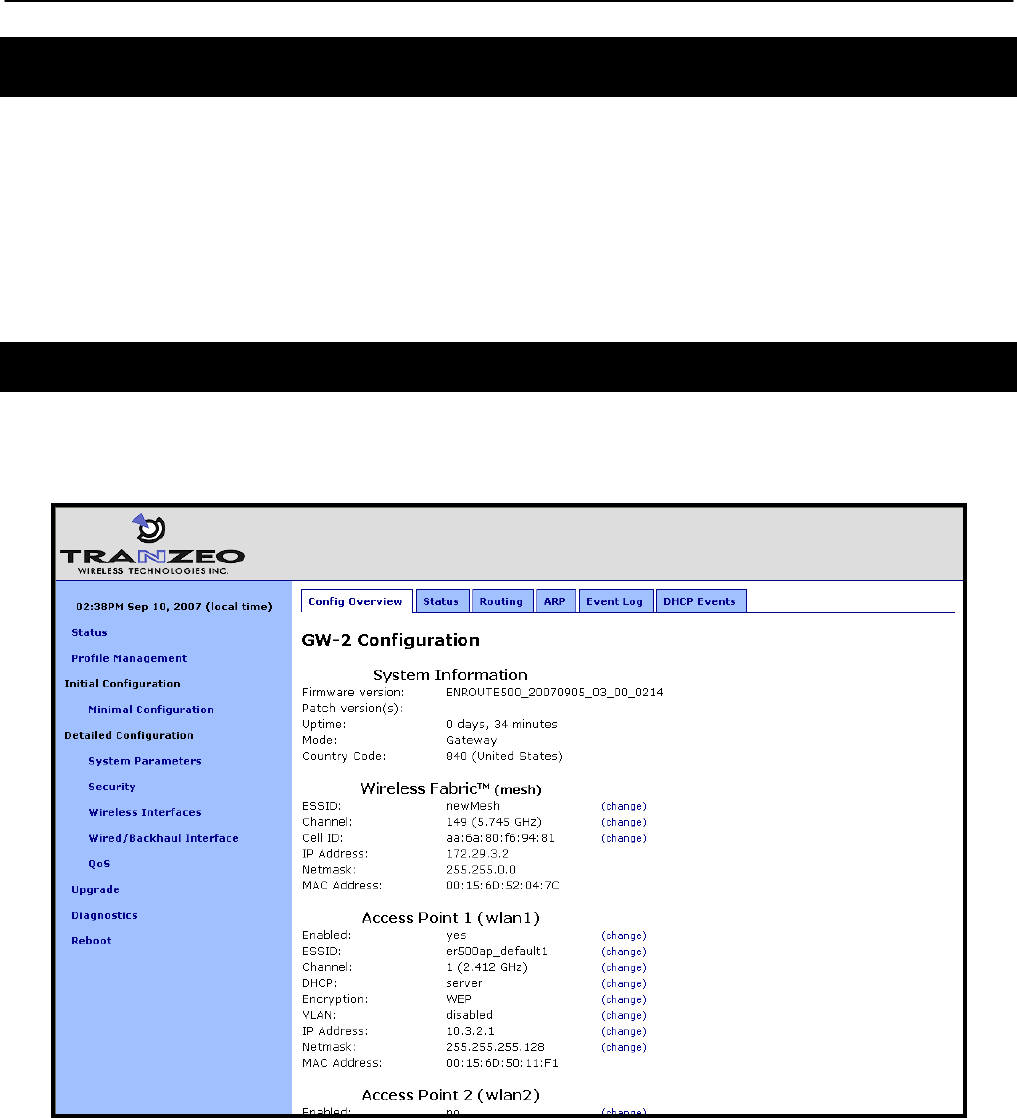
A configuration overview page is loaded by default after the login process has been completed.
This page contains the following information
• Firmware version and list of installed patches
• System uptime
• System mode of operation (gateway or repeater)
• Mesh channel and ESSID
• IP addresses, netmask, and MAC addresses for each client access interface
• Status, channel, ESSID, and encryption type for each virtual access point interface
• VLAN status and ID for all interfaces
• Ethernet interface use (client access or backhaul)
To access the status page from any other page in the web interface, click on the “Status” link
in the navigation bar that appears on the left side of the web interface.
Figure 7. Configuration overview page displayed when logging in
Chapter 3: Using the Web Interface
TR0153 Rev. E1 21
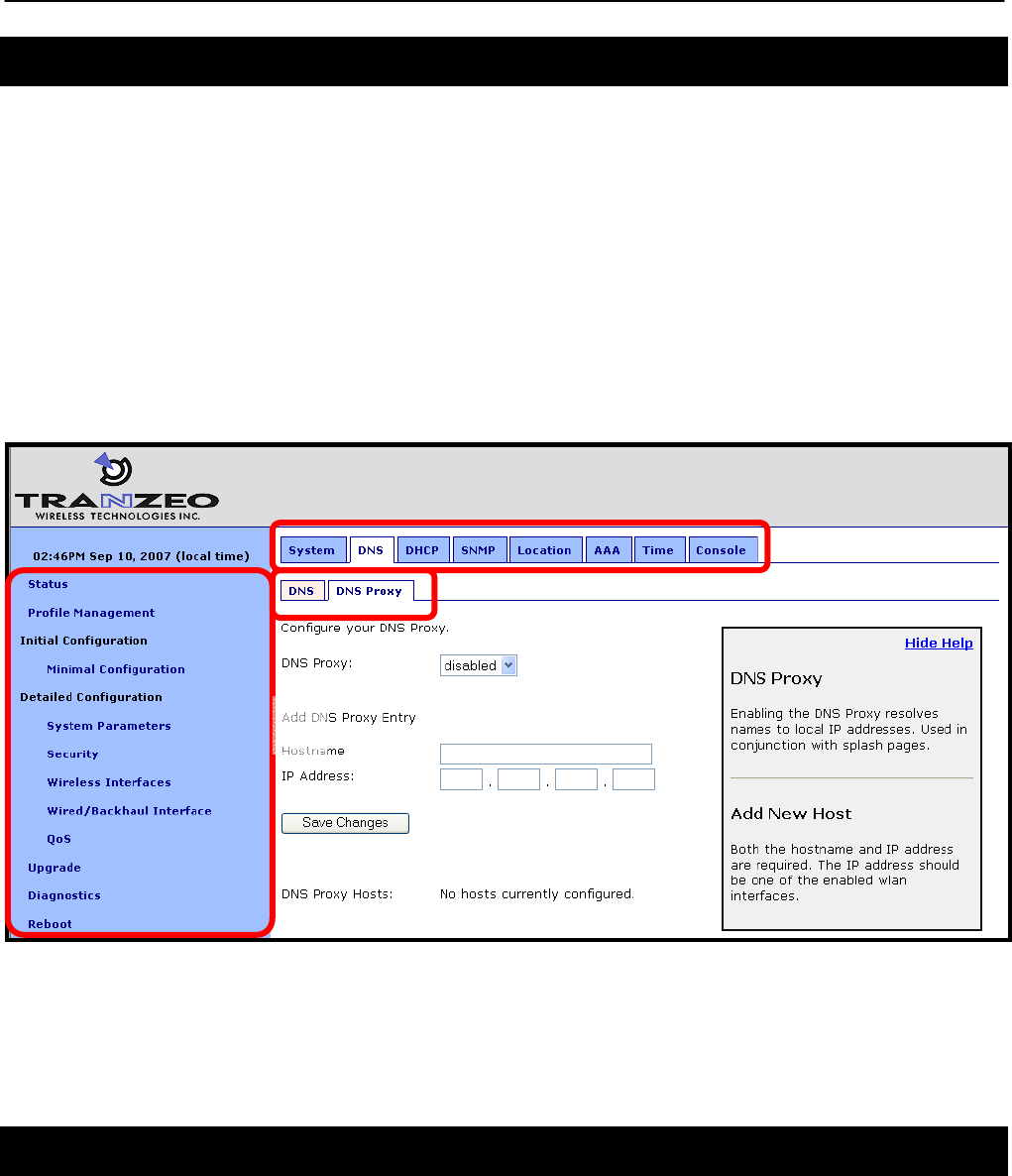
3.2 Navigating the Web Interface
The web interface uses a three-tiered navigation scheme.
1. The first tier of navigation is the navigation bar shown on the left side of the screen. This
navigation bar is displayed on all pages in the web interface and remains the same on
all pages.
2. The second tier of navigation is the primary row of tabs shown across the top of the
screen on many of the pages in the web interface. The labels in these tabs vary based
on which page is selected on the navigation bar.
3. The third tier of navigation is the second row of tabs shown below the first row. These
tabs are not present on all pages and their labels vary based on the selections made on
the navigation bar and the primary row of tabs.
Figure 8. Web interface navigation components
The time displayed at the top of the navigation bar is the current time of the PC used to log in
to the web GUI, not the time kept by the EnRoute500.
3.3 Setting Parameters
Many of the web interface pages allow you to set EnRoute500 operating parameters. Each
page that contains settable parameters has a “Save Changes” button at the bottom of the
page. When you have made your changes on a page and are ready to commit the new
1
2
3
Chapter 3: Using the Web Interface
TR0153 Rev. E1 22
configuration, click on the “Save Changes” button. It typically takes a few seconds to save the
changes, after which the page will be reloaded.
For the changes to take effect, the EnRoute500 must be rebooted. After a change has been
committed, a message reminding the user to reboot the EnRoute500 will be displayed at the
top of the screen.
Figure 9. Page showing "Save Changes" button and message prompting the user to reboot
3.4 Help Information
Help information is provided on most web GUI pages. The help information is shown on the
right-hand side of the page. The help information can be hidden by clicking on the ‘Hide Help’
link inside the help frame. When help is hidden, it can be displayed by clicking on the ‘Show
help’ link.
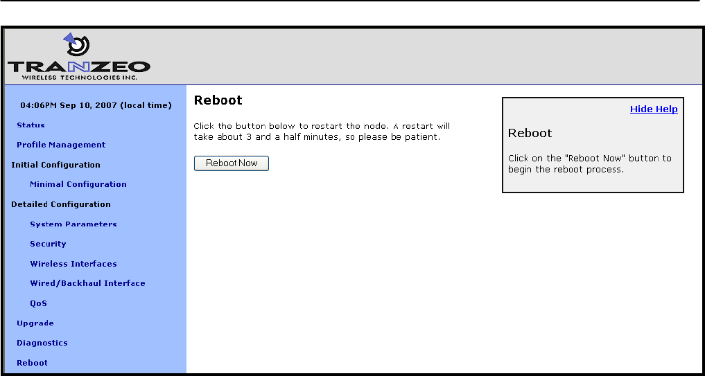
3.5 Rebooting
Click on the “Reboot” link on the left of the page and then click on the “Reboot Now” button to
reboot the EnRoute500. Any changes made prior to rebooting will take effect following
completion of the boot process.
It takes approximately 3 minutes for the device to reboot.
Chapter 3: Using the Web Interface
TR0153 Rev. E1 23
Figure 10. Rebooting the EnRoute500
Chapter 4: Using the Command Line Interface
TR0153 Rev. E1 24
4 Using the Command Line Interface
All configurable EnRoute500 parameters can be accessed with a Command Line Interface
(CLI).
The CLI allows you to:
• Modify and verify all configuration parameters
• Save and restore device configurations
• Reboot the device
• Upgrade the firmware
4.1 Accessing the CLI
The EnRoute500’s command-line interface (CLI) is accessible through its network interfaces
using an SSH client. Any of the network interfaces can be used to establish the SSH
connection to the EnRoute500. However, connecting through the Ethernet port is required for
devices that have not previously been configured.
Windows XP does not include an SSH client application. You will need to
install a 3rd-party client such as SecureCRT from Van Dyke software
(http://www.vandyke.com/products/securecrt) or the free PuTTY SSH client
(http://www.putty.nl/) to connect to an EnRoute500 using SSH.
When you log in to the EnRoute500, the CLI will present a command prompt. The shell timeout
is displayed above the login prompt. The CLI will automatically log out a user if a session is
inactive for longer than the timeout period. Section 8.14 describes how to change the timeout
period.
Shell timeout: 3 minutes.
Press '?' for help..
>
4.2 User Account
The user login used to access the EnRoute500 is ‘admin’. The procedure for changing the
password for this account is described in section 8.1.

Chapter 4: Using the Command Line Interface
TR0153 Rev. E1 25
4.3 CLI Interfaces
The CLI provides the user with a number of interfaces that contain related parameters and
controls. Some of these interfaces are hardware interfaces, such as Ethernet, while others are
virtual interfaces that contain a set of related parameters.
The available interfaces are:
• mesh0 – controls for the mesh radio
• wlan1, wlan2, wlan3, wlan4 – controls for the virtual APs supported by the EnRoute500
• eth0 – controls for the Ethernet interface
• firewall – controls firewall settings for client device, mesh device and mesh network access
• qos – controls Quality of Service (QoS) settings
• version – displays version information for the installed firmware
• system – system settings
The currently selected interface is shown as part of the command prompt. For example, when
the mesh interface is selected, the command prompt will be
mesh0>
After logging in, no interface is selected by default. Before setting or retrieving any parameters,
an interface must be selected.
4.4 CLI Features
The CLI has a number of features to simplify the configuration of the EnRoute500. These
features are explained in the following sub-sections.
4.4.1 Control of the Cursor
The cursor can be moved to the end of the current line with Ctrl+E. Ctrl+A moves it to the
beginning of the line.
4.4.2 Cancel a Command
Ctrl+C cancels the input on the current command line and moves the cursor to a new, blank
command line.

Chapter 4: Using the Command Line Interface
TR0153 Rev. E1 26
4.4.3 Searching the Command History
The command history can be searched by pressing Ctrl+R and entering a search string. The
most recently executed command that matches the string entered will be displayed. Press
‘Enter’ to execute that command.
4.4.4 Executing a Previous Command
By using the up and down arrow keys you can select previously executed commands. When
you find the command you wish to execute, you can either edit it or press ‘Return’ to execute it.
4.5 CLI Commands
The usage of all CLI commands is explained in the following subsections. The command
syntax used is
command <mandatory argument>
command [optional argument]
4.5.1 ‘?’ command
Syntax ?
Description Pressing ‘?’ at any time in the CLI will display a help menu that provides an
overview of the commands that are described in this section. It is not
necessary to press ‘Enter’ after pressing ‘?’.
4.5.2 ‘whoami’ command
Syntax whoami
Description Displays the name of the user you are logged in as.

Chapter 4: Using the Command Line Interface
TR0153 Rev. E1 27
4.5.3 ‘help’ command
Syntax help [command|parameter]
where the optional argument is either one of the CLI commands
(“[command]”) or a parameter in the currently selected interface
(“[parameter]”).
Description When no argument follows the help command, a help menu showing a list
of available commands is displayed. When a command is supplied as the
argument, a help message for that particular command is displayed. When
a parameter in the current interface is specified as the argument, help
information for it is displayed.
Example help get
will display the help information for the ‘get’ command. With the ‘sys’
interface selected
sys> help scheme
displays help information about that ‘scheme’ parameter, as shown below
scheme : wireless node type
4.5.4 ‘show’ command
Syntax show
Description Displays all available interfaces. An interface in this list can be selected
with the ‘use’ command.

Chapter 4: Using the Command Line Interface
TR0153 Rev. E1 28
4.5.5 ‘use’ command
Syntax use <interface>
where <interface> is one of the EnRoute500’s interfaces. A complete list of
interfaces is available with the ‘show’ command.
Description Selects an interface to use. By selecting an interface you can view and
modify the parameters associated with the interface.
Example use mesh0
will select the backhaul mesh radio interface and change the CLI prompt to
mesh0>
to reflect the interface selection.

Chapter 4: Using the Command Line Interface
TR0153 Rev. E1 29
4.5.6 ‘set’ command
Syntax set <parameter>=<value>
where <parameter> is the parameter being set and <value> is the value it
is being set to.
Description Sets a configuration parameter. Note that is only possible to set the
parameters for the currently selected interface. If the value of the
parameter contains spaces, the value must be surrounded by double
quotes (“ “).
If a valid 'set' command is entered, it will output its result and any effects on
other parameters. If changes are made to attributes of other interfaces as a
result of changing the parameter, these attributes are preceded by a '/' to
signify that they are in another interface.
Changing certain parameters will require the EnRoute500 to be rebooted.
Example With the ‘sys’ interface selected
set id.node=2
will set the node ID to 2, while
set id.mesh=1
will have an impact on a larger number of parameters as can be seen in
the output below.
id.mesh : 1
private.nets.default : "172.29.0.0/16 10.1.0.0/16"
/mesh0.routes.static : 224.0.0.0/4,10.1.0.0/16
splash.local_network : "172.29.1.0/24 10.1.0.0/16"
/mesh0.cellid : 00:05:88:01:0a:01
/mesh0.ip.address : 172.29.1.7
Reboot needed.
Note that changes were made to variables in the ‘mesh0’ interface, as
indicated by the ‘/’ at the beginning of those lines.

Chapter 4: Using the Command Line Interface
TR0153 Rev. E1 30
4.5.7 ‘get’ command
Syntax get <parameter>
where <parameter> is the parameter whose value is being fetched.
Description Gets the value of one or more configuration parameters for the currently
selected interface. The ‘*’ character can be used to specify wildcard
characters. This allows multiple values to be fetched with a single
command.
Example With the ‘sys’ interface selected
get id.node
will return the node’s ID, while
get id.*
will return all parameters that begin with ‘id.’
sys.id.lanprefix = 10
sys.id.mesh = 4
sys.id.meshprefix = 172.29
sys.id.node = 7

Chapter 4: Using the Command Line Interface
TR0153 Rev. E1 31
4.5.8 ‘list’ command
Syntax list
Description Lists all parameters for the selected interface
Example With the ‘firewall’ interface selected
list
will display
firewall.gateway.enable : prevent uninitiated incoming connections
past the gateway?
firewall.node.allowc2c.eth0 : allow clients to see each other if
.role=access
firewall.node.allowc2c.wlan1 : allow clients to see each other if
.role=access
firewall.node.allowc2c.wlan2 : allow clients to see each other if
.role=access
firewall.node.allowc2c.wlan3 : allow clients to see each other if
.role=access
firewall.node.allowc2c.wlan4 : allow clients to see each other if
.role=access
firewall.node.
enable : firewall enabled? if not, nothing else
here matters.
firewall.node.tcp.allow.dest : tcp dest ports (space separated)
to allow to this node
firewall.node.tcp.allow.source : tcp source ports (space
separated) to allow to this node
firewall.node.u
dp.allow.dest : udp dest ports (space separated)
to allow to this node
firewall.node.udp.allow.source : udp source ports (space
separated) to allow to this node
4.5.9 ‘ping’ command
Syntax ping <IP address or hostname>
Description Pings a remote network device. Halt pinging with Ctrl+C
Example ping 172.29.1.1

Chapter 4: Using the Command Line Interface
TR0153 Rev. E1 32
4.5.10 ‘ifconfig’ command
Syntax ifconfig <eth0|wlan[0-4]>
Description Displays information, such as IP address and MAC address, for the
specified network interface.
Example ifconfig wlan1
will display
wlan1 Link encap:Ethernet HWaddr 00:15:6D:52:01:FD
inet addr:10.2.10.1 Bcast:172.29.255.255 Mask:255.255.0.0
UP BROADCAST RUNNING MULTICAST MTU:1500 Metric:1
RX packets:0 errors:0 dropped:0 overruns:0 frame:0
TX packets:2434 errors:0 dropped:0 overruns:0 carrier:0
collisions:0 txqueuelen:0
RX bytes:0 (0.0 b) TX bytes:233128 (227.6 Kb)
4.5.11 ‘route’ command
Syntax route
Description Displays the current route table.
4.5.12 ‘clear’ command
Syntax clear
Description Clears the screen

Chapter 4: Using the Command Line Interface
TR0153 Rev. E1 33
4.5.13 ‘history’ command
Syntax history
Description Shows the command history since the EnRoute500 was last rebooted
Example After switching to the ‘wlan1’ interface, inspecting the ESSID setting, and
then changing it
history
will display
1: use wlan1
2: get essid
3: set essid=new_ap_essid

Chapter 4: Using the Command Line Interface
TR0153 Rev. E1 34
4.5.14 ‘!’ command
Syntax !<command history number>
!<string that matches start of previously-executed command>
!!
Description Executes a previously-executed command based either on a command
history number or matching a string to the start of a previously-executed
command. Note that there is no space between the ‘!’ and the argument.
The ‘history’ command shows the command history, with a number
preceding each entry in the command history. Use this number as an
argument to the ‘!’ command to execute that command from the history.
When a string is provided as an argument to the ‘!’ command, the string will
be matched against the beginning of previously-executed commands and
the most recently executed command that matches will be executed.
Use ‘!!’ to execute the last command again.
Example If the command history is as follows
1: use wlan1
2: get essid
3: set essid=new_ap_essid1
4: use wlan2
5: set essid=new_ap_essid2
the command
!1
will execute
use wlan1
The command
!use
will execute
use wlan2

Chapter 4: Using the Command Line Interface
TR0153 Rev. E1 35
4.5.15 ‘exit’ command
Syntax exit
Description Terminates the current CLI session and logs out the user
4.5.16 ‘quit’ command
Syntax quit
Description Terminates the current CLI session and logs out the user

Chapter 5: Initial Configuration of an EnRoute500
TR0153 Rev. E1 36
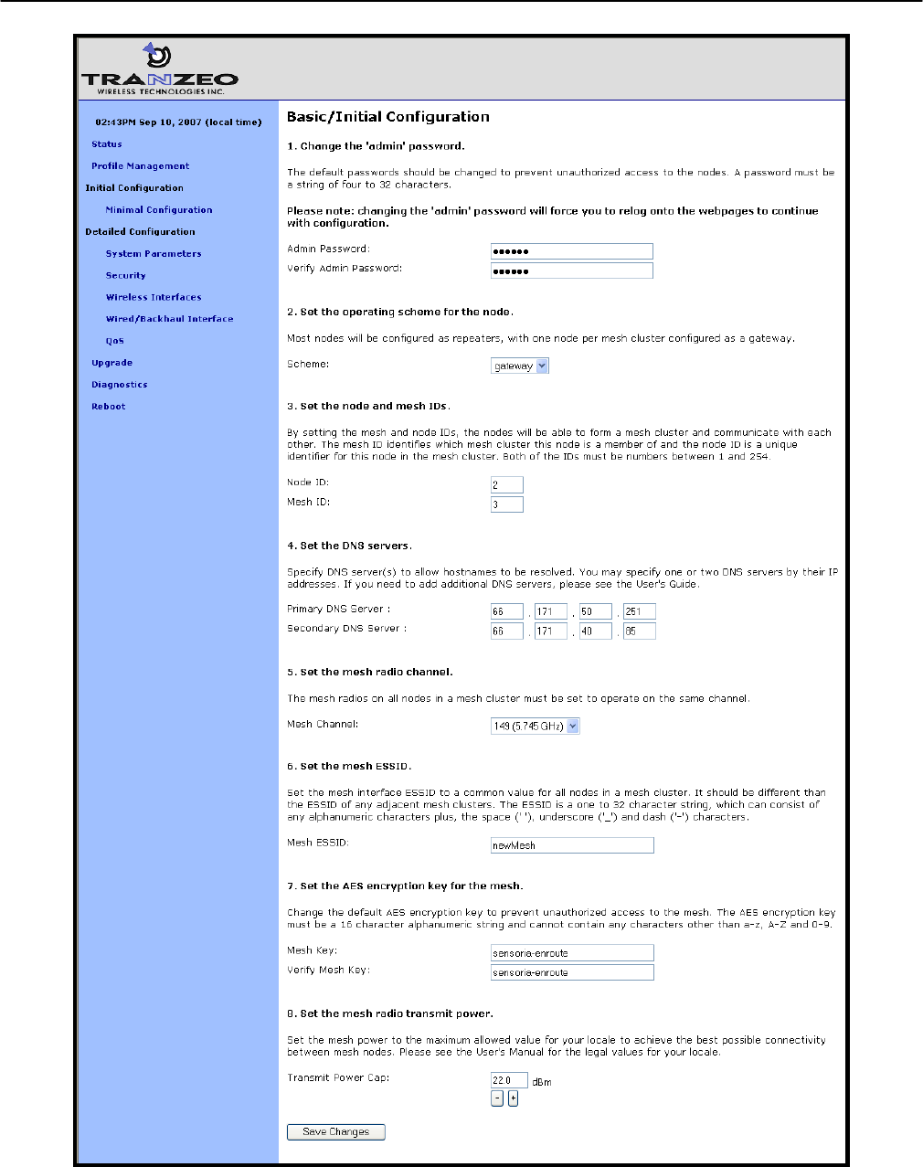
5 Initial Configuration of an EnRoute500
This user’s guide provides a comprehensive overview of all of the EnRoute500’s features and
configurable parameters. However, it is possible to deploy a network of EnRoute500s while
only changing a limited number of parameters. The list below will guide you through a minimal
configuration procedure that prepares a network of EnRoute500s for deployment.
1 Change the ‘admin’ password.
The default password should be changed to prevent
unauthorized access to the EnRoute500.
See section 8.1
2
Set the operating scheme for the EnRoute500
Most EnRoute500s will be configured as repeaters, with at least
one EnRoute500 per mesh neighborhood configured as a
gateway.
See section 8.2
3 Set the node and mesh IDs
The node and mesh IDs uniquely identify an EnRoute500. See section 8.3
4 Set the DNS servers
Specify DNS servers to allow hostnames to be resolved. See section 8.6
5 Set the mesh radio channel
The mesh radios on all EnRoute500s in a mesh neighborhood
must be set to operate on the same channel.
See section 10.1
6
Set the mesh ESSID
Set the mesh interface ESSID to a common value for all
EnRoute500s in a mesh neighborhood. It should be different
than the ESSID for any adjacent mesh neighborhoods.
See section 10.2
7
Set the AES encryption key for the mesh
Change the default AES encryption key to prevent unauthorized
access to the mesh. The mesh encryption key must be the
same for all EnRoute500s in a mesh neighborhood.
See section 10.3
8 Set the mesh radio transmit power
Set the mesh power to the maximum allowed value to achieve
the best possible connectivity in the mesh.
See section 10.4
In addition to setting the parameters on the “Minimal Configuration” page,
OnRamp access should be disabled after initial programming. See section
8.16 for instructions on how to enable OnRamp access to the EnRoute500.

Chapter 5: Initial Configuration of an EnRoute500
TR0153 Rev. E1 37
After these settings have been changed, the EnRoute500s will be able to form a mesh
neighborhood so that further configuration can be done from a central location, using the
connectivity of provided by the mesh. This minimal configuration must be performed prior to
deployment, but all other configuration can be carried out after deployment.
To simplify initial configuration, the web GUI has a page that allows the user to change all the
parameters listed in this section on a single page. This page can be accessed by clicking on
the ‘Minimal configuration’ link in the web interface navigation bar on the left side of the web
interface.
Chapter 5: Initial Configuration of an EnRoute500
TR0153 Rev. E1 38
Figure 11. Initial configuration web page
Chapter 6: Status Information
TR0153 Rev. E1 39
6 Status Information
Multiple web interface pages that display status information about the EnRoute500 and client
devices attached to it are available. These web pages are accessible by clicking on the
“Status” link in the navigation bar and then selecting the appropriate tab shown at the top of
the page.
The status information is not accessible through the CLI.
6.1 Configuration Overview Page
The main status page, which is displayed when clicking on “Status” in the navigation bar and
when logging in, is the “Config Overview” page.
Figure 12. Partial configuration overview page
The configuration overview page shows a summary of settings for the mesh interface, the
virtual access point interfaces, and the wired interface. The firmware version, uptime of the
device, and its operating mode are also displayed.

Chapter 6: Status Information
TR0153 Rev. E1 40
Links labeled “(change)” are shown next to the settable parameters. These links take you to
the appropriate page to change the setting.
6.2 Interface Status
Traffic and neighbor information for the mesh, virtual AP, and wired interfaces are available on
the “Status” tab of the “Status” page. Select the appropriate interface for which you wish to
view information from the row of tabs below the primary tab row.
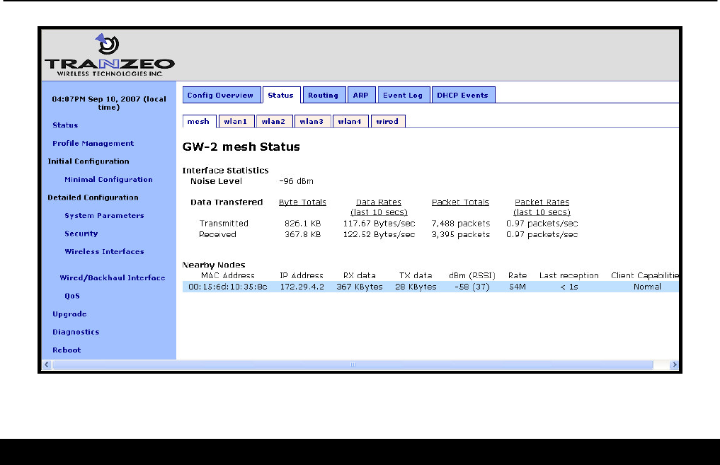
6.2.1 Mesh and Virtual AP Interfaces
The sub-tabs display status information about the mesh and virtual AP interfaces. Data
statistics information for the interface are displayed, showing received and transmitted data in
terms of bytes and packets.
In the case of the “mesh” sub-tab, the neighboring mesh devices that this device can
communicate directly with are displayed. On the “wlan” sub-tabs, the client devices connected
to the virtual APs are displayed. The following information is displayed for each mesh neighbor
or client device:
• MAC address
• IP address
• Quantity of data received from the neighbor/client device and transmitted to the
neighbor/client device
• Received signal strength (RSSI) in dBm and in parentheses the associated signal level
based on a noise floor of -95dBm
• Time since last reception from the device
• A summary of the capabilities of the client device’s radio card
Chapter 6: Status Information
TR0153 Rev. E1 41
Figure 13. Mesh status information
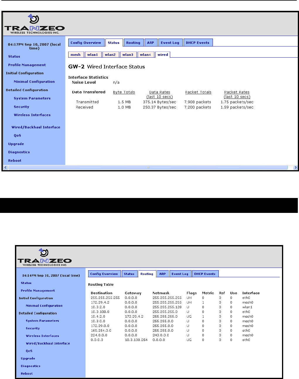
6.2.2 Wired Interface Status
The wired interface status pages is similar to the wireless interface status pages, with the
exception that it only displays summary information for the interface and does not break down
data transferred on a per-device basis.
Chapter 6: Status Information
TR0153 Rev. E1 42
Figure 14. Wired interface status information
6.3 Routing Table
The routing table used by the device can be displayed by selecting the “Routing” tab on the
“Status” page.
Figure 15. Routing table
Chapter 6: Status Information
TR0153 Rev. E1 43
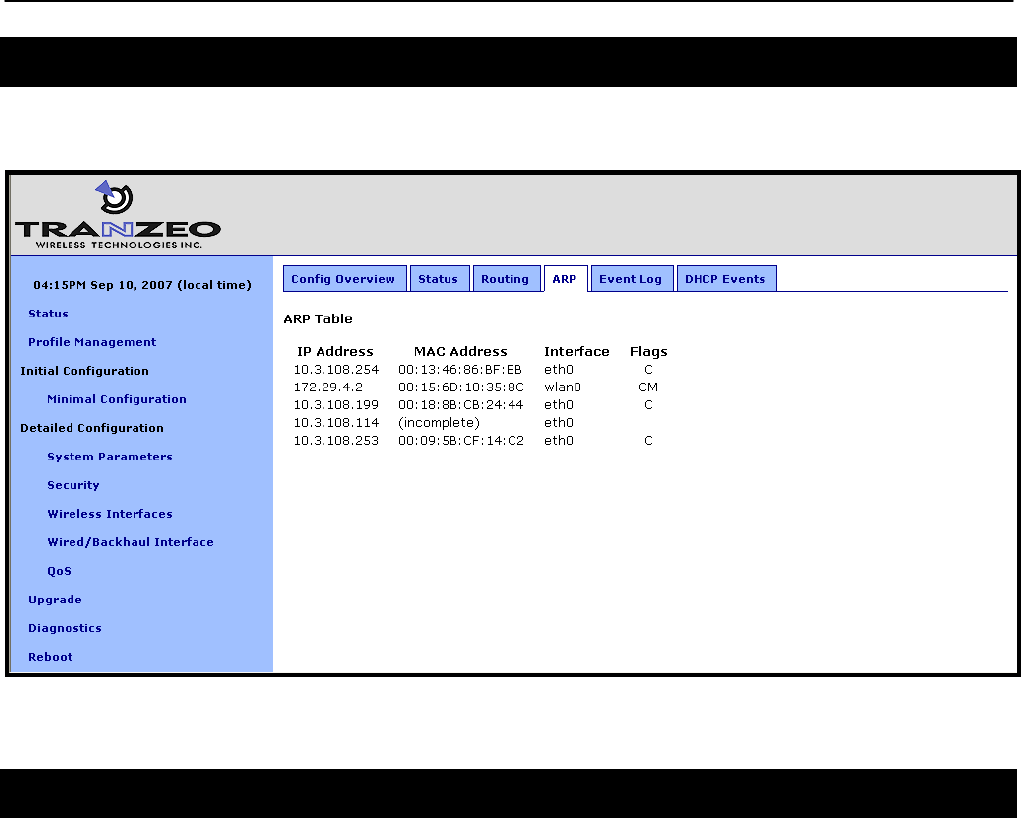
6.4 ARP Table
The device’s ARP table can be displayed by selecting the “ARP” tab on the “Status” page.
Figure 16. ARP table
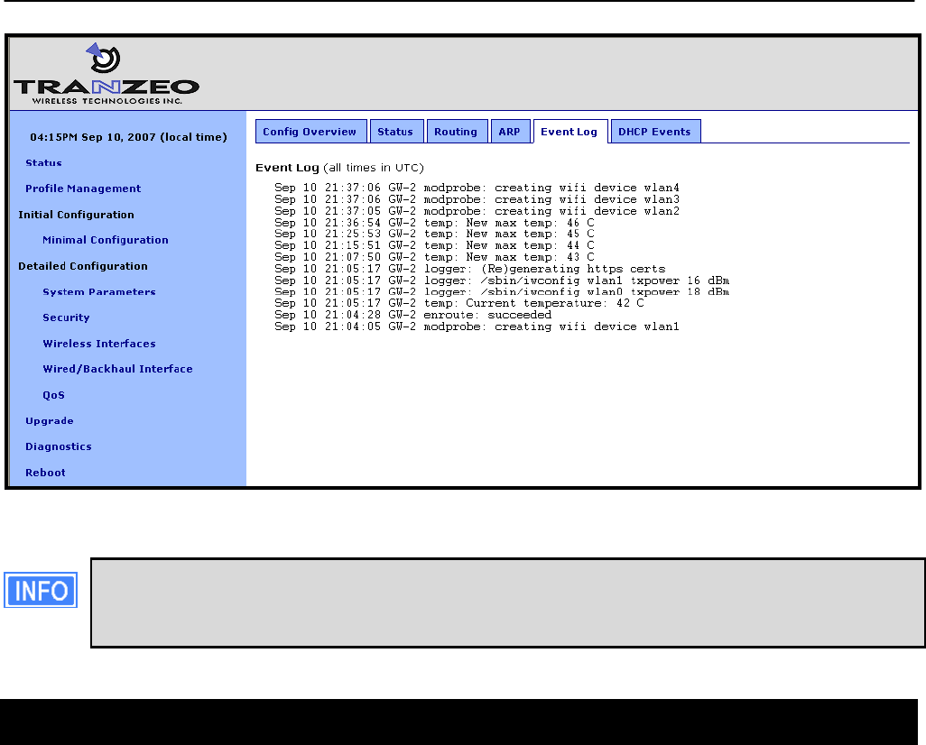
6.5 Event Log
The main system log for the device is accessible by selecting “Event Log” on the “Status”
page. The log is displayed in reverse chronological order, with the last recorded event
appearing at the top of the page.
Chapter 6: Status Information
TR0153 Rev. E1 44
Figure 17. Event log
The time reported in the Event Log corresponds to the time maintained by the
EnRoute500and may not be consistent with that shown in the upper left corner of the
webpage as this is the time maintained by the computer running the web browser.
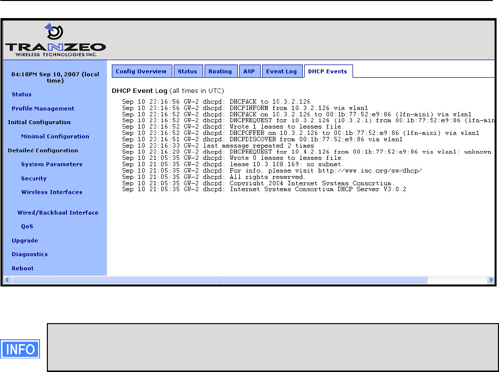
6.6 DHCP Event Log
The log of DHCP-related events for the device is accessible by selecting “DHCP Events” on
the “Status” page. The log is displayed in reverse chronological order, with the last recorded
event appearing at the top of the page. All times in the log are in UTC time. Messages related
to both local and relayed DHCP activity are displayed in the log.
Chapter 6: Status Information
TR0153 Rev. E1 45
Figure 18. DHCP event log
The time reported in the DHCP Log corresponds to the time maintained by the
EnRoute500and may not be consistent with that shown in the upper left corner of the
webpage as this is the time maintained by the computer running the web browser.
Chapter 7: Configuration Profile Management
TR0153 Rev. E1 46
7 Configuration Profile Management
Configuration profiles describe an EnRoute500’s configuration state and can be created to
simplify the provisioning and management of devices. The EnRoute500 supports the following
configuration profile-related actions:
• Saving the current configuration as a configuration profile
• Loading, or applying, a configuration profile stored on an EnRoute500 to the device
• Downloading a configuration profile stored on the EnRoute500 to a computer
• Uploading a configuration profile from a computer to the EnRoute500
• Deleting a configuration profile stored on the EnRoute500
Currently configuration profile management is only supported via the web interface.
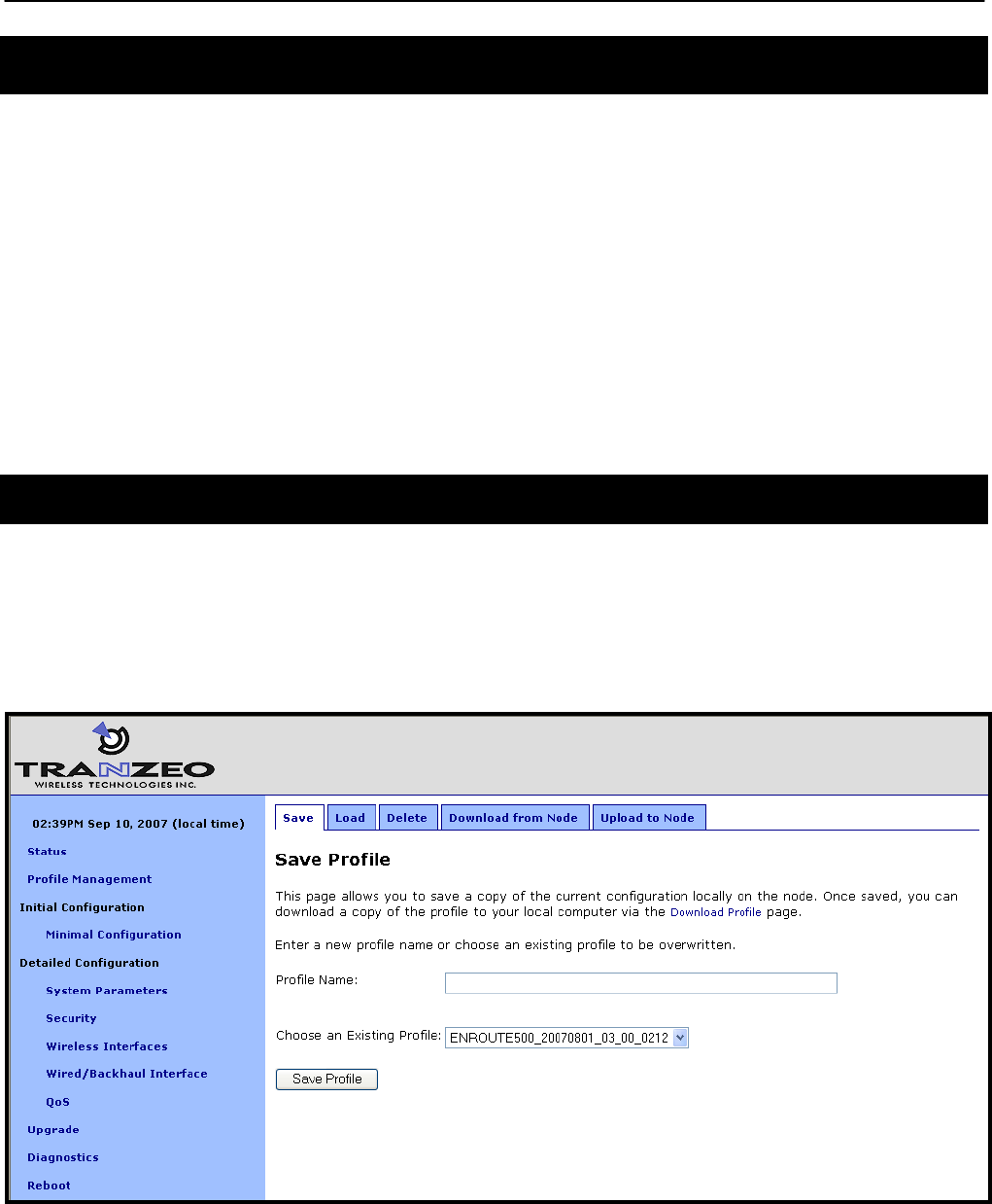
7.1 Saving the Current Configuration
The current configuration can be saved on the “Save” tab on the “Profile Management” page.
Enter a profile name or select an existing profile name from the list of existing configurations,
and then click on “Save Profile”. The saved profile is stored locally on the EnRoute500 and will
appear in the “Existing profiles” text box. Use the “Download from Node” tab to download it to a
different device.
Figure 19. Save a configuration profile
Chapter 7: Configuration Profile Management
TR0153 Rev. E1 47
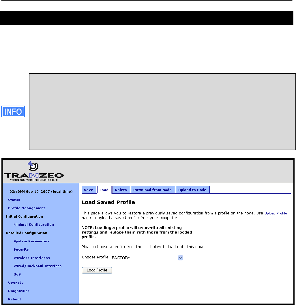
7.2 Load a Configuration Profile
A configuration stored on the EnRoute500 can be applied using the “Load” tab on the “Profile
Management” page. This profile must either have been saved earlier or uploaded to the
EnRoute500. Choose a profile name from the “Existing Profiles” box and then click on “Load
Profile”. It is necessary to reboot the EnRoute500 for the loaded profile settings to take effect.
A number of default configuration profiles are available on the EnRoute1000. There
is a “FACTORY” profile, which contains the default settings for the firmware version
that is installed. By applying this profile, an EnRoute500 will revert to the default
settings for that particular firmware version. If the EnRoute500 firmware has been
upgraded, there will also be a profile with the same name as the firmware version,
e.g. ENROUTE500_20060419_00_00_0133. This profile contains the settings that
were set when the new firmware was installed. If you wish to roll back to the settings
that were originally set when a particular firmware version was installed, apply the
profile with the name that matches the firmware version name.
Figure 20. Load a configuration profile
Chapter 7: Configuration Profile Management
TR0153 Rev. E1 48
After loading the same profile to multiple EnRoute500s, at a minimum the
node ID of the devices must be changed if they are to operate on the same
mesh neighborhood. It is recommended that after the same profile is loaded
onto multiple EnRoute500s, the parameters in the minimal configuration web-
page are reviewed for each.
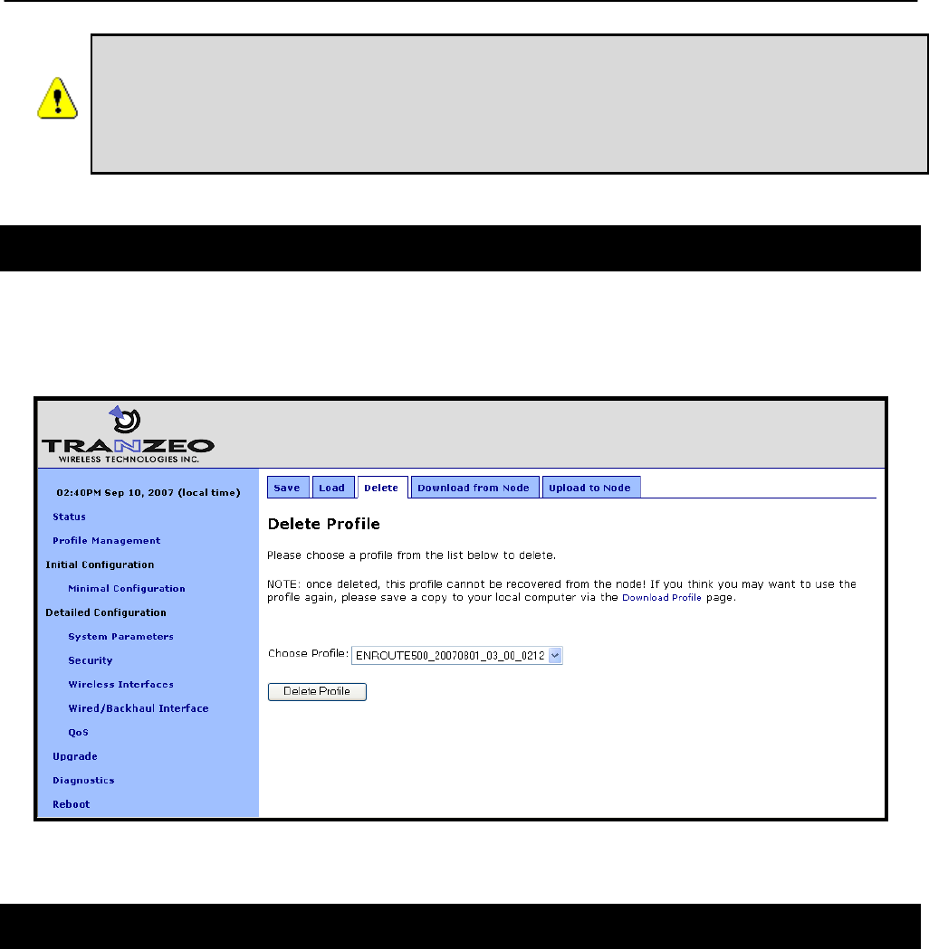
7.3 Delete a Configuration Profile
A locally-stored configuration profile can be deleted using the “Delete” tab on the “Profile
Management” page. Choose a profile to delete from the profile drop-down box on the page and
then click on “Delete Profile”.
Figure 21. Deleting a configuration profile
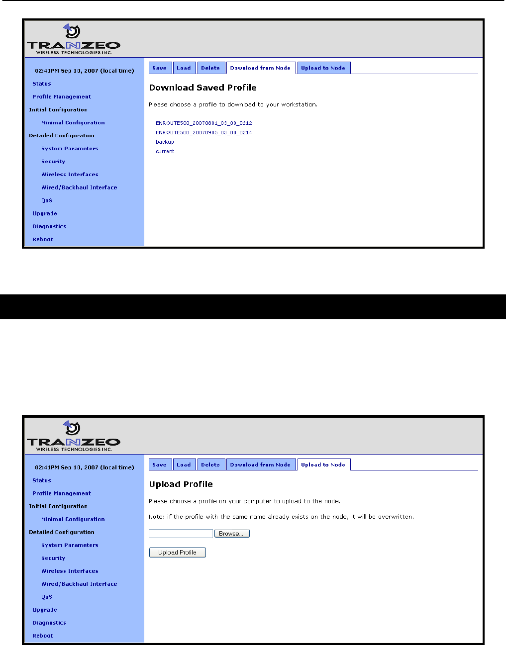
7.4 Downloading a Configuration Profile from an EnRoute500
A configuration profile can be download from an EnRoute500 using the “Download from node”
tab on the “Profile Management” page. The existing configuration profiles are listed on this
page. Click on the one that is to be downloaded to your computer and you will be given the
option to specify where the profile should be saved on the host computer.
Chapter 7: Configuration Profile Management
TR0153 Rev. E1 49
Figure 22. Downloading a configuration profile from an EnRoute500
7.5 Uploading a Configuration Profile to an EnRoute500
A configuration profile can be uploaded to an EnRoute500 using the “Upload to node” tab on
the “Profile Management” page. Use the “Browse” button to select a profile file on your host
computer for upload to the EnRoute500. Alternatively, enter the file name by hand in the text
box adjacent to the “Browse” button. Click on the “Upload Profile” button to upload the selected
file to the EnRoute500.
Figure 23. Uploading a configuration profile to an EnRoute500
Chapter 8: System Settings
TR0153 Rev. E1 50
8 System Settings
This section describes settings that are applicable to the overall operation of the EnRoute500,
but are not related directly to a particular interface.
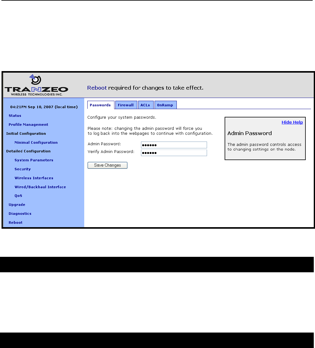
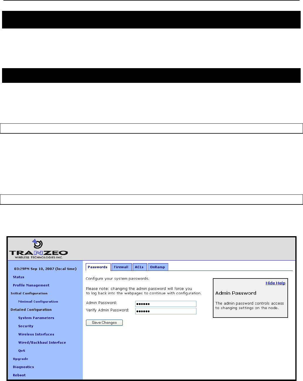
8.1 User Password
The password for the ‘admin’ user is configurable. The default password is ‘default’.
See section 2.4 for instructions on resetting the ‘admin’ password if it has been lost.
CLI
The password for the ‘admin’ user can be set using the ‘password.admin’ parameter in the
‘sys’ interface. The password will not be displayed when using the ‘get’ command with these
parameters. The example below shows how to set the ‘admin’ password using the CLI.
> use sys
sys> set password.admin=newpass
Web GUI
The ‘admin’ password can be changed via the web interface using the “Passwords” tab on the
“System Parameters” page.
Figure 24. Passwords page

Chapter 8: System Settings
TR0153 Rev. E1 51
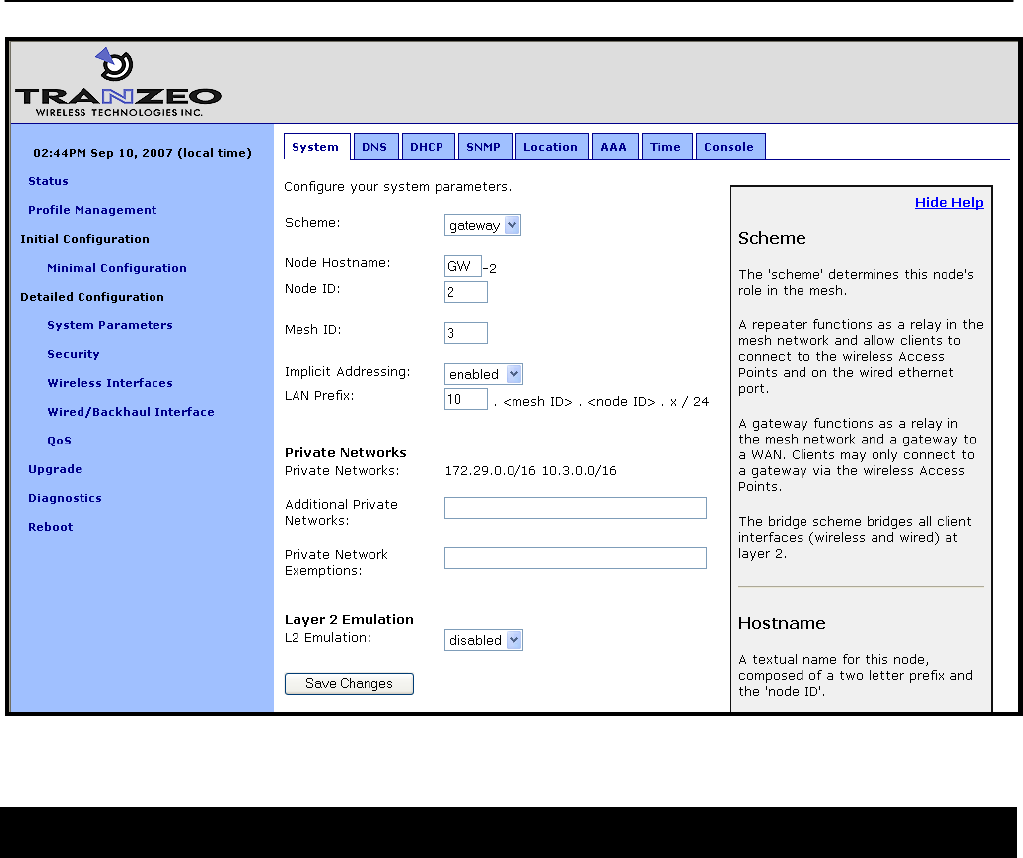
8.2 Operating Scheme
The operating scheme determines an EnRoute500’s role in the mesh network. Typically one of
two configurations will be used in a network:
• All EnRoute500s will be configured as repeater devices to create a stand-alone mesh
neighborhood
• At least one of the EnRoute500s in a mesh neighborhood will be configured as a gateway
device, with the remaining devices configured either as gateways or repeaters. The
gateway devices are connected to an external network using the devices’ Ethernet
interfaces. This network configuration will create an Internet extension network.
Mode Description Ethernet interface
Repeater
The EnRoute500 will function as a relay in the mesh network.
Client devices can connect to the EnRoute500 using both wired
(10/100 Ethernet) and wireless (built-in virtual APs) interfaces.
The EnRoute500 can provide IP addresses to clients on both the
wired and wireless interfaces.
Client devices can connect to
it. IP addresses can be
provided to client devices by a
DHCP server or be manually
configured.
Gateway
The EnRoute500 will function as a relay in the mesh network and
a gateway to a WAN. Client devices can only connect to the
EnRoute500 using the wireless (built-in virtual APs) interfaces.
The EnRoute500 can provide IP addresses to clients on the
wireless interface.
Used to connect the mesh
neighborhood to an external
network. The interface can be
provided an IP address by a
DHCP server or have a static
IP address assigned to it.
Table 5. EnRoute500 operating schemes
CLI
The EnRoute500’s operating scheme is set with the ‘scheme’ parameter in the ‘sys’ interface.
Valid values are ‘apgateway’ and ‘aprepeater’. For example, set the operating scheme to
gateway mode with:
> use sys
sys> set scheme=apgateway
Web GUI
The operating scheme can be set via the web interface using the “System” tab on the “System
Parameters” page.
Chapter 8: System Settings
TR0153 Rev. E1 52
Figure 25. Setting system parameters
8.3 Using Multiple Gateways
It is possible to have more than one gateway device per mesh neighborhood to provide
redundancy. The simplest method for creating a second gateway for a mesh neighborhood is
to save the profile from the existing gateway, apply it to the device that will become the second
gateway, and change at a minimum the following parameters on the new gateway:
• Node ID (see section 8.4)
• Base address, if using centralized DHCP server mode (see section 13.2.2)
• Ethernet IP configuration, if wired interface is not configured as a DHCP client (see
section 11.2)
It is also required that L2 MAC forwarding is enabled on all devices in the mesh when multiple
gateways are used (see 18.2 for more information on enabling L2 MAC emulation mode) No
additional configuration of WAN devices, e.g. routers, is necessary when using a multiple
gateway configuration.

Chapter 8: System Settings
TR0153 Rev. E1 53
It is important that all gateways for a common mesh neighborhood connect to the same LAN
segment/VLAN trunk, such that the gateways can receive each other's control messages over
the wired backhaul.
8.4 Mesh / Node ID
An EnRoute500 must be assigned mesh and node IDs before it is deployed as part of a mesh
neighborhood. Together, these values uniquely identify an EnRoute500 within a mesh
neighborhood and no two devices in a neighborhood are allowed to have the same
combination of mesh and node IDs.
The node and mesh IDs are part of the EnRoute500’s IP address as shown in Figure 26. The
allowable range for node IDs is 1 through 254, while mesh IDs must be in the range from 0 to
255.
172.29 . 12 . 107
Mesh prefix Mesh ID Node ID
Figure 26. EnRoute500 mesh interface IP address
CLI
The mesh ID is set with the ‘id.mesh’ parameter in the ‘sys’ interface as shown below.
> use sys
sys> set id.mesh=12
The node ID is set with the ‘id.node’ parameter in the ‘sys’ interface as shown below.
> use sys
sys> set id.node=107
Web GUI
The mesh and node IDs can be set via the web interface using the “System” tab on the
“System Parameters” page as shown in Figure 25.
8.5 Mesh Prefix
The mesh prefix parameter sets the first two octets of an EnRoute500’s mesh interface IP
address. It must be set the same for all devices in a given mesh neighborhood.
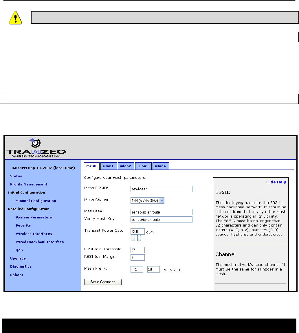
Chapter 8: System Settings
TR0153 Rev. E1 54
It is recommended that the mesh prefix default value of 172.29 is used.
CLI
The mesh prefix is set with the ‘id.meshprefix’ parameter in the ‘sys’ interface as shown in the
example below.
> use sys
sys> set id.meshprefix=172.29
Web GUI
The mesh prefix can be set via the web interface using the “Mesh” tab on the “Wireless
Interfaces” page.
Figure 27. Setting the mesh prefix
8.6 Internal and External Subnets
The EnRoute500s in a mesh neighborhood must be aware of which addresses are located
within the mesh and which are external to the mesh. The addresses that fall within the mesh
are considered internal, and those that are located on the WAN-side of the mesh
neighborhood’s gateway(s) are considered external.

Chapter 8: System Settings
TR0153 Rev. E1 55
The internal subnets include by default the mesh subnet, the client access interface subnets,
and, if centralized DHCP server mode is enabled, the DHCP client address space subnet.
These subnets are automatically listed as internal without requiring the user to specifically
identify them as such. It is possible to manually add other subnets to the list of subnets that
should be considered internal to the mesh.
The external subnets are all possible subnets that have not been defined as internal subnets.
The gateway will automatically add the subnet of the gateway interface to the list of external
addresses, even if it would normally be considered internal. Any external hosts that are
explicitly defined, such as the DNS servers, will be added to the list of external IP addresses,
even if their addresses would normally be considered to fall in internal subnets.
Repeater nodes will inform the gateway what subnets their client access interfaces are using,
and the gateway will then redistribute the combined internal/external subnet lists to the
repeaters so every device in the mesh neighborhood is consistent. This happens
automatically, without requiring user intervention or a reboot.
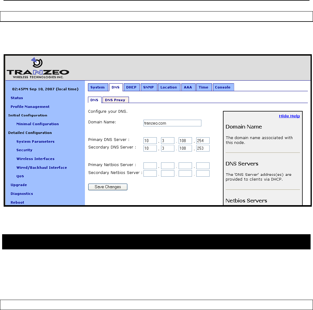
8.7 DNS / Domain Settings
At least one DNS server, accessible from the EnRoute500, must be specified for the device to
be able to resolve host names. This DNS server is also provided to client devices that acquire
an IP address from the local DHCP server on an EnRoute500.
DNS settings are automatically propagated from gateways to repeaters. Unless the
EnRoute500s are being used in a stand-alone network without any gateway, it is not
necessary to set the DNS server parameter on repeaters. They will get overwritten
by the values from the gateway(s) in the mesh neighborhood.
If a gateway device acquires DNS server information through DHCP on its wired interface, this
DNS server information will overwrite any manually set DNS server setting. The current DNS
settings will be passed to repeater devices that are in the mesh neighborhood that the gateway
is serving.
CLI
The DNS server(s) used by an EnRoute500 are specified with the ‘dns.servers’ parameter in
the ‘sys’ interface. To specify multiple DNS servers, list them as a space-delimited string
enclosed by quotes as shown in the example below
> use sys
sys> set dns.servers =”10.5.0.5 192.168.5.5”
Chapter 8: System Settings
TR0153 Rev. E1 56
Web GUI
A primary and secondary DNS server can be set via the web interface using the “DNS” tab on
the “System Parameters” page.
Figure 28. Setting the DNS and Netbios server(s)
8.8 DNS Proxy Configuration
DNS proxy entries can be added to an EnRoute500 to force local resolution of host names to
IP addresses for the hosts in the proxy list. Use of a DNS proxy list on the EnRoute500 is a
two step process, first populating the host name/IP address pairs, and then enabling DNS
proxy.
CLI
A list of hostname/IP address to be resolved locally can be specified using the ‘dnsproxy.hosts’
parameter in the ‘sys’ interface. If multiple hostname/IP address entries are specified, they
must be separated by semi-colons, as shown in the example below. DNS proxy must be
explicitly enabled using the ‘dnsproxy.enable’ parameter in the ‘sys’ interface after the list of
hosts has been specified.
> use sys
sys> set dnsproxy.enable=yes
sys> set dnsproxy.hosts=”server1.domain.com=10.0.0.1;server2.domain.com=10.0.0.129”
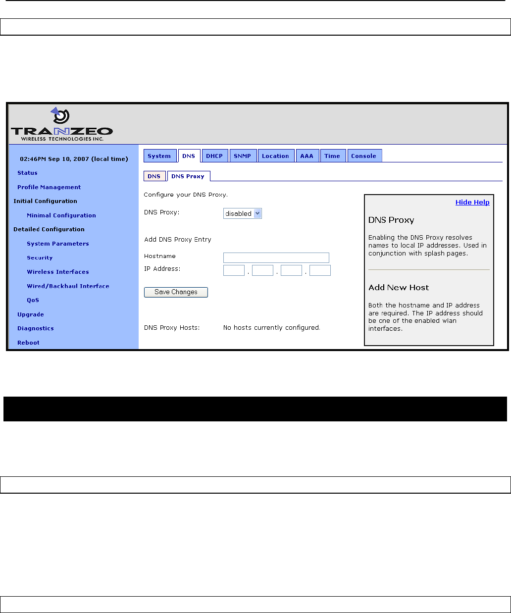
Chapter 8: System Settings
TR0153 Rev. E1 57
Web GUI
DNS proxy can be enabled on the “DNS Proxy” sub-tab on the “DNS” tab on the “System
Parameters” page as shown in Figure 29. Hostname/IP address pairs can be added on this
page as well.
Figure 29. Configuring DNS proxy
8.9 NetBIOS Server
The NetBIOS server parameter is used to define a NetBIOS server’s IP address that is
provided to client devices when they connect to the EnRoute500’s local DHCP server.
CLI
The NetBIOS server is set with the ‘netbios.servers’ parameter in the ‘sys’ interface. To specify
multiple NetBIOS servers, list them as a space-delimited string enclosed by quotes as shown
in the example below
> use sys
sys> set netbios.servers =”10.6.0.5 192.168.6.5”
Web GUI
A primary and secondary NetBIOS server can be set via the web interface using the “DNS” tab
on the “System Parameters” page (see Figure 28).

Chapter 8: System Settings
TR0153 Rev. E1 58
8.10 SNMP
The EnRoute500 supports SNMP.
The read-only and read-write passwords and the port that SNMP uses can be configured. A
contact person and device location can also be specified as part of the SNMP configuration.
CLI
The SNMP read-only and read/write passwords are set with the ‘snmp.community.ro’ and
‘snmp.community.rw’ parameters in the ‘sys’ interface. The example below shows how to set
these parameters.
> use sys
sys> set snmp.community.ro=”read-only_password”
sys> set snmp.community.rw=”read-write_password”
The SNMP port is set with the ‘snmp.port’ parameter in the ‘sys’ interface as shown below. By
default this parameter is set to “161”.
> use sys
sys> set snmp.port=161
The contact person and location of the device located via SNMP are set with the
‘snmp.contact. and ‘snmp.location’ parameters in the ‘sys’ interface as shown below.
> use sys
sys> set snmp.contact=”Joe Smith”
sys> set snmp.location=”123 Main St., Anytown, USA”
Web GUI
The SNMP-related parameters can be set on the “SNMP” tab on the “System” page (see
Figure 30).
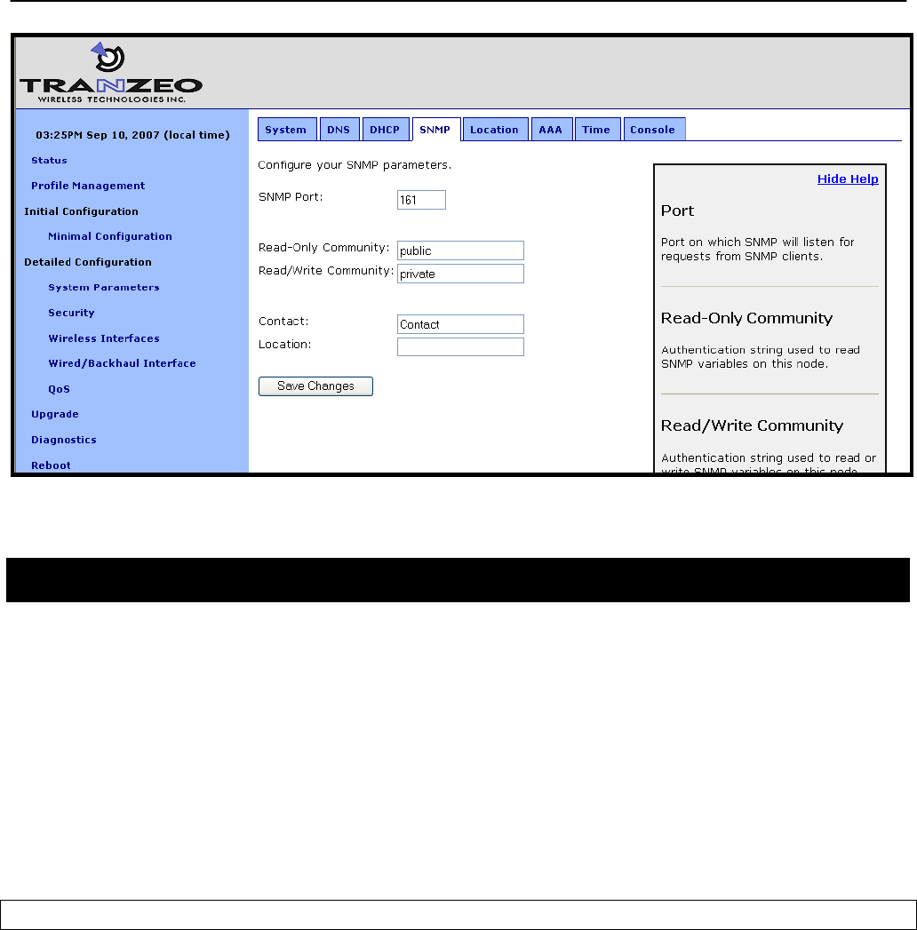
Chapter 8: System Settings
TR0153 Rev. E1 59
Figure 30. SNMP configuration
8.11 Location
Two types of device location information can be stored:
• Latitude/longitude/altitude
• Postal address or description a device’s location
Note that these values are not automatically updated and must be entered after a device has
been installed. Altitude is in meters. Latitude and longitude must be given as geographic
coordinates in decimal degrees, with latitude ranging from -90 to 90 (with negative being south,
positive being north) and longitude ranging from -180 to 180 (with negative being west, positive
being east).
CLI
The geographic location of the EnRoute500 can be stored in the following fields in the ‘sys’
interface:
• sys.location.gps.altitude
• sys.location.gps.latitude
• sys.location.gps.longitude
For example, you can set the latitude value as follows.
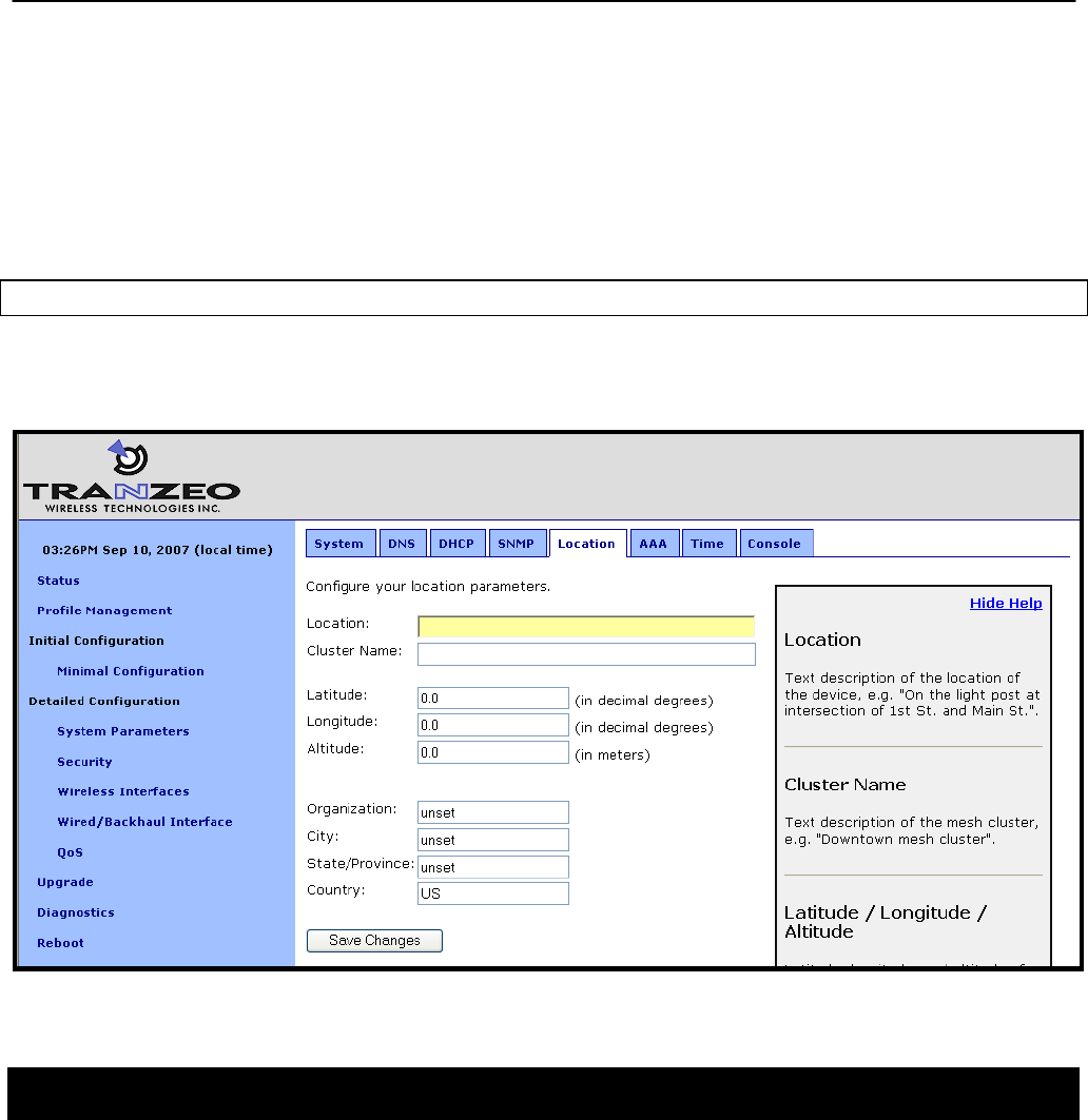
Chapter 8: System Settings
TR0153 Rev. E1 60
> use sys
sys> set location.gps.latitude=”34.01”
A description of the EnRoute500’s location can be stored in the ‘location.postal’ field in the
‘sys’ interface. For example, you can set the location value as shown below.
> use sys
sys> set location.postal=”Light post near 123 Main St., Anytown, CA”
Web GUI
The location information can be set via the web interface using the “Location” tab on the
“System Parameters” page.
Figure 31. Setting location and certificate information
8.12 Cluster Name
A name can be assigned to the mesh neighborhood, or cluster. This name will be displayed in
the upper right-hand corner of the web interface on all web interface pages. This name can be
used to easily identify which device or mesh neighborhood is being accessed with a particular
instance of the web interface. This name does not have any effect on the formation of the
mesh and can be different for devices in a mesh neighborhood.

Chapter 8: System Settings
TR0153 Rev. E1 61
CLI
The cluster name is set with ‘info.cluster’ parameter in the ‘sys’ interface. This parameter can
be set as shown in the example below.
> use sys
sys> set info.cluster=”Campus network”
Web GUI
The cluster name can be set via the web interface using the “Location” tab on the “System
Parameters” page (see Figure 31). Use the “Cluster Name” field to set the cluster name.
8.13 Certificate Information
A certificate for use with splash pages and the web interface is locally generated on the
EnRoute500. The information embedded in this certificate can be defined by the user. A new
certificate is automatically generated when the parameters describing the EnRoute500’s
location are changed. The specific location parameters to which the certificate is tied to are
listed in the sections below.
CLI
The information used in certificate generation can be set using the ‘organization’ parameters in
the ‘sys’ interface. These parameters are:
• sys.organization.name –name of organization (must be enclosed in quotes if it contains
spaces)
• sys.organization.city – city name (must be enclosed in quotes if it contains spaces)
• sys.organization.state – state name
• sys.organization.country – two-letter country abbreviation
Web GUI
The certificate information can be set via the web interface using the “Location” tab on the
“System Parameters” page (see Figure 31). Changing any of the Organization, City,
State/Province, or Country parameters will cause the certificate information to be recalculated.
8.14 Time Synchronization
An EnRoute500 configured as a gateway can be configured to synchronize its internal clock
with an external RFC-868-compliant time server. Devices configured as repeaters will
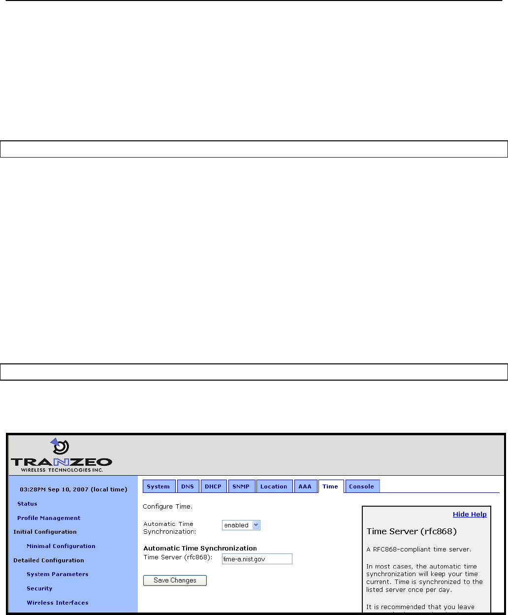
Chapter 8: System Settings
TR0153 Rev. E1 62
automatically synchronize their clocks with the mesh gateway. The delay between following
completion of booting and when a repeater synchronizes its clock can be configured. This
delay is designed so that if the entire mesh network is rebooted at the same time, the gateway
can first synchronize to the external time server, then each repeater, following the delay, will
synchronize with the gateway.
The time synchronization will ensure that proper time stamps are displayed for entries in the
event logs that are available on the web GUI’s “Status” page.
CLI
The time synchronization server for a gateway is set with the ‘time.rfc868.server’ in the ‘sys’
interface. The example below shows how to set the time synchronization server.
> use sys
sys> set time.rfc858.server=”your.time.server.here”
The ‘time.sync_delay’ parameter in the ‘sys’ interface sets the delay used by repeaters before
they synchronize their clocks with a gateway device.
> use sys
sys> set time.sync_delay=600
It is not possible to manually adjust the device time through the CLI. Please use the web GUI
to adjust it.
Web GUI
The synchronization mode and server can be set on the “Time” tab on the “System” page
when the device is configured as a gateway (Figure 32)
Figure 32. Automatic time synchronization
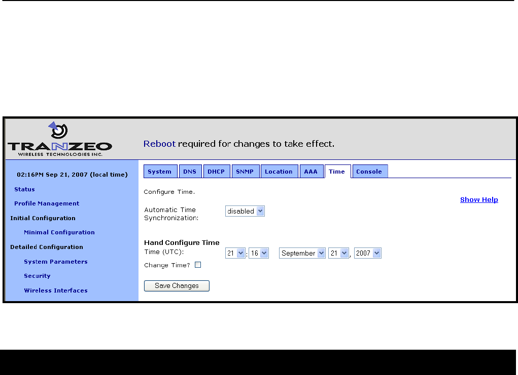
Chapter 8: System Settings
TR0153 Rev. E1 63
The synchronization delay and server can be set on the “Time” tab on the “System” page
when the device is configured as a repeater.
When automatic synchronization is disabled, the user can set the EnRoute500’s UTC time
(Figure 33). Enter the time using the available drop-down menus and check the “Change Time”
checkbox.
Figure 33. Setting the time manually
8.15 Web GUI Console
The web interface allows the user to set parameters that are not otherwise settable through the
web interface using a console interface. The console is available on the “Console” tab on the
“System” page.
CLI key/value pairs can be entered through the console. The key format used is “<interface
name>.<key>”. For example, “wlan1.channel” is the key to set the channel used by virtual AP
wlan1. To use the console, enter one or more key/value pairs in the large text box on the page,
either separating each pair with a space or placing each pair on its own line. Click on the
“Submit Commands” button to set the values entered in the text box.
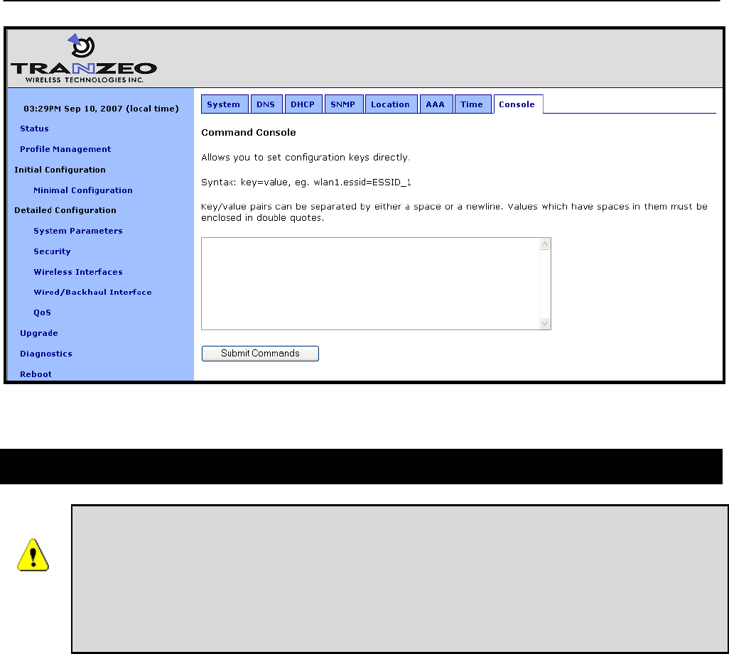
Chapter 8: System Settings
TR0153 Rev. E1 64
Figure 34. Web interface console
8.16 OnRamp Configuration Access
ONRAMP IS A PC-BASED TOOL THAT WILL BECOME AVAILABLE TO
SUPPORT INITIAL CONFIGURATION OF THE ENROUTE500. IT HAS NOT BEEN
RELEASED AT THE TIME OF THE WRITING OF THIS DOCUMENT. CHECK
WWW.TRANZEO.COM/ONRAMP FOR ONRAMP STATUS.
IT IS RECOMMENDED THAT ONRAMP CONFIGURATION ACCESS IS
DISABLED UNTIL THE TOOL IS MADE AVAILABLE.
The OnRamp utility provides network detection and configuration capabilities for EnRoute500s.
The configuration capabilities are only intended for initial configuration and for security
reasons, it is strongly recommended that OnRamp configuration capability is disabled after
initial configuration.
You can use the CLI, the web interface, or OnRamp to determine whether a device can be
configured from OnRamp. In OnRamp, the “Prog” column displays the programming capability
from OnRamp. A ‘Y” in this column indicates that OnRamp can configure the device, an ‘N’
indicates that it cannot.
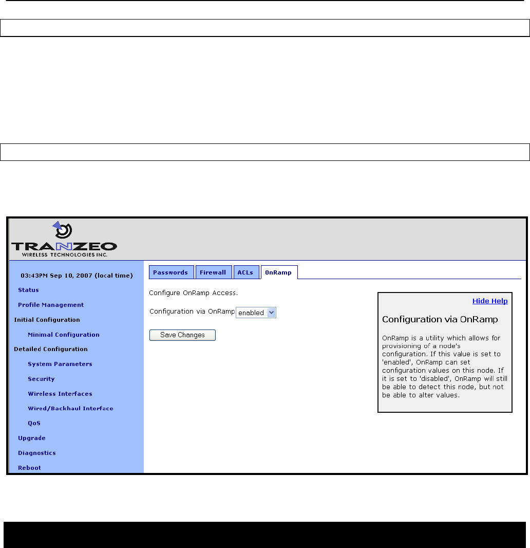
Chapter 8: System Settings
TR0153 Rev. E1 65
CLI
The OnRamp configuration capability is controlled by the ‘provisioning.enable’ parameter in the
‘sys’ interface. Set this parameter to ‘0’ to disable configuration through OnRamp, as shown in
the example below.
> use sys
sys> set provisioning.enable=0
Web GUI
The OnRamp configuration capability is set on the “OnRamp” tab on the “Security” page (see
Figure 35).
Figure 35. OnRamp configuration access
8.17 CLI Timeout
The CLI will automatically log out a user if the interface has remained inactive for a certain
length of time. The time, in seconds, that a shell must remain inactive before a user is
automatically logged out is set with the ‘shell.timeout’ parameter in the ‘sys’ interface, as
shown in the example below. The maximum idle time that can be set is 21600 seconds (6
hours).
> use sys
sys> set shell.timeout=300
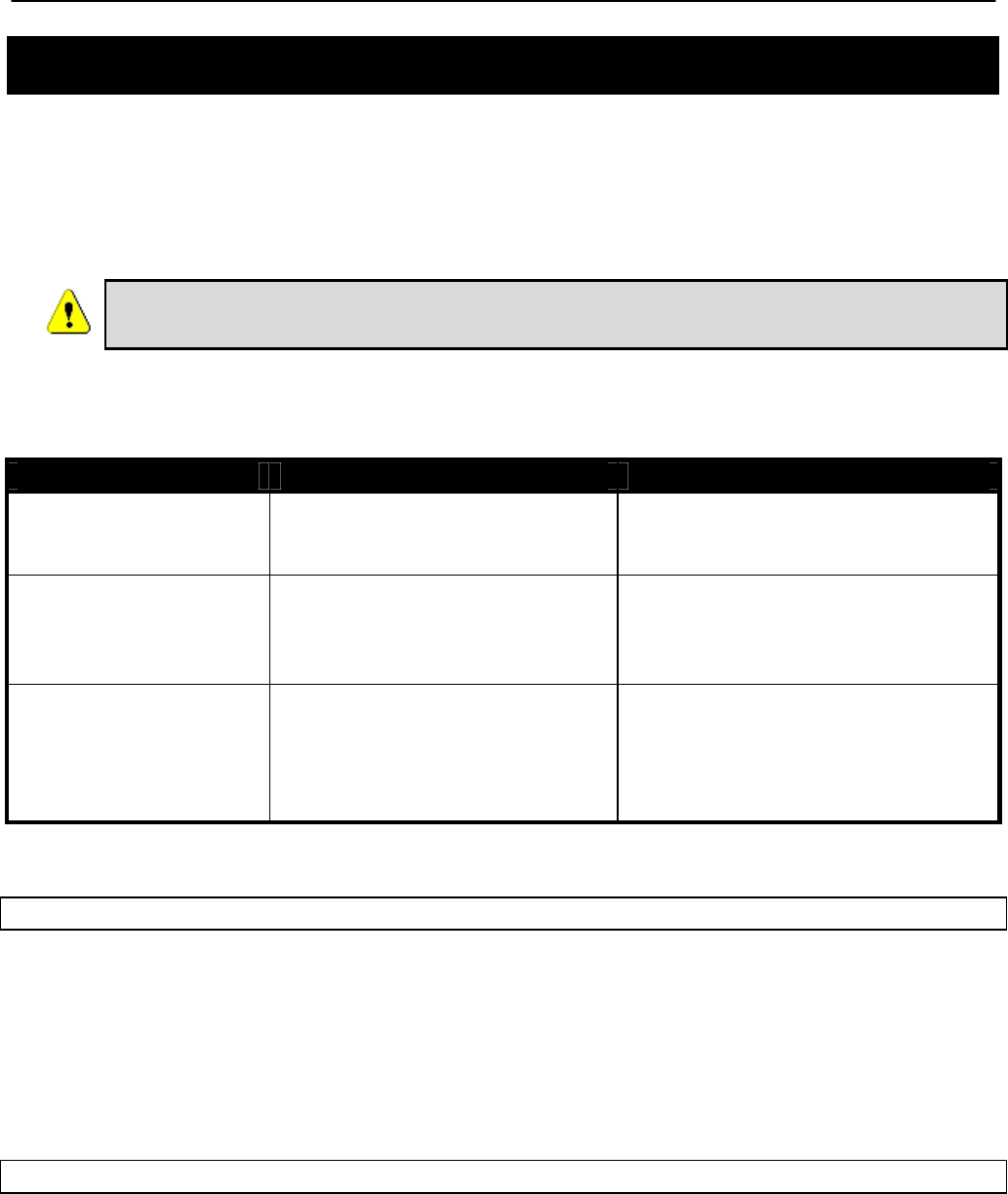
Chapter 9: Client Addressing Schemes
TR0153 Rev. E1 66
9 Client Addressing Schemes
The choice of client addressing scheme affects how EnRoute500 client access interface
addresses are assigned. The EnRoute500 can be configured to use an implicit addressing
scheme for its client access interfaces, or explicit addresses can be assigned to each client
access interface. The addressing scheme choice also affects what the addresses of clients will
be when the device is not operating in centralized DHCP server mode.
It is not possible to mix devices with implicit and explicit addressing schemes
in a common mesh neighborhood.
Table 6 compares how the behavior of the device differs depending upon the addressing
scheme that is chosen.
Feature Implicit addressing scheme Explicit addressing scheme
Client access interface
addresses
Derived from mesh ID, node
ID, and LAN prefix settings.
They cannot be directly set.
Can be set to arbitrary values, with
a few reserved address ranges
that cannot be used.
Size of client address
space
Each of the active client access
interfaces must share a class C
address space.
The address space size for each
client access interface can be set
independently and can be of
arbitrary size.
Default internal
subnets
Mesh subnet (typically
172.29.0.0/16), client subnet
(10.<mesh ID>.0.0/16, and
DHCP client address space
subnet
Mesh subnet (typically
172.29.0.0/16), 10.0.0.0/8, and
DHCP client address space
subnet
Table 6. Differences between explicit and implicit addressing schemes
CLI
The choice of implicit or explicit addressing scheme is controlled by the ‘implicit.enable’
parameter in the ‘mesh’ interface. Set this parameter to ‘yes’ to select implicit addressing and
to ‘no’ to select explicit addressing. The example below demonstrates how to select the implicit
addressing scheme.
> use mesh0
sys> set implicit.enable=yes
Web GUI
The addressing scheme is set with the “Implicit Addressing” drop-down menu on the “System”
tab of the “System” page. Set this to disabled to choose the explicit addressing scheme.
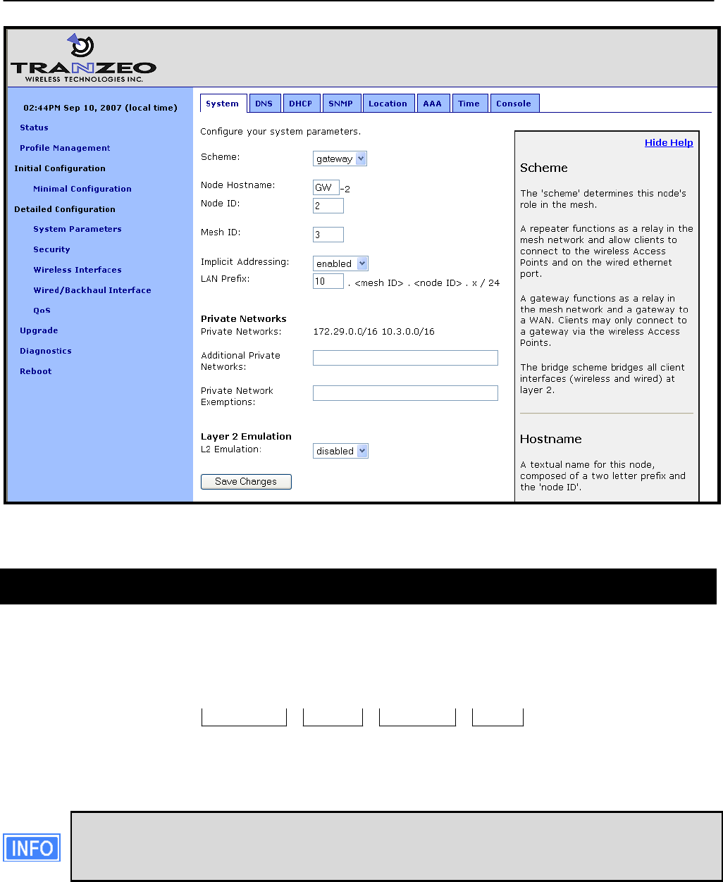
Chapter 9: Client Addressing Schemes
TR0153 Rev. E1 67
Figure 36. Setting the addressing scheme
9.1 Implicit Addressing Scheme
The implicit addressing scheme requires a class C network, which has a unique address within
a mesh, to be shared between all active client access interfaces. The subnet address space is
based on the mesh ID, node ID, and LAN prefix as shown in Figure 37.
Mesh ID Node ID
10 . 12 . 107 . 0
LAN prefix
Figure 37. Subnet address structure
If the EnRoute500 is operating in centralized DHCP server mode, the addresses
used for the implicit addressing scheme have no bearing on the addresses that are
assigned to client devices through DHCP.

Chapter 9: Client Addressing Schemes
TR0153 Rev. E1 68
The default division of the class C address space is shown in Table 7. It is possible to change
this configuration, assigning larger address spaces to certain interfaces if not all interfaces are
enabled.
Interface Interface address Broadcast address Client device address range
wlan1 subnet.1 subnet.127 subnet.2-126
wlan2 subnet.129 subnet.159 subnet.130-158
wlan3 subnet.161 subnet.191 subnet.162-190
wlan4 subnet.193 subnet.223 subnet.194-222
eth0 subnet.225 subnet.255 subnet.226-254
subnet = <id.lanprefix>.<id.mesh>.<id.node>
Table 7. Default subnet segmentation between interfaces
9.1.1 LAN Prefix
The LAN prefix parameter sets the first octet of the client access interface IP address. The
suggested values for the LAN prefix are 10 and 192. The LAN prefix must be the same for all
devices in a mesh neighborhood.
The LAN prefix parameter has no effect when an EnRoute500 is using the explicit addressing
scheme.
CLI
The LAN prefix is set with the ‘id.lanprefix’ parameter in the ‘sys’ interface as shown in the
example below.
> use sys
sys> id.lanprefix=10
Web GUI
The LAN prefix can be set via the web interface using the “System” tab on the “System
Parameters” page (see Figure 36).
9.1.2 Client Address Space Segmentation in Implicit Addressing Mode
As mentioned above, the client access interfaces must share a class C address space when
the EnRoute500 is using the implicit addressing scheme. The start address of each address
segment and its size can be set. The following restrictions are placed on the address segment
configuration:
• Each active client access interface must be assigned an address segment.

Chapter 9: Client Addressing Schemes
TR0153 Rev. E1 69
• The IP address range start address (‘ip.implicit.start.requested’ in the CLI) must be one of
the following values: 1, 33, 65, 97, 129, 161, 193, 225.
• The IP address range size (‘ip.implicit.size.requested’ in the CLI) must be one of the
following values: 31, 63, 127, 255.
• The IP address range size and start address must be chosen such that the address
segment does not cross a netmask boundary. Table 8 lists allowed combinations.
• The address spaces for enabled interfaces must start at different addresses.
• The address spaces for enabled interfaces should not overlap.
IP address range size (ip.implicit.size.requested)
Address range start
(ip.implicit.start.requested) 31 63 127 255
1 Yes Yes Yes Yes
33 Yes No No No
65 Yes Yes No No
97 Yes No No No
129 Yes Yes Yes No
161 Yes No No No
193 Yes Yes No No
225 Yes No No No
Table 8. Allowed address segment start address and size combinations
Each of the enabled interfaces’ address segments should be configured to avoid overlap with
the other interfaces’ address segments. In the case where an EnRoute500 is not configured
such that this requirement is met, address spaces will be automatically reduced in size to
prevent overlap.
CLI
The start and size of client address spaces are set with the ‘ip.implicit.start.requested’ and
‘ip.implicit.size.requested’ parameters in the ‘eth0’, ‘wlan1’, ‘wlan2’, ‘wlan3’, and ‘wlan4’
interfaces. Refer to Table 8 for allowed values for these parameters.
In the first example below, the Ethernet interface is set to use the entire class C address
space (this requires that all the other client access interfaces, wlan1-4, are disabled). In the
second example, the Ethernet interface is set to use the upper half of the class C address
space.
> use eth0
eth0> set ip.implicit.start.requested=1
eth0> set ip.implicit.size.requested=255
> use eth0
eth0> set ip.implicit.start.requested=129
eth0> set ip.implicit.size.requested=127
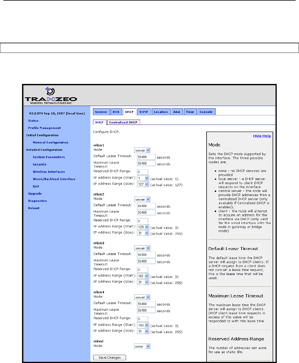
Chapter 9: Client Addressing Schemes
TR0153 Rev. E1 70
The actual start address and size of a segment are accessible via the ‘ip.implicit.start.actual’
and ‘ip.implicit.size.actual’ parameters. These may values may differ from the requested
values if the rules for setting these parameters were not abided by.
Web GUI
The address space segments’ start addresses and sizes can be set via the web interface using
the “DHCP” sub-tab on the “DHCP” tab on the “System Parameters” page (see Figure 38).
Figure 38. Address space settings when using the implicit addressing scheme
Chapter 9: Client Addressing Schemes
TR0153 Rev. E1 71
9.2 Explicit Addressing Scheme
When using explicit addressing scheme, the IP parameters for each interface must be
specified manually on the “Wireless Interface” and “Wired/Backhaul Interface” pages.
When specifying the IP addresses and subnet sizes for the client access interfaces, the
following rules should be followed:
• Specify IP address and subnet combinations that do not lead to misalignment, e.g.
10.0.0.4/24 is not a properly aligned address/subnet size combination.
• Do not specify subnets that are in the following ranges:
o 169.254.0.0/16
o 127.0.0.0/8
o The class B network used by the mesh (typically 172.29.0.0/16)
• Each subnet specified for a client access interface must not overlap with that of any
other client access interface in the mesh neighborhood.
• Do not specify any subnets for client access interfaces that overlap with subnets outside
the mesh neighborhood that you want mesh clients to be able to connect to.
Do not specify a gateway IP address for any of the client access interfaces
when operating using the explicit addressing scheme. This field should be left
blank for each interface.
CLI
Set the ‘implicit.enable’ parameter in the ‘mesh0’ interface to ‘no’ to select the explicit
addressing scheme. The example below demonstrates this.
> use mesh0
sys> set implicit.enable=no
See sections 11.1.2 and 12.4 for instructions on how to set the IP addresses for the wired and
wireless client access interfaces when using the explicit addressing scheme.
Web GUI
The addressing scheme is set with the “Implicit Addressing” drop-down menu on the “System”
tab of the “System” page (see Figure 36). Set this to “disabled” to use the explicit addressing
scheme.
See sections 11.1.2 and 12.4 for instructions on how to set the IP addresses for the wired and
wireless client access interfaces when using the explicit addressing scheme.
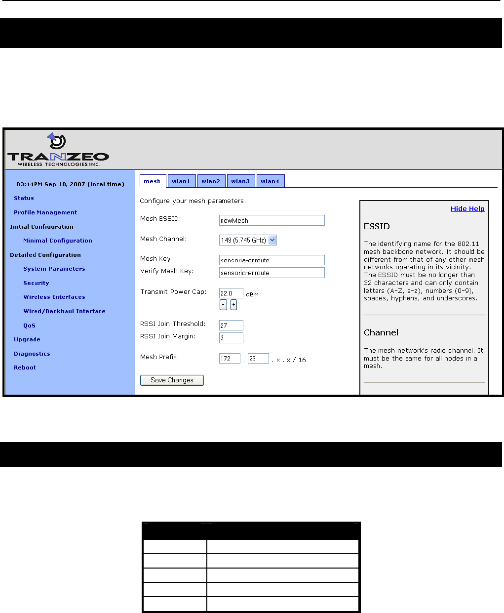
Chapter 10: Mesh Radio Configuration
TR0153 Rev. E1 72
10 Mesh Radio Configuration
The EnRoute500 has an 802.11a radio dedicated to mesh backhaul traffic. The settings for this
radio are independent of any settings for the radio used for the EnRoute500’s built-in virtual
access points. The channel, SSID< and encryption settings for the mesh radio must be the
same on all EnRoute500s in a given mesh neighborhood for them to be able to communicate.
Figure 39. Mesh interface parameters
10.1 Channel
The 802.11a radio can be set to operate in the channels listed in Table 9. All these channels
are non-overlapping.
Channel Center Frequency (GHz)
149 5.745
153 5.765
157 5.785
161 5.805
165 5.825
Table 9. Mesh radio channels and frequencies

Chapter 10: Mesh Radio Configuration
TR0153 Rev. E1 73
All the devices in a mesh neighborhood need to be configured to use the same 802.11a
channel.
CLI
The mesh radio channel is set with the ‘channel’ parameter in the ‘mesh0’ interface as shown
in the example below.
> use mesh0
mesh0> set channel=157
Web GUI
The mesh radio channel can be set via the web interface using the “Mesh” tab on the “Wireless
Interfaces” page (see Figure 39).
10.2 Service Set Identifier (SSID)
The Service Set Identifier, or SSID, is used in 802.11 communication to identify a particular
network. It differentiates logical networks that operate on the same radio channel. The mesh
radio SSID for all the devices in a mesh neighborhood must be the same. If you have adjacent
mesh neighborhoods where one or more devices from each neighborhood are within
communication range of each other, the SSID for the neighborhoods must be different if you
wish to preclude mesh communication between these neighborhoods and preventing
repeaters from autonomously deciding which neighborhood to be part of.
The SSID value must be a text string that has a maximum length of 32 characters. It must only
contain alphanumeric characters, spaces, dashes (“-“), and underscores (“_”). The SSID
setting is case sensitive.
CLI
The mesh radio SSID is set as shown in the example below. When setting an ESSID that
contains spaces, the SSID value must be enclosed by quotes. The quotes are optional
otherwise.
> use mesh0
mesh0> set essid=”enroute500_mesh”
Web GUI
The mesh radio SSID can be set via the web interface using the “Mesh” tab on the “Wireless
Interfaces” page (see Figure 39).
Chapter 10: Mesh Radio Configuration
TR0153 Rev. E1 74
10.3 Encryption
The mesh radio link can be protected with an encryption key to prevent unauthorized users
from intercepting or spoofing mesh traffic. Each EnRoute500 in a mesh neighborhood must
have the same mesh radio encryption key.
CLI
To enable encryption, set the ‘key’ parameter in the ‘mesh0’ interface. The examples below
illustrate how to set the encryption key. The ‘key’ parameter can either be specified as a 16-
character ASCII string preceded by “s:” or a 32-character hexadecimal string.
Encryption can be enabled using an ASCII key with
> use mesh0
mesh0> set key=”s:abcdefghijklmnop”
or using a hexadecimal key with
> use mesh0
mesh0> set key=”0123456789abcdef0123456789abcdef”
Encryption can be disabled by specifying a blank value as shown below.
> use mesh0
mesh0> set key=
Web GUI
The mesh radio encryption key can be set via the web interface using the “Mesh” tab on the
“Wireless Interfaces” page (see Figure 39). The same encryption key must be entered in both
the “Mesh Key” and “Verify Mesh Key” text boxes for the new key to be accepted.
Only ASCII keys can be entered using the web interface. Unlike the CLI, an
ASCII key should not be preceded by “s:” when entered via the web GUI.
10.4 Transmit Power Cap
The maximum transmit power cap of the mesh radio is configurable. Increased output power
will improve communication range, but will also extend the interference range of the radios. It
is suggested that the transmit power cap is initially set to the maximum level for an installation
and is then reduced if it is determined that the transmit power far exceeds the level required to
maintain links. It is also recommended that a common transmit power cap value is used for all

Chapter 10: Mesh Radio Configuration
TR0153 Rev. E1 75
devices in a mesh to reduce the likelihood of asymmetric links. The default transmit power is
21 dBm.
If the transmit power is set to a value in excess of what can be supported by
the mesh radio, the actual radio output power will be the highest power
supported by the mesh radio.
CLI
The example below shows how to set the mesh radio’s transmit power cap with the ‘txpower’
parameter in the ‘mesh0’ interface. The txpower parameter is specified in dBm, with a
minimum granularity of 0.5 dBm.
> use mesh0
mesh0> set txpower=20
Web GUI
The mesh radio’s transmit power cap can be set via the web interface using the “Mesh” tab on
the “Wireless Interfaces” page (see Figure 39). The “+” and “-“ buttons can be used to increase
or decrease the power cap setting in 0.5 dBm steps, or a value can be entered in the text box.
10.5 RSSI Threshold Levels
The mesh networking algorithm evaluates link qualities to neighboring mesh devices and only
considers links with a received signal strength indicator (RSSI) value equal to or greater than
the ‘RSSI Join’ value specified to be usable. The ‘RSSI Join’ value is set to 27 by default. This
value reflects the lowest RSSI that will allow the mesh radio to operate reliably at its highest
data rate. It is possible to achieve longer link ranges, at the cost of reduced throughput, by
reducing the ‘RSSI Join’ value.
In combination with the ‘RSSI Join’ value, the ‘RSSI Margin’ value is used to set the RSSI level
at which links are dropped. A link will be considered broken when its RSSI drops below the
‘RSSI Join’ level by the amount specified with ‘RSSI Margin’. For example, with an ‘RSSI Join’
value of 27 and an ‘RSSI Margin’ value of 3, the link will be dropped if the RSSI goes below
24. The ‘RSSI Margin’ protects the links from the fluctuation in link strengths due to fading.
Based on empirical testing of the EnRoute500, a value of 3-5 is recommended for outdoor
deployments of the EnRoute500.
CLI
The example below shows how to set the mesh radio’s RSSI thresholds with the
‘fabric.rssi.join’ and ‘fabric.rssi.margin’ parameters in the ‘mesh0’ interface .

Chapter 10: Mesh Radio Configuration
TR0153 Rev. E1 76
> use mesh0
mesh0> set fabric.rssi.join=27
> use mesh0
mesh0> set fabric.rssi.margin=3
Web GUI
The mesh radio RSSI thresholds can be set via the web interface using the “Mesh” tab on the
“Wireless Interfaces” page (see Figure 39).
10.6 IP Configuration
The IP address, broadcast address, and netmask associated with the mesh radio interface can
be viewed through the CLI and web interfaces. It is not possible to directly set these values
though. To change the mesh interface IP settings, mesh prefix and the node and mesh ID
settings must be changed (see sections 8.3 and 8.5).
CLI
In the CLI, the mesh IP settings can be viewed with
> use mesh0
mesh0> get ip.address
ip.address = 172.29.2.4 [read-only]
mesh0> get ip.broadcast
ip.broadcast = 172.29.255.255 [read-only]
mesh0> get ip.gateway
ip.gateway = [read-only]
mesh0> get ip.netmask
ip.netmask = 255.255.0.0 [read-only]
Web GUI
The mesh radio IP settings are available through the web interface on the “Config Overview”
tab on the “Status’ page under the heading “Wireless FabricTM (mesh)”.
10.7 Neighbor Status
For a mesh device to be considered a neighbor, a minimum SNR threshold must be met. The
minimum SNR required for a link to be established and maintained are set with the ‘RSSI Join’
and ‘RSSI Margin’ parameters (see section 10.5).
See section 6.2.1 for how to access information, including RSSI and SNR, about mesh
neighbors.
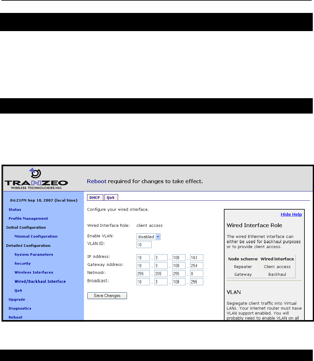
Chapter 11: Ethernet Interface Configuration
TR0153 Rev. E1 77
11 Ethernet Interface Configuration
The function of the Ethernet interface (eth0) depends on the operating scheme that has been
selected (see section 8.2). In repeater mode, the Ethernet interface can be used to connect
client devices to the mesh neighborhood. In gateway mode, the Ethernet interface is used as a
backhaul interface that connects the mesh neighborhood to a WAN. Client devices cannot
connect through the Ethernet interface in this mode.
11.1 IP Configuration for Repeater Devices and Their Clients
When an EnRoute500 is configured as a repeater, client devices can connect to it via the
Ethernet interface to access the mesh network. These client devices can either be assigned
their IP configuration using DHCP, either by a centralized server or a local one on the
EnRoute500, or be manually configured.
Figure 40. Wired interface parameters with EnRoute500 in repeater mode
11.1.1 Ethernet Client Device Address Space
When an EnRoute500 is in repeater mode, the Ethernet interface is either assigned a segment
of the EnRoute500’s class C client address space, if the EnRoute500 is using the implicit
addressing scheme, or an arbitrary address space can be set for the interface when using the
explicit addressing scheme. See section 9 for more information on client addressing schemes.

Chapter 11: Ethernet Interface Configuration
TR0153 Rev. E1 78
11.1.2 Ethernet Interface IP Configuration
The EnRoute500’s Ethernet interface IP configuration can be changed directly when it is in
repeater mode and using the explicit addressing scheme. It should not be changed directly
when the device is in repeater mode and using the implicit addressing scheme.
When an EnRoute500 is configured to use the implicit addressing scheme, set the IP address
to the desired value by modifying the node ID, mesh ID, and LAN prefix parameters (see
sections 8.3 and 9.1.1). Set the netmask by changing the client address space segments as
described in 9.1.2.
When using the explicit addressing scheme, the IP configuration can be set directly. Care must
be taken to avoid using the same or overlapping address spaces on different devices in a
mesh neighborhood.
CLI
You can view the IP settings for the Ethernet interface with the ‘ip.*’ parameters in the ‘eth0’
interface as shown in the example below.
> use eth0
eth0> get ip.*
ip.address = 10.2.4.225 [read-only]
ip.address_force =
ip.broadcast = 10.2.4.255 [read-only]
ip.broadcast_force =
ip.gateway = [read-only]
ip.gateway_force =
ip.netmask = 255.255.255.0 [read-only]
ip.netmask_force =
ip.implicit.size.actual = [read-only]
ip.implicit.size.requested = 31
ip.implicit.start.actual = [read-only]
ip.implicit.start.requested = 225
When an EnRoute500 is in repeater mode and using the implicit addressing scheme, the
Ethernet IP settings can be changed by altering the ‘id.node’, ‘id.mesh’, and ‘id.lanprefix’
parameters in the ‘sys’ interface and the ‘ip.implicit.start.requested’ parameter in the ‘eth0’
interface.
When an EnRoute500 is configured as a repeater, but is using the explicit addressing scheme,
the IP address, netmask, gateway address, and broadcast address can be set using the
‘ip.address_force’, ‘ip.netmask_force’, ‘ip.gateway_force’, and ‘ip.broadcast_force’ parameters
in the ‘eth0’ interface as shown in the example below.
> use eth0
eth0> set ip.address_force= 10.12.7.1
ip.broadcast_force= 10.12.7.255
ip.gateway_force=

Chapter 11: Ethernet Interface Configuration
TR0153 Rev. E1 79
ip.netmask_force=255.255.255.0
Web GUI
The current Ethernet IP settings can be viewed through the web interface on the “Config
Overview” tab on the “Status” page. When using the implicit addressing scheme, the Ethernet
IP settings can be changed by altering the node ID, mesh ID, and LAN prefix settings on the
“System” parameters tab on the “System Parameters” page. When using the explicit
addressing scheme, the IP parameters can be set on the “Wired/Backhaul Interface” page.
11.1.3 IP Configuration of Client Devices via DHCP
When configured as a repeater, the EnRoute500 can be set to serve IP addresses to clients on
the Ethernet interface using DHCP. DHCP-provided addresses can be served either from a
local server on the EnRoute500 or from an external server. The two DHCP modes are
described in detail in section 13.
11.1.4 Manual IP Configuration of Client Devices
The client devices connected via the Ethernet interface that use static IP addresses must have
addresses that are within the subnet of the Ethernet interface.
If the local DHCP server is enabled for the Ethernet interface, IP addresses must be reserved
for statically-configured devices by setting the DHCP reserve parameter. This will reserve the
specified number of IP addresses at the low end of the IP range for the interface. For example,
if the interface has been assigned the IP address 10.2.4.225, the netmask 255.255.255.224,
and the DHCP reserve value 5, the IP addresses 10.2.4.226 through 10.2.4.230 will be
available for use by statically configured devices. The remaining IP addresses in the interfaces
address space can be assigned by the DHCP server to other client devices.
CLI
The number of IP addresses reserved for statically-configured devices connected to the
Ethernet interface is set with the ‘dhcp.reserve’ parameter in the ‘eth0’ interface.
Web GUI
The DHCP reserve value can be set via the web interface using the “DHCP” sub-tab on the
“DHCP” tab on the “System Parameters” page (see Figure 43).
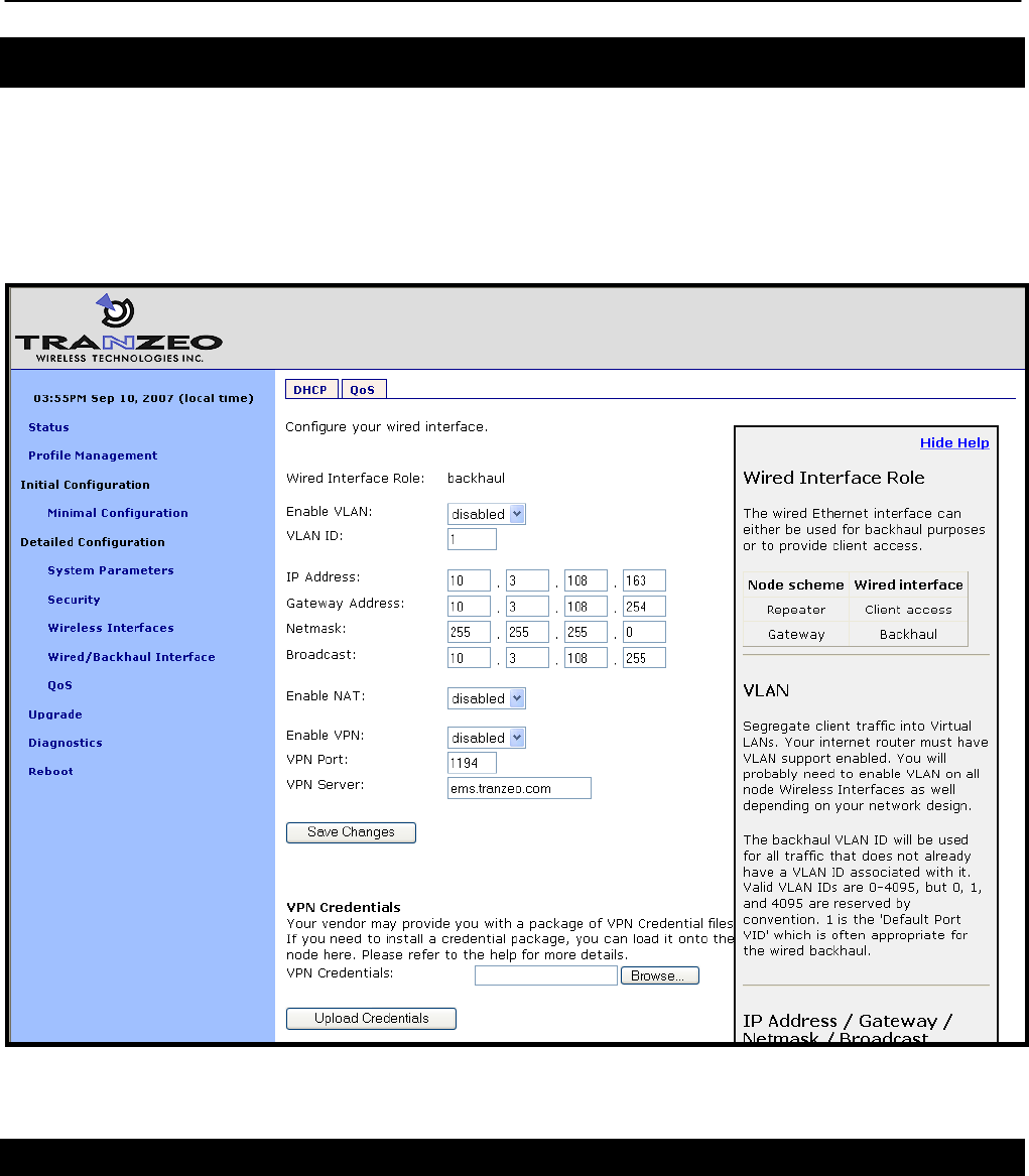
Chapter 11: Ethernet Interface Configuration
TR0153 Rev. E1 80
11.2 IP Configuration for Gateway Devices
When an EnRoute500 is configured as a gateway, the Ethernet interface is used to provide
backhaul capability by connecting it to a WAN or directly to the Internet. Clients cannot connect
to the EnRoute500 through the Ethernet interface when operating in this mode. The Ethernet
interface IP address can either be acquired from a DHCP server on the WAN or be set
manually.
Figure 41. Wired interface parameters with EnRoute500 using wired interface for backhaul
11.2.1 DHCP
When configured as a gateway, the EnRoute500 can be set to obtain an obtain an IP address
for its Ethernet interface using DHCP. To enable the DHCP client mode on the Ethernet
interface, set the Ethernet DHCP mode to ‘client’. When configured as a DHCP client, the
EnRoute500 will continually attempt to contact a DHCP server until it is successful.
Chapter 11: Ethernet Interface Configuration
TR0153 Rev. E1 81
The DHCP reserve parameter (described in section 13.1) has no effect when the
DHCP mode parameter is set to ‘client’.
To disable Ethernet DHCP client mode, set the DHCP mode to ‘none’. If DHCP client mode is
disabled, the IP configuration must be carried out manually, as described in the next section.
CLI
To set the DHCP mode to ‘client’ on the Ethernet interface, set the value of the ‘dhcp.role’
parameter in the ‘eth0’ interface to ‘client’, as shown in the example below.
> use eth0
eth0> set dhcp.role=client
To disable Ethernet DHCP client mode, set the DHCP mode parameter to ‘none’ as shown
below.
> use eth0
eth0> set dhcp.role=none
Web GUI
The Ethernet DHCP mode value can be set via the web interface using the “DHCP” sub-tab on
the “DHCP” tab on the “System Parameters” page (see Figure 43).
11.2.2 Manual IP Configuration
When an EnRoute500 is configured as a gateway, there are no limitations imposed by the
EnRoute500 on the IP address assigned to the Ethernet interface. If the Ethernet DHCP mode
is set to ‘none’, the manually configured IP address will be used. The default IP configuration
that is assigned to the interface based on the node and mesh ID settings is available through
the CLI and the web GUI.
Note that for the manually configured IP address to be used, the Ethernet DHCP mode setting
must be set to ‘none’ if the EnRoute500 is connected to a network which provides access to a
DHCP server.

Chapter 11: Ethernet Interface Configuration
TR0153 Rev. E1 82
The IP configuration settings shown in the ‘eth0’ interface in the CLI and on
the “Wired/Backhaul Interface” page of the web interface do not necessarily
reflect the current settings of the interface. They are the requested settings
and do not take into account whether the interface has been configured via
DHCP. If the Ethernet DHCP mode is set to ‘client’, the ‘ip.address’,
ip.broadcast’, ‘ip.gateway’, and ‘ip.netmask’ parameters will respond to a ‘get’
command with ‘<dhcp>’ to indicate that the parameters will be assigned by a
DHCP server instead of any values assigned via the CLI. Use the ‘ifconfig eth0’
command in the CLI or access the “Status” page in the web interface to get
current interface settings.
CLI
The Ethernet default IP configuration is available through the following read-only parameters:
• ip.address – IP address
• ip.broadcast – IP broadcast address
• ip.gateway – default gateway
• ip.netmask – netmask
These parameters cannot be set though. These default parameters can be overridden with the
parameters listed below.
• ip.address_force
• ip.broadcast_force
• ip.gateway_force
• ip.netmask_force
The example below, shows how a custom IP address can be set for the Ethernet interface
> use eth0
eth0> set dhcp=none
eth0> set ip.address_force=192.168.1.2
eth0> set ip.broadcast_force=192.168.1.255
eth0> set ip.gateway_force=192.168.1.1
eth0> set ip.netmask_force=255.255.255.0
Web GUI
When an EnRoute500 is in gateway mode, the Ethernet IP address, gateway, netmask, and
broadcast address parameters can be set via the web interface using the “Wired/Backhaul
Interface” page (see Figure 41). The current IP values can be viewed on the “Status” page.
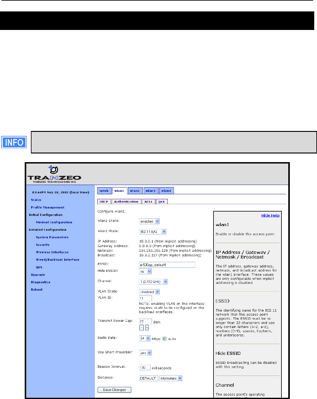
Chapter 12: Virtual Access Point (VAP) Configuration
TR0153 Rev. E1 83
12 Virtual Access Point (VAP) Configuration
The EnRoute500 has an 802.11b/g radio dedicated to access point traffic. The settings for this
radio are independent of any settings for the radio used for the mesh backhaul traffic. The
settings for the four virtual access points supported by this radio can vary from device to
device in the mesh, but typically it is desirable to set certain parameters to the same value for
all the access points in a mesh to allow clients to roam seamlessly within the mesh network.
The EnRoute500’s four virtual access points (VAPs) can be configured to suit different
application needs. These VAPs share a common radio, but, with a few exceptions noted in this
chapter, can be configured independently. The availability of the four VAPs provides more
flexibility in configuration and catering to different user classes than a single AP does.
The interfaces for the VAPs will be referred to as ‘wlanN’ when it applies to any of
the four VAPs. ‘wlan1’ will be used in all examples.
Figure 42. Access point interfaces

Chapter 12: Virtual Access Point (VAP) Configuration
TR0153 Rev. E1 84
12.1 Access Point Interfaces
There are four interfaces that are used to configure the VAPs: wlan1, wlan2, wlan3, and wlan4.
The VAPs have equivalent configuration capabilities and there is no inherent prioritization or
preference for one VAP. The section on quality-of-service settings (section 16) describes how
prioritization on a per-VAP basis can be configured.
12.2 Enabling and Disabling Access Points
Access points can be individually enabled or disabled. A VAP can be configured when it is
disabled and parameter settings are retained when it is disabled.
CLI
A VAP can be enabled with the ‘enable’ parameter in the ‘wlanN’ interface as shown below.
> use wlan1
wlan1> set enable=yes
A VAP can be disabled with the following commands.
> use wlan1
wlan1> set enable=no
Web GUI
Each VAP can be enabled or disabled by setting the “State” parameter via the web interface
using the appropriate “wlanN” tab on the “Wireless Interfaces” page (see Figure 42).
12.3 Virtual Access Point Client Types
The VAPs can be set to support both 802.11b and 802.11g clients, or just 802.11b clients.
CLI
A VAP’s client type mode can be set with the ‘iwpriv.mode’ parameter in the ‘wlanN’ interface
as shown below. See Table 10 for the mapping between valid values for this parameter and
operating modes.
> use wlan1
wlan1> set iwpriv.mode=2

Chapter 12: Virtual Access Point (VAP) Configuration
TR0153 Rev. E1 85
Mode value Mode
2 802.11b
3 802.11b/g
Table 10. VAP mode value/mode mapping
Web GUI
The VAP’s client type mode can be set via the web interface using the appropriate “wlanN” tab
on the “Wireless Interfaces” page (see Figure 42). Two client type options are available:
“802.11b only” and “802.11b/g”.
12.4 Access Point Client Device Address Space
Each VAP interface is either assigned a segment of the EnRoute500’s class C client address
space, if the device is using the implicit addressing scheme, or an arbitrary address space can
be set for the interface when using the explicit addressing scheme. See section 9 for more
information on client addressing schemes.
The EnRoute500 VAPs’ interface IP configurations can be changed directly when it is using
the explicit addressing scheme. They cannot be changed directly when the device is using the
implicit addressing scheme.
When an EnRoute500 is configured to use the implicit addressing scheme, set the IP address
to the desired value by modifying the node ID, mesh ID, and LAN prefix parameters (see
sections 8.3 and 9.1.1). Set the netmask by changing the client address space segments as
described in 9.1.2.
When using the explicit addressing scheme, the IP configuration can be set directly. Care must
be taken to avoid using the same or overlapping address spaces on different devices in a
common mesh.
CLI
You can view the IP settings for the VAP interfaces with the ‘ip.*’ parameters in the appropriate
‘wlanN’ interface as shown in the example below.
> use wlan1
wlan1> get ip.*
ip.address = 10.2.4.1 [read-only]
ip.address_force =
ip.broadcast = 10.2.4.127 [read-only]
ip.broadcast_force =
ip.gateway = [read-only]
ip.gateway_force =
ip.netmask = 255.255.255.0 [read-only]

Chapter 12: Virtual Access Point (VAP) Configuration
TR0153 Rev. E1 86
ip.netmask_force =
ip.implicit.size.actual = [read-only]
ip.implicit.size.requested = 31
ip.implicit.start.actual = [read-only]
ip.implicit.start.requested = 1
When an EnRoute500 is using the implicit addressing scheme, the VAP IP settings can be
changed by altering the ‘id.node’, ‘id.mesh’, and ‘id.lanprefix’ parameters in the ‘sys’ interface
and the ‘ip.implicit.start.requested’ parameter in the appropriate ‘wlanN’ interface.
When an EnRoute500 is using the explicit addressing scheme, the IP address, netmask,
gateway address, and broadcast address can be set using the ‘ip.address_force’,
‘ip.netmask_force’, ‘ip.gateway_force’, and ‘ip.broadcast_force’ parameters in the appropriate
‘wlanN’ interface as shown in the example below.
> use wlan1
wlan1> set ip.address_force=10.12.8.1
wlan1> set ip.broadcast_force=10.12.8.255
wlan1> set ip.gateway_force=
wlan1> set ip.netmask_force=255.255.255.0
Web GUI
The current VAP IP settings can be viewed through the web interface on the “Config Overview”
tab on the “Status” page. When using the implicit addressing scheme, the VAP IP settings can
be changed by altering the node ID, mesh ID, and LAN prefix settings on the “System”
parameters tab on the “System Parameters” page. When using the explicit addressing
scheme, the IP parameters can be set on the appropriate tab on the “Wireless Interface” page.
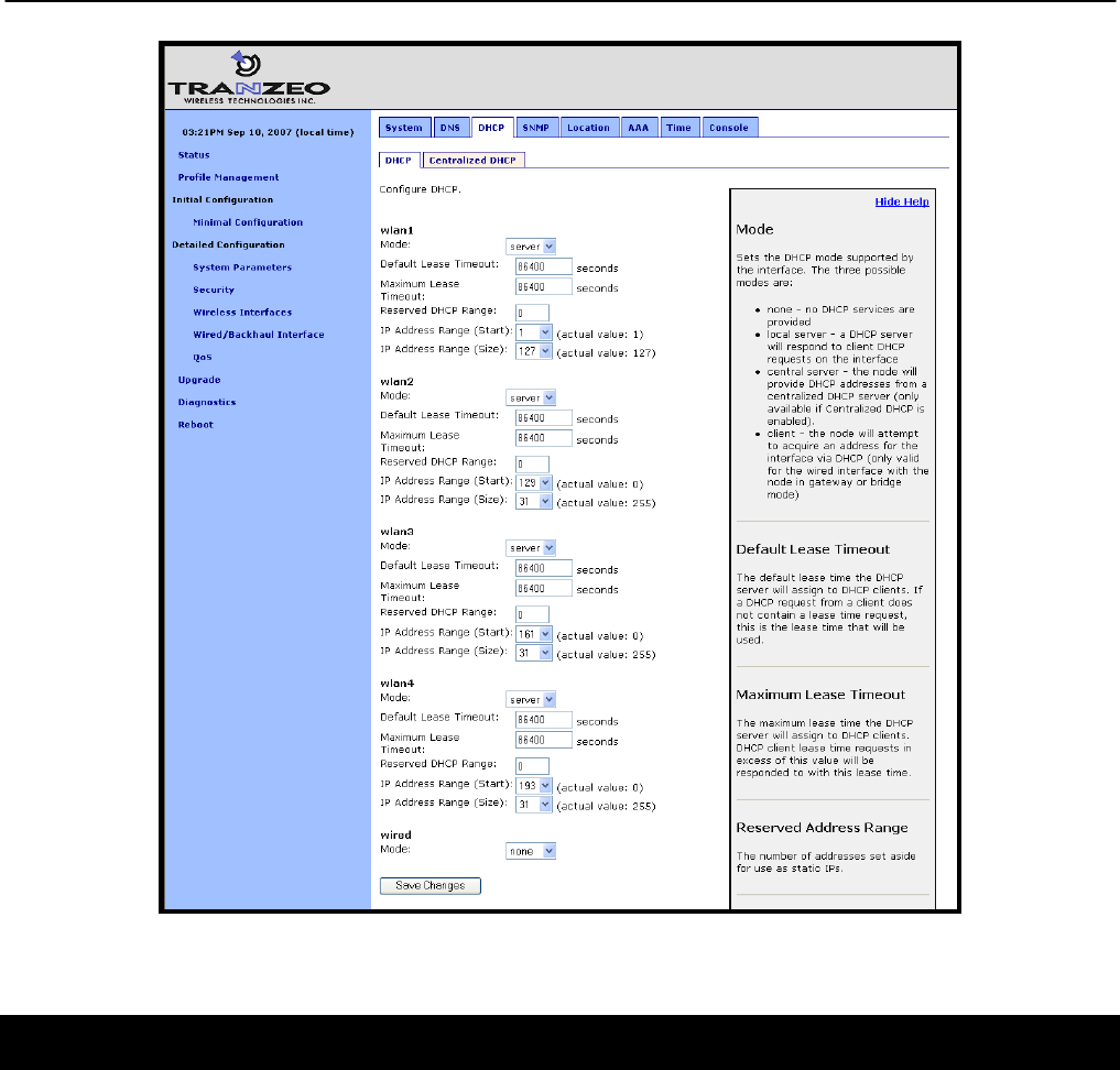
Chapter 12: Virtual Access Point (VAP) Configuration
TR0153 Rev. E1 87
Figure 43. Access point and wired DHCP and address space settings
12.5 Channel
The 802.11b/g radio can be set to operate in the channels listed in Table 11.
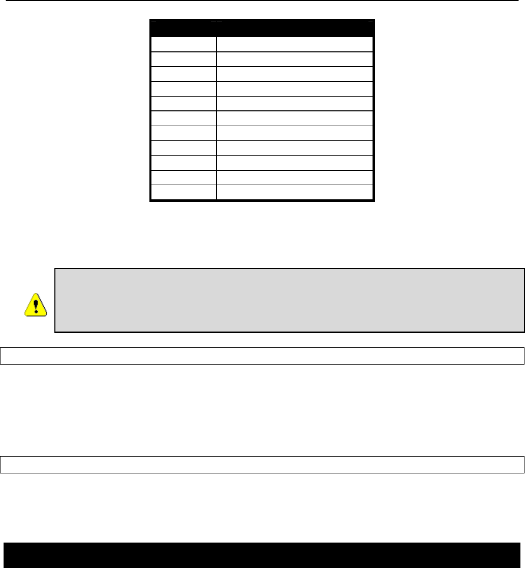
Chapter 12: Virtual Access Point (VAP) Configuration
TR0153 Rev. E1 88
Channel Center Frequency (GHz)
1 2.412
2 2.417
3 2.422
4 2.427
5 2.432
6 2.437
7 2.442
8 2.447
9 2.452
10 2.457
11 2.462
Table 11. Access point channels and associated center frequencies
Note that only channels 1, 6, and 11 are non-overlapping.
It is not possible to configure VAPs to use different channels. If the channel
for wlan2 is changed, the channel will be changed for wlan1, wlan3, and wlan4.
However, different devices in a mesh neighborhood can be set to use different
VAP channels in order to reduce co-channel interference.
CLI
The AP channel is set with the ‘channel’ parameter in the ‘wlanN’ interfaces. The example
below shows how to set the AP channel to 6.
> use wlan1
wlan1> set channel=6
Web GUI
The VAP channel can be set via the web interface using the appropriate “wlanN” tab on the
“Wireless Interfaces” page (see Figure 42).
12.6 ESSID
The ESSID, or Extended Service Set Identifier, is used in 802.11 infrastructure networks to
identify a particular network consisting of one or more Basic Service Sets. It is used to
differentiate logical networks that operate on the same channel.
Chapter 12: Virtual Access Point (VAP) Configuration
TR0153 Rev. E1 89
Each VAP can be configured with a different ESSID. This allows network traffic to be
separated based on ESSID. Assigning unique ESSIDs to the VAPs in a mesh has
the benefit of allowing a user to configure a client device to connect to a specific
device in the mesh. Typically a mesh will be deployed with the VAP ESSIDs having
the same set of values for each EnRoute500 in order to support seamless roaming.
The ESSID value must be a text string that has a maximum length of 32 characters. It must
only contain alphanumeric characters, spaces, dashes (“-“), and underscores (“_”).The ESSID
setting is case sensitive.
It is possible to hide an AP ESSID by restricting it from broadcasting advertisements for that
ESSID. Whether it is appropriate for an AP ESSID to be hidden depends on the application.
CLI
The VAP ESSID is set as shown in the example below. When setting an ESSID that contains
spaces, the ESSID value must be enclosed by quotes – the quotes are optional otherwise.
> use wlan1
wlan1> set essid=”wlan1_ap”
The broadcast of the ESSID can be controlled with the ‘hide_essid’ parameter in the ‘wlanN’
interface. The example below shows how hiding of the ESSID can be enabled.
> use wlan1
wlan1> set hide_essid=yes
Web GUI
The VAP ESSIDs and their broadcast state can be set via the web interface using the
appropriate “wlanN” tab on the “Wireless Interfaces” page (see Figure 42).
12.7 IP Configuration of Client Devices
The VAP interfaces allow client devices to connect to access the mesh network. The client
devices can either be assigned their IP configuration in one of three ways:
• Via DHCP from a centralized server
• Via DHCP from a local server on the mesh device that the client device is connected to
• Be manually configured

Chapter 12: Virtual Access Point (VAP) Configuration
TR0153 Rev. E1 90
12.7.1 IP Configuration of Clients Devices via DHCP
The EnRoute500 can be set to serve IP addresses to clients on the VAP interfaces using
DHCP. DHCP-provided addresses can be served either from a local server on the
EnRoute500 or from an external server. The two DHCP modes are described in detail in
section 13.
12.7.2 Manual IP Configuration of Client Devices
Client devices that use static IP addresses must have an IP address that is within the subnet of
the VAP interface that they connect to.
If the local DHCP server is enabled for a VAP interface, IP addresses must be reserved for
statically configured devices by setting the DHCP reserve parameter. This will reserve the
specified number of IP addresses at the bottom of the IP range for the interface. For example,
if the interface has the IP address 10.2.4.1, the netmask 255.255.255.128, and the DHCP
reserve value 5, the IP addresses 10.2.4.2 through 10.2.4.6 will be available for use by
statically configured devices. The remaining IP addresses in the interface’s address space can
be assigned by the DHCP server to other client devices.
CLI
The number of IP addresses reserved for statically-configured devices connected to the
Ethernet interface is set with the ‘dhcp.reserve’ parameter in the ‘eth0’ interface.
Web GUI
The ‘dhcp.reserve’ value can be set via the web interface using the “DHCP” sub-tab on the
“DHCP” tab on the “System Parameters” page (see Figure 43).
12.8 Client Devices
Each VAP has a status page that displays information about attached client devices and total
throughput through the VAP. The signal strength of each client device, its MAC address, its IP
address, and the time since data was last received from it are listed. The status pages can be
accessed under the ‘Status’ tab on the ‘Status’ page, as shown in Figure 44.
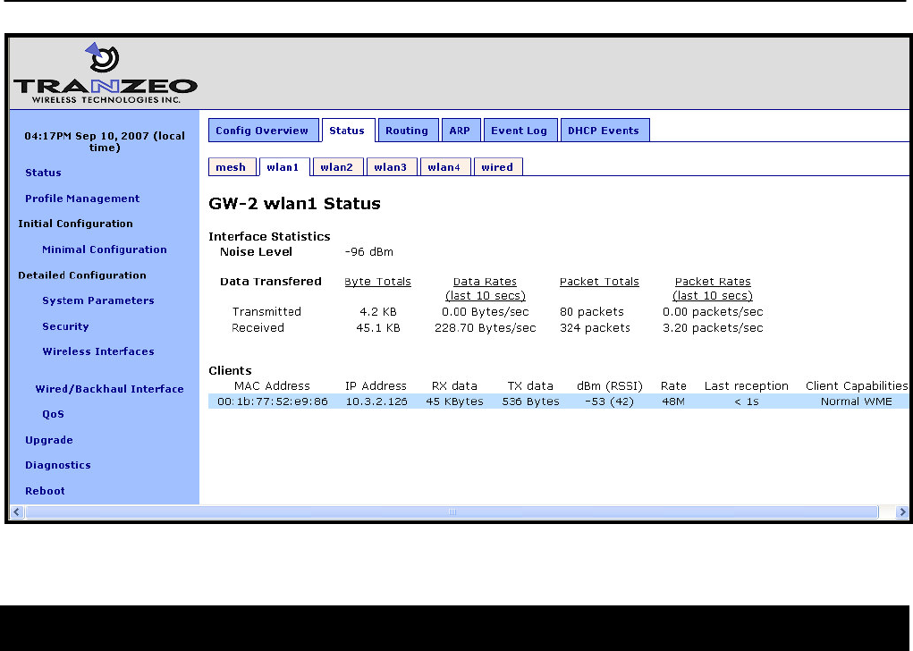
Chapter 12: Virtual Access Point (VAP) Configuration
TR0153 Rev. E1 91
Figure 44. Virtual access point client status information
12.9 Encryption and Authentication
The EnRoute500 supports several common encryption/authentication schemes, including
WEP, WPA, and WPA2, to provide secure wireless access for client devices. WEP keys with
40-bit or 104-bit lengths, pre-shared WPA keys, and multiple WPA-EAP modes.
The WEP and WPA configuration settings for each VAP are independent. An VAP can only
support one of the encryption/authentication modes at a time, but the APs in the EnRoute500
do not all have to use the same encryption/authentication scheme.
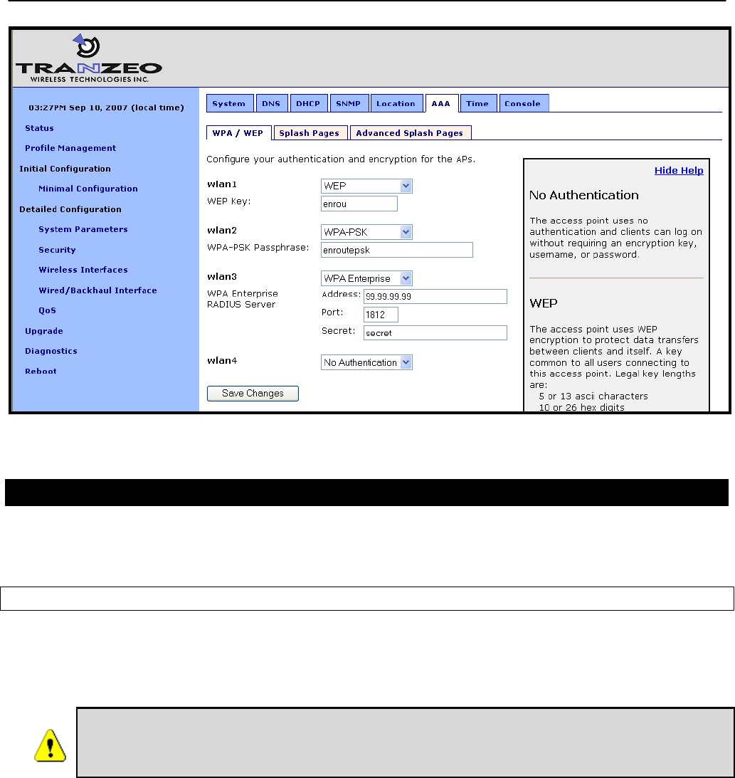
Chapter 12: Virtual Access Point (VAP) Configuration
TR0153 Rev. E1 92
Figure 45. Access point authentication and encryption settings
12.9.1 WEP Encryption
The VAPs can be protected with a WEP-based encryption key to prevent unauthorized users
from intercepting or spoofing traffic.
CLI
To enable WEP-based encryption, set the ‘key’ parameter in the ‘wlanN’ interface. The length
of the encryption key is determined by the format used to specify the ‘key’ value. Valid key
formats and the corresponding encryption type and key length are listed in Table 12.
If WPA is enabled for an interface (‘wpa.enable’ CLI parameter in the ‘wlanN’
interfaces), the WPA settings will be used for encryption and authentication
and the ‘key’ value used to enable WEP will be ignored.

Chapter 12: Virtual Access Point (VAP) Configuration
TR0153 Rev. E1 93
Key format Encryption format Encryption key length
s:<5 ASCII characters>
<10 hex values> WEP 40 bits
s:<13 ASCII characters>
<26 hex values> WEP 104 bits
<blank> None N/A
Table 12. WEP encryption key formats
For example, 104-bit WEP encryption can be enabled using an ASCII key with
> use wlan1
wlan1> set key=”s:abcdefghijklm”
or using a hexadecimal key with
> use wlan1
wlan1> set key=”0123456789abcdef0123456789”
WEP encryption can be disabled by specifying a blank value as shown below.
> use wlan1
wlan1> set key=
Web GUI
WEP encryption can be enabled and the key can be set via the web interface using the
“WPA/WEP” sub-tab under the “AAA” tab on the “System Parameters” page (see Figure 45).
Select “WEP” as the type of encryption from the drop-down menu for the VAP you wish to
configure and set the WEP key in the text box below the drop-down menu. In the example in
Figure 45, ‘wlan1’ has been configured to use WEP.
12.9.2 WPA Pre-Shared Key Mode (WPA-PSK)
In WPA pre-shared key (PSK) mode, a common passphrase is used for client devices
connecting to an EnRoute500 AP. To set the WPA-PSK mode, enable WPA for the interface
and set the pre-shared key value as shown below. The passphrase must be between 8 and 63
characters in length.
The minimum number of characters required for the WPA passphrase is 8. However,
it is recommended that a longer passphrase, with at least 15 characters, is used.
This will increase the strength of the encryption used for the wireless link.

Chapter 12: Virtual Access Point (VAP) Configuration
TR0153 Rev. E1 94
CLI
The example below shows how to enable WPA-PSK mode for wlan1. The ‘wpa.key_mgmt’
parameter must also be set to indicate that PSK mode is being used, as shown below.
> use wlan1
wlan1> set wpa.enable=yes
wlan1> set wpa.key_mgmt=”WPA-PSK”
wlan1> set wpa.passphrase=long_passphrases_improve_encryption_effectiveness
Web GUI
WPA-PSK can be enabled and the pre-shared key can be set via the web interface using the
“WPA/WEP” sub-tab under the “AAA” tab on the “System Parameters” page (see Figure 45).
Select “WPA-PSK” as the type of encryption/authentication from the drop-down menu for the
VAP you wish to configure and enter the WPA-PSK key in the text box below the drop-down
menu. In the example in Figure 45, ‘wlan2’ has been configured to use WPA-PSK.
12.9.3 WPA EAP Mode
In WPA-EAP mode, a client device is authenticated using an 802.1x authentication server,
which is typically a RADIUS server.
The supported EAP modes are:
• TLS (X509v3 server & client certificates)
• PEAP-TLS (X509v3 server & client certificates)
• TTLS (X509v3 server certificate)
• PEAP-MSCHAPv2 (X509v3 server certificate)
The following information must be provided about the RADIUS server:
• address – the IP address of the 802.1x server that will be used for authentication
• port – the port that the authentication server is listening on (UDP port 1812 by default)
• secret – the shared secret for the authentication server. The secret must be a string that is
no longer than 32 characters in length.
See section 19.5 for instructions on how to test the RADIUS configuration and a specific set of
credentials.
CLI
To configure the EnRoute500 to support 802.1x authentication, the following parameters in a
‘wlanN’ interface must be set:

Chapter 12: Virtual Access Point (VAP) Configuration
TR0153 Rev. E1 95
• wpa.enable
• wpa.key_mgmt
• wpa.auth.server.addr
• wpa.auth.server.port
• wpa.auth.server.shared_secret
The ‘wpa.key_mgmt’ parameter must be set to indicate that both PSK and EAP modes can be
supported, as shown in the example below.
The example below shows how to enable WPA EAP mode.
> use wlan1
wlan1> set wpa.enable=yes
wlan1> set wpa.key_mgmt=”WPA-PSK WPA-EAP”
wlan1> set wpa.auth.server.addr=1.2.3.4
wlan1> set wpa.auth.server.port=1812
wlan1> set wpa.auth.shared_secret=enroute500_radius_secret
Web GUI
WPA-EAP can be enabled and the authentication server parameters can be set via the web
interface using the “WPA/WEP” sub-tab under the “AAA” tab on the “System Parameters” page
(see Figure 45). Select “WPA-EAP” as the type of encryption/authentication from the drop-
down menu for the VAP you wish to configure and set the authentication server IP address,
port, and secret in the text boxes below the drop-down menu. In the example in Figure 45,
‘wlan3’ has been configured to use WPA-EAP.
12.10 Transmit Power Cap
The transmit power cap of the AP radio is configurable. Increased output power will improve
communication range, but will also extend the interference range of the radios. The default
power level is 22 dBm.
If the transmit power is set to a value in excess of what can be supported by
the AP radio, the actual radio output power will be the highest power
supported by the AP radio.
When setting the output power for a VAP, consider the output power of the client
devices that will be communicating the VAP. If these devices have output power
levels that are far lower than that of the VAP, an asymmetric link may result. Such a
link exists when the received signal strength at client device is sufficient for a
downlink to the client device to be established, but the received signal level at the
VAP is not sufficient for an uplink from the client device to be established.

Chapter 12: Virtual Access Point (VAP) Configuration
TR0153 Rev. E1 96
CLI
The example below shows how to set the VAP radio’s maximum transmit power using the CLI.
The Tx power is specified in dBm, with a granularity of 0.5 dBm.
> use wlan1
wlan1> set txpower=20
Web GUI
The VAPs’ maximum transmit power can be set via the web interface using the appropriate
“wlanN” tab on the “Wireless Interfaces” page (see Figure 42). The “+” and “-“ buttons can be
used to increase or decrease the power setting in 0.5 dBm steps.
12.11 Radio Rate
The APs can be set to communicate at a specific rate or to automatically select the best rate
available. For most applications, choosing automatic rate selection will be the best choice.
CLI
It is not currently possible to set this through the CLI. Please use the web GUI to set this
parameter.
Web GUI
The VAPs’ communication rate can be set via the web interface using the appropriate “wlanN”
tab on the “Wireless Interfaces” page (see Figure 42). To limit communication to a specific
rate, use the drop-down menu to select the appropriate rate and verify that the “Auto”
checkbox is not selected. To set the device to automatically select the most appropriate rate,
click on the “Auto” checkbox to select it.
12.12 Preamble Length
The APs can be configured to use short preambles when there are no client devices present
that only support long preambles. Alternatively, the device can be forced to always use long
preambles. Using short preambles reduces communication overhead, but may not be
supported by older 802.11 client devices.
The preamble length setting is uniform across all VAPs. Changing it for one
will automatically change it for all others as well.

Chapter 12: Virtual Access Point (VAP) Configuration
TR0153 Rev. E1 97
CLI
The example below shows how to set the preamble type used by a VAP using the CLI. The
preamble type is set with the ‘iwpriv.short_preamble’ parameter in the ‘wlanN’ interfaces. To
enable short preambles, set this parameter to ‘1’. To force use of long preambles, set this
parameter to ‘0’.
> use wlan1
wlan1> set iwpriv.short_preamble=1
Web GUI
The preamble types supported by the VAPs can be set via the web interface using the
appropriate “wlanN” tab on the “Wireless Interfaces” page (see Figure 42). To allow support for
short preambles, set the “Use Short Preamble” drop-down menu to “Yes”. To limit preambles
to long ones, set the drop-down menu to “No”.
12.13 Beacon Interval
The APs’ beacon intervals are configurable. The beacon interval must fall in the range from 20
to 500 ms. The beacon interval is set to 100 ms by default.
CLI
The example below shows how to set the beacon interval for a VAP using the CLI. The beacon
interval is set with the ‘iwpriv.beacon_interval’ parameter in the ‘wlanN’ interfaces and is
specified in milliseconds.
> use wlan1
wlan1> set iwpriv.beacon_interval=100
Web GUI
The beacon interval for an AP can be set via the web interface using the appropriate “wlanN”
tab on the “Wireless Interfaces” page (see Figure 42). Enter a value specified in milliseconds in
the “Beacon Interval” field.
12.14 Maximum Link Distance
The 802.11 standard defines delay values in the communication between devices that affect
the maximum communication distance that can be supported. By default, the communication
distance is limited to approximately 4 km (2.5 mi). The maximum communication distance can
Chapter 12: Virtual Access Point (VAP) Configuration
TR0153 Rev. E1 98
be increased by setting a custom maximum link distance value. This value can be specified in
either metric or imperial units.
The maximum link distance setting is uniform across all VAPs. Changing it for
one will automatically change it for all others as well.
CLI
The example below shows how to set the maximum link distance supported by a VAP using
the CLI. The maximum link distance is set with the ‘distance’ parameter in the ‘wlanN’
interfaces and is specified in either kilometers or miles. The ‘units’ parameter in the ‘sys’
interface determines whether the distance units are entered in kilometers or miles. Set ‘units’
to “metric” for kilometers, and to “imperial” for miles.
Set the ‘distance’ parameter to “DEFAULT” or leave it blank to use the default maximum link
range.
> use sys
sys> set units=”metric”
> use wlan1
wlan1> set distance=10
Web GUI
The maximum link distance supported by an AP can be set via the web interface using the
appropriate “wlanN” tab on the “Wireless Interfaces” page (see Figure 42). Enter a value and
specify whether it is in kilometers of miles using the adjacent drop-down menu.
Set the ‘distance’ parameter to “DEFAULT” or leave it blank to use the default maximum link
range.

Chapter 13: Client IP Configuration
TR0153 Rev. E1 99
13 Client IP Configuration via DHCP
Two configuration options exist for assigning IP addresses to client devices using DHCP:
• Each EnRoute500 hosts a local DHCP server and supplies IP addresses to devices
attaching to any of the client access interfaces
• A centralized DHCP server supplies IP addresses to client devices, with the EnRoute500s
relaying DHCP messages between client devices and the centralized server.
The DHCP modes for client access interfaces in a mesh neighborhood can be set individually
to use a local server, a centralized server, or be disabled. This allows a mesh to contain
devices with client access interfaces supporting a combination of centralized and localized
DHCP.
13.1 Using the Local DHCP Server
The EnRoute500 can be set to serve IP addresses to client devices on enabled VAP interfaces
and the Ethernet interface on repeater devices using DHCP.
The IP addresses provided by the local DHCP server will be in the subnet defined by the LAN
prefix, mesh ID, node ID, and the IP address range start address and size parameters in the
appropriate client access interface. For example, for the ‘wlan1’ interface, the start and end of
the address range are:
Start address = <LAN prefix>.
<Mesh ID>.
<Node ID>.
<wlan1 IP address range start address> + 1
End address = <LAN prefix>.
<Mesh ID>.
<Node ID>.
< wlan1 IP address range start address > -
< wlan1 IP address range size > - 2
The EnRoute500 can be configured to set aside a number of IP addresses for client devices
that will use a static IP address. These IP addresses are taken from the pool that DHCP
assigns IP addresses from. Thus, increasing the number of IP addresses set aside for devices
with static IP addresses will reduce the size of the DHCP address pool. The DHCP reserve
parameter controls the number of IP addresses that will be reserved for static use. By default,
this parameter is set to zero, assigning the maximum possible number of IP addresses to the
DHCP pool. You may reserve the entire range of IP addresses, but the EnRoute500 will use at
least the highest address in the range for DHCP.

Chapter 13: Client IP Configuration
TR0153 Rev. E1 100
If the ‘dhcp.reserve’ value is non-zero, the DHCP range start address will be affected as shown
below
Start address = <LAN prefix>.
<Mesh ID>.
<Node ID>.
<wlan1 IP address range start address> + 1 - < wlan1 DHCP reserve>
CLI
The DHCP mode parameters in the ‘wlanN’ and ‘eth0’ interfaces control DHCP behavior.
When the role is set to ‘server’, the EnRoute500 will respond to DHCP requests received from
client devices connected to the interface.
The examples below show how to set the DHCP server state for the ‘wlan1’ interface.
> use wlan1
wlan1> set dhcp.role=server
wlan1> set dhcp.relay.enable=no
To disable the DHCP server, set the ‘dhcp.role’ parameter to ‘none’
> use wlan1
wlan1> set dhcp.role=none
The example below shows how to set the DHCP reserve parameter
> use wlan1
wlan1> set dhcp.reserve=5
Web GUI
The VAP and wired interface DHCP servers’ state can be set via the web interface using the
“DHCP” sub-tab under the “DHCP” tab on the “System Parameters” page (see Figure 46). All
of the interfaces’ DHCP settings can be configured on this page. Set the “Mode” field to
“Server” to set the DHCP mode for a client access interface to be the local server.
The DHCP reserve setting for all VAPs and the wired interface can be set via the web interface
using the “DHCP” sub-tab under the “DHCP” tab on the “System Parameters” page (see
Figure 46).
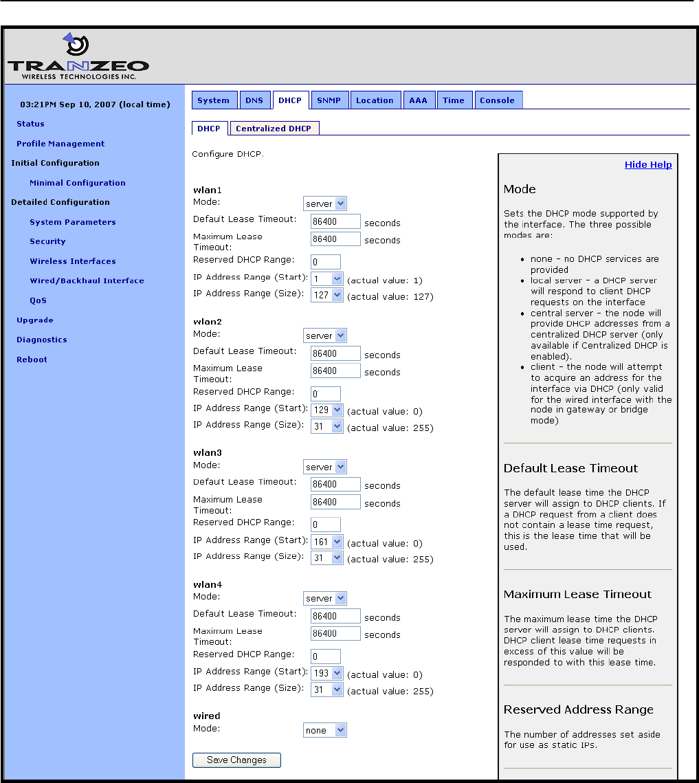
Chapter 13: Client IP Configuration
TR0153 Rev. E1 101
Figure 46. Virtual access point DHCP configuration
Chapter 13: Client IP Configuration
TR0153 Rev. E1 102
13.2 Using a Centralized DHCP Server
Centralized DHCP server mode uses DHCP relaying to enable assignment of IP addresses to
wireless client devices from a common remote DHCP server. The remote DHCP server may
reside either on a host connected to the mesh gateway’s wired segment, or on a server that is
beyond one or more routers. When using a common DHCP server, wireless client devices are
assigned IP addresses from a single address pool, and will roam seamlessly from AP to AP,
assuming sufficiently overlapping AP coverage. In addition, wired clients can also have their IP
addresses assigned by a centralized server.
DHCP relay as a client IP configuration method is needed to facilitate seamless
roaming within a mesh neighborhood. When enabled together with Layer 2
emulation mode, it facilitates delivery of IP traffic regardless of a client’s point of
attachment to the network. It also puts the mesh network into a mode that makes it
behave like a layer 2 distribution and access network expected by most access
controllers. In this mode, subsequently called “layer 2 mesh emulation mode”,
seamless roaming to and from 3rd party bridged access points is also supported.
There are three classes of entities that must be configured when using this DHCP mode:
1. The individual EnRoute500s, including the repeaters and the gateway device
2. The central DHCP server
3. Any intermediate router(s) in the path between the DHCP server and the mesh
neighborhood gateway device
When using a centralized DHCP server, a Client Address Space (CAS) from which client
device IP addresses are assigned must be defined. The active client access interfaces on the
EnRoute500s (there can be up to 5 per EnRoute500) must also have IP addresses that fall
within the CAS. This is to facilitate DHCP relay and selection of client device IP addresses
from the correct DHCP scope on servers that serve hosts connected to different subnets. The
client access interface IP addresses need to be configured statically and must be contiguous.
It is recommended that a contiguous range of IP addresses at either the beginning or the end
of the CAS be set aside, one for each client access interface on the mesh devices.
The Client Address Space (CAS) is not equivalent to the range of addresses
served by the DHCP server. The DHCP-served address range is a subset of the
CAS. The CAS must also include the addresses for the client access interfaces
and the address of the EnRoute1000’s Ethernet interface when the device is
configured as a gateway.
Consider the example where a mesh neighborhood consists of 3 EnRoute500s, including the
gateway device. The DHCP server resides on a host that also acts as the WAN router and is
connected to the mesh gateway’s wired segment. We will set aside 15 IP addresses for the
mesh devices’ client access interfaces (3 devices, up to 5 interfaces per device). Assuming the

Chapter 13: Client IP Configuration
TR0153 Rev. E1 103
client address space is 192.168.5.0/24, with available addresses from 192.168.5.1 to
192.168.5.255, we will use 192.168.5.1 for the server hosting the DHCP server, 192.168.5.2
for the mesh gateway’s backhaul interface, set aside 192.168.5.3 to 192.168.5.18 for the mesh
AP interfaces, and configure the remote DHCP server to serve IP addresses in the range of
192.168.5.19 to 192.168.5.254 to wireless client devices. We will keep 192.168.5.255 as the
broadcast address for the mesh neighborhood.
13.2.1 Support for Clients with Static IP Addresses
When using centralized DHCP server mode for a client access interface, client devices
connected to that interface can be assigned static addresses within the client address space.
However, for these client devices to roam successfully, they must employ duplicate address
detection by sending out ARP requests for their own IP address. Windows-based devices
typically support this requirement. Please contact the client device manufacturer if you are
unsure if your client device meets this requirement.
13.2.2 Configuring the EnRoute500s
When operating in centralized DHCP server mode, each EnRoute500 client access interface
that is to serve DHCP addresses from the centralized server must be explicitly configured to
use centralized DHCP server mode. The EnRoute500s with client access interfaces in
centralized DHCP server mode must also use the same centralized DHCP server. The IP
address of the central DHCP server is set with the DHCP relay server parameter. The server
must be reachable through the mesh neighborhood gateway’s wired backhaul interface.
A gateway router IP address must be entered. This will be supplied to DHCP client devices as
their gateway. This IP address can be the same as for the DHCP server, but need not be.
Each client access interface on the EnRoute500 that is to support centralized DHCP server
mode must have its DHCP mode set to “server” (CLI) or “centralized server” (web GUI) for it to
support relay of IP addresses to client devices from a central DHCP server. This configuration
is set with the DHCP mode parameter for each of the client access interfaces (eth0, wlan1-4).
It is possible to disable DHCP address assignments to client devices on a per-interface basis
and have them use static IP addresses instead. To disable DHCP for an interface, set the
DHCP mode parameter associated with the interface to ‘none’.
The address space that is to be used for the wireless clients is a subnet specified with the
Client Address Space parameter. The value must be specified in CIDR notation (a subnet and
its size separated by a ‘/’), e.g. ‘192.168.5.0/24’
The IP addresses of the client access interfaces (eth0, wlan1-4) need to be manually assigned
to each of the EnRoute500s in the mesh neighborhood. This is done by setting the Address
Base parameter for the interfaces, which is assigned to the first enabled client access

Chapter 13: Client IP Configuration
TR0153 Rev. E1 104
interface. Addresses for the remaining client access interfaces are determined by successively
incrementing the Base Address by 1. It is recommended that the gateway in a mesh
neighborhood be assigned the lowest available value (3 in the example in the CLI section
below) and the repeaters in the mesh neighborhood are given successively higher values, with
an increment of 5 between them (5 is the maximum number of client access interfaces
available on each mesh device, including the Ethernet interface on mesh repeaters).
Layer 2 emulation must also be enabled when operating in centralized DHCP server mode.
This setting is located on the “System” tab of the “System” page of the web interface. See
section 18.2 for more information on layer 2 emulation mode.
CLI
Centralized DHCP server mode is enabled using the ‘dhcp.relay.enable’ and
‘l2.client_mac_fwd’ parameters in the ‘sys’ interface as shown in the example below.
> use sys
sys> set dhcp.relay.enable=yes
sys> set l2.client_mac_fwd=yes
In the example below, the central DHCP server and next WAN router reside on the same
segment to which the mesh gateway’s wired interface is connected.
> use sys
sys> set dhcp.relay.server=192.168.5.2
sys> set dhcp.relay.gateway=192.168.5.1
The example below shows how to set the DHCP mode parameters for the wlan1 and wlan2
interfaces.
> use wlan1
wlan1> set dhcp=server
wlan1> set wlan1.dhcp.relay.enable=yes
> use wlan2
wlan2> set dhcp=server
wlan1> set wlan2.dhcp.relay.enable=yes
To disable distribution of centralized DHCP addresses on an interface, set the interface’s
‘dhcp.role’ parameter to ‘none’ as shown below.
> use wlan3
wlan3> set dhcp=none
The Client Address Space value is set with the ‘dhcp.relay.dhcp_subnet’ parameter in the ‘sys’
interface. This value should be a class A, B, or, C subnet specified using CIDR notation as
shown in the example below.
> use sys
sys> set dhcp.relay.dhcp_subnet=192.168.5.0/24
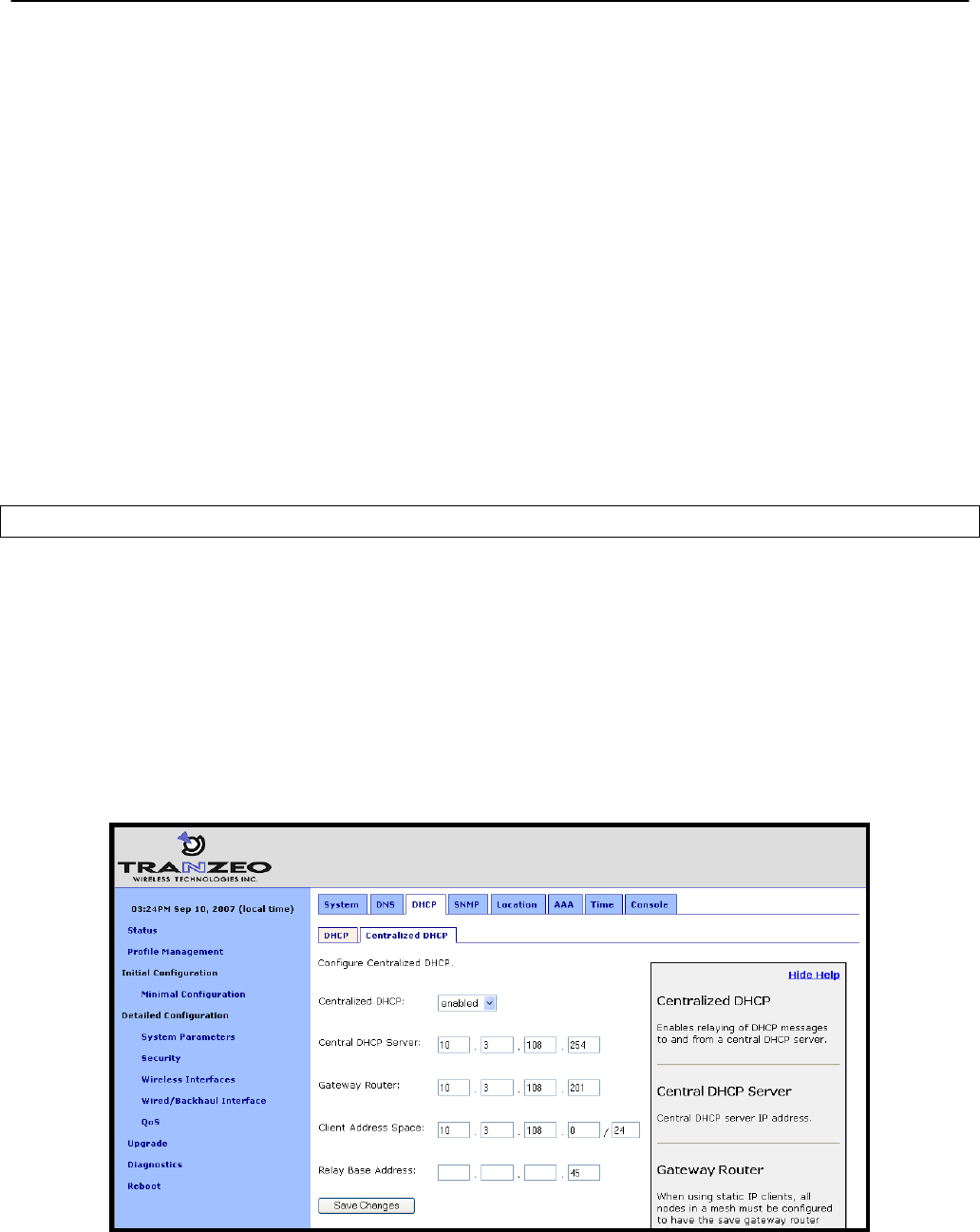
Chapter 13: Client IP Configuration
TR0153 Rev. E1 105
The Base Value, which sets the IP address of client access interfaces on an EnRoute500, is
set through the ‘dhcp.relay.base’ parameter in the ‘sys’ interface. The example below shows
the configuration for a mesh neighborhood consisting of 3 devices.
On the gateway:
> use sys
sys> set dhcp.relay.base=192.168.5.3
on the first repeater device:
> use sys
sys> set dhcp.relay.base=192.168.5.8
and on the second repeater device:
> use sys
sys> set dhcp.relay.base=192.168.5.13
Note that the value of the fourth octet increases by 5 for each device since that is the number
of client access interfaces that each device has, and each interface requires one IP address.
Web GUI
Centralized DHCP server mode can be enabled via the web interface on the “DHCP Relay”
sub-tab under the “DHCP” tab on the “System Parameters” page (see Figure 47). The external
DHCP server IP address, the gateway router address, the Client Address Space parameter,
and the Base Value can also be set on this page. The DHCP mode parameters for all client
access interfaces can be set on the “DHCP” sub-tab under the “DHCP” tab on the “System
Parameters” page. Set the DHCP mode to “central server” for all interfaces whose client
devices should receive addresses from the central DHCP server.
On the “System” tab of the “System” page, set the “L2 Emulation” to “enabled”.
Figure 47. Centralized DHCP server mode settings for use with a centralized DHCP server

Chapter 13: Client IP Configuration
TR0153 Rev. E1 106
13.2.3 Configuring the Central DHCP Server
Guidelines for configuring the central DHCP server are provided below. The full configuration
of the central DHCP server will depend on the type of DHCP server that is used and is beyond
the scope of this document.
Typically the following information must be available in order to configure the server:
1. The local interface (to the DHCP server) over which the DHCP-related messages from
the mesh neighborhood arrive
2. The parameter(s) that define the address lease time
3. Whether DNS and domain names are to be provided by the DHCP server to client
devices
4. The range of the flat IP address that is used for assigning IP addresses to client
devices. The range must not include the IP addresses set aside for the client access
interfaces on each mesh device.
The following is a segment of the dhcpd.conf file for a Linux DHCP server (ISC DHCP server)
that illustrates the scope settings for the mesh network:
subnet 192.168.5.0 netmask 255.255.255.0
{
option broadcast-address 192.168.5.255;
option subnet-mask 255.255.255.0;
option domain-name "domain.com";
range 192.168.5.18 192.168.5.254;
}
Note that in this definition no “routers” option is needed. If a global “routers” option is defined,
the EnRoute500s in a mesh neighborhood will automatically change it to an appropriate value
in DHCP responses to clients based on the centralized DHCP server settings on the
EnRoute500s. In this example, the mesh network includes 3 mesh devices, 2 IP addresses are
set aside for the DHCP server and the mesh gateway, and therefore the address pool starts
from 192.168.5.18.

Chapter 14: Connecting an EnRoute500 Mesh Network to a WAN
TR0153 Rev. E1 107
14 Connecting an EnRoute500 Mesh Network to a WAN
The options for connecting an EnRoute500 gateway to a WAN and establishing layer 3 IP
routing include:
• Static route configuration on the WAN router
• Source network address translation (NAT) on the mesh gateways
• Layer 2 mesh emulation as part of DHCP relay mode.
Table 13 shows compatibility of single vs. multiple mesh gateways with the use of implicit vs.
explicit addressing for the first two configuration options. Note that different options and
requirements exist depending on whether a single or multiple gateways devices are used.
Table 13. Supported WAN connection options for single and multi-gateway
mesh neighborhoods using implicit or explicit client addressing schemes
14.1 Static Routing Configuration on WAN Router
14.1.1 “Single Gateway, Implicit Addressing Scheme” Option
A single EnRoute500 gateway can be directly connected to a WAN without using Network
Address Translation. With this gateway configuration and with the implicit addressing scheme
in use, the router on the network that the gateway is attached to must be configured to forward
the mesh subnet and the LAN subnets to the gateway’s Ethernet interface. The subnets that
need to be forwarded are:
Class B subnet: <LAN prefix>.<Mesh ID>.0.0
Class C subnet: <Mesh prefix >.<Mesh ID>.0
Static Route Configuration on WAN Router NAT on Mesh Gateway
Supported? Requirements Supported? Requirements
Single gateway, implicit
addressing Yes
Define EnRoute500 mesh
gateways as next hop gateway in
WAN router or enable L2
emulation mode on mesh gateway
Yes
Single gateway, explicit
addressing Yes
Define EnRoute500 mesh gateway
as next hop gateway in WAN
router
Yes
Multiple gateways,
implicit addressing Yes Enable L2 mode on all mesh
gateways Yes
Multiple gateways,
explicit addressing No N/A Yes
No client
access
interface can
be in central
DHCP mode

Chapter 14: Connecting an EnRoute500 Mesh Network to a WAN
TR0153 Rev. E1 108
In the case where the LAN prefix is 10 and the mesh prefix is 172.29, the subnets the router
would need to forward to the gateway are 10.2.0.0/255.255.0.0 and 172.29.0.0/255.255.0.0.
Alternatively, to avoid any configuration of the WAN router, enable L2 emulation mode on the
mesh gateway. This will automatically direct traffic destined for the mesh neighborhood’s mesh
devices and clients to the mesh gateway. See section 18.2 for instructions on how to enable
L2 emulation mode.
CLI
The subnet information can be retrieved from the ‘sys’ interface as shown below.
> use sys
sys> get id.*
sys.id.lanprefix = 10
sys.id.mesh = 2
sys.id.meshprefix = 172.29
sys.id.node = 4
Web GUI
The LAN prefix and mesh prefix can be obtained by inspecting the IP addresses available on
the “Status” page. Alternatively, the mesh ID can be obtained from the “Mesh” tab on the
“Wireless Interfaces” page and the LAN prefix can be obtained from the “System” tab on the
“System” page.
14.1.2 “Single Gateway, Explicit Addressing Scheme” Option
A single EnRoute500 gateway can be directly connected to a WAN without using Network
Address Translation. With this gateway configuration and the explicit addressing scheme in
use, the router on the network that the gateway is attached to must be configured to forward
the mesh subnet and all explicitly defined client subnets used in the mesh to the gateway’s
Ethernet interface.
14.1.3 “Multiple Gateway, Implicit Addressing Scheme” Option
Multiple EnRoute500 gateways can be directly connected to a WAN without using Network
Address Translation. With this gateway configuration and the implicit addressing scheme in
use, the router on the network that the gateway is attached to must be configured to use L2
emulation mode on all mesh gateways. This will automatically direct traffic destined for the
mesh neighborhood’s mesh devices and clients to the appropriate mesh gateway, avoiding
any configuration of the WAN router.
See section 18.2 for instructions on how to enable L2 emulation mode.
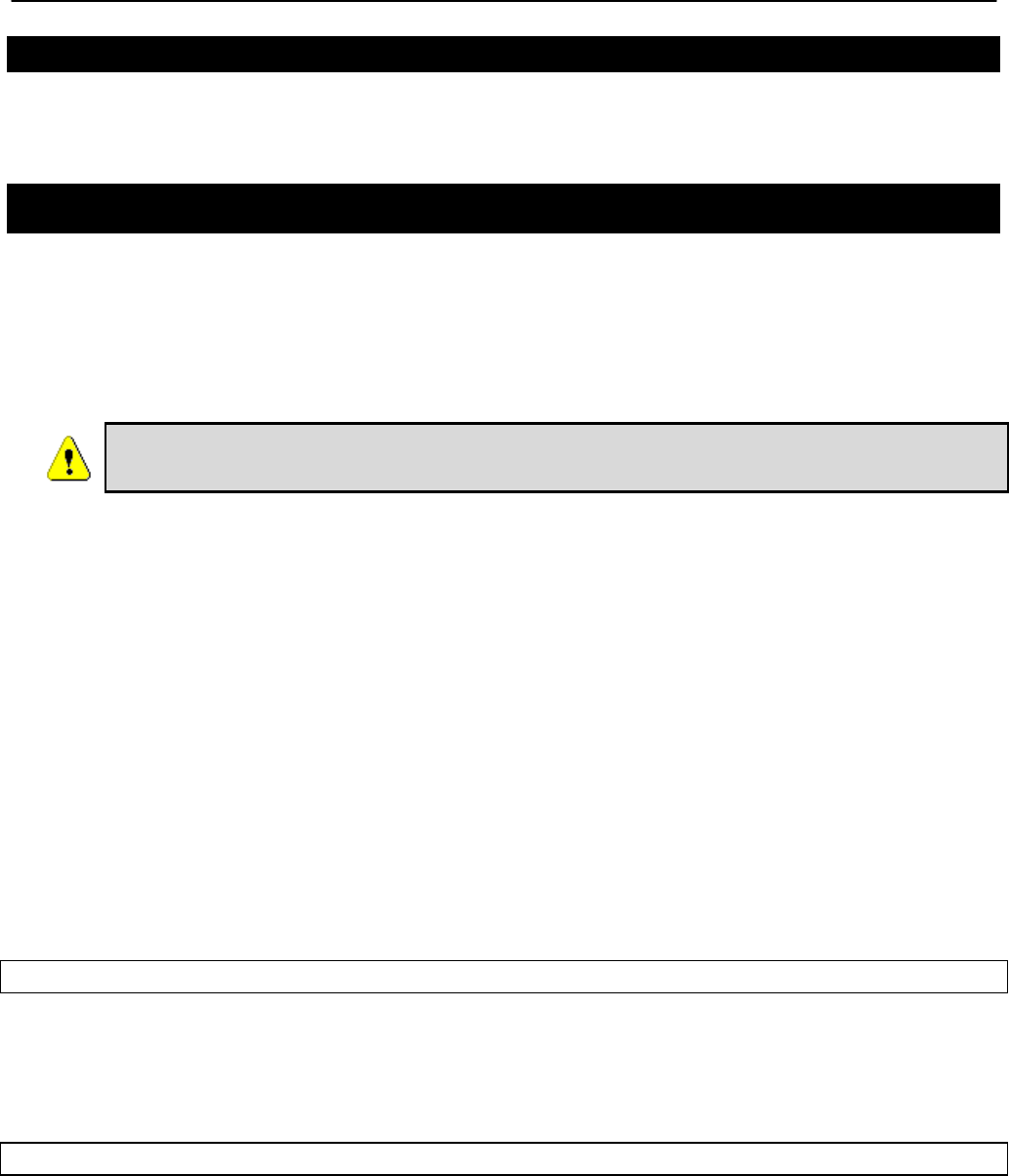
Chapter 14: Connecting an EnRoute500 Mesh Network to a WAN
TR0153 Rev. E1 109
14.1.4 “Multiple Gateway, Explicit Addressing Scheme” Option
This mode of operation is not supported.
14.2 Network Address Translation (NAT) on Mesh Gateways
Network Address Translation (NAT) provides a simple method for connecting a mesh
neighborhood to a WAN router and also prevents hosts that are located on external networks
from initiating connections with client devices and individual mesh repeaters. However, the
mesh devices, as well as their client devices, are able to establish connections and
communicate with hosts connected to networks external to the mesh.
NAT cannot be used if any of the mesh devices in a mesh neighborhood are
using centralized DHCP server mode.
The advantages of using NAT are:
• You can easily attach a mesh neighborhood to an existing network. You do not need to
modify any settings on the WAN router on your existing network to forward IP packets to
client devices within your mesh neighborhood.
• The devices in the mesh neighborhood are shielded from the network that the gateway is
attached to.
• You only consume a single IP address on your existing network when connecting the mesh
neighborhood to it.
The main disadvantages of using NAT is
• You are not able to initiate connections into the EnRoute500s in the mesh neighborhood or
their clients from outside the mesh neighborhood.
• It is not compatible with centralized DHCP server mode.
CLI
To set the NAT state, use the commands
> use sys
sys> set nat.enable=<yes|no>
Web GUI
The NAT state can be set via the web interface on the “Wired/Backhaul Interface” page (Figure
48).
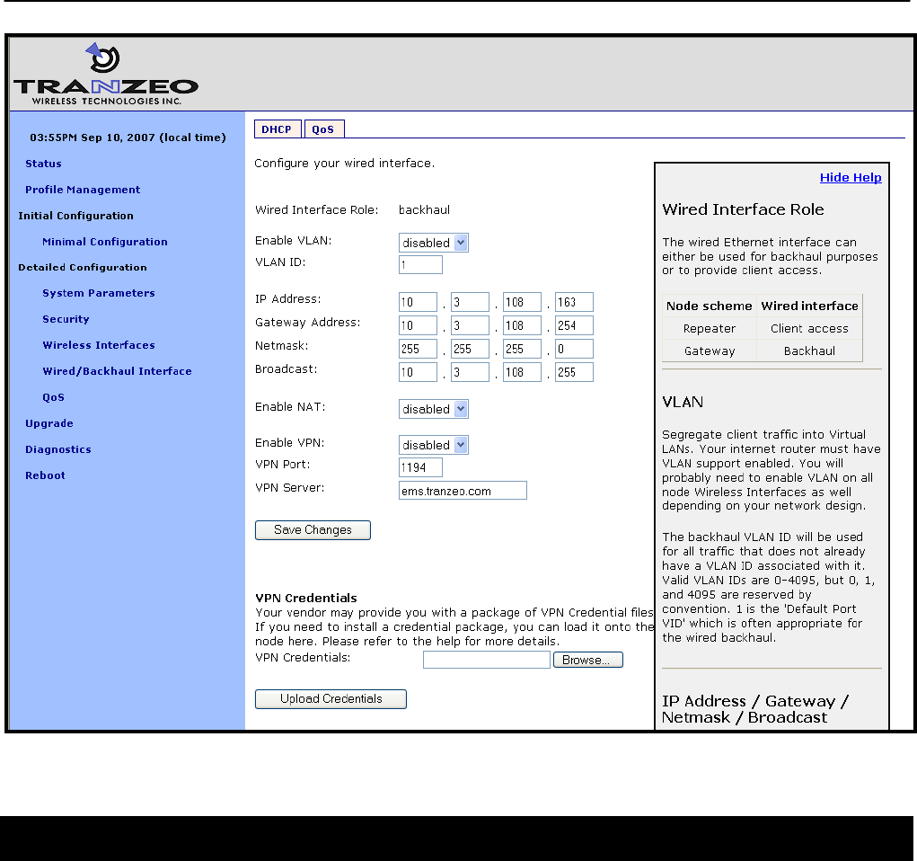
Chapter 14: Connecting an EnRoute500 Mesh Network to a WAN
TR0153 Rev. E1 110
Figure 48. NAT and VPN settings
14.3 Layer 2 Mesh Emulation in DHCP Relay Mode
When DHCP relay and layer 2 emulation mode are both enabled, the mesh network emulates
a layer 2 distribution and access network. In this case the WAN router configuration is limited
to setting up a static route without a designated next-hop gateway via the router’s LAN
interface. In this configuration, additional static routes to the mesh address space as well as
implicit and or explicit address spaces served by the mesh neighborhood may be added,
without the need for specifying a next hop gateway.

Chapter 14: Connecting an EnRoute500 Mesh Network to a WAN
TR0153 Rev. E1 111
14.4 VPN Access to a Mesh Gateway
An EnRoute500 configured as a gateway can establish a VPN connection to an OpenVPN
server. This VPN connection provides the following capabilities:
• Any EnRoute500 in the mesh can be contacted directly from a remote host, even when
NAT is enabled on the gateway device. This allows remote access to devices to monitor
their behavior or reconfigure them
• A secure path between the mesh and a host, which can be used to monitor and reconfigure
the mesh, is established. The control and status traffic passing between the mesh and the
host is protected if it passes over a public network at any point.
The state of the VPN client on the EnRoute500 is set with the Enable VPN parameter. The IP
address of the VPN server and its port are specified with the VPN Server and VPN Port
parameters. Note that the VPN server parameter can either be an IP address or a resolvable
host name.
To allow a connection to be established to an OpenVPN server, appropriate credentials must
also be uploaded to the EnRoute500. Contact Tranzeo for information on how to create VPN
credentials.
CLI
The example below shows how to enable the VPN connection (‘vpn.enable’ in the ‘sys’
interface) and set the server and port parameters (‘vpn.server’ and ‘vpn.port’ in the ‘sys’
interface).
> use eth0
sys> set vpn.enable=yes
sys> set vpn.server=192.168.0.1
sys> set vpn.port=1194
It is not possible to upload VPN credentials with the CLI. Please use the web interface to do
this.
Web GUI
These parameters can be set via the web interface on the “Wired/Backhaul Interface” page
when the device scheme is set to ‘gateway’ as illustrated in Figure 48.

Chapter 15: Controlling Access to the EnRoute500
TR0153 Rev. E1 112
15 Controlling Access to the EnRoute500
The EnRoute500 supports the following features for restricting access to it, restricting inter-
client device communication and access to mesh devices, and shielding client devices from an
external network:
• Firewall
• Client-to-client communication blocking
• Gateway firewall
It further supports controlled network access by client devices through MAC address black lists
and mesh association through MAC white lists.
15.1 Firewall
The EnRoute500 has a firewall that blocks certain types of traffic destined for the EnRoute500.
This prevents client devices attached to an EnRoute500 and devices on the mesh gateway
WAN from connecting to the gateway.
The default firewall rules only affect packets destined for the EnRoute500, and have
no effect on packets forwarded by the device. The firewall should typically be
enabled on all EnRoute500s since it prevents undesired access to the mesh
devices.
By default, the ports listed in Table 14 are set to be allowed for connection to the EnRoute500.
Function Port(s) Type Protocol
SSH 22 Source & destination TCP
DNS 53 Source & destination UDP
DHCP 67, 68 Destination UDP
HTTP 80 Destination TCP
SNMP 161 Source & destination UDP
HTTPS 443 Destination TCP
HTTP redirect (if splash pages are
enabled) 3060 Destination TCP
Roaming support 7202 – 7205,
7207 Destination UDP
OnRamp 20123 Source & destination UDP
Table 14. Source and destination ports allowed by default

Chapter 15: Controlling Access to the EnRoute500
TR0153 Rev. E1 113
CLI
The firewall is enabled by selecting the ‘firewall’ interface and setting the ‘node.enable’
parameter.
> use firewall
firewall> set node.enable=yes
Lists of allowed source and destination ports for inbound TCP and UDP traffic can be
specified. These lists can be set with the following parameters in the ‘firewall’ interface:
• node.tcp.allow.dest
• node.tcp.allow.source
• node.udp.allow.dest
• node.udp.allow.source
The list of allowed ports must be a space-delimited string enclosed by quotes. The example
below shows how to set the TCP source ports parameters.
> use firewall
firewall> set node.tcp.allow.dest=”22 23 80 5280”
Web GUI
It is not possible to configure the state of the firewall and the open firewall ports via the web
interface. It is enabled by default.
15.2 Gateway Firewall
The gateway firewall blocks connections originating outside the mesh neighborhood from
entering the mesh via the gateway, protecting mesh devices and their clients from unwanted
traffic. The gateway firewall will permit return traffic for connections that originate inside the
mesh neighborhood or on mesh clients.
The gateway firewall should only be enabled on EnRoute500s that are configured as
gateways. It is possible to enable the gateway firewall on a repeater device, but it does not
have any effect on the flow of traffic through the device’s Ethernet interface.
If you have enabled NAT (see section 14.2) on the Ethernet interface ‘eth0’, you will
have an implicit firewall that limits the type of inbound connections that are possible.

Chapter 15: Controlling Access to the EnRoute500
TR0153 Rev. E1 114
CLI
The state of the gateway firewall is controlled with the ‘gateway’ parameter in the ‘firewall’
interface. Enable the gateway firewall with
> use firewall
firewall> set gateway=yes
disable it with
> use firewall
firewall> set gateway=no
Web GUI
It is not possible to configure the state of the gateway firewall via the web interface.
15.3 Blocking Client-to-Client Traffic
Client-to-client traffic can be blocked or permitted on a per-interface basis. By enabling client-
to-client traffic blocking for one or more of an EnRoute500’s client access interfaces, the client
devices that attach to that particular interface will not be able to communicate with any client
devices attached to that or any other client access interface in the mesh. Client-to-client traffic
can be controlled for interfaces wlan1, wlan2, wlan3, wlan4, and eth0.
CLI
The parameters that control client-to-client access are all in the ‘firewall’ interface. They are:
• node.allowc2c.eth0
• node.allowc2c.wlan1
• node.allowc2c.wlan2
• node.allowc2c.wlan3
• node.allowc2c.wlan4
To block client-to-client traffic, select the ‘firewall’ interface and set the parameter for the
appropriate interface to ‘no’, To allow traffic between client devices, set the parameter to ‘yes’.
The examples below illustrate how to configure these parameters.
To block client-to-client traffic for client devices attached to wlan1:
> use firewall
firewall> set node.allowc2c.wlan1=no
To allow client-to-client traffic for client devices attached to eth0:
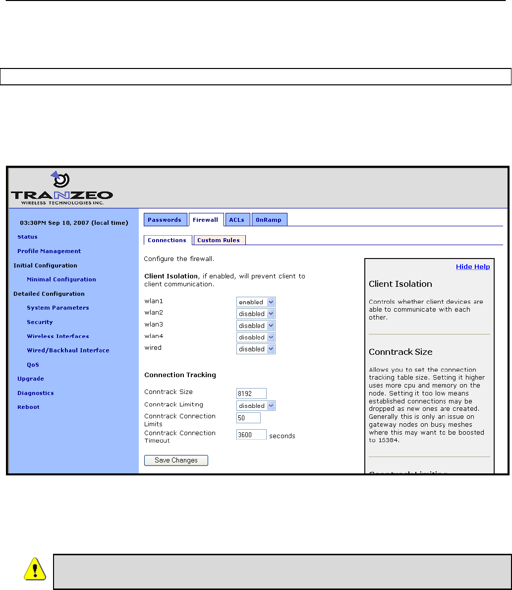
Chapter 15: Controlling Access to the EnRoute500
TR0153 Rev. E1 115
> use firewall
firewall> set node.allowc2c.eth0=yes
Web GUI
The client isolation parameters can be set via the web interface using the “Connections” sub-
tab under the “Firewall” tab on the “Security” page (see Figure 49). By setting an interface’s
client isolation parameter to ‘yes’, client devices connecting to that interface will not be able to
communicate with any other client devices in the mesh.
Figure 49. Connection-related firewall settings
Note that devices connected to different interfaces can only communicate with each other if
client-to-client isolation is disabled for both interfaces.
Client-to-client isolation is only enabled if the EnRoute500 firewall
(firewall.node.enable) is enabled (section 15.1).

Chapter 15: Controlling Access to the EnRoute500
TR0153 Rev. E1 116
15.4 Connection Tracking
The firewall keeps track of existing TCP connections. It is advisable to enable connection
tracking for public networks that can have large numbers of users. In particular, it is important
to enable connection tracking if your network is heavily loaded or if it has users running file
sharing applications. A number of parameters are available for tuning how connection tracking
is handled.
15.4.1 Limiting Number of TCP Connections Per Client Device
The number of TCP connections allowed per client device can be limited. For most use cases,
setting the connection limit to 30 is sufficient.
Users running file sharing applications may have difficulties establishing connections
when TCP connection limiting is enabled since the file sharing application may be
consuming the maximum number of TCP connections allowed.
CLI
The ‘conntrack.connlimit.enable’ parameter in the ‘firewall’ interface is used to set the state of
TCP connection limiting. The ‘conntrack.connlimit.connections’ parameter is used to set the
maximum number of connections allowed per client device.
> use firewall
firewall> set conntrack.connlimit.enable=yes
firewall> set conntrack.connlimit.connections=30
Web GUI
The TCP connection limit-related settings are set on the “Connections” sub-tab on the
“Firewall” tab of the “Security” page (see Figure 49). The “Conntrack Limiting” drop-down box
sets the state of TCP connection limiting and the “Conntrack Connection Limits” sets the
maximum number of TCP connections allowed per client device.
15.4.2 Connection Tracking Table Size
The size of the connection tracking table can be set. This sets maximum aggregate number of
connections that can be supported for all users on all mesh devices in the mesh neighborhood
the gateway is servicing. Allowed values are in the range from 4096 to 16384. A larger
connection tracking table allows more connections to be maintained without dropping older
connections. Typically, the default size of 8192 is adequate for normal operation and the
setting should only be increased on gateway devices with high levels of traffic since they need

Chapter 15: Controlling Access to the EnRoute500
TR0153 Rev. E1 117
to track the connections for all client devices connected to any of the mesh devices in the
gateway’s mesh neighborhood.
CLI
The connection tracking table size is set by selecting the ‘firewall’ interface and setting the
‘conntrack.table_size’ parameter.
> use firewall
firewall> set conntrack.table_size=16384
Web GUI
The connection tracking table size is set with the “Conntrack Size” field on the “Connections”
sub-tab on the “Firewall” tab of the “Security” page (see Figure 49). This field is located under
the “Connection Tracking” heading.
15.4.3 Connection Tracking Timeout
The connection tracking timeout parameter allows you to flush connections that have been idle
for an extended period of time from the connection tracking table. This will help limit the
maximum required size of the connection tracking table. By default, this parameter is set to
3600 seconds (1 hour).
CLI
The connection tracking timeout is set by selecting the ‘firewall’ interface and setting the
‘conntrack.tcp_timeout_established’ parameter. The timeout is specified in seconds.
> use firewall
firewall> set conntrack.tcp_timeout_established=3600
Web GUI
The connection tracking timeout is set with the “Conntrack Connection Timeout” field on the
“Connections” sub-tab on the “Firewall” tab of the “Security” page (see Figure 49). This field is
located under the “Connection Tracking” heading. Specify the timeout limit in seconds.
15.5 Custom Firewall Rules
Custom firewall rules can be added that control how traffic forwarded by an EnRoute500 is
handled. For example, rules can be added to:

Chapter 15: Controlling Access to the EnRoute500
TR0153 Rev. E1 118
• Block client traffic on certain ports
• Block traffic from a given client access interface to a certain subnet
The custom firewall rules can be added on the “Custom Rules” sub-tab on the “Firewall” tab on
the “Security” page as shown in Figure 50. These rules are specified as you would specify
rules for iptables, with the exception of the chain that they are to be added to cannot be
specified. All rules will be applied to the iptables forwarding chain.
List one rule per line in the text box on the “Custom Rules” tab and click on the “Save and
Apply Changes” button when all rules have been entered. The following examples of custom
rules illustrate how to use the custom firewall interface.
Blocking SMTP traffic 25
This rule will block all SMTP traffic, which uses port 25.
-dport 25 -j DROP
Limiting Access Based on Client Access Interface
Packets can be filtered based upon which interface they were received through. For example,
wlan1 and wlan2 can be used to provide users with access to two different, private subnets,
while wlan3 users have access to neither of these subnets. Users of all wlans would have
access to the Internet though. The following rules will:
• Drop traffic from wlan1 destined for the 192.168.2.0 subnet
• Drop traffic from wlan2 destined for the 192.168.1.0 subnet
• Drop traffic from wlan3 destined for the 192.168.1.0 and 192.168.2.0 subnets
-i wlan1 --dst 192.168.2.0/24 -j DROP
-i wlan2 --dst 192.168.1.0/24 -j DROP
-i wlan3 --dst 192.168.1.0/24 -j DROP
-i wlan3 --dst 192.168.2.0/24 -j DROP
Chapter 15: Controlling Access to the EnRoute500
TR0153 Rev. E1 119
Figure 50. Custom firewall settings
15.6 Access Control Lists (ACLs)
Access control lists can be created for each of the VAP interfaces and the mesh interface.
15.6.1 Access Point Access Control Lists (ACLs)
The access control lists (ACLs) for the VAP interfaces (wlan1-wlan4) block access to any
device with a MAC address matching those on the list. Individual ACLs can be defined for each
VAP.
Web GUI
The ACLs can be defined via the web interface on the appropriate “wlanN” sub-tab under the
“ACL” tab on the “Security” page as shown in Figure 51. Enter a MAC address and click on the
“Add MAC” button to add the address to the ACL for that VAP. Once an address has been
added, it will appear at the bottom of the page. To delete a MAC address in an ACL, click on
the “Delete MAC” button next to the address.
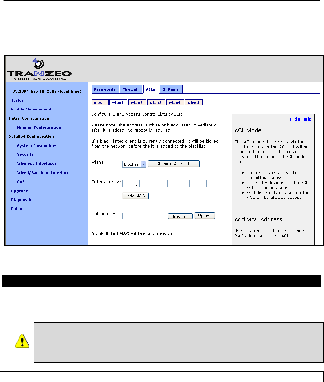
Chapter 15: Controlling Access to the EnRoute500
TR0153 Rev. E1 120
The ACL for a VAP must be enabled after it has been created. Choose “blacklist” from the
drop-down menu and click on “Change ACL Mode” to enable the list. Choose “none” from the
drop-down menu and click on “Change ACL Mode” to disable the ACL.
Figure 51. AP ACL configuration
15.6.2 Mesh ACL
The access control list (ACL) for the mesh interface blocks access to the EnRoute500 via the
mesh interface for any mesh device whose mesh MAC address is not listed in the ACL.
It is possible to isolate a mesh device from other devices in the mesh if the
mesh ACL is incorrectly configured. If the mesh ACL is enabled and no MAC
addresses are present on the list, or the wrong addresses are present, it will
not be possible for other mesh devices to communicate with the device.
Web GUI
The mesh ACL can be defined via the web interface on the “Mesh” sub-tab under the “ACL”
tab on the “Security” page as shown in Figure 52. Enter a MAC address and click on the “Add
MAC” button to add the address to the ACL for that VAP. Once an address has been added, it
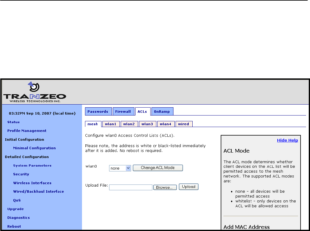
Chapter 15: Controlling Access to the EnRoute500
TR0153 Rev. E1 121
will appear at the bottom of the page. To delete a MAC address in an ACL, click on the “Delete
MAC” button next to the address.
The ACL for a VAP must be enabled after it has been created. Choose “whitelist” from the
drop-down menu and click on “Change ACL Mode” to enable the list. Choose “none” from the
drop-down menu and click on “Change ACL Mode” to disable the use of the ACL for the mesh
interface.
Figure 52. Mesh ACL configuration
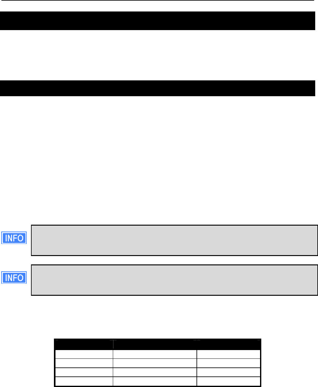
Chapter 16: Quality of Service (QoS) Configuration
TR0153 Rev. E1 122
16 Quality of Service (QoS) Configuration
The EnRoute500 has extensive support for quality of service settings that allow traffic to be
prioritized based on the source interface, destination interface, and type of traffic. The
EnRoute500 QoS scheme allows both rate limiting and rate reservation for all interfaces.
16.1 Priority Levels
The Flow Priority parameters set the relative priority of outbound traffic based on the source
interface. These parameters can be set to an integer value in the range from 0 to 99, with a
higher number indicating a higher priority. If a flow priority level parameter is set to ‘inherit’, the
associated interface will assume the default priority level set. The default flow priority is the
flow priority ‘inherited’ by each interface if another flow priority setting is not applied. The
default flow priority is configurable.
Traffic originating from an interface with a higher priority will take priority over traffic from all
interfaces with a lower priority value until the higher-priority interface has no more data to
send. If multiple interfaces have the same priority level, their traffic will be given equal access
to the outbound interface. Rate reservation and rate limiting, described in the following
sections, can be used to avoid one interface dominating the use of the mesh interface
bandwidth.
As a rule, locally generated traffic should always have the highest priority so that
EnRoute500 control traffic has precedence over client traffic and the mesh can be
maintained.
The absolute values of the flow priority settings do not have any weighting effect. If a
flow priority is higher for one interface than another, the former will always be
prioritized with any remaining bandwidth allocated to the other one.
The Max/Min Hardware Priority parameters can be used to limit the hardware priority queues
that traffic from a particular interface can use for outbound traffic. Valid values for these
parameters are from 1 to 4, which are the priority levels listed in Table 15.
Abbreviation Description Priority level
VO Voice 4 (highest)
VI Video 3
BE Best Effort 2
BK Background 1 (lowest)
Table 15. Hardware flow priority levels

Chapter 16: Quality of Service (QoS) Configuration
TR0153 Rev. E1 123
When sending data out through any of the wireless interfaces (wlanN, mesh0), these hardware
priorities map directly to the 802.11e hardware priority output queues on the wireless card. The
default level for all traffic is Best Effort.
To increase the hardware priority of all traffic originating from a particular interface, set the
value of Min Hardware Priority to a value larger than 1. This will force all traffic from the chosen
interface to use a hardware queue equal to or greater than the Min Hardware Priority value set.
To reduce the maximum hardware priority of traffic from an interface, set the Max Hardware
Priority parameter to a value less than 4. To disable hardware prioritization, set the Min/Max
Hardware Priority parameters to ‘0’.
Setting an interface’s flow priority above that of another interface results in all traffic
originating on the higher flow priority interface blocking traffic on the lower priority
interface until all traffic from the prioritized interface has been sent. In comparison,
elevating the Min Hardware Priority associated with an interface will prioritize, but
not fully block traffic tagged with a lower hardware priority. Instead the medium
access delay will be reduced (as dictated by the IEEE 802.11e standard) for the
traffic with the elevated hardware priority. Thus, these two priority types provide
different gradations of quality control, even when applied en mass to an interface,
although further refinements can be set using the EnRoute500 rate limiting features
discussed below.
Changing hardware priorities does not affect the rate limiting and reservation (section 16.2), it
only affects which output hardware queues that provide the required support for the 802.11e
standard.
CLI
Flow priority levels are set with the ‘in.<intf>.flow_priority’ parameters in the ‘qos’ interface,
where <intf> is one of the following: default, local, eth0, mesh0, wlan1, wlan2, wlan3, wlan4.
‘local’ refers to traffic originating on the device itself, not from its client devices (in practice this
means mesh network control traffic). The example below sets locally generated traffic to have
top priority and wlan1 to have priority over all other interfaces.
> use qos
qos> set in.default.flow_priority=10
qos> set in.local.flow_priority=90
qos> set in.wlan1.flow_priority=20
qos> set in.wlan2.flow_priority=inherit
qos> set in.wlan3.flow_priority=inherit
qos> set in.wlan4.flow_priority=inherit
qos> set in.eth0.flow_priority=inherit
Hardware priority levels are set with ‘in.<intf>.hwpri{max,min}’ in the ‘qos’ interface, where
<intf> is one of the following: default, local, eth0, mesh0, wlan1, wlan2, wlan3, wlan4.
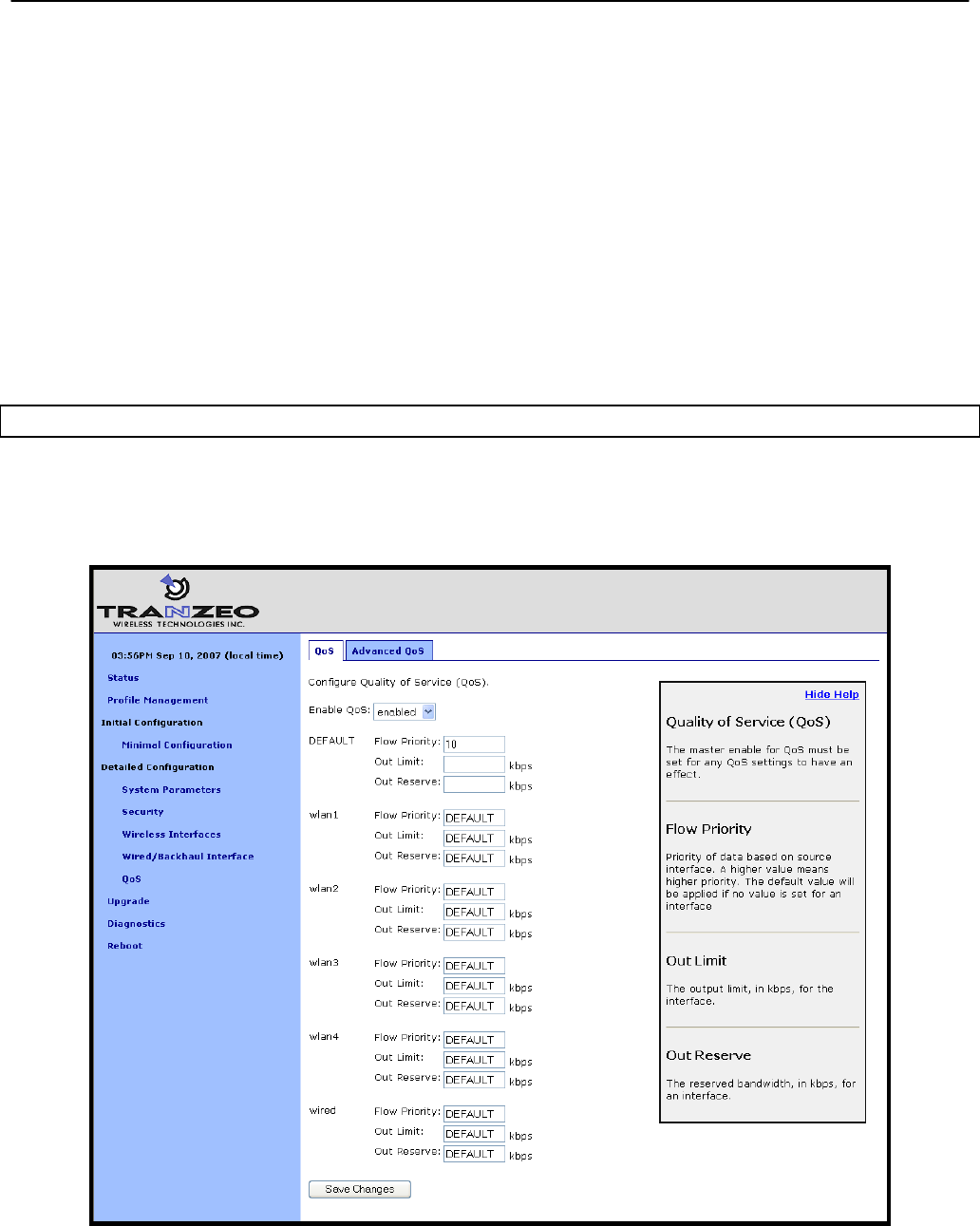
Chapter 16: Quality of Service (QoS) Configuration
TR0153 Rev. E1 124
The example below shows how to configure the system such that all traffic from ‘wlan1’ with a
‘Voice’ or ‘Video’ priority will be reduced to a ‘Best Effort’ priority. Traffic with ‘Best Effort’ and
‘Background’ priorities will not be affected.
> use qos
qos> set in.wlan1.hwpri.max=2
The example below shows how to configure the system such that all traffic from ‘wlan2’ with a
‘Background’ or ‘Best Effort’ priority will be increased to a ‘Video’ priority. Traffic with ‘Video’
and ‘Voice’ priorities will not be affected.
> use qos
qos> set in.wlan2.hwpri.min=2
Web GUI
Flow priorities can be set via the web interface under the “QoS” tab on the “QoS” page (see
Figure 53). The hardware priority levels can be set for each interface under the “Advanced
QoS” tab on the “QoS” page (see Figure 54).
Figure 53. QoS settings
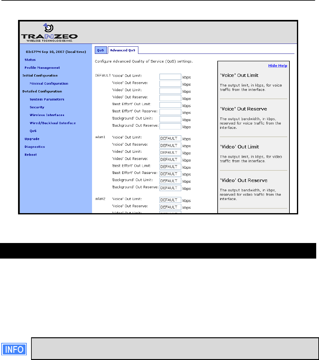
Chapter 16: Quality of Service (QoS) Configuration
TR0153 Rev. E1 125
Figure 54. Advanced QoS configuration (only settings for some interfaces are shown)
16.2 Rate Limiting
A rate limit can be set at each QoS Control Point shown in Figure 55. The Control Points can
be split into three groups, listed below in decreasing order of importance:
• Interface output limit
• Interface output limit of traffic from a particular interface
• Interface output limit of traffic of a certain type from a particular interface
All rate limit parameter values are in kbps. If no rate limit parameter is set, rate
limiting will be disabled for that interface or interface and traffic combination.
The maximum output data rate for interfaces can be limited with the Output Limit parameters
for each client access interface. The default output limit value is applied to interfaces that have
the Output Limit parameter set to ‘inherit’.
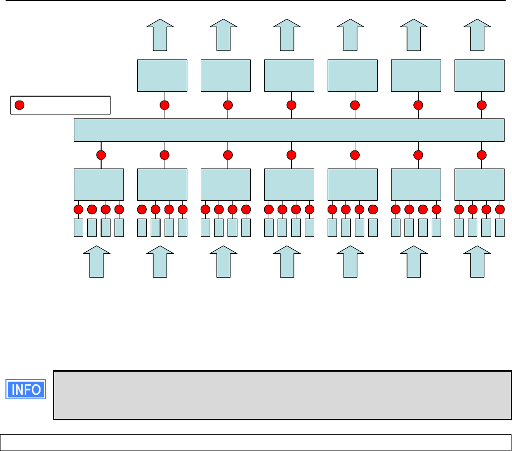
Chapter 16: Quality of Service (QoS) Configuration
TR0153 Rev. E1 126
mesh0local wlan1 wlan2 wlan3 wlan4eth0
mesh0 wlan1 wlan2 wlan3 wlan4eth0
Input
Output
BE
BK
VI
VO
BE
BK
VI
VO
BE
BK
VI
VO
BE
BK
VI
VO
BE
BK
VI
VO
BE
BK
VI
VO
BE
BK
VI
VO
QOS
QoS Control Point
Figure 55. Quality of Service rate limit control points
Data rate limits can also be imposed based on traffic type through an interface. The maximum
data rate for a certain type of traffic that enters the EnRoute500 through a particular interface
and exits it through another interface can be limited.
There is no standalone input rate limiting. Limiting the input rate of an interface on
the EnRoute500 only makes sense in the context of the output for another
interface(s). In most cases you are concerned with mesh0 as the output interface.
CLI
The example below shows how to limit the maximum output rate of the mesh0 interface to 8
Mbps and the maximum output rates of all four wlanN interfaces to 2 Mbps each.
> use qos
qos> set out.mesh0.limit=8192
qos> set out.wlan1.limit=2048
qos> set out.wlan2.limit=2048
qos> set out.wlan3.limit=2048
qos> set out.wlan4.limit=2048
The maximum data rate for traffic that enters the EnRoute500 through a particular interface
and exits it through another interface can be limited with the ‘out.<output intf>.<input intf>.limit’
parameters in the ‘qos’ interface, where <output intf> is one of the following: default, eth0,
mesh0, wlan1, wlan2, wlan3, wlan4; and <input intf> is one of the following: default, eth0, local,

Chapter 16: Quality of Service (QoS) Configuration
TR0153 Rev. E1 127
mesh0, wlan1, wlan2, wlan3, wlan4. The ‘out.default.default.limit’ value is applied to interfaces
that have the ‘out.<output intf>.<input intf>.limit’ parameter set to ‘inherit’ or is left blank.
The example below shows how to limit the maximum output rate of data from wlan1, wlan2,
wlan3, and wlan4 through the mesh0 interface to 2 Mbps, 1 Mbps, 512 kbps, and 256 kbps,
respectively.
> use qos
qos> set out.mesh0.wlan1.limit=2048
qos> set out.mesh0.wlan2.limit=1024
qos> set out.mesh0.wlan3.limit=512
qos> set out.mesh0.wlan4.limit=256
Traffic type limits can be set with the ‘out.<output intf>.<input intf>.<traffic type>.limit.’
parameters in the ‘qos’ interface, where <output intf> is one of the following: default, eth0,
mesh0, wlan1, wlan2, wlan3, wlan4; <input intf> is one of the following: default, eth0, local,
mesh0, wlan1, wlan2, wlan3, wlan4; <traffic type> is one of the following: ‘vo’, ‘vi’, ‘be’, ‘bk’
(see Table 15 for description of traffic types).
The example below shows how to limit the maximum output rate of voice, video, best effort,
and background traffic from wlan1 through the mesh0 interface to 256 kbps, 1 Mbps, 256 kbps,
and 256 kbps, respectively.
> use qos
qos> set out.mesh0.wlan1.vo.limit=256
qos> set out.mesh0.wlan1.vi.limit=1024
qos> set out.mesh0.wlan1.be.limit=256
qos> set out.mesh0.wlan1.bk.limit=256
Web GUI
The interface- and traffic-based Output Limit parameters can be set via the web interface
under the “QoS” and “Advanced QoS” tabs on the “QoS” page (see Figure 53 and Figure 54).
16.3 Rate Reservation
Rate reservation is used to guarantee bandwidth for certain types of traffic. Rate reservations
can be made for traffic based on:
• The traffic input and output interfaces
• The traffic type, input interface, and output interface
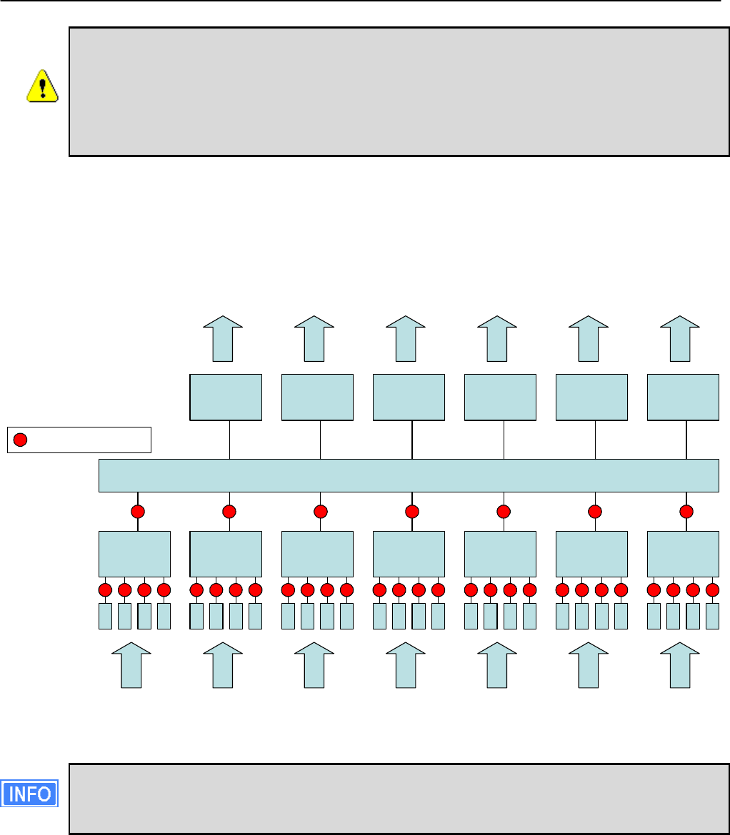
Chapter 16: Quality of Service (QoS) Configuration
TR0153 Rev. E1 128
For rate reservations to be enforced, a rate limit must be set for the traffic type
that the reservation is made for. Setting a rate limit for a broader traffic type, of
which the one the reservation is made for is a subset, is also acceptable. For
example, when making a rate reservation for voice traffic from wlan1 to mesh0
(‘out.mesh0.wlan1.vo.reserve’), a limit must be set with ‘out.mesh0.limit’,
‘out.mesh0.wlan1.limit’, or ‘out.mesh0.wlan1.vo.limit’.
Rate reservations guarantee bandwidth for a particular traffic type, but if no such traffic is
present, the bandwidth reserved will be returned to the pool of available bandwidth for other
traffic types to use. The points at which rate reservations can be made are shown in Figure 56.
These points are similar to where rate limits can be placed, except that rate reservations
require both an input and output interface, whereas rate limits can be made without specifying
an input interface.
mesh0local wlan1 wlan2 wlan3 wlan4eth0
mesh0 wlan1 wlan2 wlan3 wlan4eth0
Input
Output
BE
BK
VI
VO
BE
BK
VI
VO
BE
BK
VI
VO
BE
BK
VI
VO
BE
BK
VI
VO
BE
BK
VI
VO
BE
BK
VI
VO
QOS
QoS Control Point
Figure 56. Quality of Service rate reservation control points
All rate reservation parameter values are in kbps. If no rate reservation parameter is
set, rate reservation will be disabled for that interface or interface and traffic
combination.
A rate reservation, which guarantees a certain amount of bandwidth, can be made for traffic
that enters the EnRoute500 through a particular interface and exits it through another
interface. Rate reservations can also be set based on traffic type through an interface. The

Chapter 16: Quality of Service (QoS) Configuration
TR0153 Rev. E1 129
default value set for the EnRoute500 rate reservation is applied to interfaces that have their
bandwidth reservation parameters set to ‘inherit’ or are left blank.
CLI
The parameters that are used to set these rate reservations are in the ‘qos’ interface and are
of the form ‘out.<output intf>.<input intf>.reserve’, where <output intf> is one of the following:
default, eth0, mesh0, wlan1, wlan2, wlan3, wlan4; and <input intf> is one of the following:
default, eth0, local, mesh0, wlan1, wlan2, wlan3, wlan4.
Typically, most rate reservations will involve reserving bandwidth for traffic from a particular
client access interface to the mesh0 interface. The example below shows how to reserve
differing amount of bandwidth on mesh0 for traffic originating from the wlan1, wlan2, wlan3,
and wlan4 interfaces.
> use qos
qos> set out.mesh0.wlan1.reserve=2048
qos> set out.mesh0.wlan2.limit=1024
qos> set out.mesh0.wlan3.limit=512
qos> set out.mesh0.wlan4.limit=256
A rate reservation for a certain type of traffic that enters the EnRoute500 through a particular
interface and exits it through another interface can be set with the ‘out.<output intf>.<input
intf>.<traffic type>.reserve.’ parameters in the ‘qos’ interface, where <output intf> is one of the
following: default, eth0, mesh0, wlan1, wlan2, wlan3, wlan4; <input intf> is one of the following:
default, eth0, local, mesh0, wlan1, wlan2, wlan3, wlan4; <traffic type> is one of the following:
‘vo’, ‘vi’, ‘be’, ‘bk’ (see Table 15 for description of traffic types).
The ‘out.default.default.limit’ value is applied to interfaces that have the ‘out.<output
intf>.<input intf>.reserve’ parameter set to ‘inherit’ or is left blank.
The example below shows how to reserve bandwidth for voice, video, best effort, and
background traffic from wlan1 through the mesh0 interface to 512 kbps, 1 Mbps, 256 kbps, and
128 kbps, respectively.
> use qos
qos> set out.mesh0.wlan1.vo.reserve=512
qos> set out.mesh0.wlan1.vi.reserve=1024
qos> set out.mesh0.wlan1.be.reserve=256
qos> set out.mesh0.wlan1.bk.reserve=128
Web GUI
The rate reservation parameters can be set via the web interface under the “QoS” and
“Advanced QoS” tabs on the “QoS” page (see Figure 53 and Figure 54).
Chapter 18: Integration with Enterprise Equipment
TR0153 Rev. E1 130
17 Enabling VLAN Tagging
The EnRoute500 supports VLAN tagging, with each client access interface capable of
supporting a different VLAN tag.
17.1 Client Access Interface Configuration
VLAN tagging can be independently controlled on each client access interface (eth0, wlan1-4).
The Enable VLAN parameters for the ‘eth0’, ‘wlan1’, ‘wlan2’, ‘wlan3’, and ‘wlan4’ interfaces
controls the state of VLAN tagging.
VLAN tagging must be enabled on the backhaul Ethernet interface on a mesh
neighborhood’s gateway for VLAN tags to be included in data frames sent to
the WAN. See section 17.2 for more details.
The VLAN ID value for each client access interface is set with the VLAN ID parameter for each
interface. The VLAN ID must be in the range from 0 to 4095. Note that 0 and 4095 are
reserved values and 1 is the default VLAN ID. There are no restrictions on VLAN IDs for
different interfaces or mesh devices having to match or be different.
CLI
The example below shows how to enable VLAN tagging on the ‘wlan1’ interface and set the
VLAN ID to 12 using the parameters ‘vlan.enable’ and ‘vlan.id’ in the ‘wlan1’ interface.
> use wlan1
wlan1> set vlan.enable=yes
> use wlan1
wlan1> set vlan.id=12
Web GUI
The VLAN Enable and VLAN ID parameters can be set via the web interface under the
“wlanN” tabs on the “Wireless Interfaces” page and on the “Wired/Backhaul Interface” page
(see Figure 57).
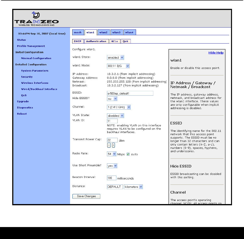
Chapter 18: Integration with Enterprise Equipment
TR0153 Rev. E1 131
Figure 57. Configuring VLAN for VAP interfaces
17.2 Gateway Configuration
For VLAN tags to be preserved on traffic that exits a mesh neighborhood, VLAN support must
be enabled for the Ethernet interface on the mesh neighborhood’s gateway device (the
backhaul interface). The “Enable VLAN” parameter for the Wired/Backhaul interface controls
the state of VLAN tagging. If VLAN tagging is enabled on the gateway’s interface to the WAN,
all outbound traffic will have its VLAN tags preserved. If VLAN tagging is disabled for the
backhaul interface, all VLAN tags will be stripped from frames entering the mesh
neighborhood.
When VLAN is enabled for the backhaul interface, data frames forwarded by the gateway to
the WAN will preserve their existing VLAN tag, if they have one. Frames that do not have a tag
will be tagged with the default VLAN ID for the gateway’s Ethernet interface. The VLAN ID
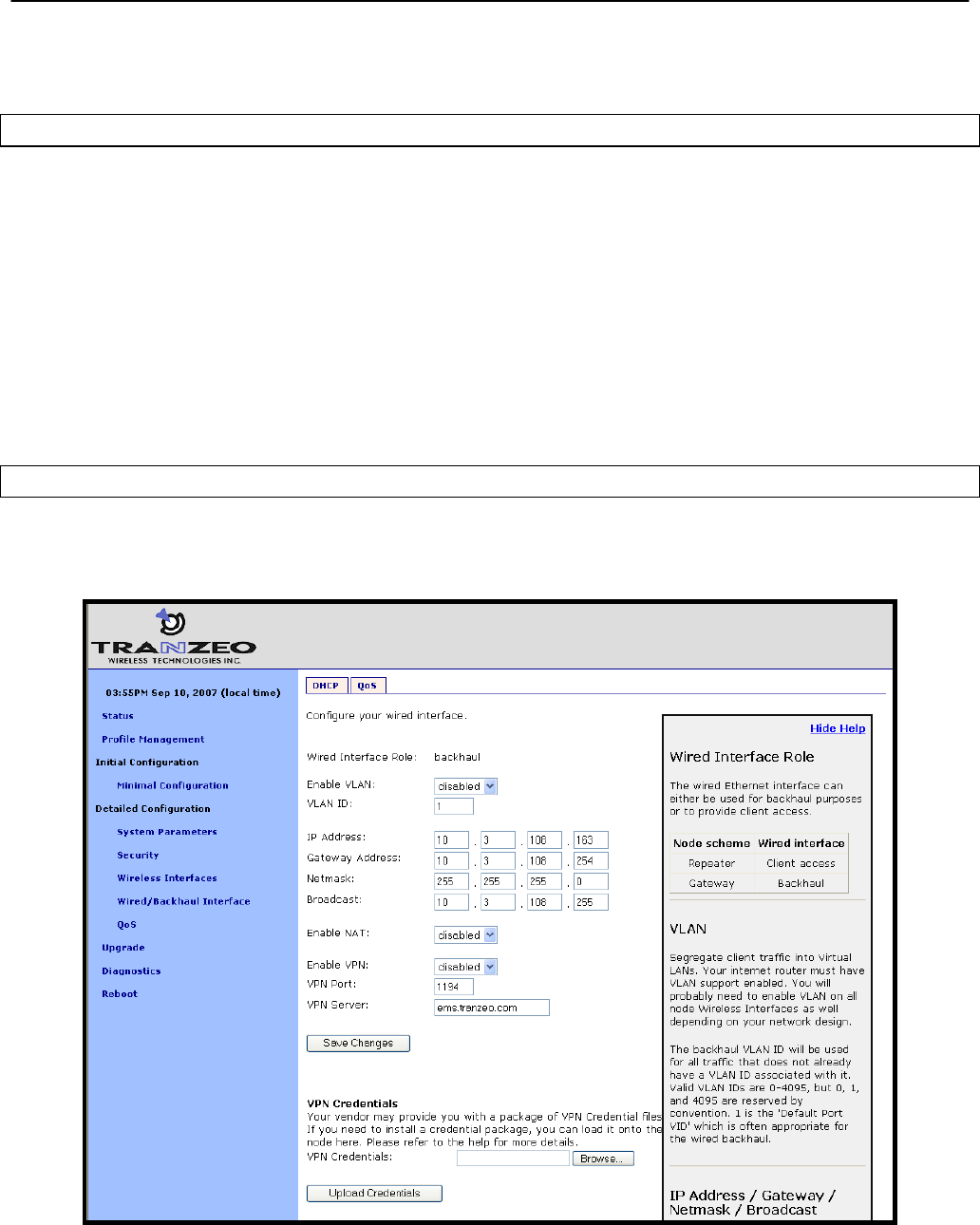
Chapter 18: Integration with Enterprise Equipment
TR0153 Rev. E1 132
must be in the range from 0 to 4095. Note that 0 and 4095 are reserved values and 1 is the
default VLAN ID.
CLI
The example below shows how to enable VLAN tagging on the backhaul interface on a
gateway device using the ‘vlan.enable’ parameter in the ‘eth0’ interface.
> use eth0
eth0> set vlan.enable=yes
The example below shows how to set the VLAN ID for the backhaul Ethernet interface using
the ‘vlan.id’ parameter in the ‘eth0’ interface.
> use eth0
eth0> set vlan.id=1
Web GUI
The backhaul VLAN parameters are set on the “Wired/Backhaul Interface” page as shown in
Figure 58.
Figure 58. Configuring VLAN for backhaul interface

Chapter 18: Integration with Enterprise Equipment
TR0153 Rev. E1 133
18 Integration with Enterprise Equipment
The EnRoute500 supports authentication, accounting, and monitoring services that easily
integrate with enterprise equipment. In this section the following topics are described:
• Splash pages
• Backhaul health monitoring
• Layer 2 client emulation
18.1 Configuring Splash Pages
The EnRoute500 supports splash pages, which can be used to restrict access to the mesh
network and provide information to users that connect to the mesh. When a user connects
through a client access interface to an EnRoute500 with splash page support enabled, the
splash page for the appropriate interface will be displayed and the user will be restricted from
accessing other destinations on the Internet until they have logged in. The splash page can
require the user to enter logon credentials or simply click a button to complete the login
process.
To use splash pages, a number of URLs for login, successful login, and failed login must be
specified. A RADIUS server that provides authentication services may also need to be
specified.
18.1.1 Enabling Splash Pages
The enabling of splash pages can be controlled on a per-interface basis. Two splash page
mode are supported – one which requires client device users to login in to gain access to the
network and another which requires them to simply click on a button on the web page to
proceed.
CLI
Enable or disable splash pages with the ‘splash.enable.wlanN’ parameters in the ‘sys’
interface. For a splash page to be displayed on an interface, the appropriate parameter must
be set to ‘yes’. The example below illustrates how to set the ‘splash.enable.wlan1’ parameter
in the ‘sys’ interface to enable splash pages for the wlan1 interface.
> use sys
sys> set splash.enable.wlan1=yes
Use the ‘splash.auth.server.wlanN.enable’ parameters in the ‘sys’ interface to select whether a
user is required to provide login credentials for a particular interface. The example below
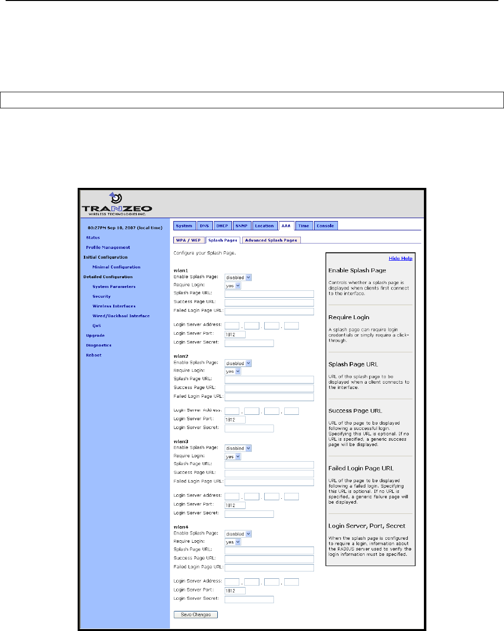
Chapter 18: Integration with Enterprise Equipment
TR0153 Rev. E1 134
illustrates how to set the parameter for the wlan1 interface such that a user will be required to
login to access the network.
> use sys
sys> set splash.auth.server.enable.wlan1=yes
Web GUI
Splash pages can be enabled on a per-interface basis on the “Splash Pages” sub-tab under
the “AAA” tab on the “System Parameters” page of the web interface (see Figure 59). Setting
whether client login is required can also be set on this page with the “Require Login”
parameter.
Figure 59. Splash page configuration

Chapter 18: Integration with Enterprise Equipment
TR0153 Rev. E1 135
18.1.2 Configuring Splash URLs
The URL that a user is redirected to for login purposes can be individually configured for each
client access interface that supports splash pages (wlan1-4). URLs for successful login, failed
login, and error conditions can also be specified for each interface.
The ‘login URL’ parameter sets the URL that a user is redirected to when they attach to the
interface and have not yet been authenticated. This parameter should not be left blank if
splash pages are enabled for the interface. No client would be able to access the network
through the interface if splash pages are enabled and the login URL parameter does not point
to a valid URL.
The ‘success URL’ parameter sets the URL that a user is redirected to when they have
successfully logged in. If this variable is left blank, a default page that indicates login success
will be displayed.
The ‘fail URL’ parameter sets the URL that a user is redirected to when a login attempt fails. If
this variable is left blank, a default page that indicates login failure will be displayed.
The ‘error URL’ parameter sets the URL that a user is redirected to when a login error has
occurred. For example, this page would be displayed if a valid authentication server could not
be reached. If this variable is left blank, a default page that indicates an error has occurred will
be displayed.
CLI
In the examples that follow, <intf> represents any of the client access interfaces ‘wlan1’,
‘wlan2’, ‘wlan3’, or ‘wlan4’. The ‘splash.url.<intf>.login’ parameters in the ‘sys’ interface set the
login URLs. The ‘splash.url.<intf>.success’ parameters in the ‘sys’ interface set the success
URLs. The ‘splash.url.<intf>.fail’ parameters in the ‘sys’ interface set the fail URLs. The
‘splash.url.<intf>.error’ parameters in the ‘sys’ interface set the error URLs
The example below shows how the ‘wlan1’ and ‘wlan2’ interfaces can be set to use different
URLs for the login process.
> use sys
sys> set splash.url.wlan1.login=http://server.domain.com/wlan1_login.htm
sys> set splash.url.wlan1.success=http://server.domain.com/wlan1_success.htm
sys> set splash.url.wlan1.fail=http://server.domain.com/wlan1_fail.htm
sys> set splash.url.wlan1.error=http://server.domain.com/wlan1_error.htm
sys> set splash.url.wlan2.login=http://server.domain.com/wlan2_login.htm
sys> set splash.url.wlan2.success=http://server.domain.com/wlan2_success.htm
sys> set splash.url.wlan2.fail=http://server.domain.com/wlan2_fail.htm
sys> set splash.url.wlan2.error=http://server.domain.com/wlan2_error.htm

Chapter 18: Integration with Enterprise Equipment
TR0153 Rev. E1 136
Web GUI
All of the splash page-related URLs can be set on the “Splash Pages” sub-tab under the “AAA”
tab on the “System Parameters” page of the web interface (see Figure 59).
18.1.3 Sample HTML Code for Splash Pages
The login HTML page must contain specific form information as shown in the sample code in
Figure 60 and Figure 61. Figure 60 contains the code required for an interface that requires a
login. Figure 61 contains code for a login page that the user just clicks through to unlock
network access.
The critical lines in Figure 60 are 6, 12, 15, and 19. The ‘action’ value in line 6 of Figure 60
must point to a server name for which there is a DNS proxy entry on the local mesh device and
the last part of it must be ‘/radius/login.cgi’. The DNS proxy entry, which will be different for
each mesh device in the network, must be mapped to one of the EnRoute500’s IP addresses
(see section 8.8 for more information on how to set the DNS proxy configuration).
The example below shows how to configure the DNS proxy assuming the login page redirects
to the host ‘redirect.domain.com’ and the IP address of the wlan1 interface is 10.1.2.1.
> use sys
sys> set dnsproxy.enable=yes
sys> set dnsproxy.hosts=”dns.proxy.name.here=10.1.2.1”
The DNS proxy setting is used in conjunction with the splash pages to ensure that a
common login URL can be used on all mesh devices. The DNS proxy entry directs
the results of the login process to the right location – that is, the EnRoute500 that the
client device is connected to.
The login page must also contain the ‘input’ fields on lines 12, 15, and 19. These are used to
allow a user logging in to provide their username and password, and to submit them. The
names of these input fields, ‘username’, ‘password’, and ‘login’, must not be changed.

Chapter 18: Integration with Enterprise Equipment
TR0153 Rev. E1 137
1
<html>
2
<head>
3
<title>Test Login Page</title>
4
</head>
5
<body>
6
<form method="POST" action="https://dns.proxy.name.here/radius/login.cgi">
7
Welcoming text or 'Terms of Service' could go here. <br />
8
9
<table border="0">
10
<tr>
11
<td> Username: </td>
12
<td> <input name="username" type="text"><br /> </td>
13
</tr><tr>
14
<td> Password: </td>
15
<td> <input name="password" type="password"> </td>
16
</tr>
17
</table>
18
19
<input name="login" type="submit" value="Submit">
20
</form>
21
</body>
22
</html>
Figure 60. Sample HTML code for login web page with password authentication
If the splash page is not configured to require a user to provide login credentials, the
requirements for the login page are slightly different, as shown in Figure 61. The page must
still contain a form definition similar to that on line 6 in Figure 61. The ‘action’ value must be set
to point to a proxied server name, just as for the case where a user is required to provide login
credentials. The last part of the ‘action’ value must be ‘/splash/nologin.cgi’. Also, a button with
the name ‘login’ must be defined, as shown on line 8 of Figure 61.
1
<html>
2
<head>
3
<title>Test Login Page</title>
4
</head>
5
<body>
6
<form method="POST" action="https://dns.proxy.name.here/splash/nologin.cgi">
7
Welcoming text or 'Terms of Service' could go here.<br />
8
<input name="login" type="submit" value="Continue">
9
</form>
10
</body>
11
</html>
Figure 61. Sample HTML code for web page when authentication is disabled
18.1.4 Configuring the Authentication Server
A RADIUS authentication server must be specified when the splash page is enabled for an
interface and login is required. The following parameters must be specified:
• the server address – can be either a hostname or and IP address

Chapter 18: Integration with Enterprise Equipment
TR0153 Rev. E1 138
• the port on the server that the RADIUS server is listening on
• the shared secret – must be a string of alphanumeric characters that is 32 characters or
less in length.
CLI
The ‘splash.auth.server.<intf>.host’, ‘splash.auth.server.<intf>.port’, and
‘splash.auth.server.<intf>.secret’ parameters in the ‘sys’ interface, where <intf> is either
‘wlan1’, ‘wlan2’, ‘wlan3’, or ‘wlan4’, specify the authentication server to use. The example
below shows how to configure the authentication server for interfaces ‘wlan1’ and ‘wlan2’.
> use sys
sys> set splash.auth.server.wlan1.host=auth1.yourserverhere.com
sys> set splash.auth.server.wlan1.port=1812
sys> set splash.auth.server.wlan1.secret=authsecret
sys> set splash.auth.server.wlan2.host=auth2.yourserverhere.com
sys> set splash.auth.server.wlan2.port=1812
sys> set splash.auth.server.wlan2.secret=authsecret
Web GUI
The authentication server parameters can be set on the “Splash Pages” sub-tab under the
“AAA” tab on the “System Parameters” page of the web interface (see Figure 59) using the
fields for “Login Server Address”, “Login Server Port”, and “Login Server Secret”.
18.1.5 Trusted MAC Addresses
A list of trusted MAC addresses, which do not require splash page authentication, can be
defined. When a device with one of these MAC addresses connects to an EnRoute500, it will
automatically have full access to the WAN.
CLI
The list of trusted MAC addresses is set with the ‘splash.trusted_macs’ parameter in the ‘sys’
interface. The MAC addresses are specified as a list of 48-bit addresses separated by
commas. An example of setting this parameter is shown below.
> use sys
sys> set splash.trusted_macs="aa:bb:cc:00:00:01,aa:bb:cc:00:00:02"
Web GUI
The authentication server parameters can be set on the “Advanced Splash Pages” sub-tab
under the “AAA” tab on the “System Parameters” page of the web interface (see Figure 62).
The list of trusted MAC addresses is displayed on this page. To delete a trusted MAC from the
list, click on the “Delete MAC” button next to the MAC address.
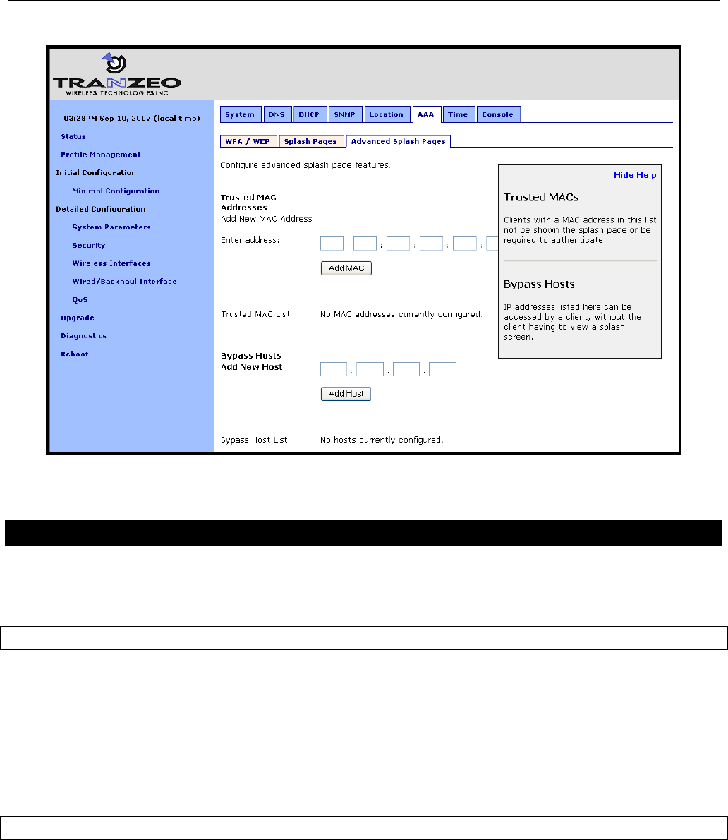
Chapter 18: Integration with Enterprise Equipment
TR0153 Rev. E1 139
Figure 62. Adding trusted MAC addresses and accessible hosts
18.1.6 Bypass Splash Pages for Access to Specific Hosts
It is possible to specify a list of IP addresses that client devices can access without the client
devices having to view a splash screen.
CLI
The list of hosts that can be accessed without having to view a splash screen is set with the
‘splash.bypass_hosts’ parameter in the ‘sys’ interface. The hosts are specified by their IP
addresses and must be separated by commas. An example of setting this parameter is shown
below.
> use sys
sys> set splash.bypass_hosts="1.1.1.1,2.2.2.2"
Web GUI
The IP addresses of hosts that can be accessed without having to view a splash screen can be
set on the “Advanced Splash Pages” sub-tab under the “AAA” tab on the “System Parameters”
page of the web interface (see Figure 62). The list of IP addresses of bypassed hosts is

Chapter 18: Integration with Enterprise Equipment
TR0153 Rev. E1 140
displayed on this page. To delete an IP address from the list, click on the “Delete Host” button
next to the IP address.
18.2 Layer 2 Emulation
Certain back-end systems (e.g. Internet gateways) use the MAC addresses of client devices
for authentication and accounting purposes. The EnRoute500 uses a layer 3 approach to
mesh routing, which means that the client device MAC addresses are typically not provided to
the back-end servers. A layer 2 emulation mode can be enabled on the EnRoute500 to provide
the client device MAC address information to back-end systems. Note that layer 2 emulation
must be enabled to support seamless roaming
When layer 2 emulation is enabled, a mesh neighborhood gateway will send Ethernet (layer 2)
frames to the WAN using the MAC address of the client device the packet originated from as
the source address. Mesh gateways will act as proxies for incoming client traffic, as well as
forward packets with MAC destination addresses of client devices that are in the mesh
neighborhood they service.
In layer 2 emulation mode, a mesh gateway will respond to ARP requests if it has a route to
the target IP address contained in the ARP request. If central DHCP mode is enabled, the
source MAC address will be set to the client device’s MAC address for which a request has
been received, thereby facilitating the emulation of the mesh as a layer 2 network. The list of
subnets for which a mesh gateway has routes includes the mesh and implicit/explicit network
addresses. If central DHCP mode is enabled, the mesh gateway routing table also includes
host routes to addresses in the client address space. Thus care must be taken that these
subnets are not used elsewhere in the network.
In order to reduce the amount of address space consumed by the mesh, the ARP responses
can be limited to a subset of the mesh’s address space. The EnRoute500 can be configured
to:
• Disregard ARP requests for mesh IP addresses (typically in the 172.29.0.0/16 subnet)
• Disregard all ARP requests except for IP addresses within the client address space (if
centralized DHCP server mode is enabled). Note that this is a superset of the previous
case.
CLI
Layer 2 emulation is enabled with the ‘l2.client_mac_fwd’ parameter in the ‘sys’ interface. This
parameter should be set to the same value for all devices in a given mesh neighborhood. The
example below shows how to enable layer 2 emulation.
> use sys
sys> set l2.client_mac_fwd=yes

Chapter 18: Integration with Enterprise Equipment
TR0153 Rev. E1 141
To limit the range of addresses for ARP requests that the gateway will respond to, set the
‘l2.hide_internal.enable’ parameter in the ‘sys’ interface to ‘yes’. Set the
‘l2.hide_internal.gateway.deny.mesh’ in the ‘sys’ interface to ‘yes’ to disregard ARP requests
for IP addresses within the mesh subnet (typically 172.29.0.0/16). Set
‘l2.hide_internal.gateway.deny.all’ in the ‘sys’ interface to ‘yes’ to disregard all ARP requests
(except for addresses within the client address space if centralized DHCP server mode is
enabled).
The example below shows how to disregard all ARP requests except for those for addresses
within the client address space.
> use sys
sys> set l2.hide_internal.enable=yes
sys> set l2.hide_internal.gateway.deny.all=yes
The example below shows how to disregard all ARP except for addresses within the mesh
address space.
> use sys
sys> set l2.hide_internal.enable=yes
sys> set l2.hide_internal.deny.mesh=yes
sys> set l2.hide_internal.deny.all=no
Web GUI
The state of layer 2 emulation is set on the “System” tab of the “System” page (see Figure 63).
The console interface in the web GUI must be used to configure which address ranges the
gateway responds to ARP requests for. See the CLI section above for parameter names and
set these using the console interface (see section 8.15).
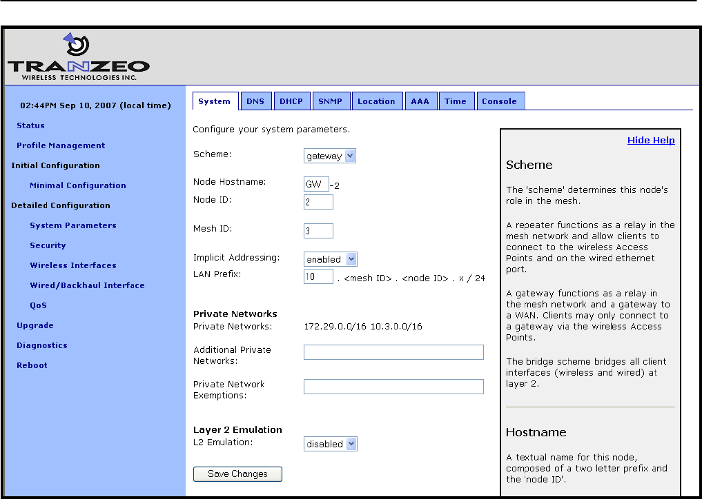
Chapter 18: Integration with Enterprise Equipment
TR0153 Rev. E1 142
Figure 63. Enabling/disabling layer 2 emulation
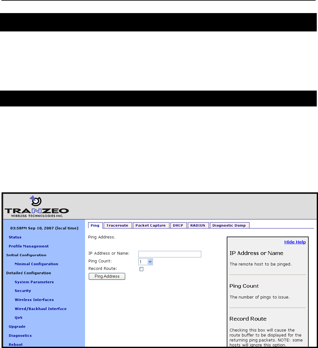
Chapter 19: Diagnostics Tools
TR0153 Rev. E1 143
19 Diagnostics Tools
The EnRoute500 has a number of diagnostics tools to help the user diagnose and correct
configuration issues. These tools are available on the “Diagnostics” page, accessible from the
navigation bar. The individual diagnostics tools are accessible from the row of tabs shown on
the “Diagnostics” page.
19.1 Ping
The “Ping” tab on the “Diagnostics” page allows the user to check for network connectivity by
pinging a remote device (see Figure 64). Either an IP address, e.g. 10.1.2.3, or a hostname,
e.g. www.yahoo.com, can be specified. The number of pings to send can be set to 1, 10, or
100.
Click on “Ping Address” to start pinging the device. The results of the pings will appear on the
bottom half of the page shortly after clicking on the button. There may be a delay of a few
seconds to display the ping results if the ping destination is not responsive.
Figure 64. Pinging a remote device
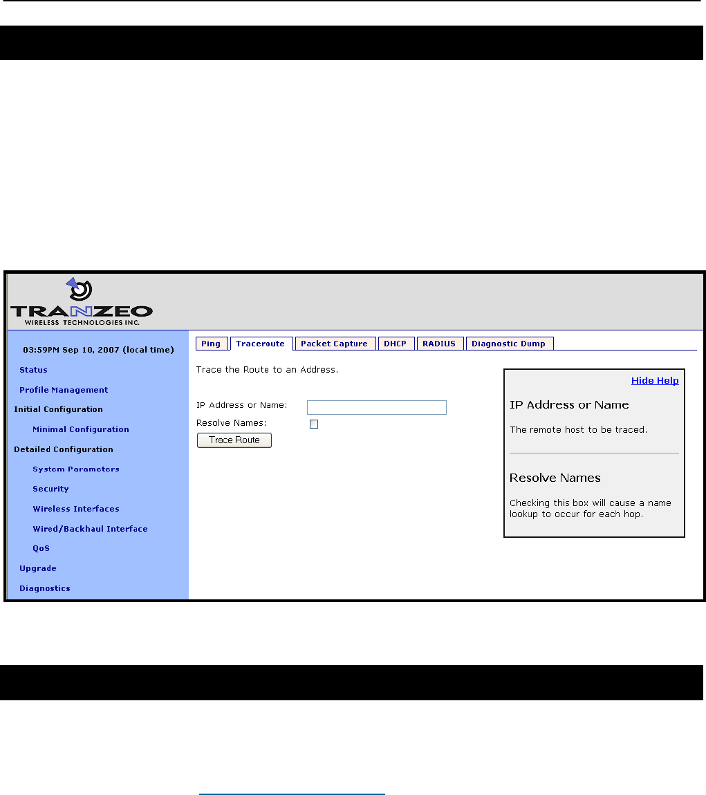
Chapter 19: Diagnostics Tools
TR0153 Rev. E1 144
19.2 Traceroute
The “Traceroute” tab on the “Diagnostics” page allows the user to determine the individual
intermediary devices used to route traffic from the EnRoute500 to a remote device (see Figure
65).
Enter the IP address, e.g. 10.1.2.3, or hostname, e.g. www.yahoo.com, of the device you wish
to find the route path to. Check the “Resolve Names” box if traceroute should show device
names, when available, instead of just IP addresses. Click on the “Trace Route” button to
begin tracing the route. The intermediary nodes will be displayed on the bottom half of the
page. Click on “Stop Trace” to stop the tracing process.
Figure 65. Determining the route from the EnRoute500 to a remote device using traceroute
19.3 Packet Capture
The “Packet Capture” tab on the “Diagnostics” page allows the user to capture traffic on the
EnRoute500’s network interfaces (see Figure 66). The captured data can either be displayed
in the web interface or saved to a file that can be downloaded and analyzed using 3rd-party
tools, such as Wireshark (http://www.wireshark.org/). At most, 10 captured files can be saved
on the EnRoute500 at any given time.
The full array of options available for packet capture is described in Table 16. A number of
examples of common packet capture scenarios are also presented below.

Chapter 19: Diagnostics Tools
TR0153 Rev. E1 145
Capturing DHCP Traffic From Client Device on wlan1
1. Set “Interface” to “wlan1”
2. Set “Protocol” to “all”
3. Set “Packet Count” to “20”
4. Set “Packet length” to 500
5. Click on “DHCP” next to “Common Protocols”
6. Set “Output” to “File”
7. Click on “Start Capture”
8. Allow the capture to complete automatically when the prescribed number of packets has
been captured or click on “Stop Capture” to halt the capture
9. The captured data is accessible by clicking on the link at the bottom of the page under
the heading “Available tcpdump files”. The file name format used is “<file
prefix>_MMDDYYY.HHMM. Click on this link to save it to your computer. The
downloaded file can be parsed by packet analyzers such as Wireshark.
10. Click the checkbox next to the filename in the “Available tcpdump list” and click on the
“Delete Selected” button. This will delete the file from the EnRoute500 and free up
space for other capture files.
Capturing All Traffic From a Specific Client Device
1. Set “Interface” to the one that the client device is attached to
2. Set “Protocol” to “all”
3. Set “Packet Count” to “500”
4. Set “Packet Length” to 500
5. Set the “Optional Host” to the IP address of the client device of interest
6. Set “Output” to “File”
7. Click on “Start Capture”
8. Allow the capture to complete automatically when the prescribed number of packets has
been captured or click on “Stop Capture” to halt the capture
9. The captured data is accessible by clicking on the link at the bottom of the page under
the heading “Available tcpdump files”. The file name format used is “<file
prefix>_MMDDYYY.HHMM. Click on this link to save it to your computer. The
downloaded file can be parsed by packet analyzers such as Wireshark.
10. Click the checkbox next to the filename in the “Available tcpdump list” and click on the
“Delete Selected” button. This will delete the file from the EnRoute500 and free up
space for other capture files.
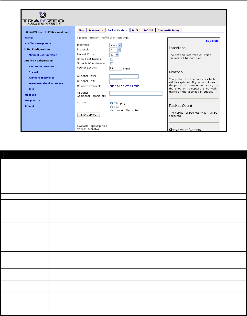
Chapter 19: Diagnostics Tools
TR0153 Rev. E1 146
Figure 66. Capturing network traffic
Option Description
Interface
Selects the interface from which packets are captured. Note that some packets may be
available on multiple interfaces. For example, data from a client device connected to
wlan1 destined for a device on the Internet will pass through wlan1 and either the wired
interface on a gateway device or the mesh interface on a repeater device
Protocol Data can be captured for the following protocols: TCP, UDP, ICMP, and ARP. Set the
value to “all” if you do not wish to filter out packets based on protocol type.
Packet Count Sets the number of packets to capture. The provided settings are 20, 50, 100, and 500.
Show Host Names Captured data will show resolved host names instead of IP addresses when this option is
selected.
Show MAC
addresses
In addition to IP address or hostnames, source and destination MAC addresses will be
displayed for each packet when this option is selected.
Packet Length
Sets the length of each packet that should be captured. If you are only interested in the
header contents of a packet, this value can be lowered to reduce the size of the data
capture file. If it is set to too low of a value, critical data may be not be captured though.
Optional Host Sets a host name or IP address to use for filtering purposes. All packets with this host as
their source OR destination address will be captured.
Optional Port
Sets a port to use for filtering purposes. All packets with this port as their source OR
destination port will be captured. NOTE: this setting only has an effect on capture of TCP
or UDP packets.
Common Protocols Click on the protocol names listed to add filtering parameters for them in the “Additional
Parameters” text box. It is possible to select more than one protocol to filter on.
Optional Additional
Parameters
The underlying application used to capture packets is tcpdump. Use this field to specify
additional parameters to tcpdump that are not made available through the GUI.
Output
Select whether to display the data on the webpage or to save it to a file, which can be
downloaded from the device. The file name format used is “<file
prefix>_MMDDYYY.HHMM.
Output File Prefix Sets an optional file prefix for saved files.
Table 16. Packet capture options
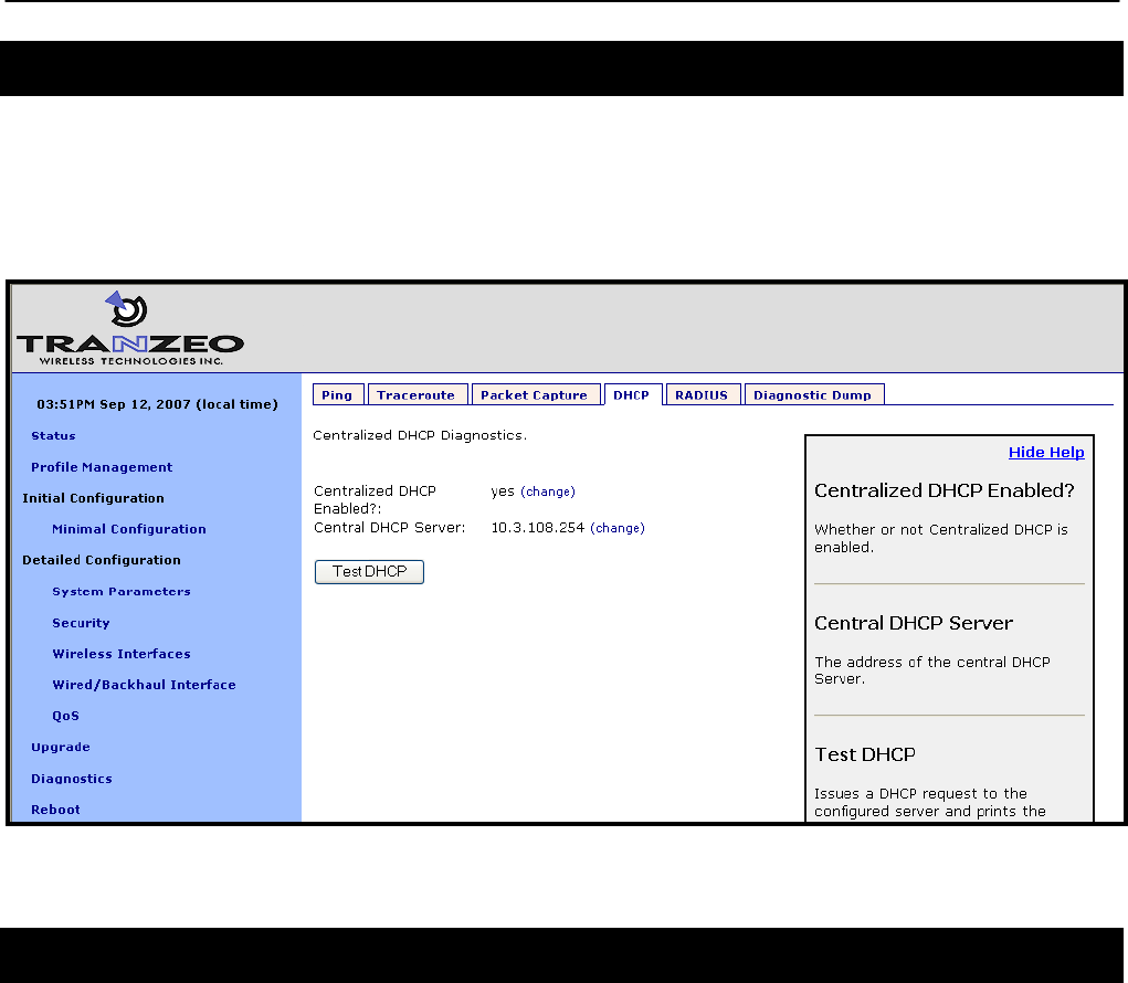
Chapter 19: Diagnostics Tools
TR0153 Rev. E1 147
19.4 Centralized DHCP Testing
The “DHCP” tab on the “Diagnostics” page can be used to test access to an external DHCP
server when the EnRoute500 is in centralized DHCP server mode (see Figure 67). Click on the
“Test DHCP” button to initiate a test. The results of the test will be displayed at the bottom of
the page.
Figure 67. Testing the connection to an external DHCP server
19.5 RADIUS Server Testing
The “RADIUS” tab on the “Diagnostics” page can be used to test authentication of credentials
by a RADIUS servers used for splash page or WPA authentication (see Figure 68). Use the
procedure below to test the validity of credentials with a RADIUS server.
1. Select the RADIUS server you want to use for the test from the drop-down menu
2. Enter the credentials you want to test in the “Username” and “Password” fields
3. Click on the “Test User” button
The results of the test will be displayed at the bottom of the page. Three outcomes are
possible:
• The credentials were authenticated by the server
• Communication was established with the server, but the credentials were not valid
• It was not possible to establish communication with the server
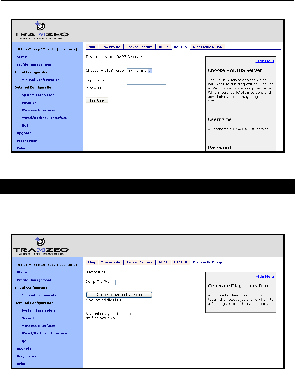
Chapter 19: Diagnostics Tools
TR0153 Rev. E1 148
Figure 68. Testing credentials with a RADIUS server
19.6 Diagnostic Dump
The “Diagnostic Dump” tab on the “Diagnostics” page allows the user to create a snapshot of
diagnostic data that can be downloaded to a PC and sent to Tranzeo technical support for
analysis (see Figure 69).
Figure 69. Generating a diagnostic dump

Chapter 19: Diagnostics Tools
TR0153 Rev. E1 149
The list of diagnostic dumps available for download is displayed at the bottom of the page. The
diagnostic dumps can be downloaded by clicking on the filenames. To delete one or more
diagnostic dumps, select the check boxes next to the ones you wish to delete and then click on
the “Delete Selected” button.

Chapter 20:Firmware Management
TR0153 Rev. E1 150
20 Firmware Management
20.1 Displaying the Firmware Version
The firmware version string contains the following information:
• Build date
• Major version number
• Minor version number
• Build number
These values are embedded in the version string as follows:
enroute500_< Build date >_< Major version >_< Minor version >_< Build number>
CLI
Firmware version information is available in the ‘version’ interface. The example below shows
how to display the current firmware version.
> use version
version> get release
release = ENROUTE500_20060419_00_00_0133
Web GUI
The firmware version is displayed at the top of the “Status” page accessible via the web
interface.
20.2 Upgrading the Firmware
The EnRoute500 supports secure remote firmware upgrade.
When upgrading the firmware, it is important to upgrade the firmware on all
devices in a mesh neighborhood.
Prior to upgrading firmware, please contact Tranzeo technical support to find
out if there are any version-specific instructions for upgrading from the
firmware version you are currently using.
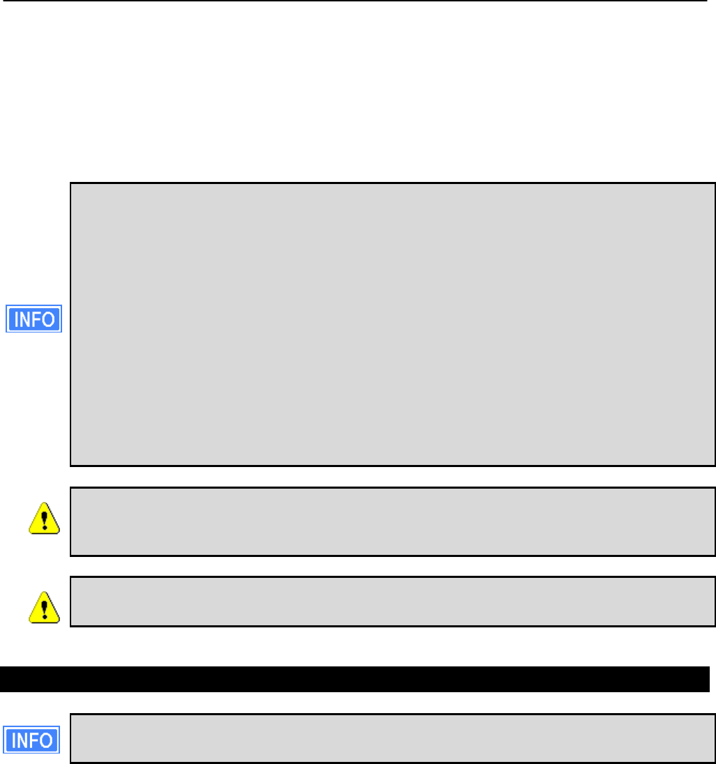
Chapter 20:Firmware Management
TR0153 Rev. E1 151
There are two approaches for upgrading the firmware of a number of devices in a mesh
neighborhood:
• Upgrade the firmware on each device individually
• Upgrade the firmware for the entire mesh neighborhood from the mesh gateway
The latter method is the recommended approach.
The primary benefit of using the mesh neighborhood upgrade approach is that the
gateway will determine the order in which it should start the upgrades of devices in
the mesh based on their relative connectivity. If each device is upgraded manually,
the user must determine the connectivity between devices to ensure that they are
upgraded in an order such that connectivity to devices isn’t broken. For example,
consider the following scenario:
• Device 1 is a gateway
• Device 2 is a repeater connected to device 1
• Device 3 is a repeater connected to device 2
If the upgrade of device 2 is started before the upgrade of device 3, the connection
to device 3 from the gateway will be lost, preventing the user from connecting to that
device.
At least the gateway device must have access to the Internet, and specifically
the Tranzeo upgrade server, to complete an upgrade unless the upgrade
image has already been downloaded to the device’s non-volatile memory.
If power to the EnRoute500 is lost during the upgrade process, it is possible
that the device will become inoperable.
20.2.1 Upgrading the Firmware on all Devices in a Mesh Neighborhood
The web GUI page for upgrading all devices in a mesh neighborhood is only
available on devices configured as gateways.
It is possible to control the firmware upgrade of all devices in a mesh neighborhood from the
“Upgrade Mesh” tab on the “Upgrade” page. This page displays the following information:
• Firmware available on the remote upgrade server
• Firmware available in the non-volatile memory of the EnRoute500
• Devices in the mesh neighborhood
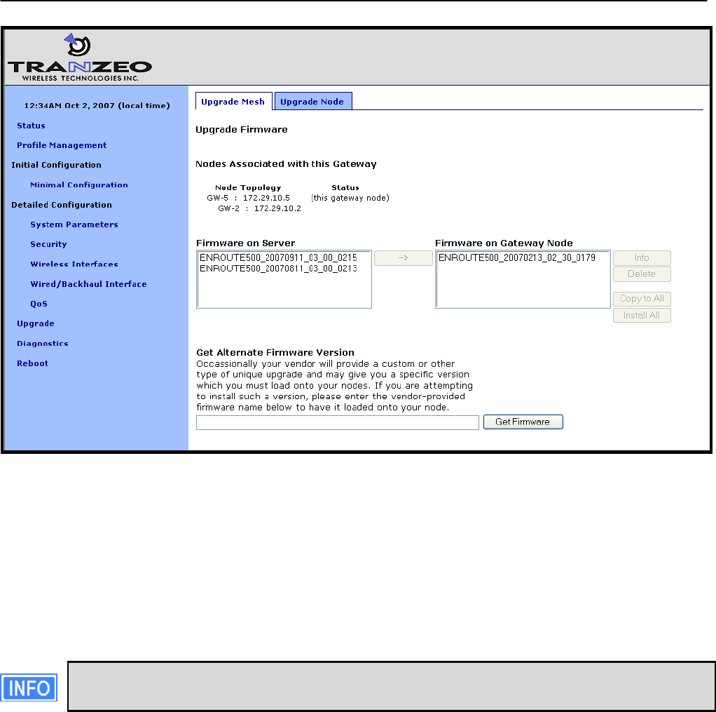
Chapter 20:Firmware Management
TR0153 Rev. E1 152
Figure 70. Updating firmware on all devices in a mesh neighborhood
Follow the procedure below to upgrade the devices in a mesh neighborhood:
1. Select the firmware version you want to upgrade to from the “Firmware on Server” box
2. Click on the button with the arrow to the right of the “Firmware on Server” box. This will
begin the download process of the firmware from the Tranzeo upgrade server to the
non-volatile memory on the EnRoute500. While the firmware is downloading, it will be
shown in blue in the “Firmware on Gateway Node” box.
If the completion percentage does not update, click on the “Upgrade Node” tab to
update it.
3. When the download has been completed, verify that all the devices you wish to update
are listed under the “Nodes Associated with this Gateway” heading. If they are proceed
to the next step.
4. Select the firmware you wish to upgrade to from the “Firmware on Gateway Node” box.
5. Click on the “Copy to All” button. The upgrade image will be copied to the devices in the
mesh that do not already have it. Text indicating progress will be displayed next to the
device IP address under the “Nodes Associated with this Gateway” heading (“files being
copied”, “copy completed”, and finally “READY TO BE UPGRADED”).
6. Again, select the firmware you wish to upgrade to from the “Firmware on Gateway
Node” box.
Chapter 20:Firmware Management
TR0153 Rev. E1 153
7. Click on “Install All”. Text indicating that the node is being upgraded will be displayed
next to the device IP address under the “Nodes Associated with this Gateway” heading.
8. Wait for the upgrade to complete (approximately 20 minutes).
20.2.2 Upgrading the Firmware on an Individual Device
The firmware can be upgraded on an individual device using the “Upgrade Node” tab on the
“Upgrade” page. This is the only tab that is available on devices configured as repeaters. This
page displays the following information:
• Firmware currently installed on the EnRoute500
• Firmware available on the remote upgrade server
• Firmware available in the non-volatile memory of the EnRoute500
• Space used/available in non-volatile memory for storing upgrade images
Caution should be used when updating the firmware on a single device in a
mesh neighborhood. It is advisable to upgrade the devices that are the most
hops away from a gateway first and keep upgrading devices that are
successively closer to the gateway, upgrading the gateway firmware last.
Follow the procedure below to upgrade the firmware on a device:
1. Select the firmware version you want to upgrade to from the “Firmware on Server” box
2. Click on the button with the arrow to the right of the “Firmware on Server” box. This will
begin the download process of the firmware from the Tranzeo upgrade server to the
non-volatile memory on the EnRoute500. While the firmware is downloading, it will be
shown in blue in the “Firmware on Gateway Node” box.
If the completion percentage does not update, click on the “Upgrade Node” tab to
update it.
3. When the download has been completed, select the firmware you wish to upgrade to
from the “Firmware on Node” box.
4. Click on the “Install” button.
5. Wait for the install to complete. The EnRoute500 will reboot automatically when the
upgrade has been completed.
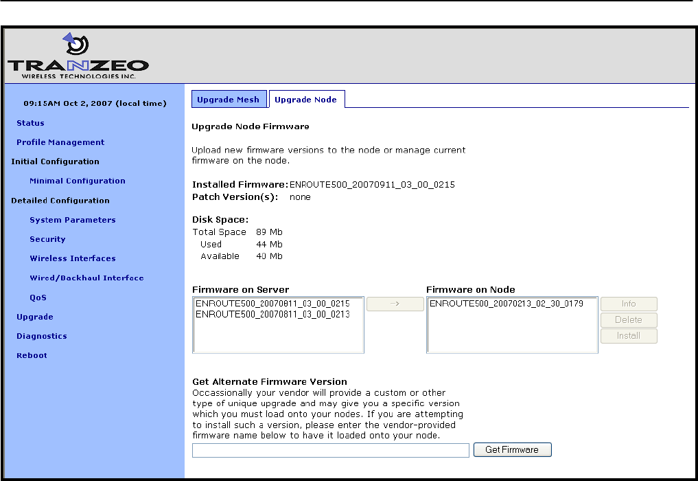
Chapter 20:Firmware Management
TR0153 Rev. E1 154
Figure 71. Updating firmware on a single device

Glossary
TR0153 Rev. E1 155
Glossary
Client access
interface
An interface on the EnRoute500 used by a client device, such as an
802.11-enabled laptop, to connect to the EnRoute500. The client
access interfaces are the virtual APs wlan1 – wlan4 and, on devices
configured as repeaters, the eth0 Ethernet interface.
Client address
scheme
The method used to assign address spaces to client address
interfaces. The two supported client address schemes are implicit and
explicit.
Client device A device that is connected to one of the EnRoute500’s client access
interfaces, e.g. a laptop
Mesh neighborhood A group of two or more EnRoute500 nodes with at least one
configured as a gateway
Mesh gateway A mesh node that, in addition to relaying traffic between neighboring
mesh nodes and supporting wireless clients through its built-in APs,
acts as the layer 3 gateway for a mesh neighborhood
Mesh node A single EnRoute500 that is part of a mesh neighborhood
Mesh repeater A mesh node that relays traffic to neighboring mesh nodes and
supports wireless and wired clients.
Virtual access point An access point that shares a single AP radio with one or more
access points.

Abbreviations
TR0153 Rev. E1 156
Abbreviations
ACL Access Control List
AP Access Point
CLI Command line interface
ESSID Extended Service Set Identifier
LAN Local-Area Network
NAT Network Address Translation
PoE Power over Ethernet
QoS Quality of Service
RSSI Received signal strength indicator
VAP Virtual Access Point
VLAN Virtual Local-Area Network
VPN Virtual Private Network
WAN Wide-Area Network
WLAN Wireless Local-Area Network
WPA Wi-Fi Protected Access
WPA-PSK Wi-Fi Protected Access Pre-Shared Key