Tranzeo Wireless Technologies PVE58XBY WIRELESS NETWORKING DEVICE User Manual
Tranzeo Wireless Technologies, Inc WIRELESS NETWORKING DEVICE Users Manual
UserManual.wiki
>
Tranzeo Wireless Technologies
>
PVE58XBY User Manual
>
Users Manual
Contents
1.
USERS MANUAL
2.
Users Manual
Users Manual
Navigation menu
Upload a User Manual
Namespaces
Wiki Guide
HTML
PDF
Info
Views
User Manual
Discussion / Help
Navigation
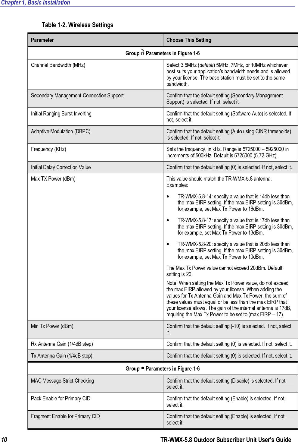
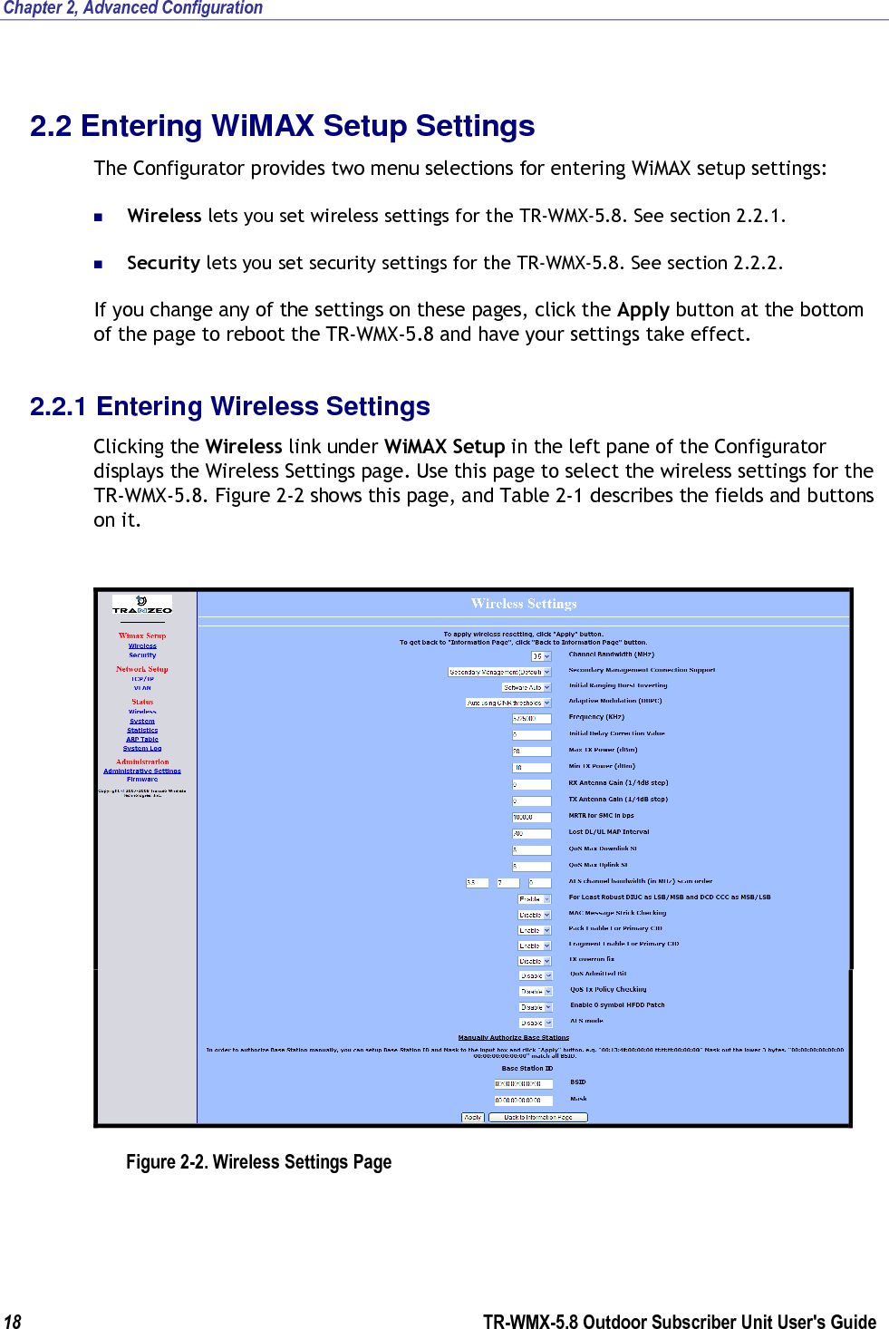
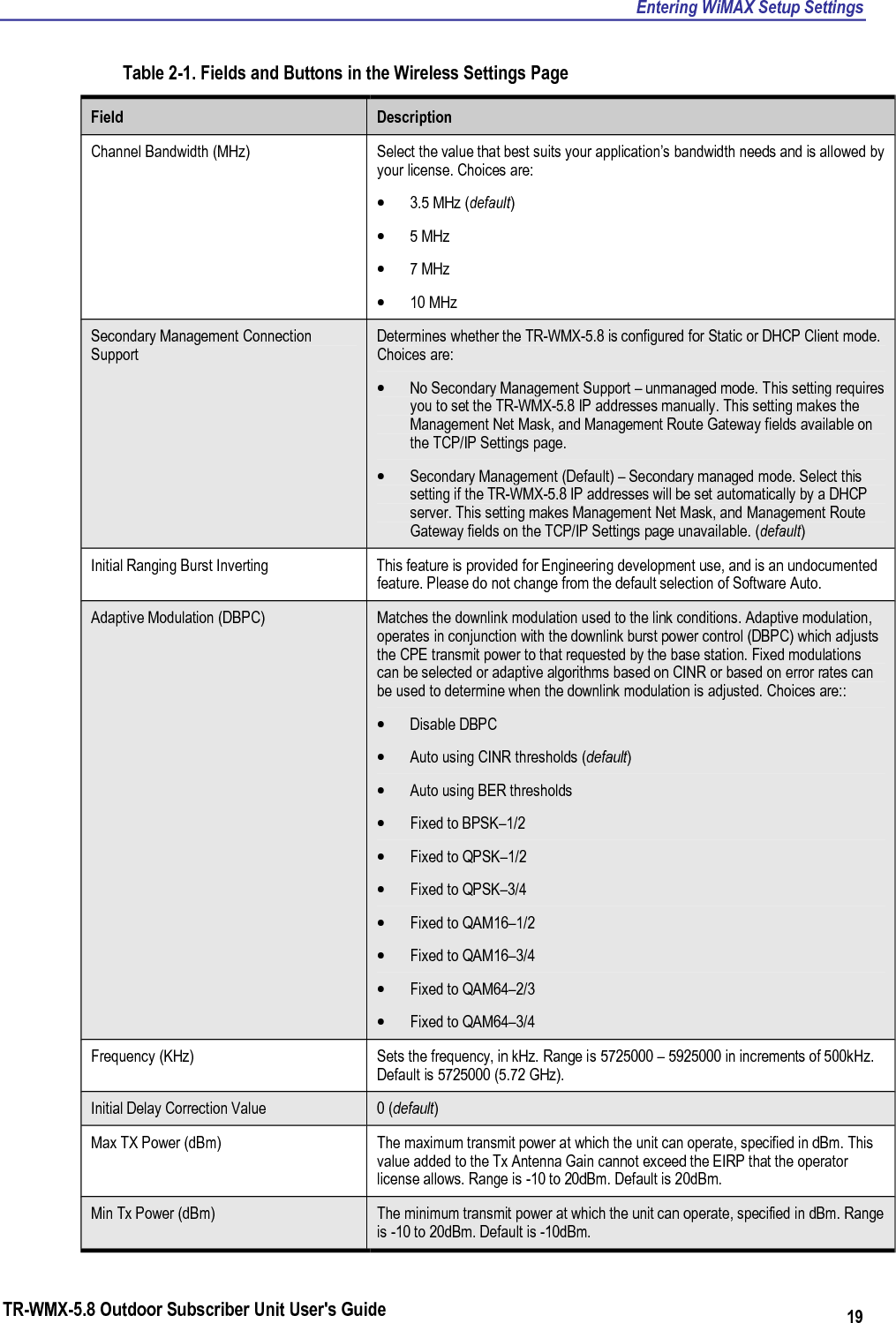
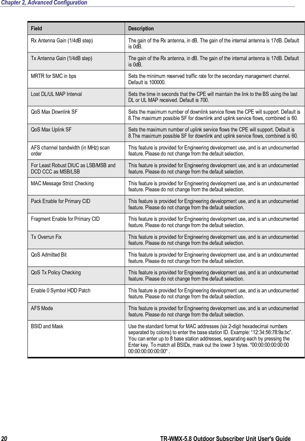
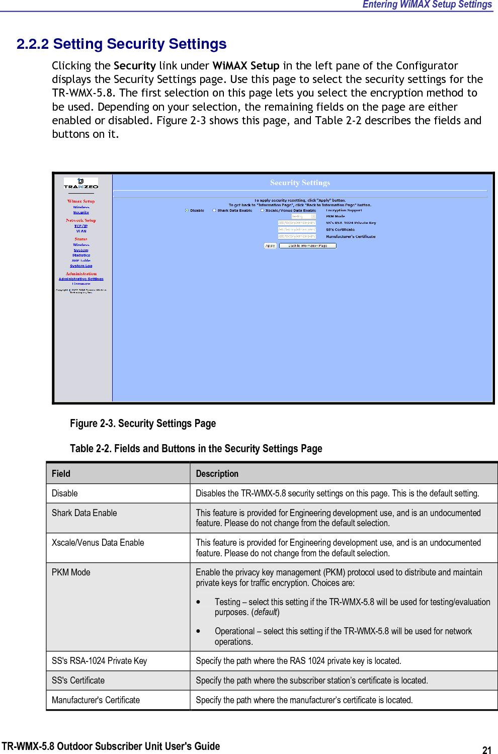
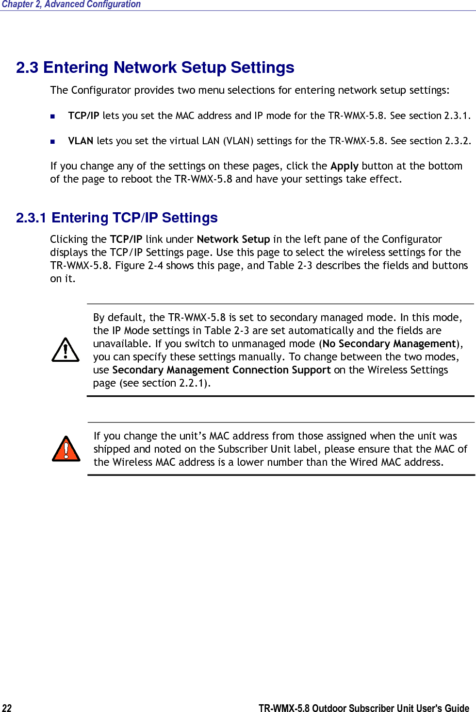
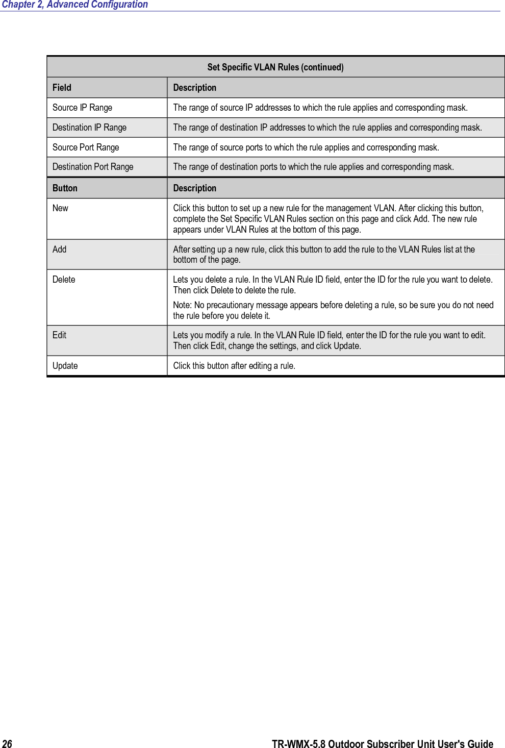
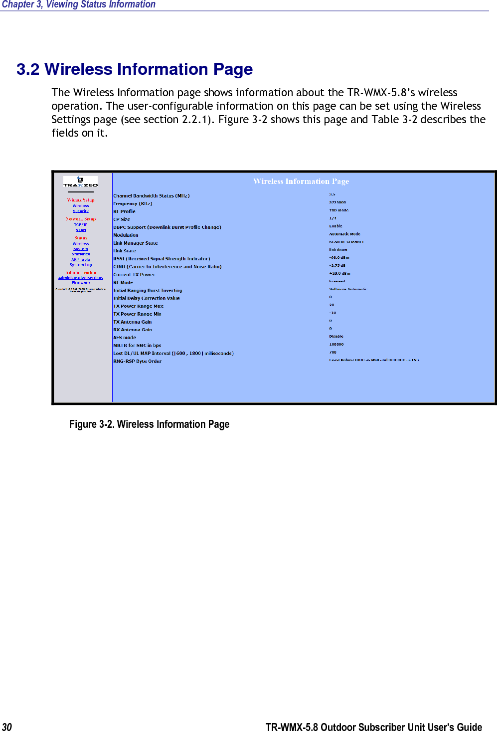
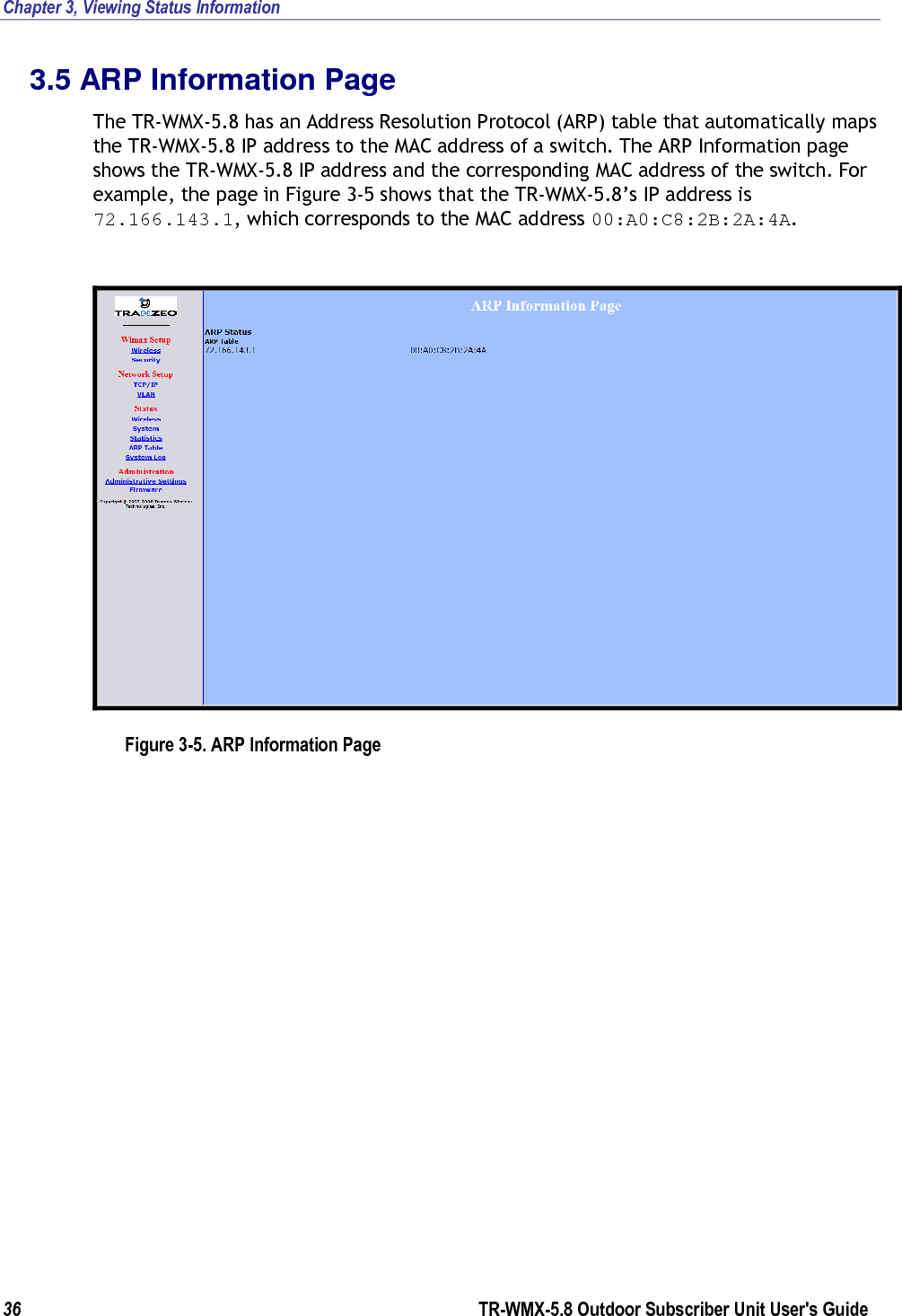
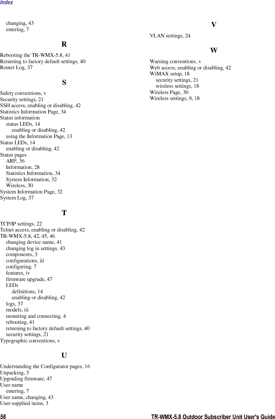
![Wireless Information Page TR-WMX-5.8 Outdoor Subscriber Unit User's Guide 31 Table 3-2. Wireless Information Page Field Description Channel Bandwidth Status (MHz) Bandwidth, in MHz, of theTR-WMX-5.8, as defined on the Wireless Settings page (see section 2.2.1). Frequency (KHz) Frequency, in kHz, of theTR-WMX-5.8, as defined on the Wireless Settings page (see section 2.2.1). RF Profile RF profile of theTR-WMX-5.8, as defined on the Wireless Settings page (see section 2.2.1). CP Size Cycle prefix size, as defined on the Wireless Settings page (see section 2.2.1). Modulation Modulation used by theTR-WMX-5.8. Link Manager State Shows where in the network connection process the CPE is. For example if the CPE is scanning for a BS downlink message, receiving a DHCP address assignment, or if the CPE to BS link is operational. Link State Shows whether the TR-WMX-5.8 link is up or down. RSSI (Received Signal Strength Indicator) Strength of the Received Signal Strength Indicator, in dBm, received by your TR-WMX-5.8. The higher the value, the higher the transmit rate (up to the maximum). Conversely, the lower the RSSI, the lower the transmission speed until 0 is reached (no connectivity). CINR (Carrier to Interference and Noise Ratio) Carrier to Interference and Noise Ratio, in dB, for your TR-WMX-5.8. The higher the value, the more throughput a link can maintain. Current TX Power Current transmit power, in dBm, for your TR-WMX-5.8. RF Mode Current radio-frequency mode (licensed or unlicensed) for your TR-WMX-5.8. Initial Ranging Burst Inverting This feature is provided for Engineering development use, and is an undocumented feature. Initial Delay Correction Value This feature is provided for Engineering development use, and is an undocumented feature. TX Power Range Max The maximum transmit power range of the TR-WMX-5.8, as defined on the Wireless Settings page (see section 2.2.1). TX Power Range Min The minimum transmit power range of the TR-WMX-5.8, as defined on the Wireless Settings page (see section 2.2.1). TX Antenna Gain The maximum transmit antenna gain of the TR-WMX-5.8, as defined on the Wireless Settings page (see section 2.2.1). RX Antenna Gain The minimum transmit antenna gain of the TR-WMX-5.8, as defined on the Wireless Settings page (see section 2.2.1). AFS Mode This feature is provided for Engineering development use, and is an undocumented feature. MRTR for SMC in bps The minimum reserved traffic rate for the secondary management channel. Lost DL/UL MAP Interval ([600 , 1800] milliseconds) The time in seconds that the CPE will maintain the link to the BS using the last DL or UL MAP received. RNG-RSP Byte Order This feature is provided for Engineering development use, and is an undocumented feature.](https://usermanual.wiki/Tranzeo-Wireless-Technologies/PVE58XBY.Users-Manual/User-Guide-1227797-Page-41.png)