Tranzeo Wireless Technologies RAKT3KN2 WIRELESS MESH ROUTER User Manual USERS MANUAL 1
Tranzeo Wireless Technologies, Inc WIRELESS MESH ROUTER USERS MANUAL 1
UserManual.wiki
>
Tranzeo Wireless Technologies
>
RAKT3KN2 User Manual
>
USERS MANUAL 1
Contents
1.
USERS MANUAL 1
2.
USERS MANUAL 2
USERS MANUAL 1
Navigation menu
Upload a User Manual
Namespaces
Wiki Guide
HTML
PDF
Info
Views
User Manual
Discussion / Help
Navigation
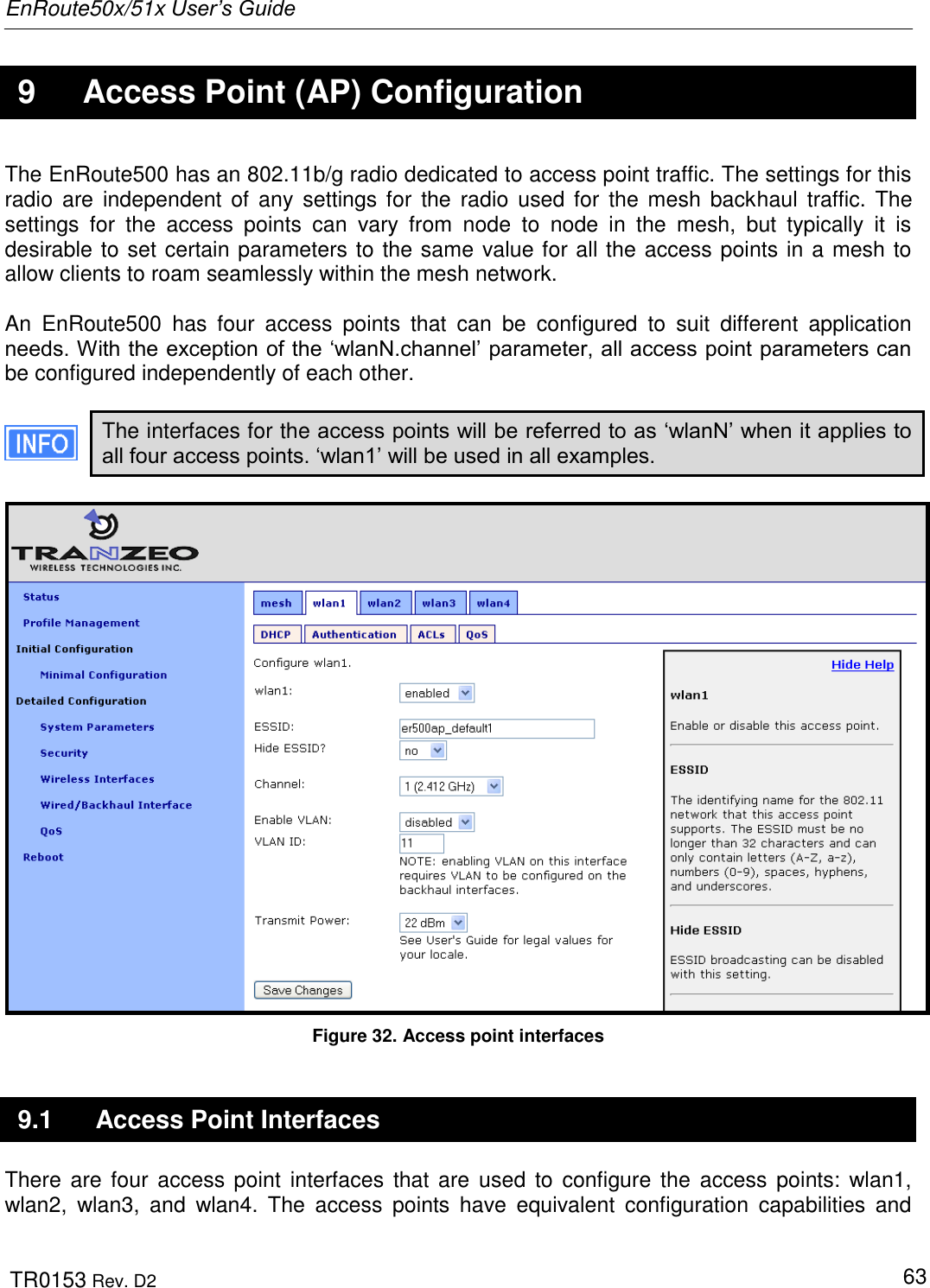
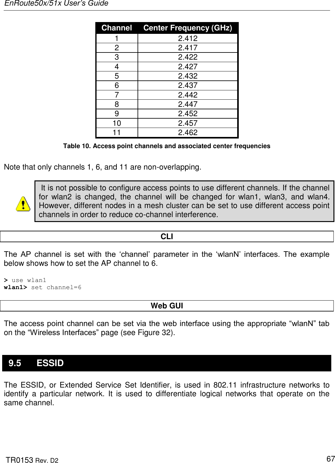
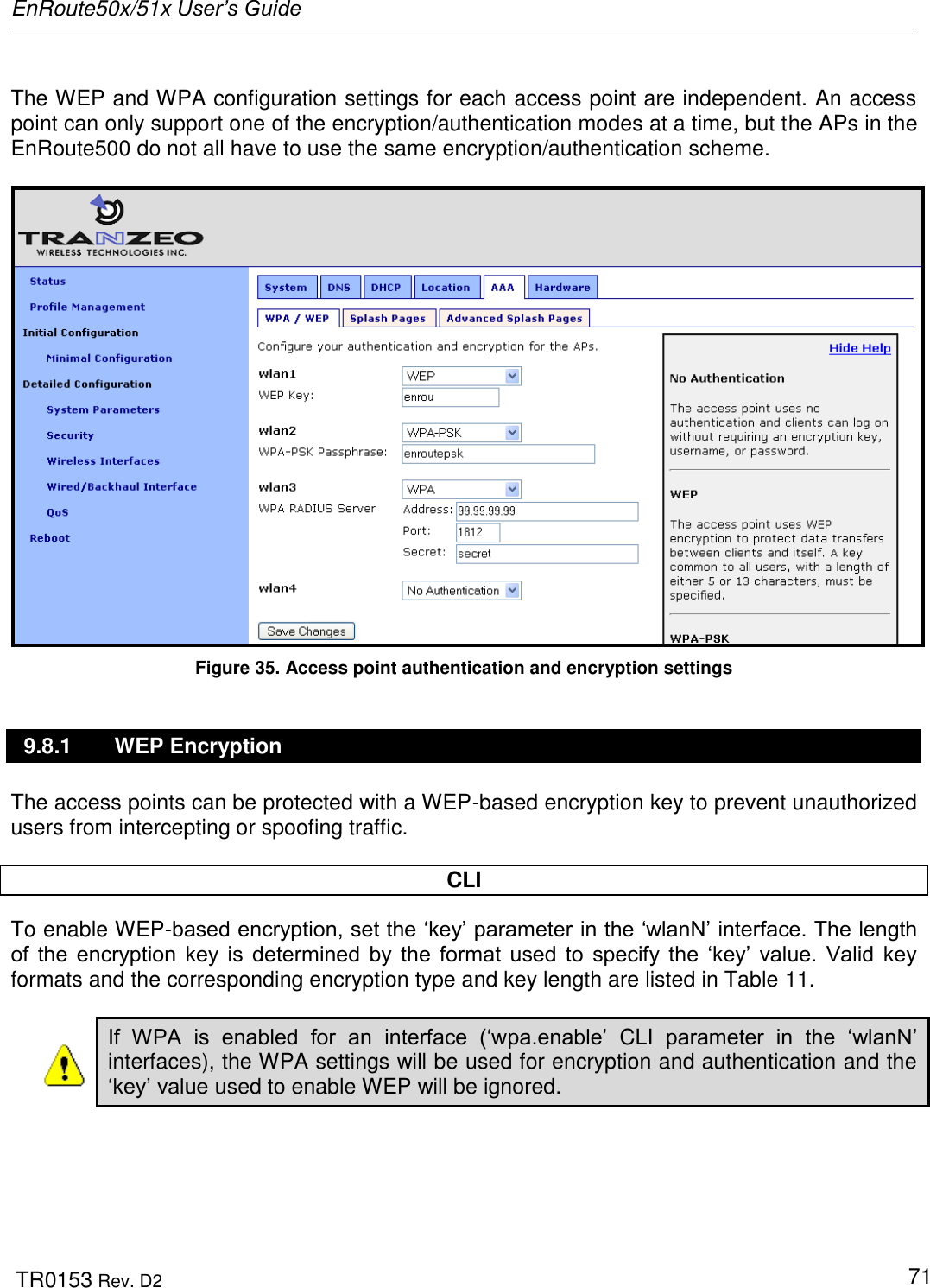
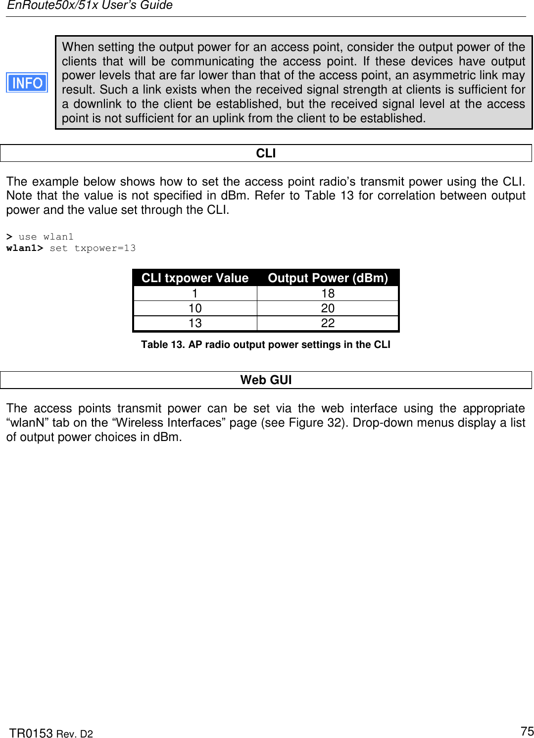
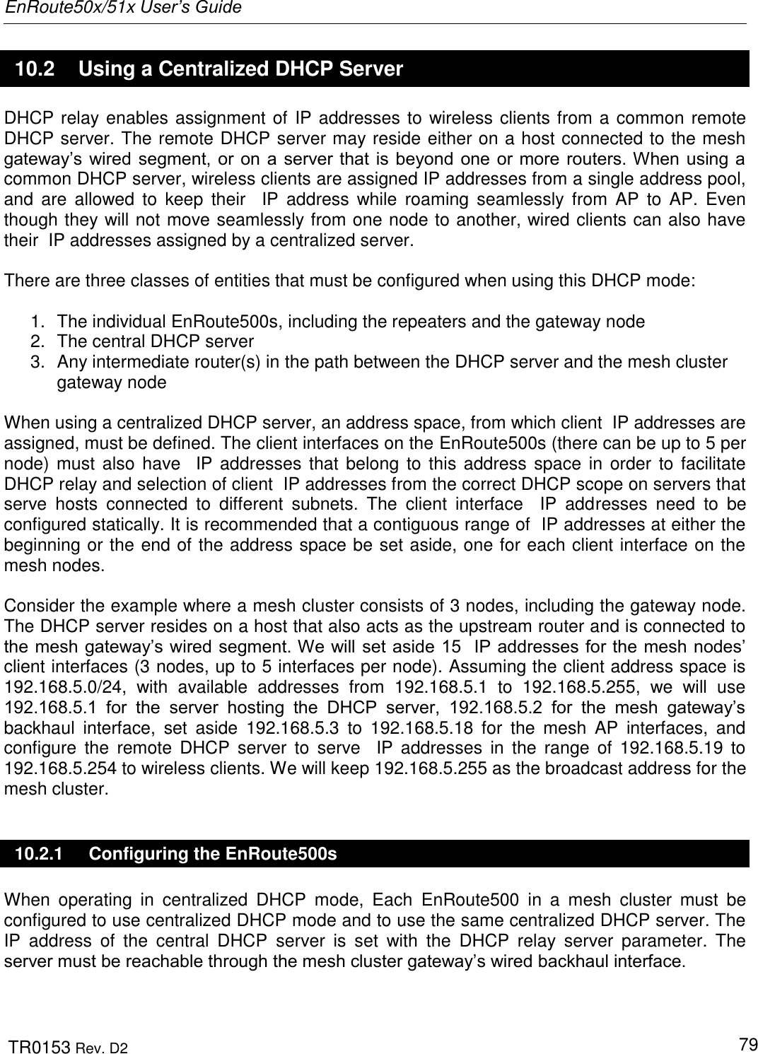
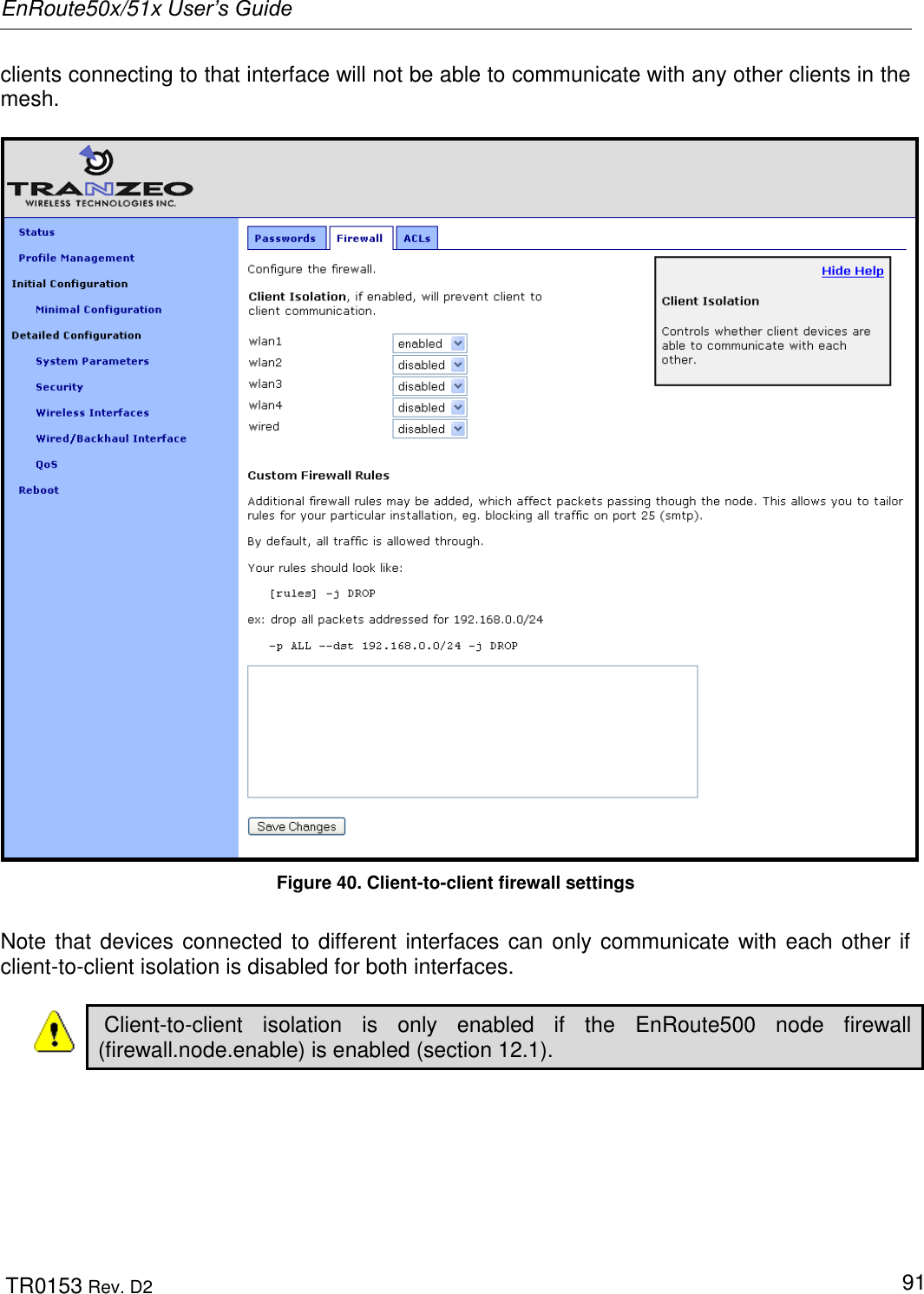
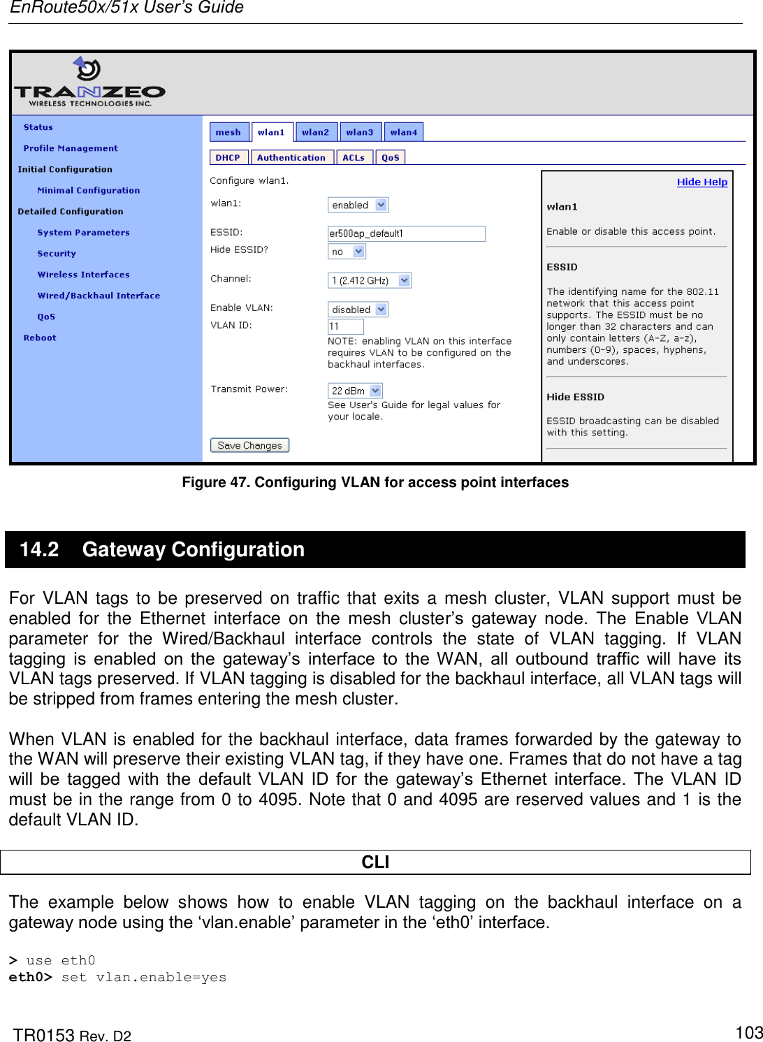
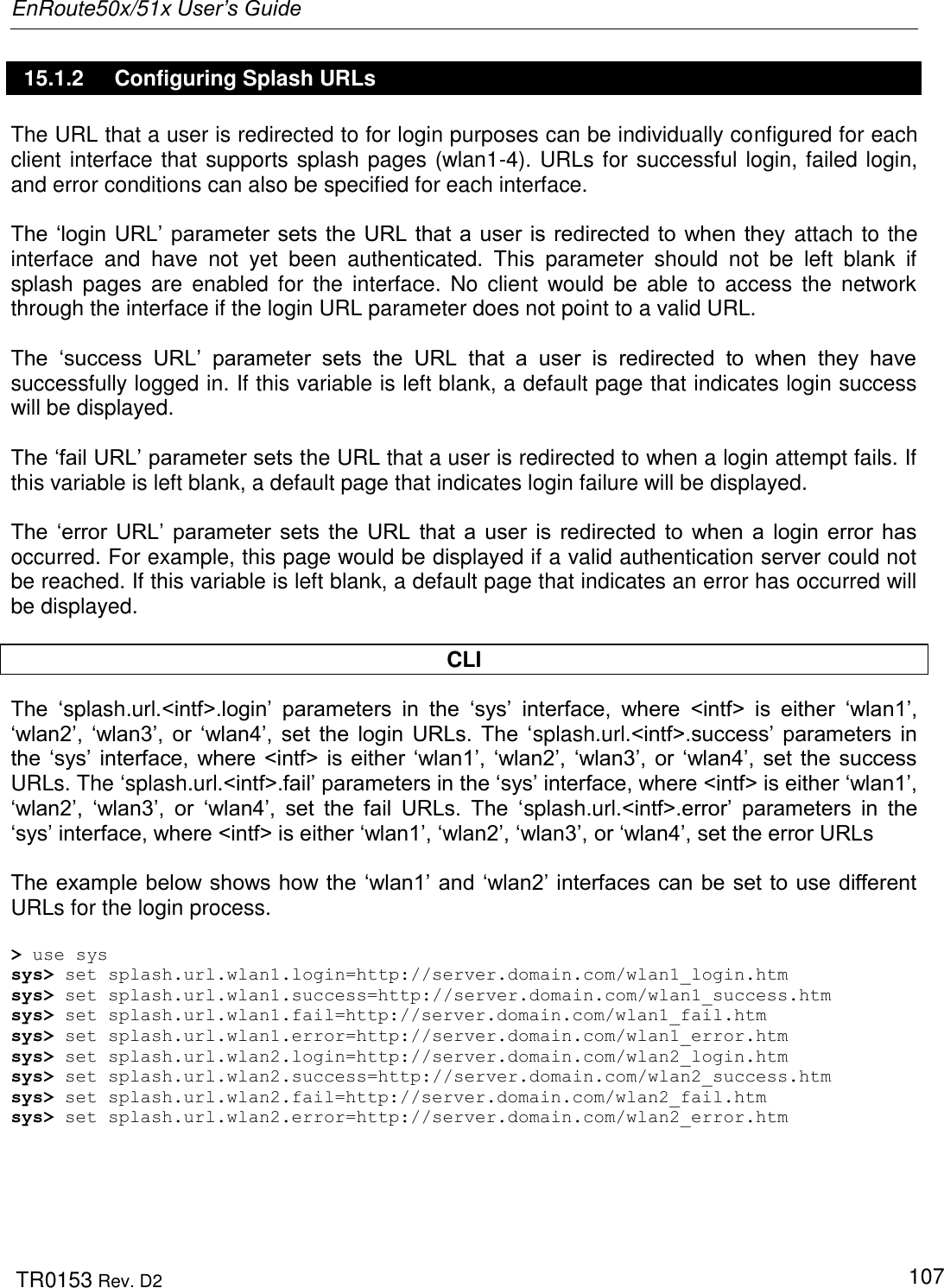
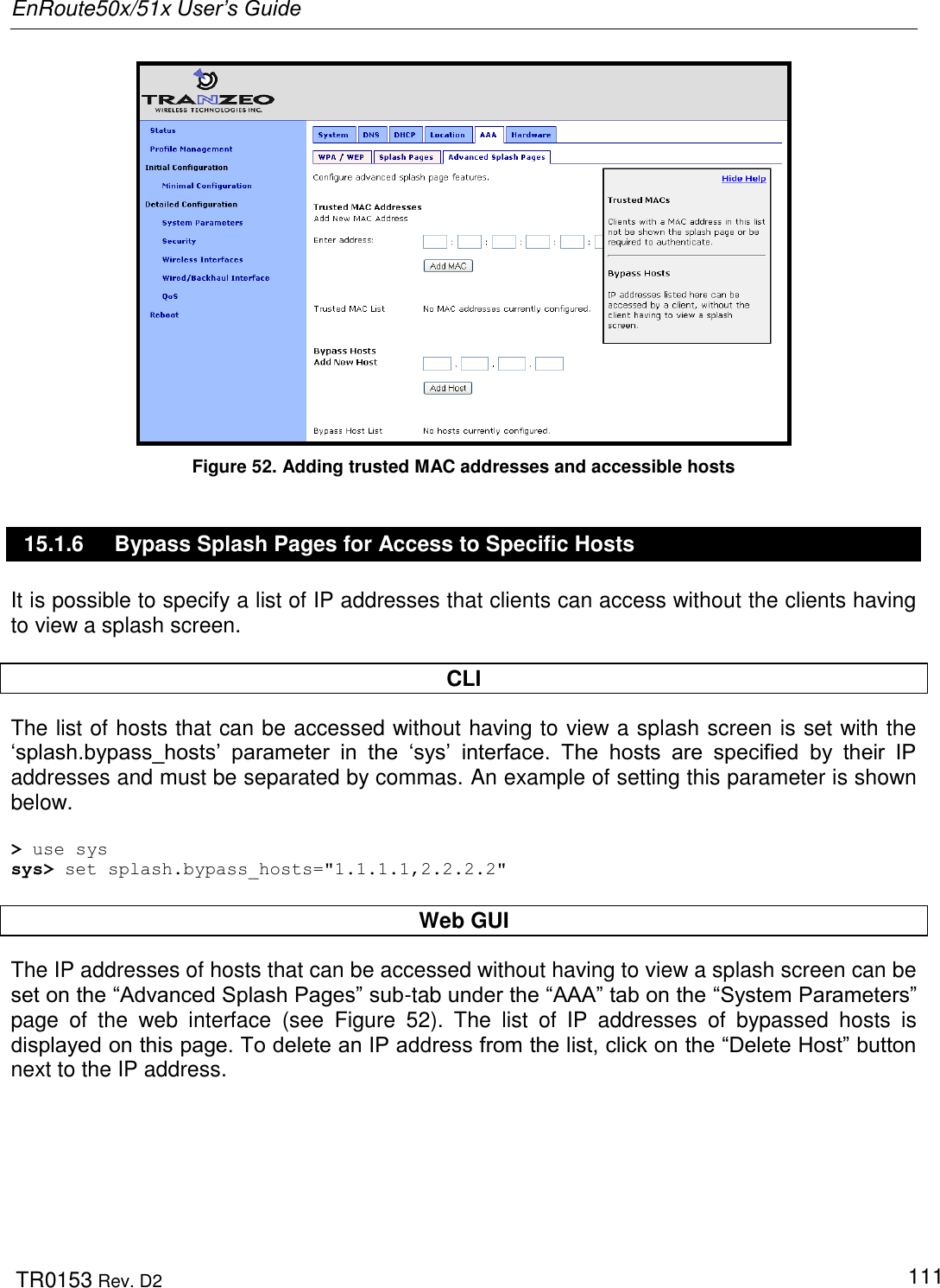
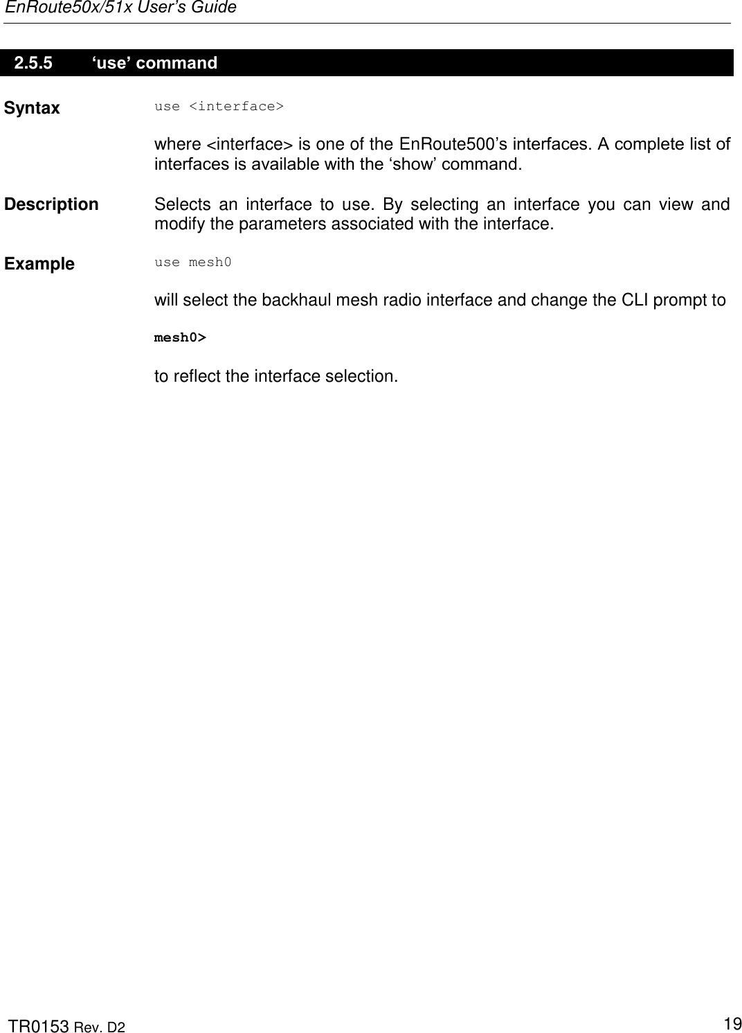
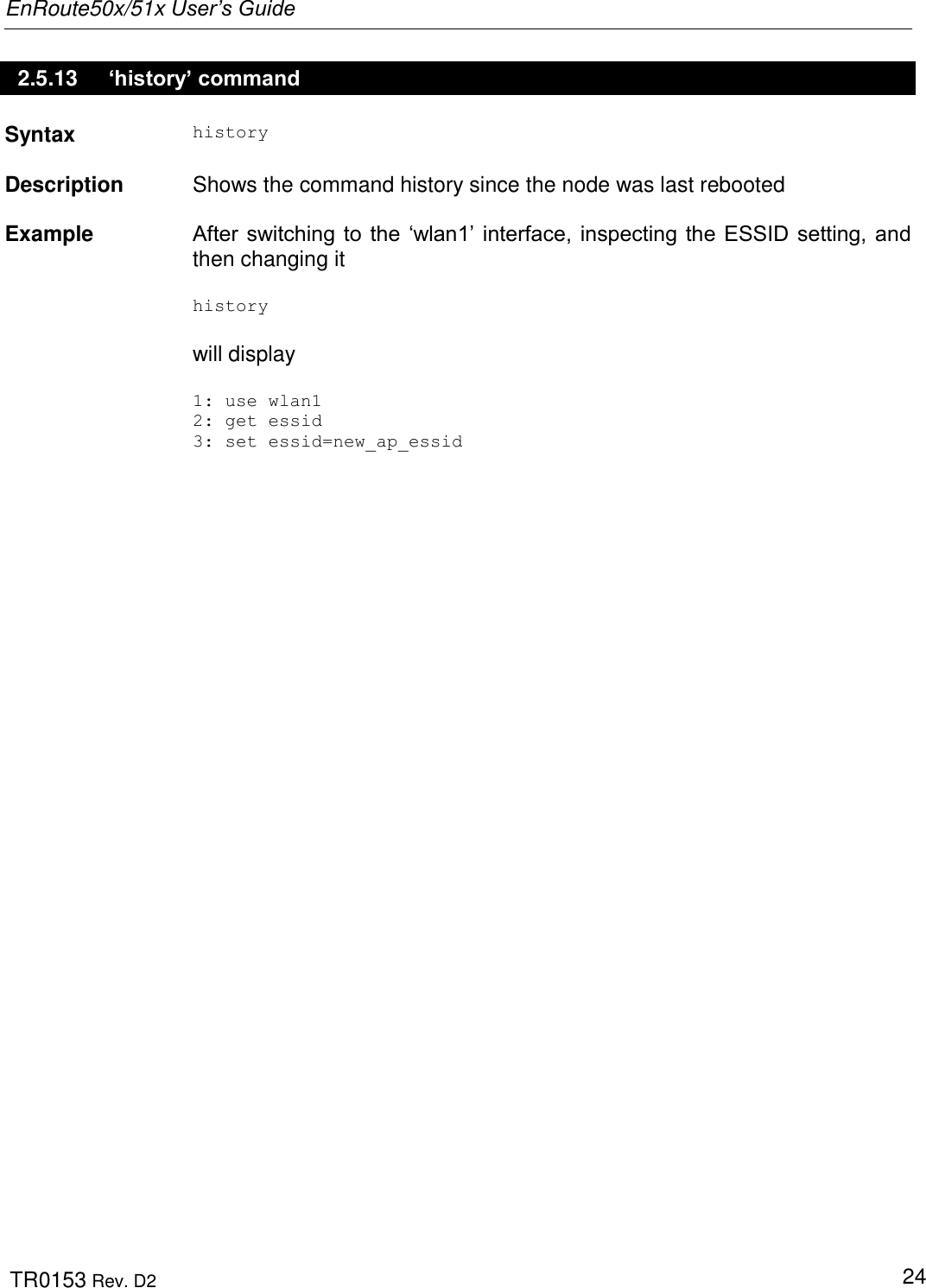
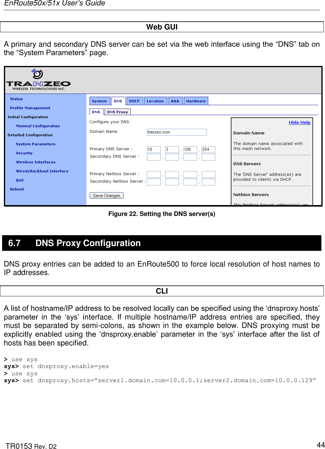
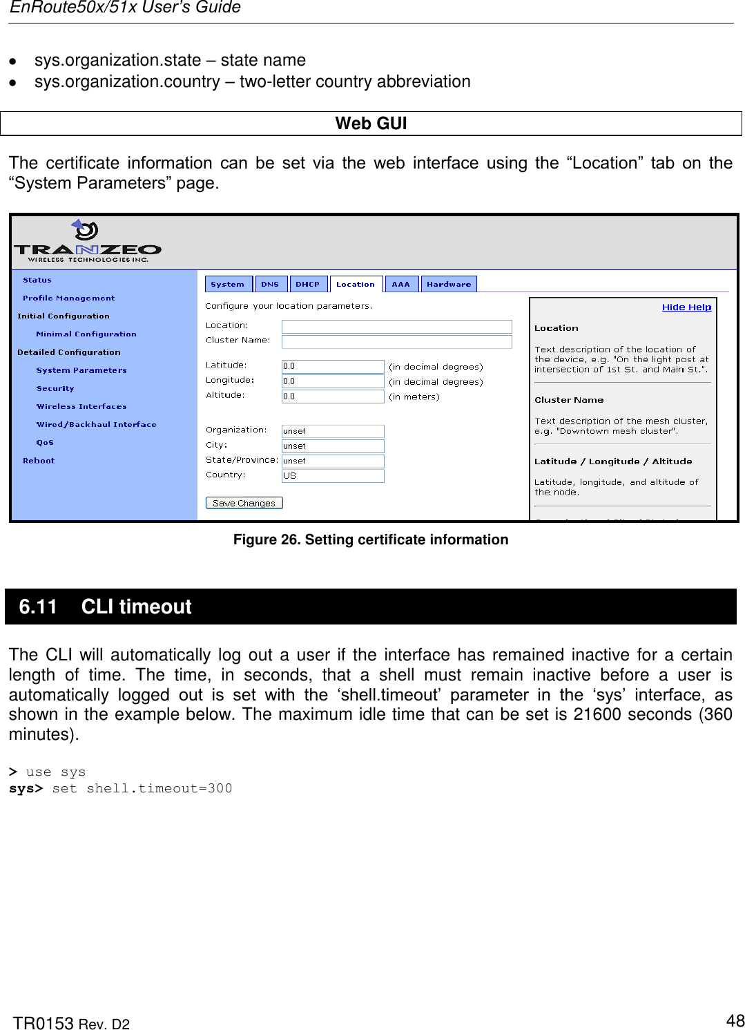
![EnRoute50x/51x User’s Guide TR0153 Rev. D2 17 2.4.2 Cancel a Command Ctrl+C cancels the input on the current command line and moves the cursor to a new, blank command line. 2.4.3 Searching the Command History The command history can be searched by pressing Ctrl+R and entering a search string. The most recently executed command that matches the string entered will be displayed. Press „Enter‟ to execute that command. 2.4.4 Executing a Previous Command By using the up and down arrow keys you can select previously executed commands. When you find the command you wish to execute, you can either edit it or press „Return‟ to execute it. 2.5 CLI Commands The usage of all CLI commands is explained in the following subsections. The command syntax used is command <mandatory argument> command [optional argument] 2.5.1 ‘?’ command Syntax ? Description Pressing „?‟ at any time in the CLI will display a help menu that provides an overview of the commands that are described in this section. It is not necessary to press „Enter‟ after pressing „?‟. 2.5.2 ‘whoami’ command Syntax whoami Description Displays the name of the user you are logged in as.](https://usermanual.wiki/Tranzeo-Wireless-Technologies/RAKT3KN2.USERS-MANUAL-1/User-Guide-797586-Page-17.png)
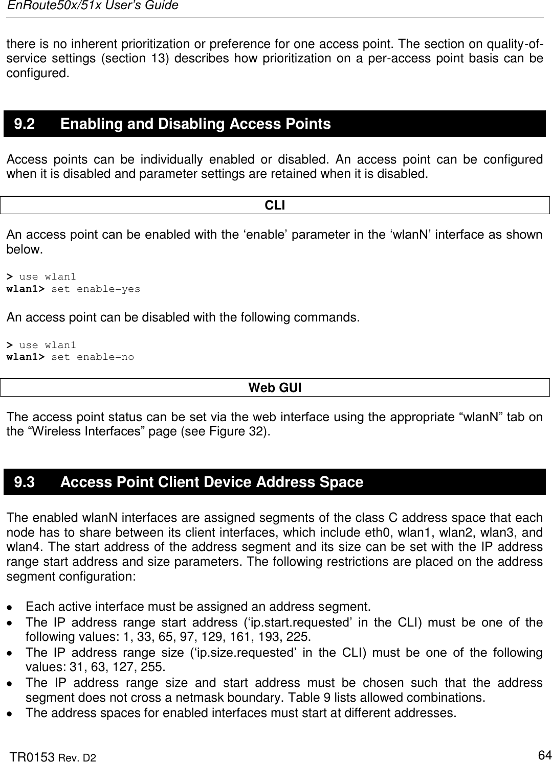
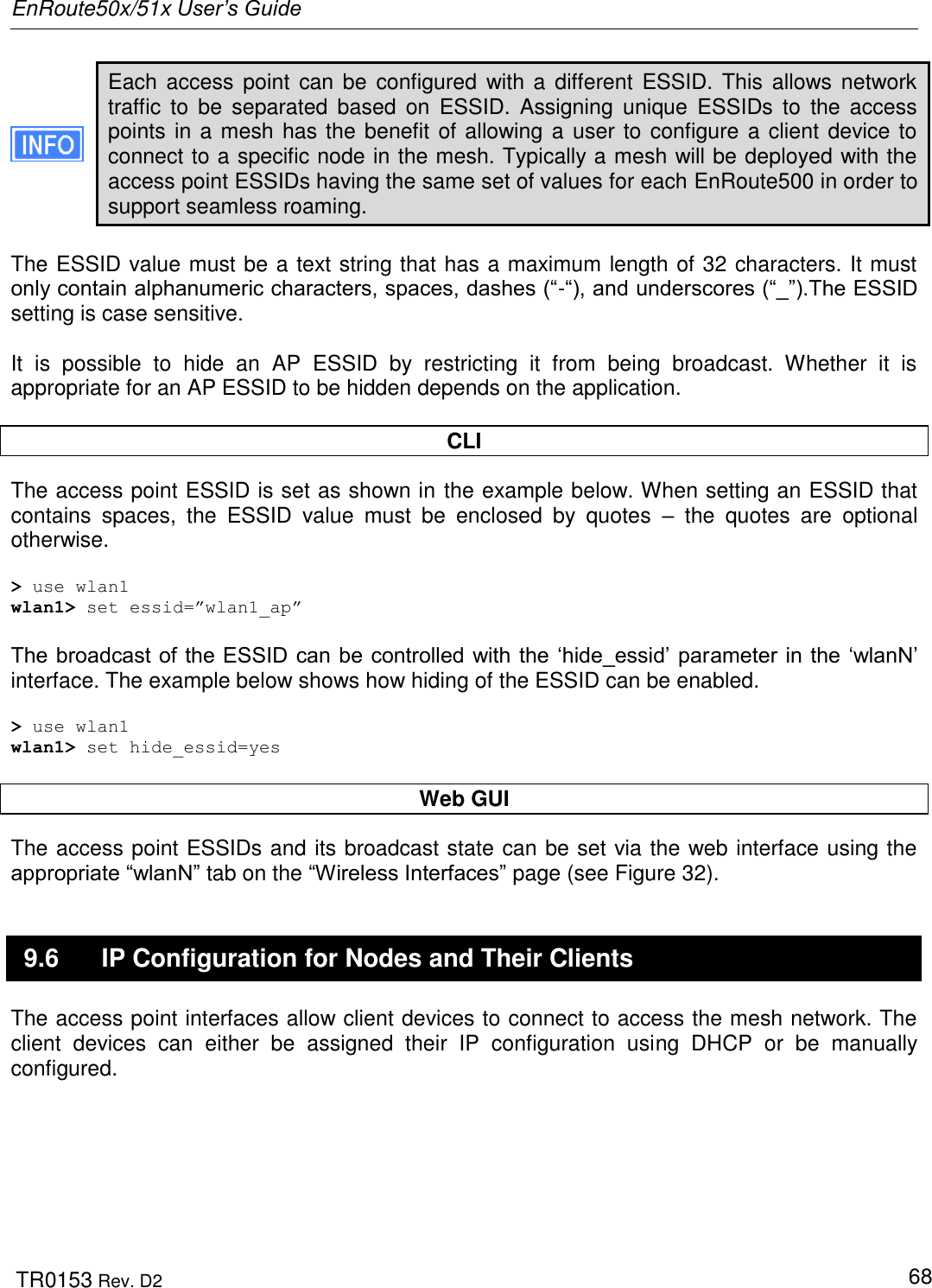
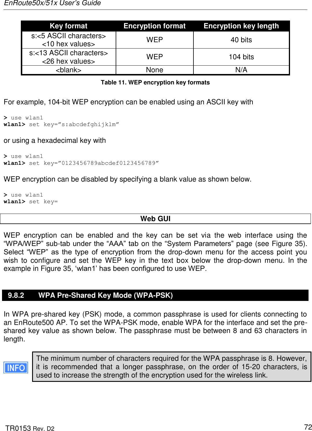
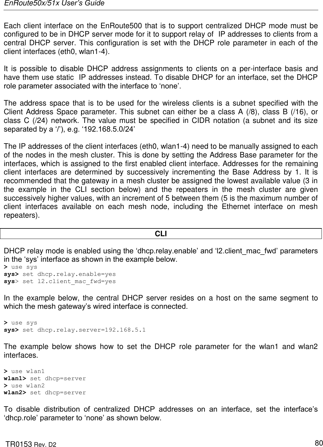
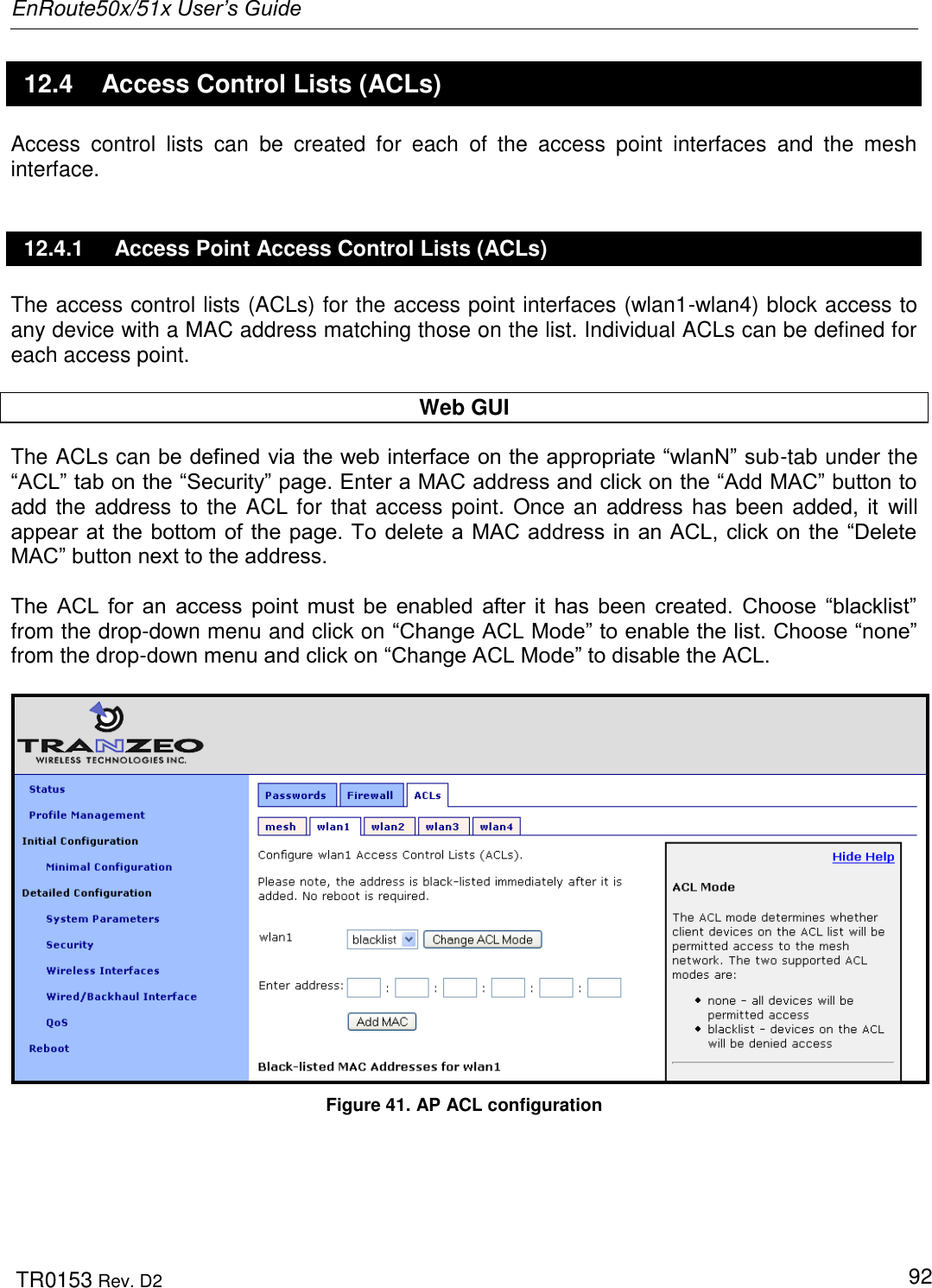
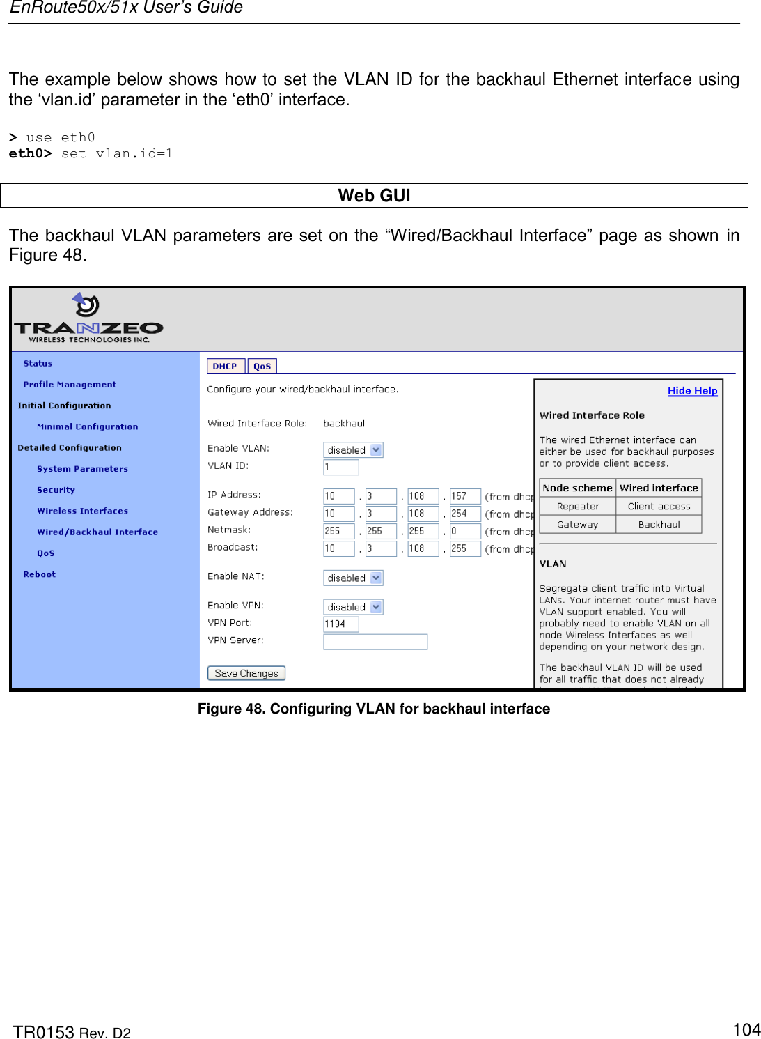
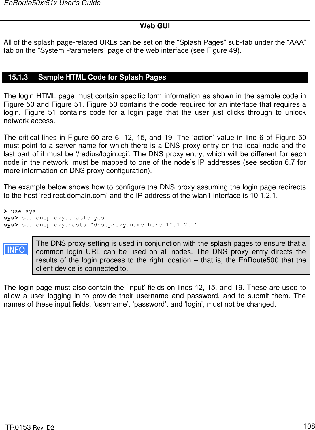
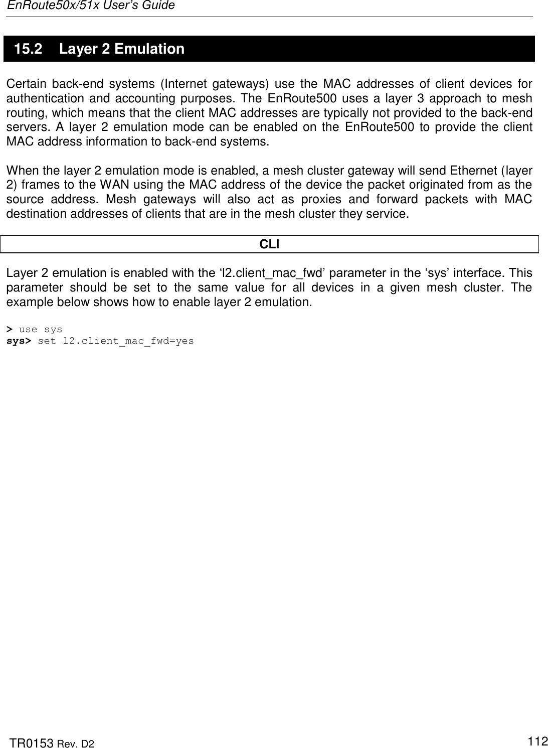
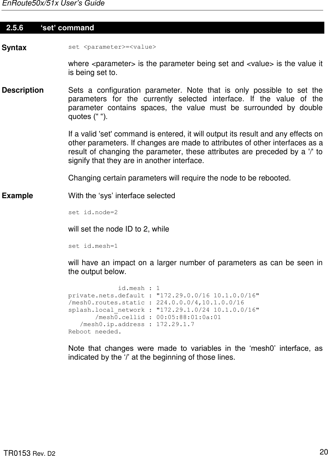
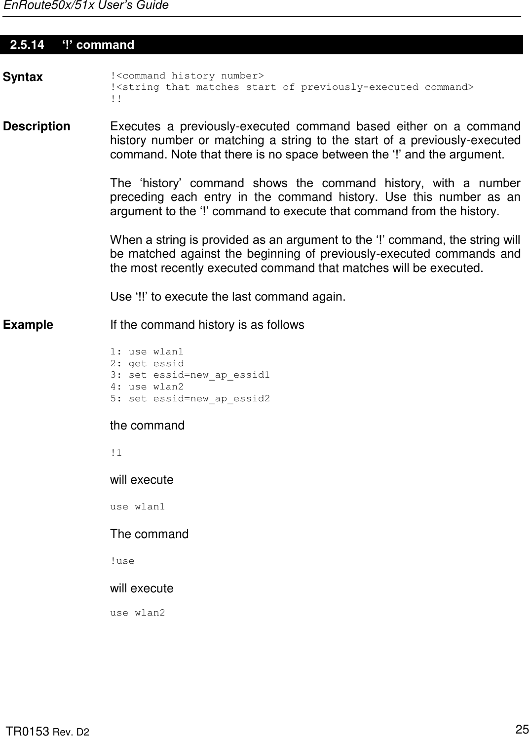
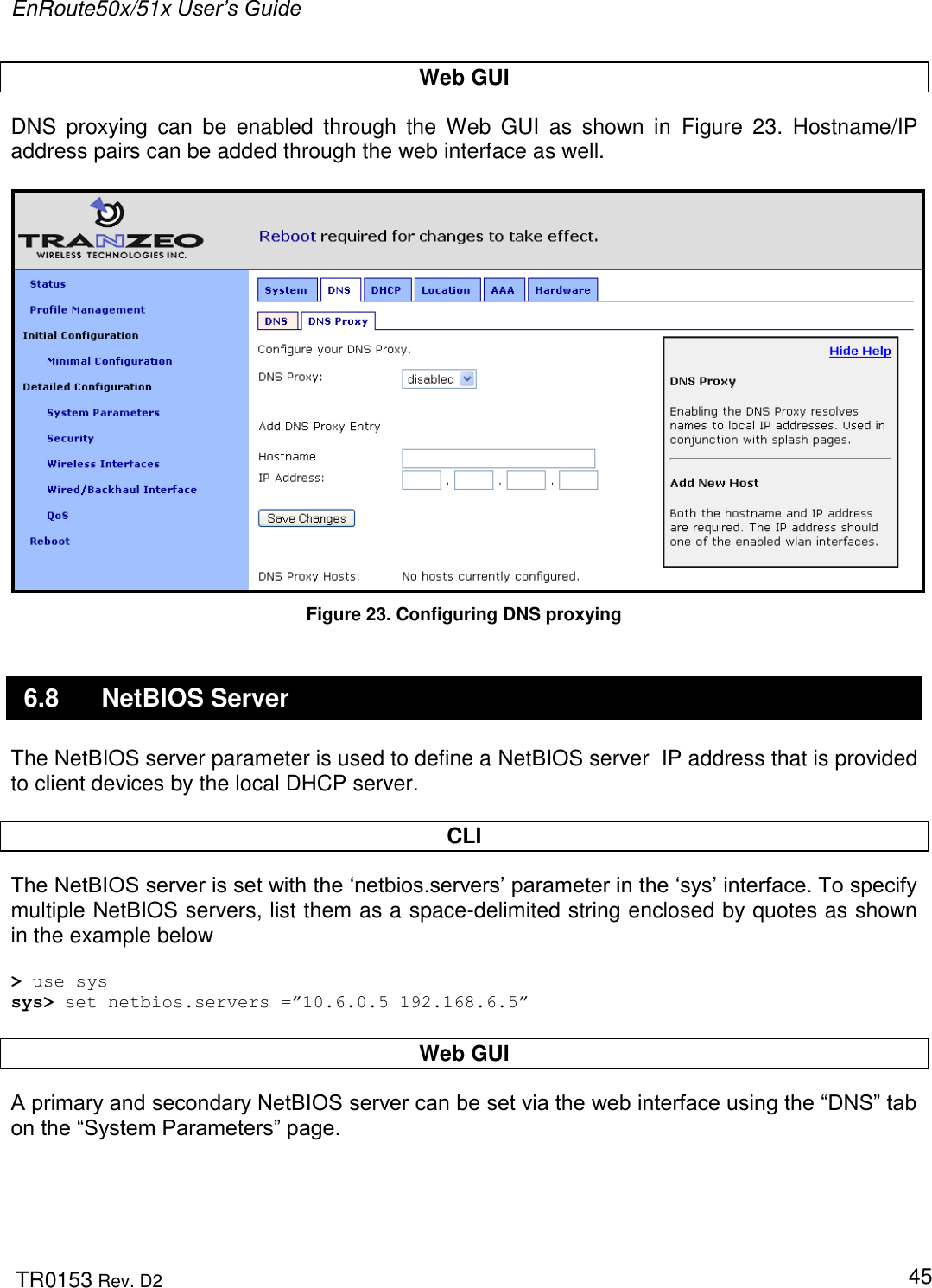
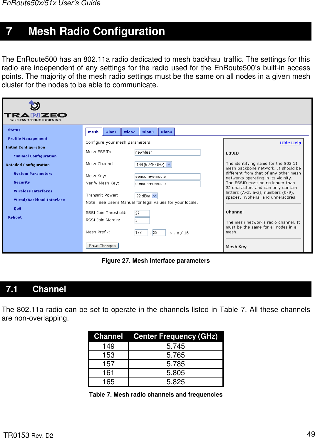
![EnRoute50x/51x User’s Guide TR0153 Rev. D2 18 2.5.3 ‘help’ command Syntax help [command|parameter] where [command] is one of the CLI commands or [parameter] is a parameter in the currently selected interface. Description When no argument follows the help command, a help menu showing a list of available commands is displayed. When a command is supplied as the argument, a help message for that particular command is displayed. When a parameter in the current interface is specified as the argument, help information for it is displayed. Example help get will display the help information for the „get‟ command. With the „sys‟ interface selected sys> help scheme displays help information about that „scheme‟ parameter, as shown below scheme : wireless node type 2.5.4 ‘show’ command Syntax show Description Displays all available interfaces. An interface in this list can be selected with the „use‟ command.](https://usermanual.wiki/Tranzeo-Wireless-Technologies/RAKT3KN2.USERS-MANUAL-1/User-Guide-797586-Page-18.png)
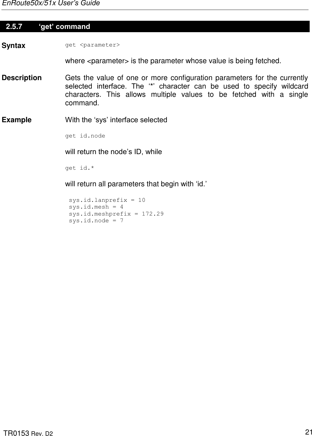
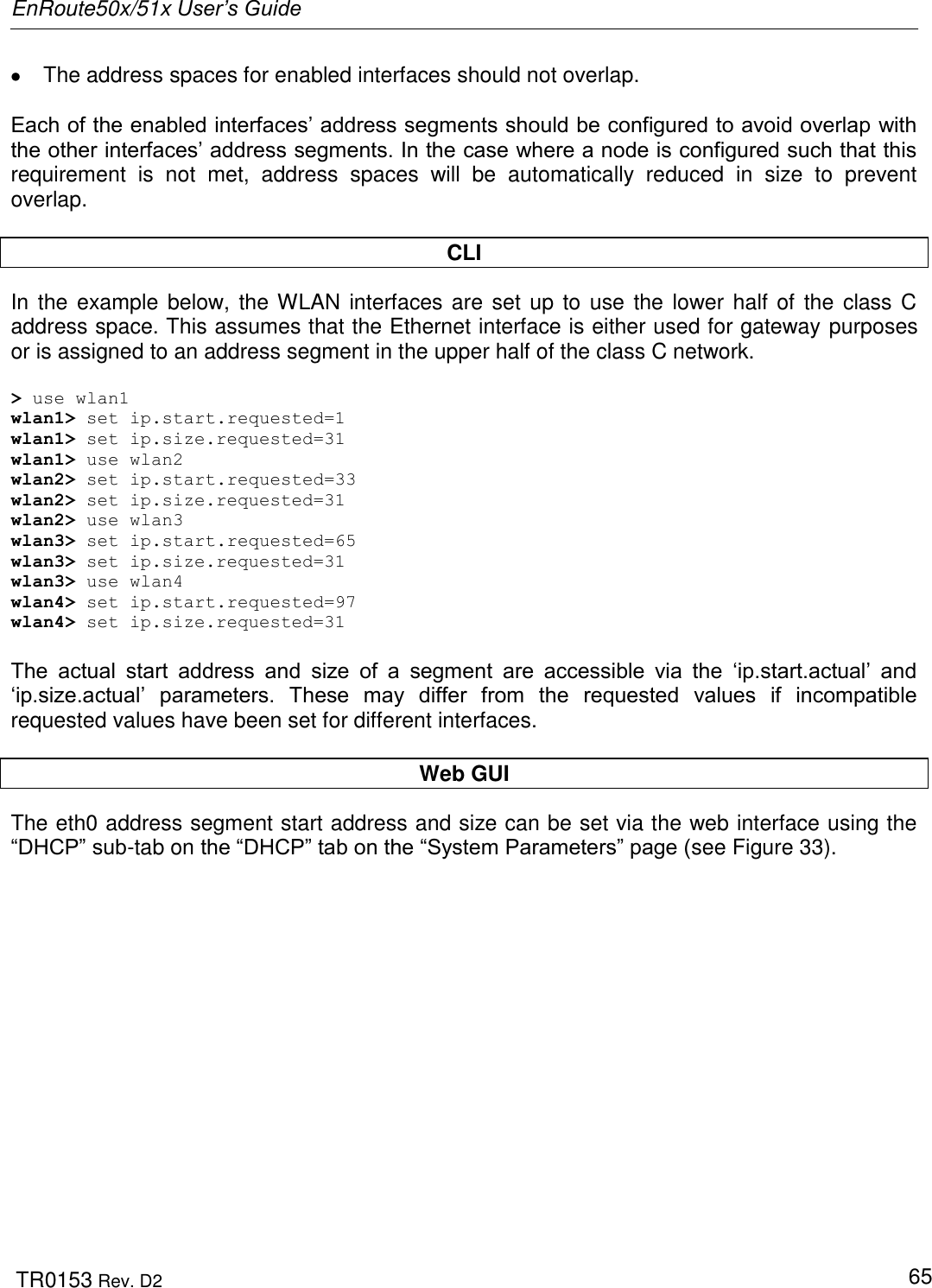
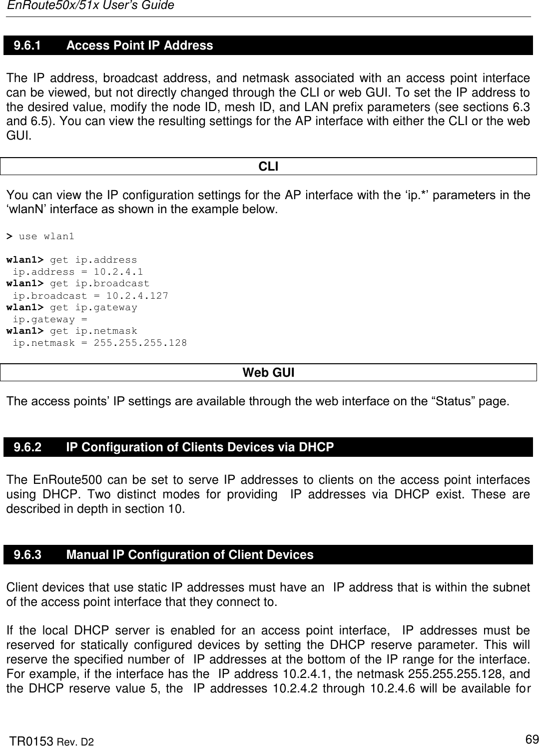
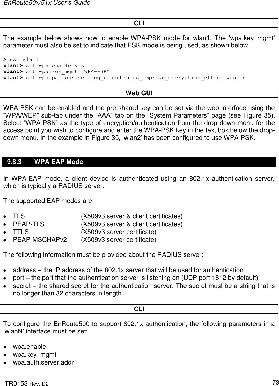
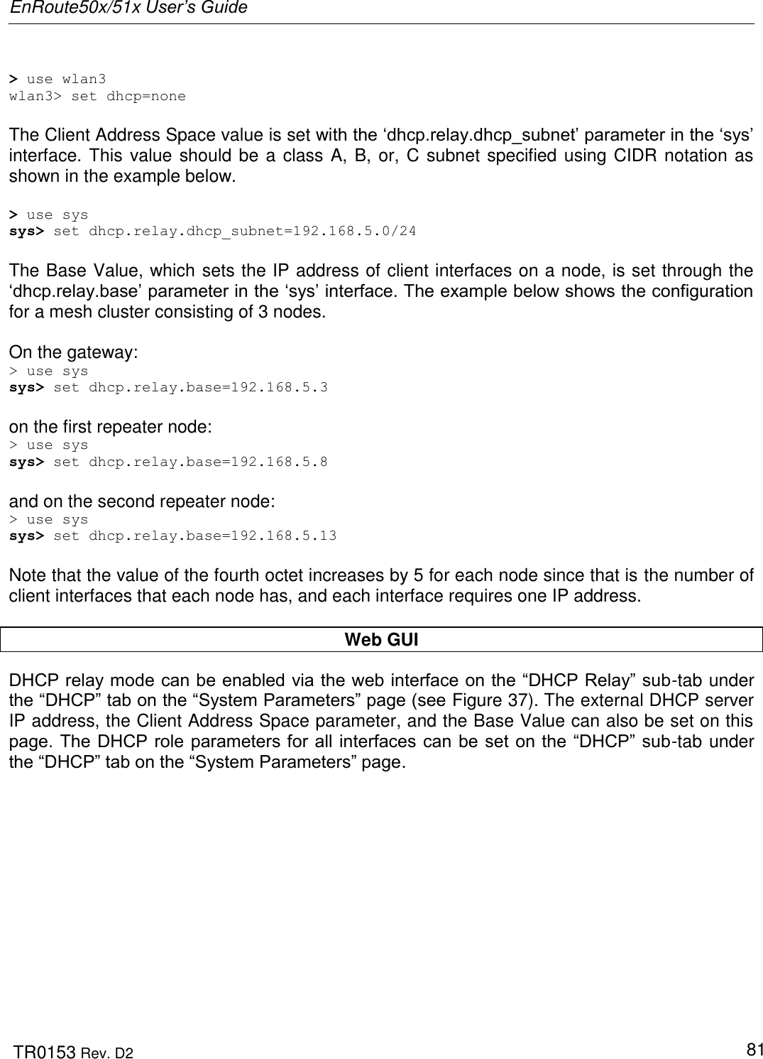
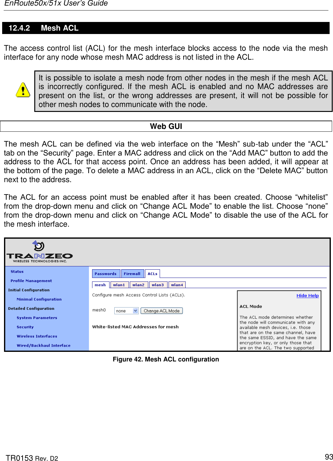
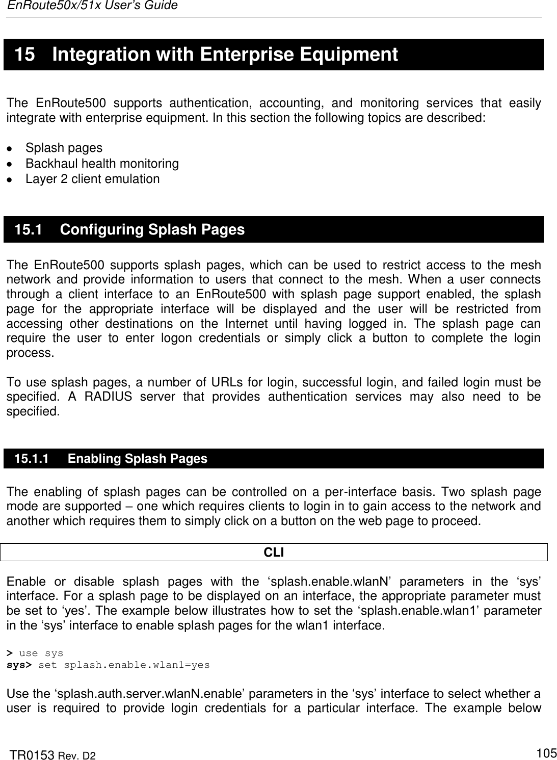
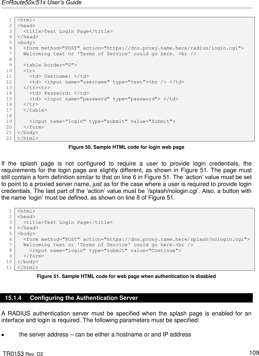
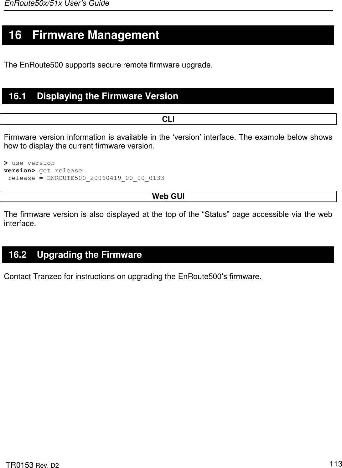
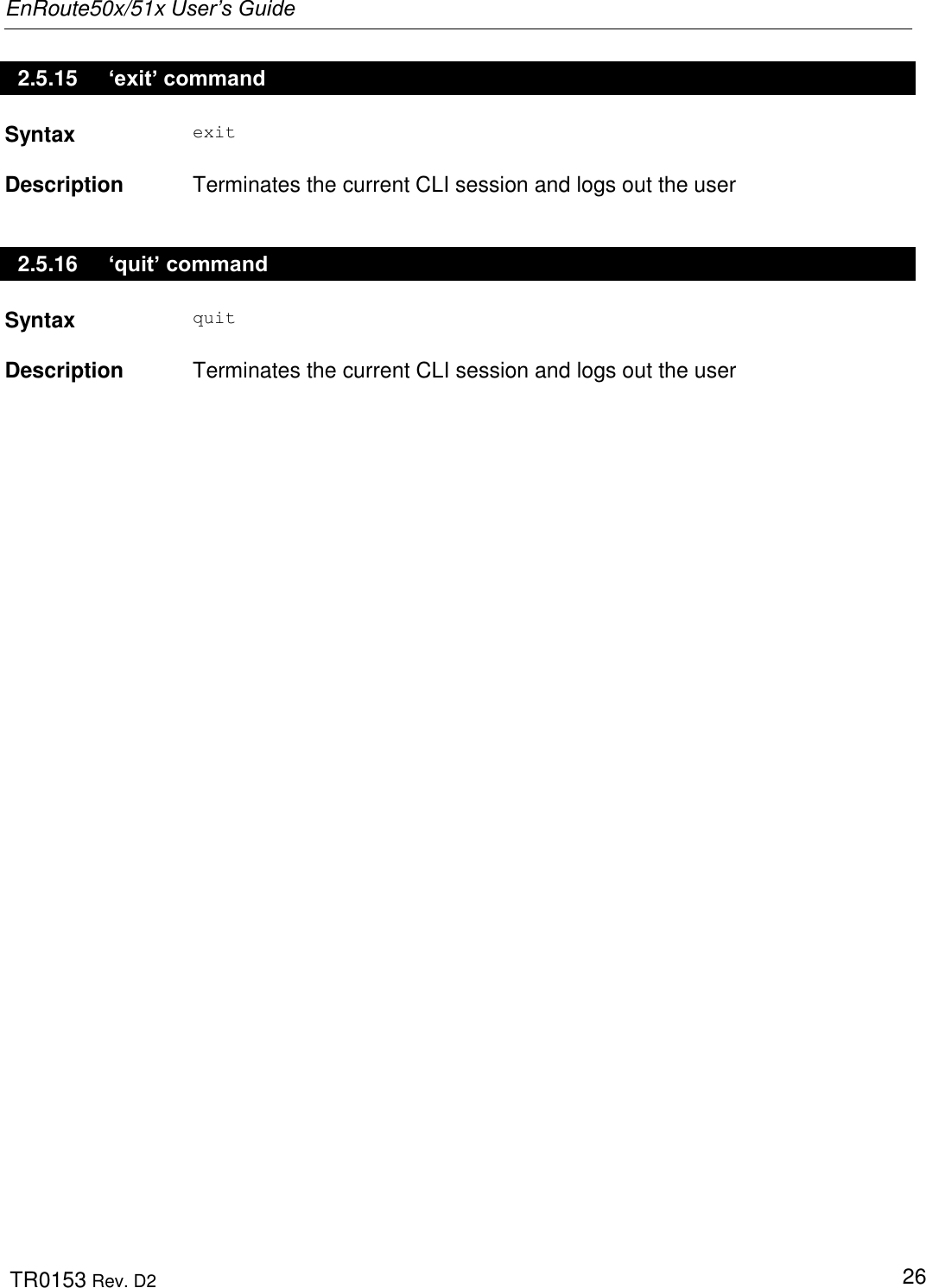
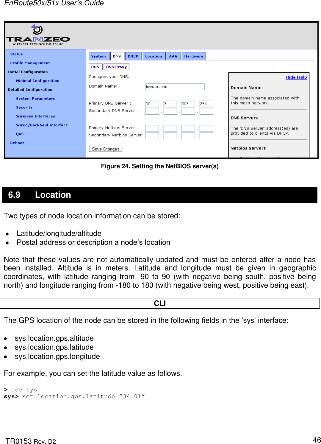
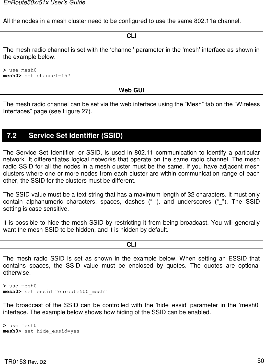
![EnRoute50x/51x User’s Guide TR0153 Rev. D2 23 2.5.10 ‘ifconfig’ command Syntax ifconfig <eth0|wlan[0-4]> Description Displays information, such as IP address and MAC address, for the specified network interface. Example ifconfig wlan1 will display wlan1 Link encap:Ethernet HWaddr 00:15:6D:52:01:FD inet addr:10.2.10.1 Bcast:172.29.255.255 Mask:255.255.0.0 UP BROADCAST RUNNING MULTICAST MTU:1500 Metric:1 RX packets:0 errors:0 dropped:0 overruns:0 frame:0 TX packets:2434 errors:0 dropped:0 overruns:0 carrier:0 collisions:0 txqueuelen:0 RX bytes:0 (0.0 b) TX bytes:233128 (227.6 Kb) 2.5.11 ‘route’ command Syntax route Description Displays the current route table. 2.5.12 ‘clear’ command Syntax clear Description Clears the screen](https://usermanual.wiki/Tranzeo-Wireless-Technologies/RAKT3KN2.USERS-MANUAL-1/User-Guide-797586-Page-23.png)
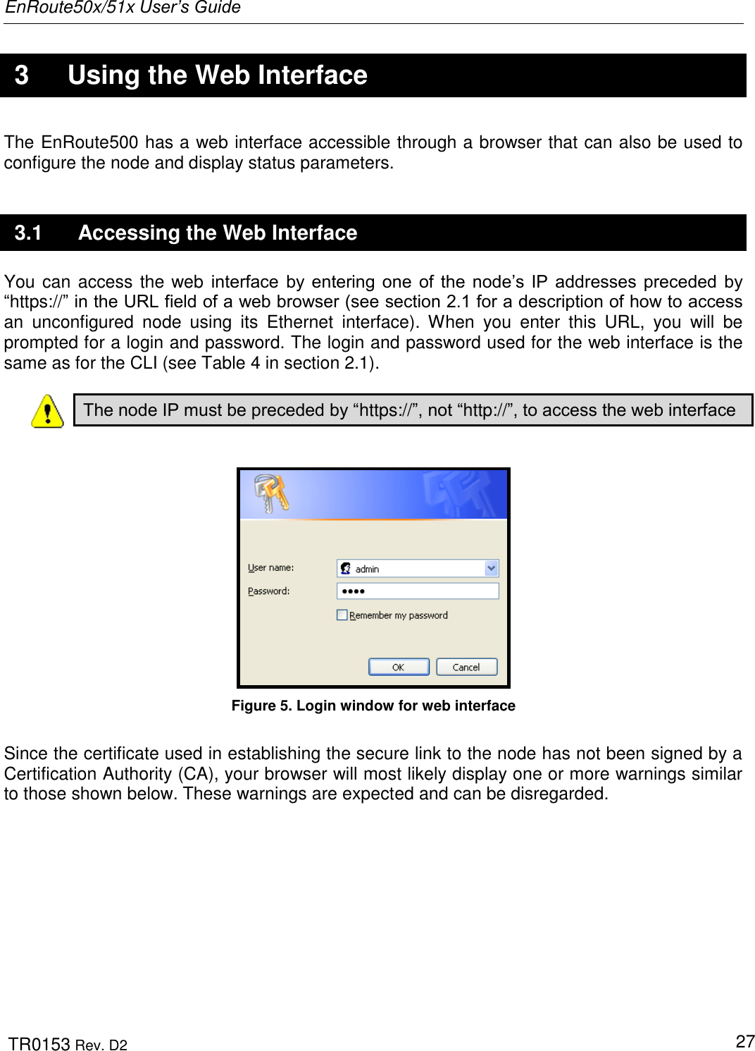
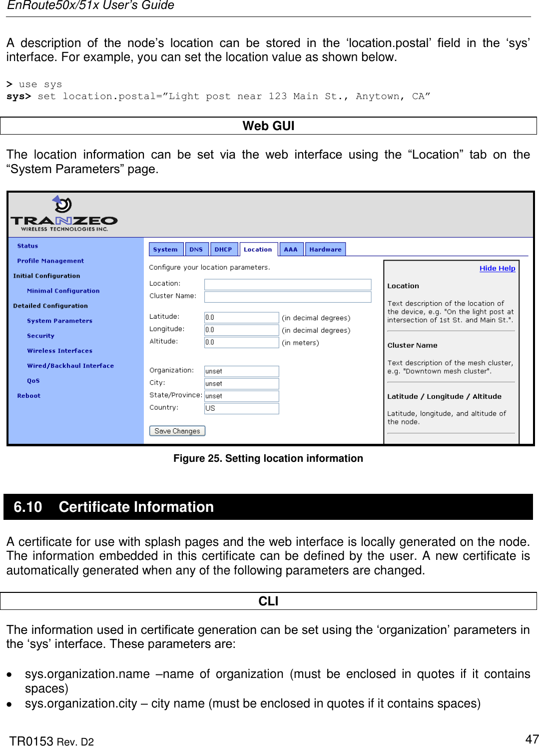
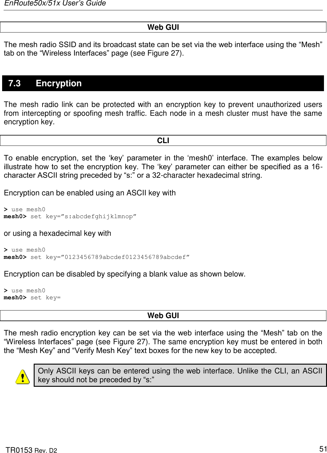
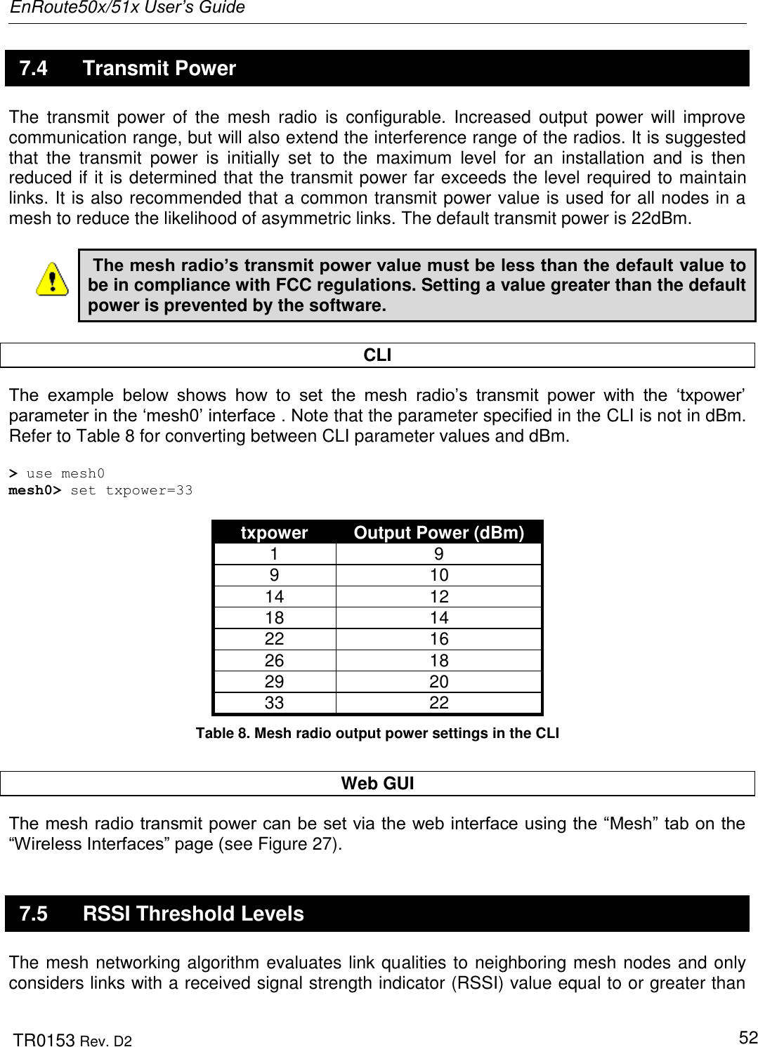
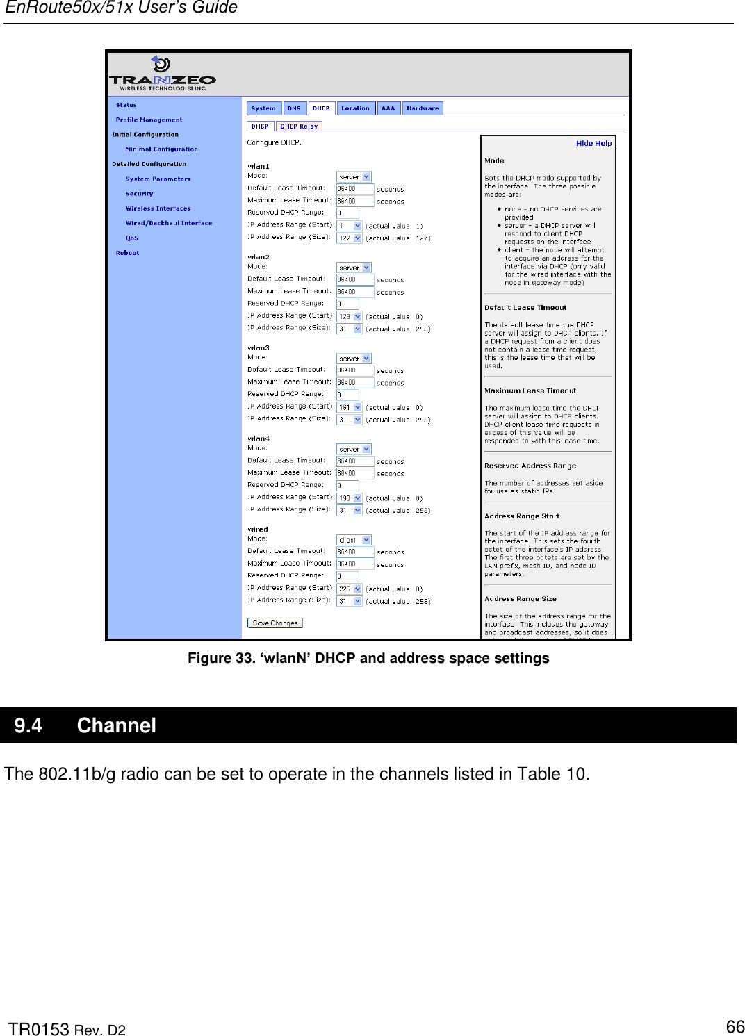
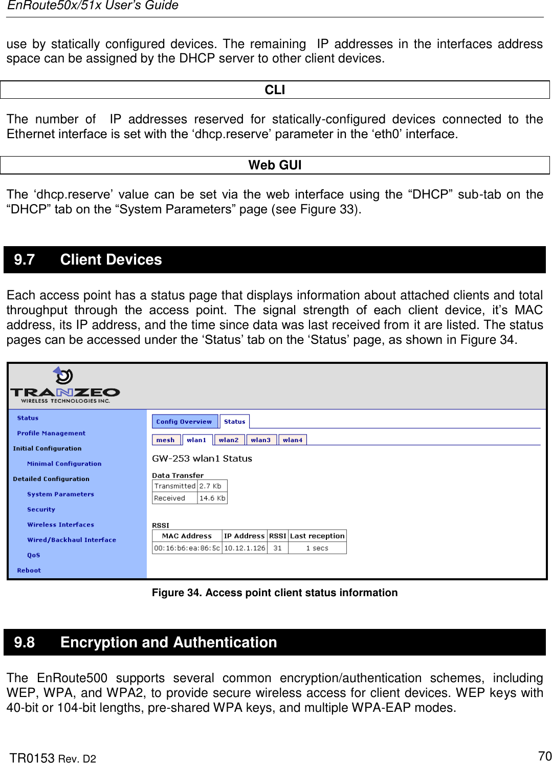
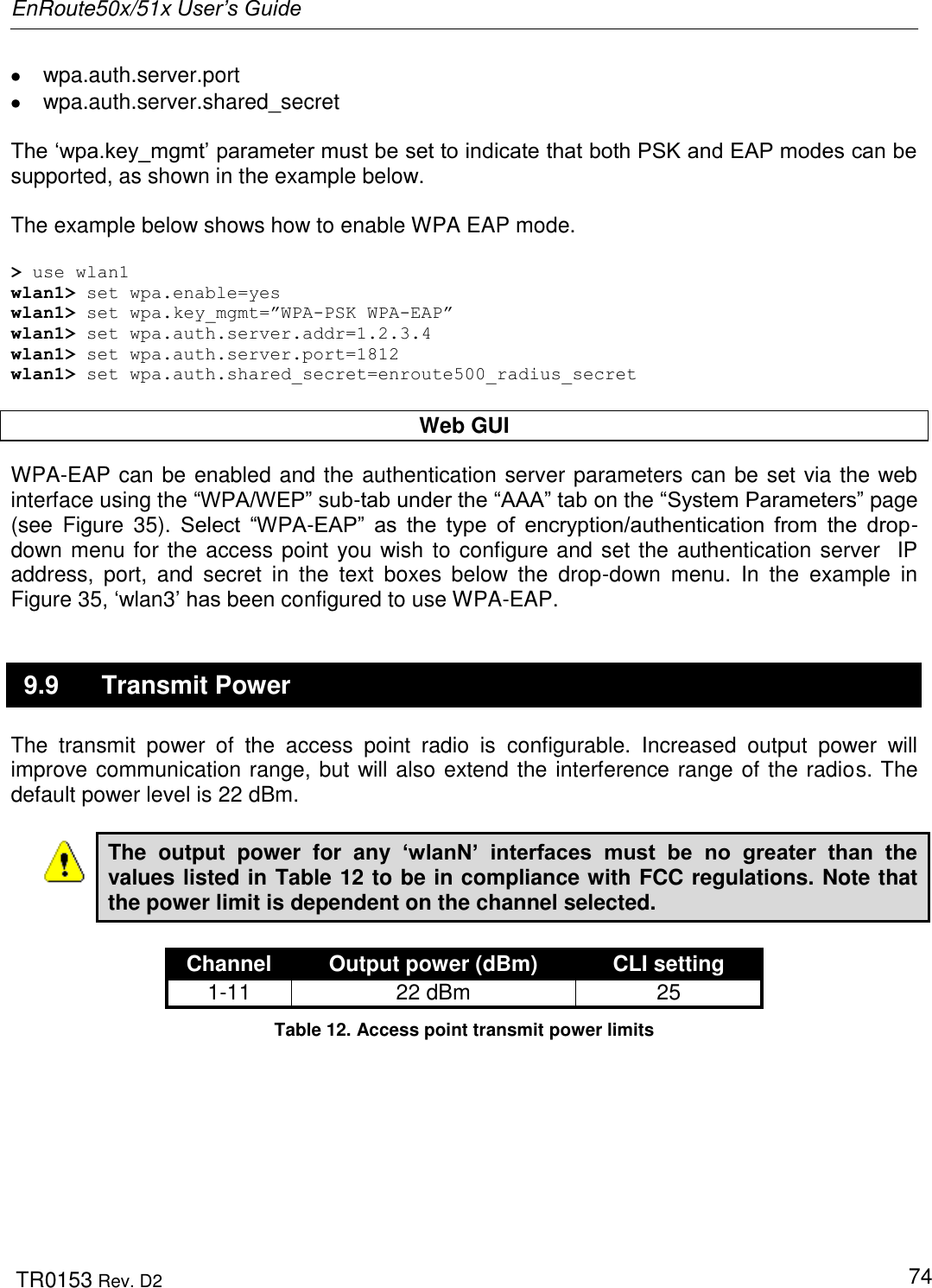
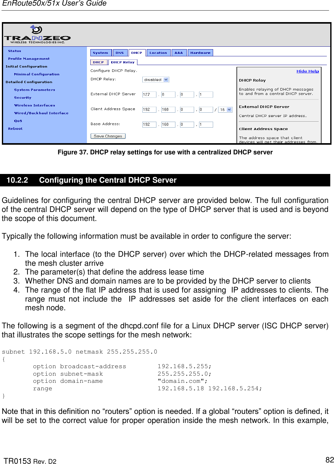
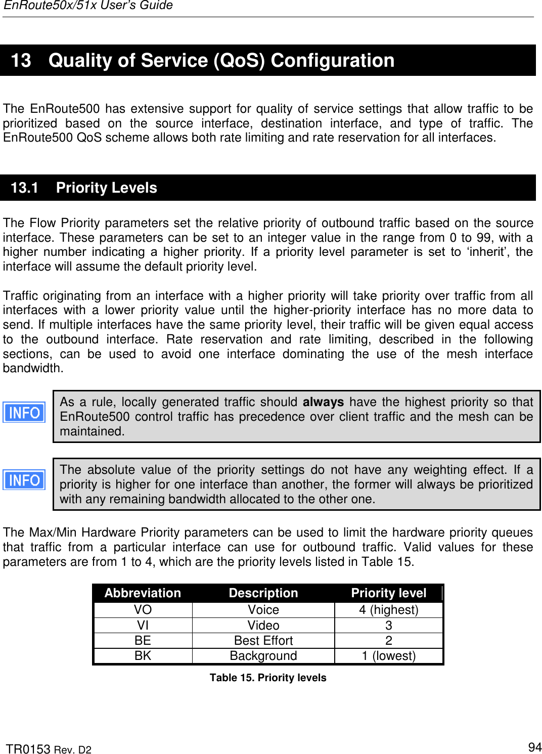
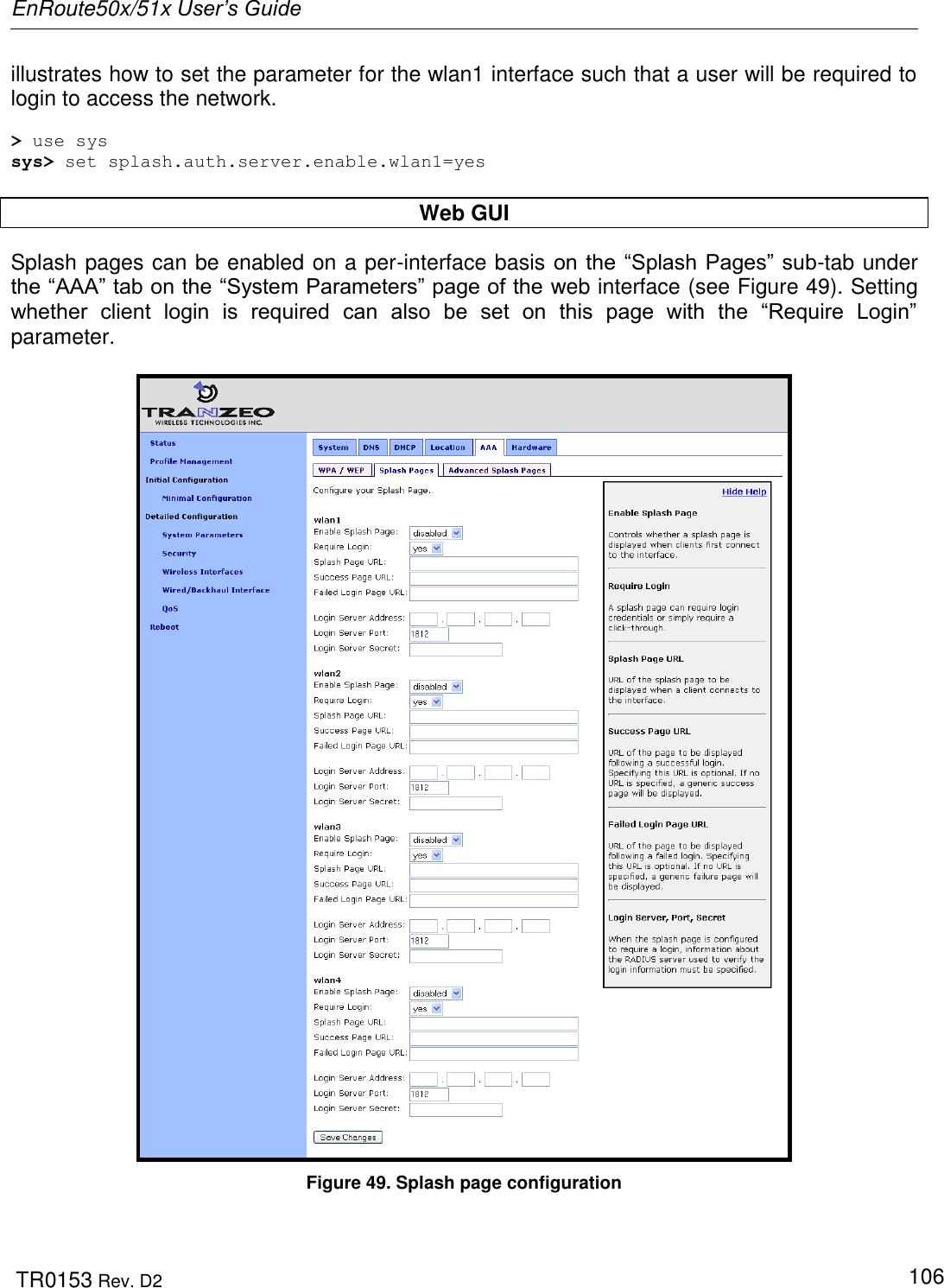
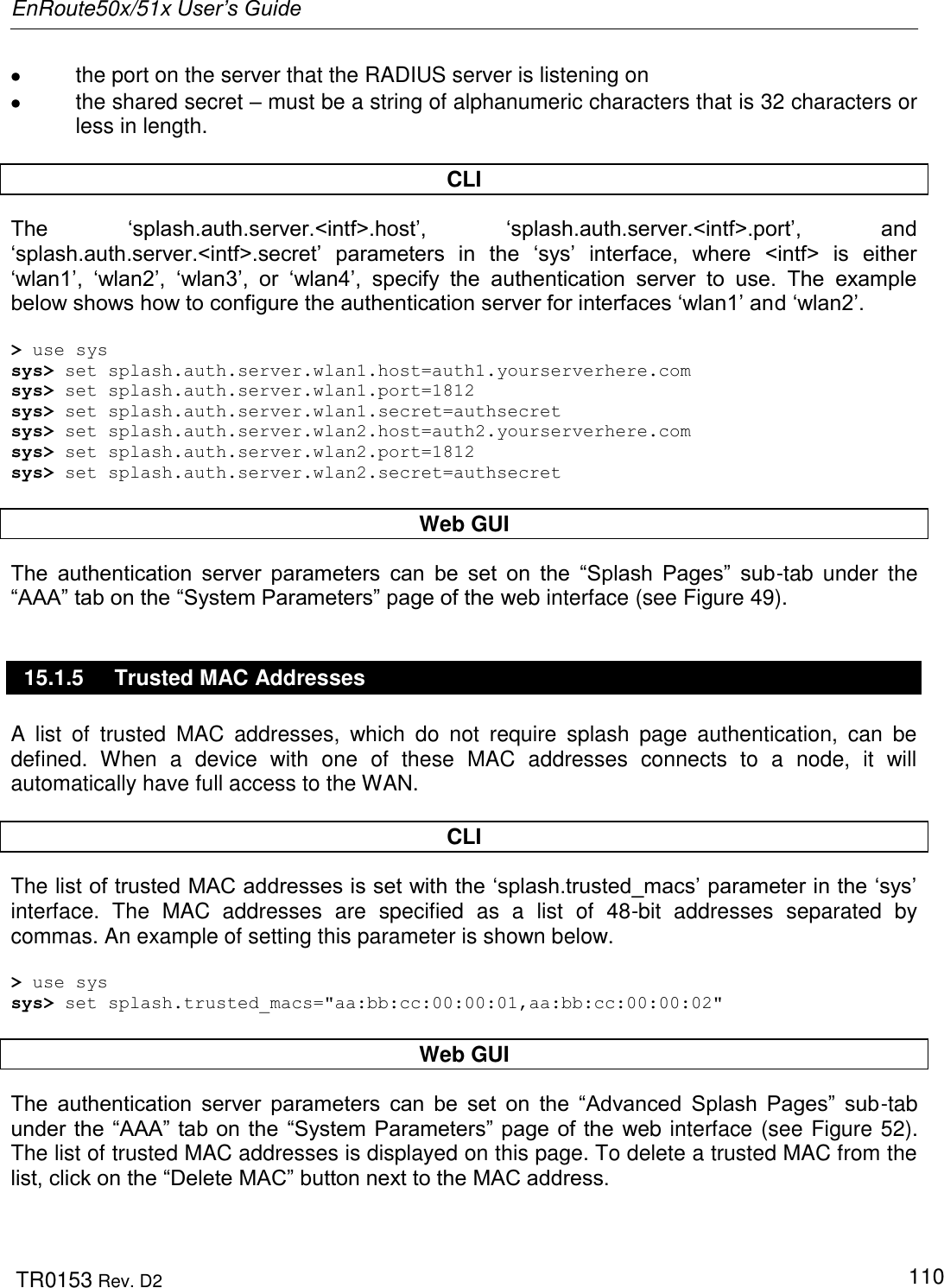
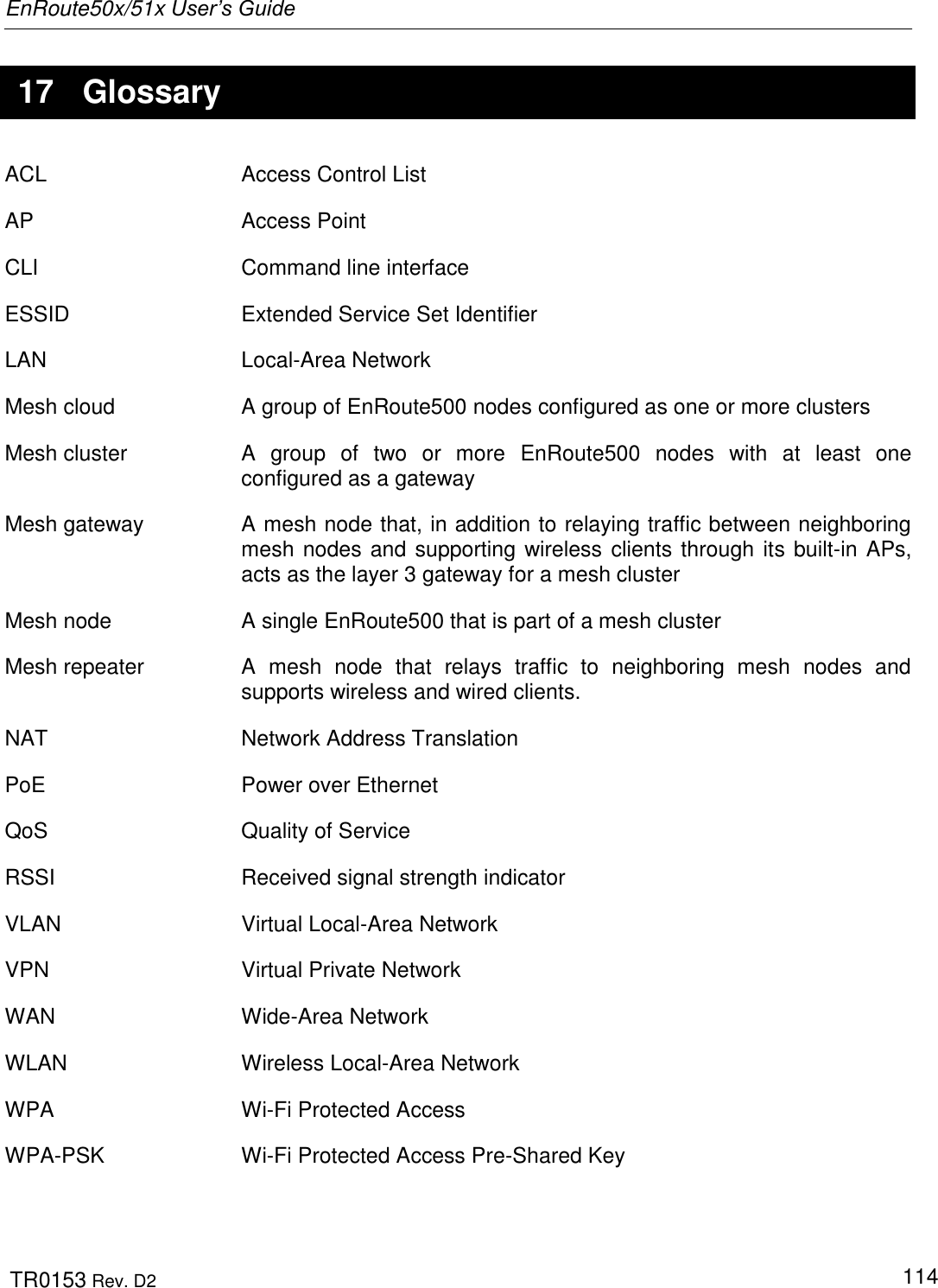
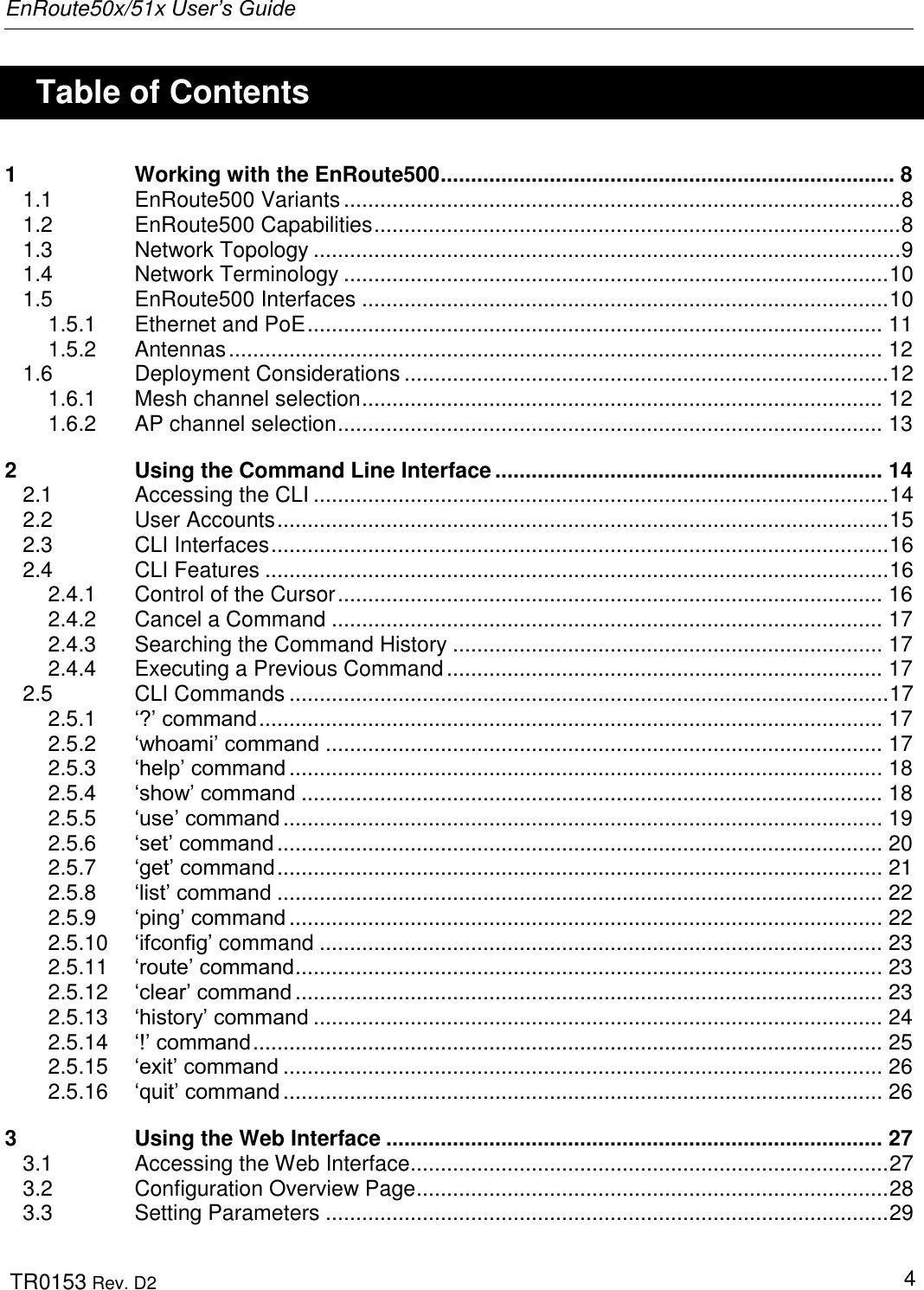
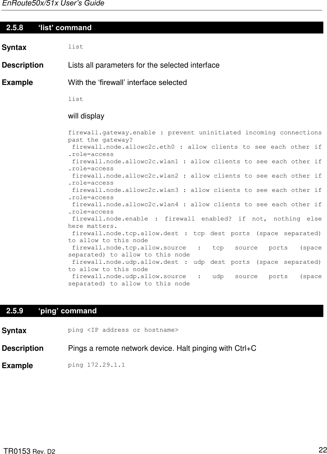
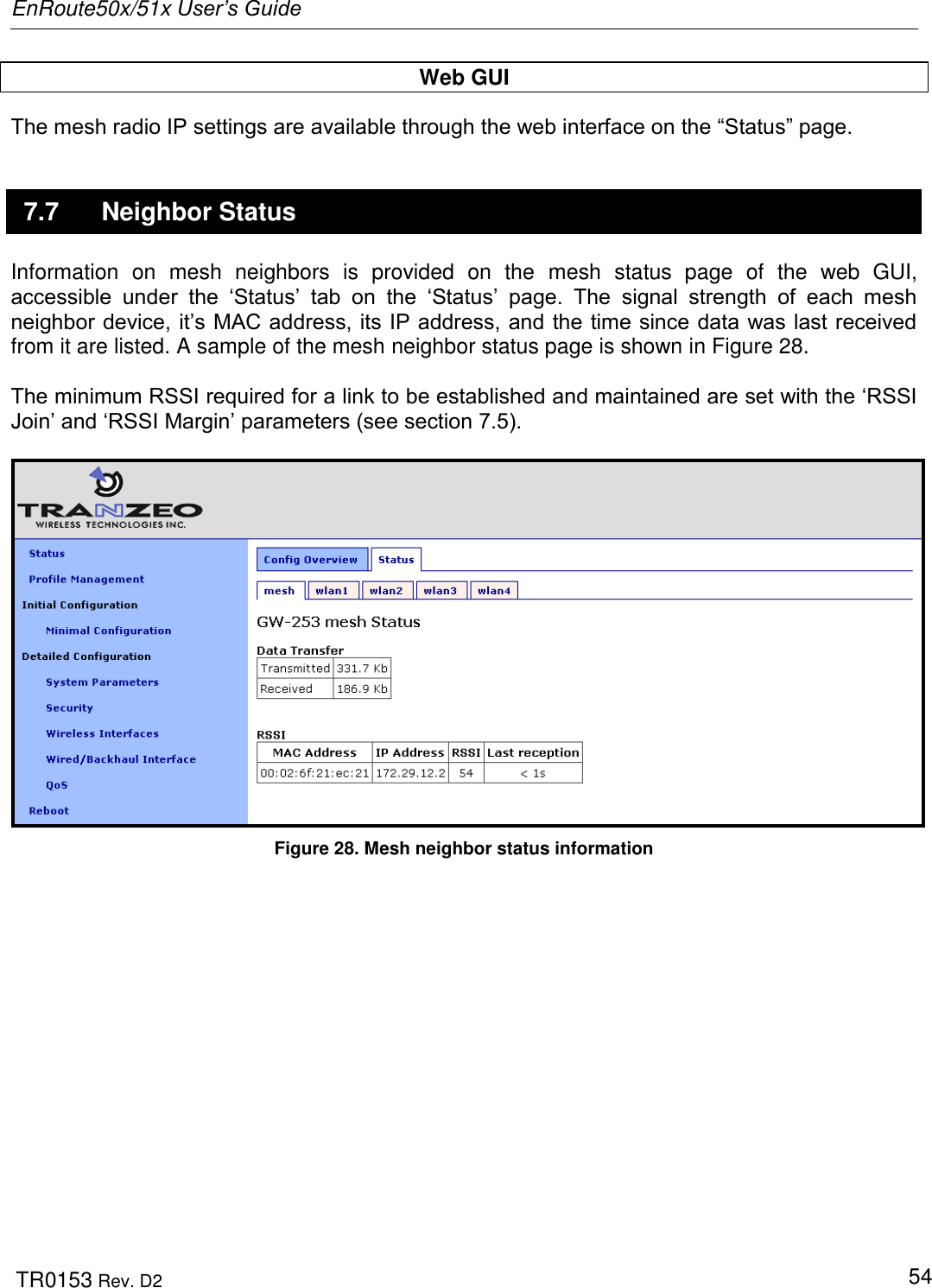
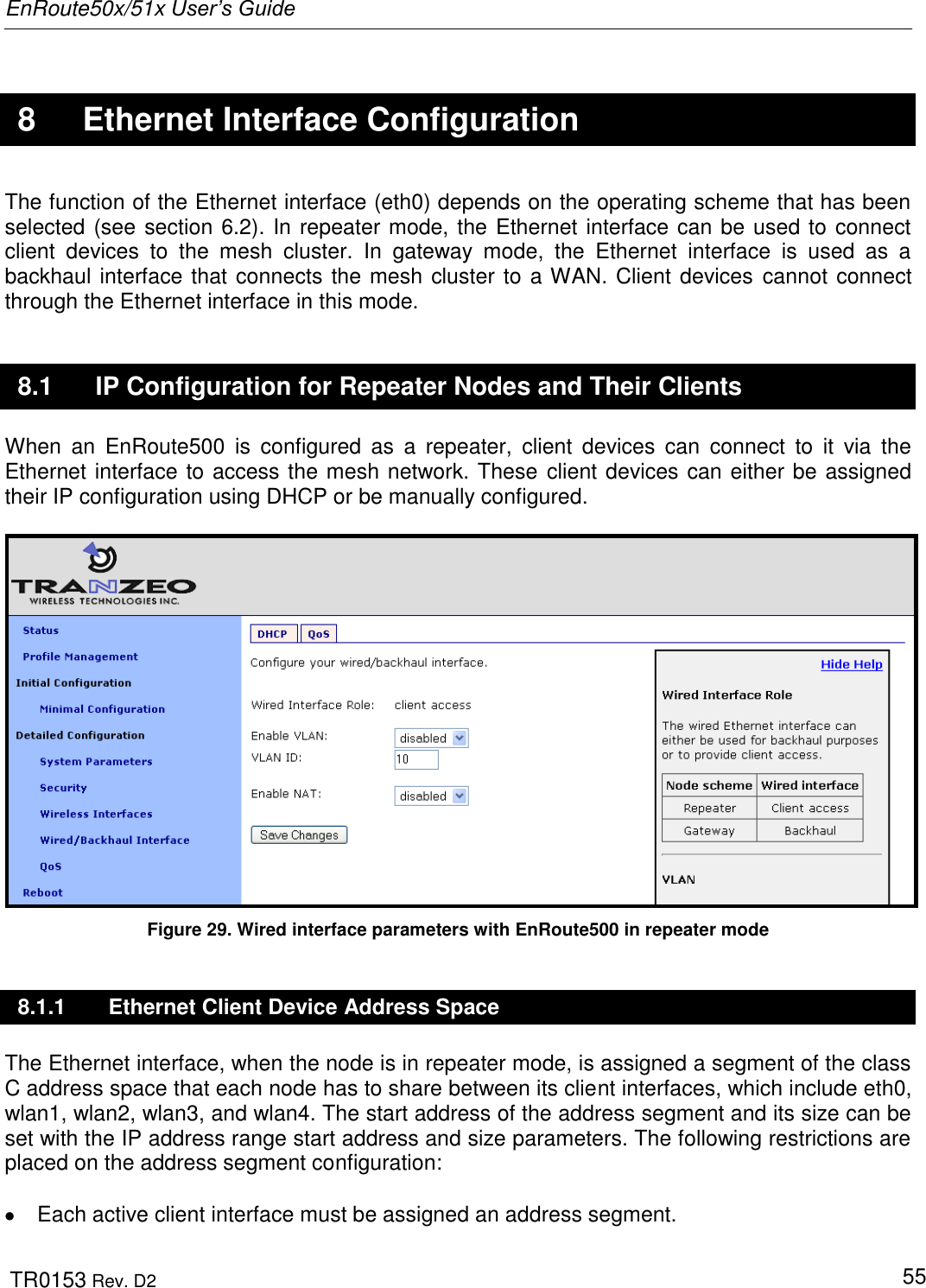
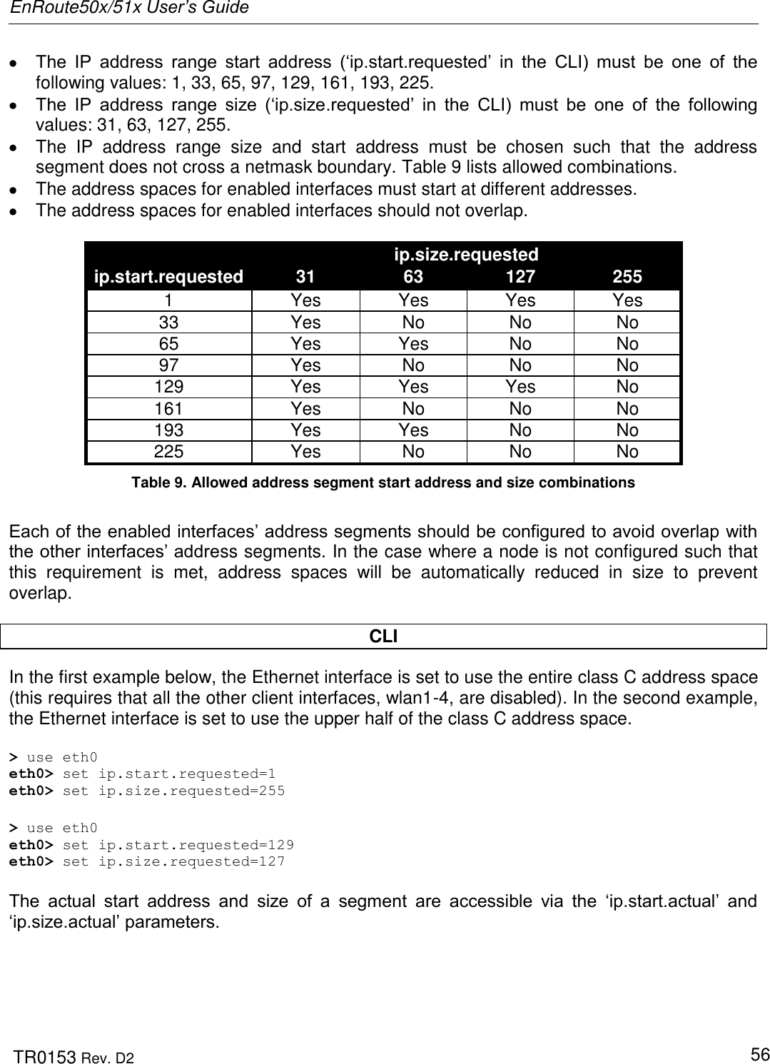
![EnRoute50x/51x User’s Guide TR0153 Rev. D2 53 the „RSSI Join‟ value specified to be usable. The „RSSI Join‟ value is set to 27 by default. This value reflects the lowest RSSI that will allow the mesh radio to operate at its highest data rate. It is possible to achieve longer link ranges, at the cost of reduced throughput, by reducing the „RSSI Join‟ value. In combination with the „RSSI Join‟ value, the „RSSI Margin‟ value is used to set the RSSI level at which links are dropped. A link will be considered broken when its RSSI drops below the „RSSI Join‟ level by the amount specified with „RSSI Margin‟. For example, with an „RSSI Join‟ value of 27 and an „RSSI Margin‟ value of 3, the link will be dropped if the RSSI goes below 24. CLI The example below shows how to set the mesh radio‟s RSSI thresholds with the „fabric.rssi.join‟ and „fabric.rssi.margin‟ parameters in the „mesh0‟ interface . > use mesh0 mesh0> set fabric.rssi.join=27 > use mesh0 mesh0> set fabric.rssi.margin=3 Web GUI The mesh radio RSSI thresholds can be set via the web interface using the “Mesh” tab on the “Wireless Interfaces” page (see Figure 27). 7.6 IP Configuration The IP address, broadcast address, and netmask associated with the mesh radio interface can be viewed through the CLI and the web GUI interfaces. It is not possible to directly set these values though. To change the mesh interface IP settings, the node and mesh ID settings must be changed (see sections 6.3 and 6.4). CLI In the CLI, the mesh IP settings can be viewed with > use mesh0 mesh0> get ip.address ip.address = 172.29.2.4 [read-only] mesh0> get ip.broadcast ip.broadcast = 172.29.255.255 [read-only] mesh0> get ip.gateway ip.gateway = [read-only] mesh0> get ip.netmask ip.netmask = 255.255.0.0 [read-only]](https://usermanual.wiki/Tranzeo-Wireless-Technologies/RAKT3KN2.USERS-MANUAL-1/User-Guide-797586-Page-53.png)
![EnRoute50x/51x User’s Guide TR0153 Rev. D2 58 8.1.2 Ethernet Interface IP Address The EnRoute500‟s Ethernet interface IP address should not be changed directly when it is in repeater mode. To set the IP address to the desired value, modify the node ID, mesh ID, and LAN prefix parameters (see sections 6.3 and 6.5). CLI You can view the IP settings for the Ethernet interface with the „ip.*‟ parameters in the „eth0‟ interface as shown in the example below. > use eth0 eth0> get ip.* ip.address = 10.2.4.225 [read-only] ip.address_force = ip.broadcast = 10.2.4.255 [read-only] ip.broadcast_force = ip.gateway = [read-only] ip.gateway_force = ip.netmask = 255.255.255.0 [read-only] ip.netmask_force = ip.size.actual = [read-only] ip.size.requested = 31 ip.start.actual = [read-only] ip.start.requested = 225 When the node is in repeater mode, the Ethernet IP settings can be changed by altering the „id.node‟, „id.mesh‟, and „id.lanprefix‟ parameters in the „sys‟ interface and the „ip.start.requested‟ parameter in the „eth0‟ interface Web GUI The Ethernet IP settings are available through the web interface on the “Status” page. The Ethernet IP settings can be changed by altering the node ID, mesh ID, and LAN prefix settings on the “System” parameters tab on the “System Parameters” page. 8.1.3 IP Configuration of Client Devices via DHCP When configured as a repeater, the EnRoute500 can be set to serve IP addresses to clients on the Ethernet interface using DHCP. Two distinct modes for providing IP addresses via DHCP exist. These are described in depth in section 10.](https://usermanual.wiki/Tranzeo-Wireless-Technologies/RAKT3KN2.USERS-MANUAL-1/User-Guide-797586-Page-58.png)