TriGem Computer BLACKCRYSTAL Slim PC with WLAN 802.11 a/b/g User Manual Averatec Black Crystal User s G
TriGem Computer, Inc Slim PC with WLAN 802.11 a/b/g Averatec Black Crystal User s G
UserManual.wiki
>
TriGem Computer
>
BLACKCRYSTAL User Manual
User manual
Navigation menu
Upload a User Manual
Namespaces
Wiki Guide
HTML
PDF
Info
Views
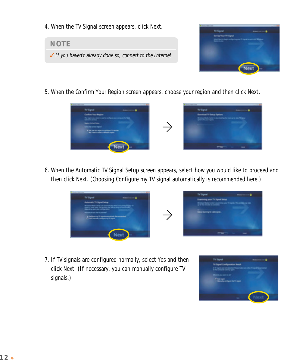
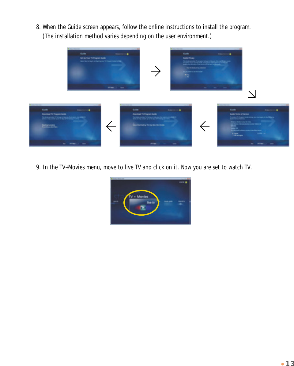
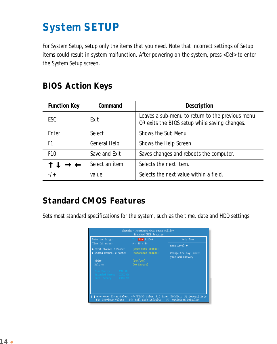
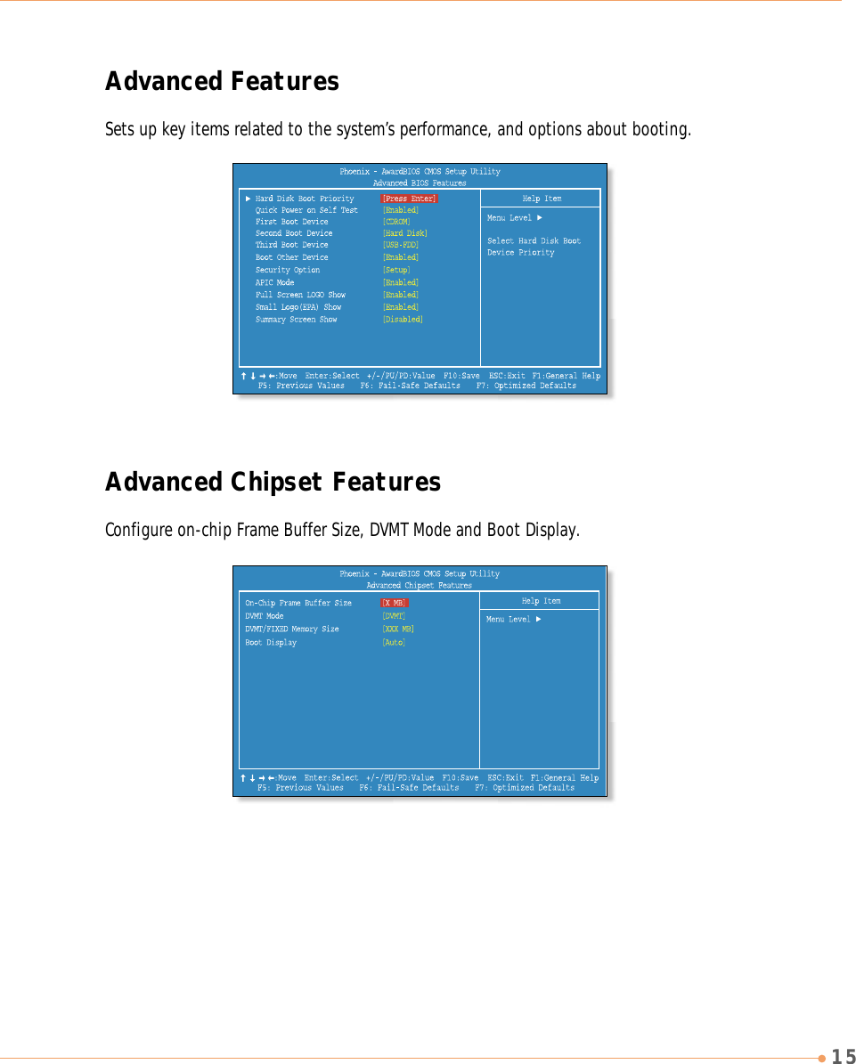
User Manual
Discussion / Help
Navigation

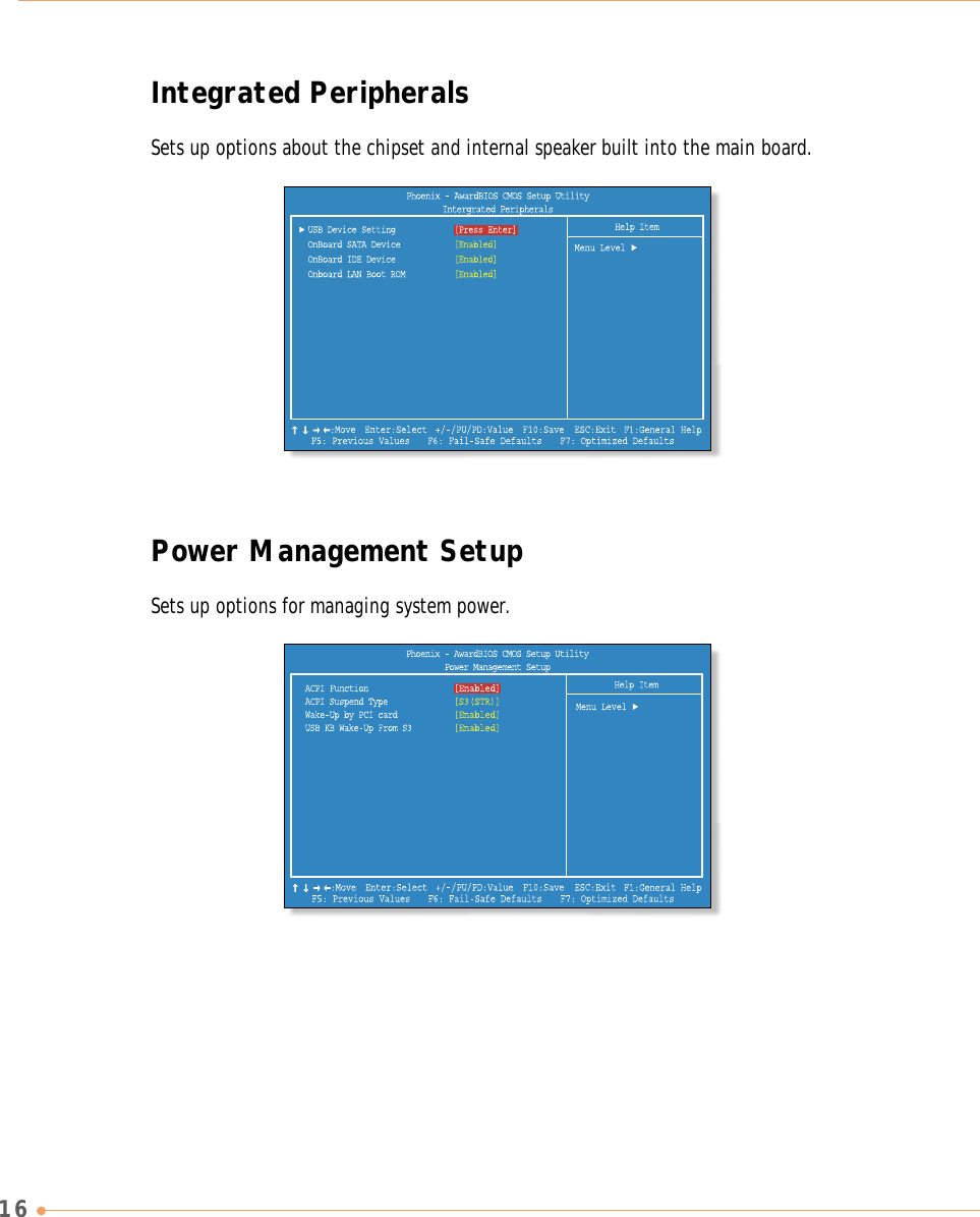
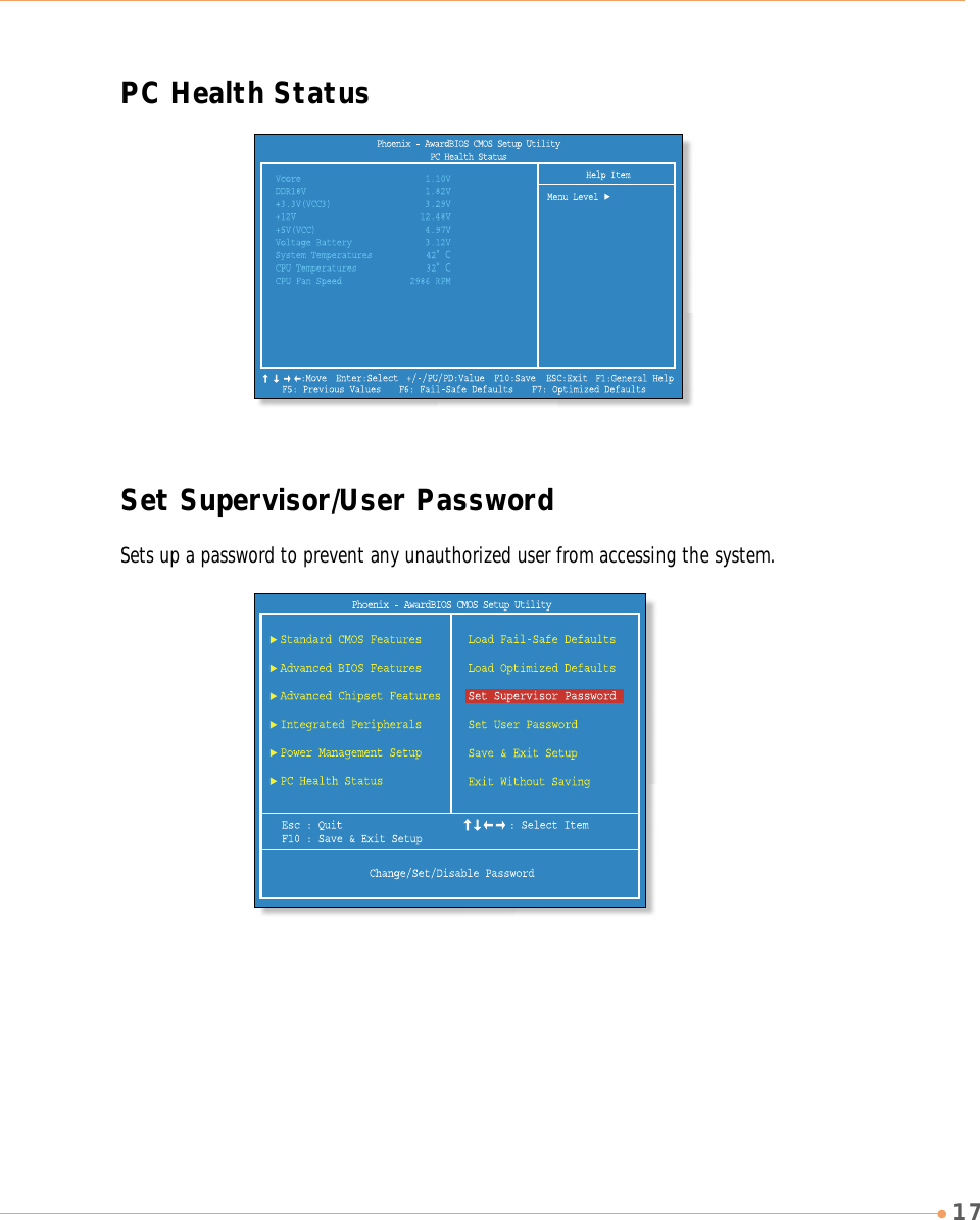
![18The Supervisor Password is at a higher level than the User Password.Changing a passwordYou can change a password with the same way as “Setting a password.”Deleting a passwordTo delete a password, follow these steps:1. Move to the Set Supervisor/User Password menu and press <Enter>.2. On the following screen, press <Enter> without any input.3. On the following screen, press <Enter>.1. On the initial System Setup screen, press < / > to go to the Set Supervisor/User Password menu and then press<Enter>.Setting a password2. On the following screen, enter the password and thenpress <Enter>.3. If you entered the correct password, the followingwindow will appear. Press <Enter>.Then enter the same password again and press <Enter>.This completes setting up a password.Enter PasswordConfirm PasswordPassword installed[OK]Enter Password](https://usermanual.wiki/TriGem-Computer/BLACKCRYSTAL/User-Guide-965169-Page-27.png)