TriGem Computer BLACKCRYSTAL Slim PC with WLAN 802.11 a/b/g User Manual Averatec Black Crystal User s G
TriGem Computer, Inc Slim PC with WLAN 802.11 a/b/g Averatec Black Crystal User s G
User manual

TM
User’s Guide
PC

i
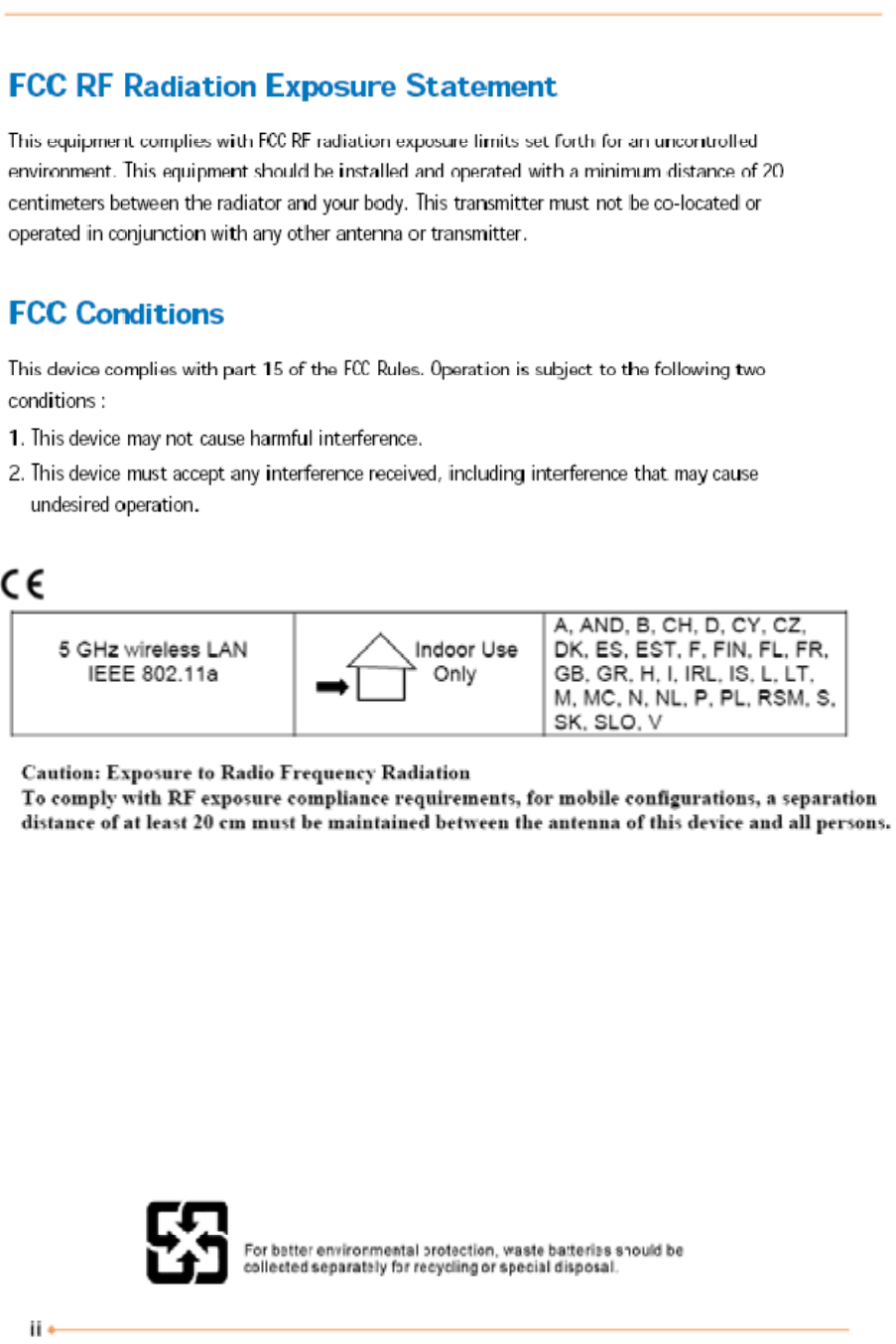
Regulations Information
FCC-B Radio Frequency Interference Statement
This equipment has been tested and found to comply with the limits for a Class B digital device,
pursuant to part 15 of the FCC rules. These limits are designed to provide reasonable protection
against harmful interference in a residential installation. This equipment generates, uses and can
radiate radio frequency energy and, if not installed and used in accordance with the instructions,
may cause harmful interference to radio communications. However, there is no guarantee that
interference will not occur in a particular installation. If this equipment does cause harmful
interference to radio or television reception, which can be determined by turning the equipment
off and on, the user is encouraged to try to correct the interference by one or more of the
following measures :
✓Reorient or relocate the receiving antenna.
✓Increase the separation between the equipment and receiver.
✓Connect the equipment into an outlet on a circuit different from that to which the receiver is
connected.
✓Consult the dealer or an experienced radio TV technician for help.
NOTE
✓The changes or modifications not expressly approved by the party responsible for compliance could
void the user’s authority to operate the equipment.
✓Shield interface cables and AC power cord, if any must be used in order to comply with the emission
limits.

iii
Macrovision Notice
This product incorporates copyright protection technology that is protected by U.S. patents and
other intellectual property rights. Use of this copyright protection technology must be
authorized by Macrovision, and is intended for home and other limited viewing uses only unless
otherwise authorized by Macrovision. Reverse engineering or disassembly is prohibited.
Optical Device Drive Notice
CAUTION
✓This appliance contains a laser system and is classified as a “CLASS 1 LASER PRODUCT.” To use this
model properly, read the instruction manual carefully and keep this manual for your future reference.
In case of any trouble with this model, please contact your nearest “AUTHORIZED service station.” To
prevent direct exposure to the laser beam, do not try to open the enclosure.

iv
Safety Instructions
1. Read the safety instructions carefully and thoroughly.
2. Save this User Guide for possible use later.
3. Keep this equipment away from humidity and high temperature.
4. Lay this equipment on a stable surface before setting it up.
5. The openings on the enclosure are used for air convection and to prevent the equipment from
overheating. Do not cover the openings.
6. Make sure that the power voltage is within its safety range and has been adjusted properly to
the value of 100-240V before connecting the equipment to the power inlet.
7. Place the power cord in a way that people are unlikely to step on it. Do not place anything on
the power cord.
8. Always unplug the power cord before inserting any add-on card or module.
9. All cautions and warnings on the equipment should be noted.
10. If any of the following situations arises, get the equipment checked by a service personnel:
✓The power cord or plug is damaged.
✓Liquid has penetrated into the equipment.
✓The equipment has been exposed to moisture.
✓The equipment has not worked well or you can not get it work according to Users Manual.
✓The equipment was dropped and damaged.
✓The equipment has obvious signs of breakage.
11. Never pour any liquid into the opening that could damage the equipment or cause an
electrical shock.
12. Do not leave the equipment in an unconditioned environment with a storage temperature of
60°C (140°F) or above, which may damage the equipment.
13. CAUTION : To prevent explosion caused by improper battery replacement, use the same or
equivalent type of battery recommended by the manufacturer only.
14. This equipment is indoor use and all the communication wirings are limited to inside of the
building.
v
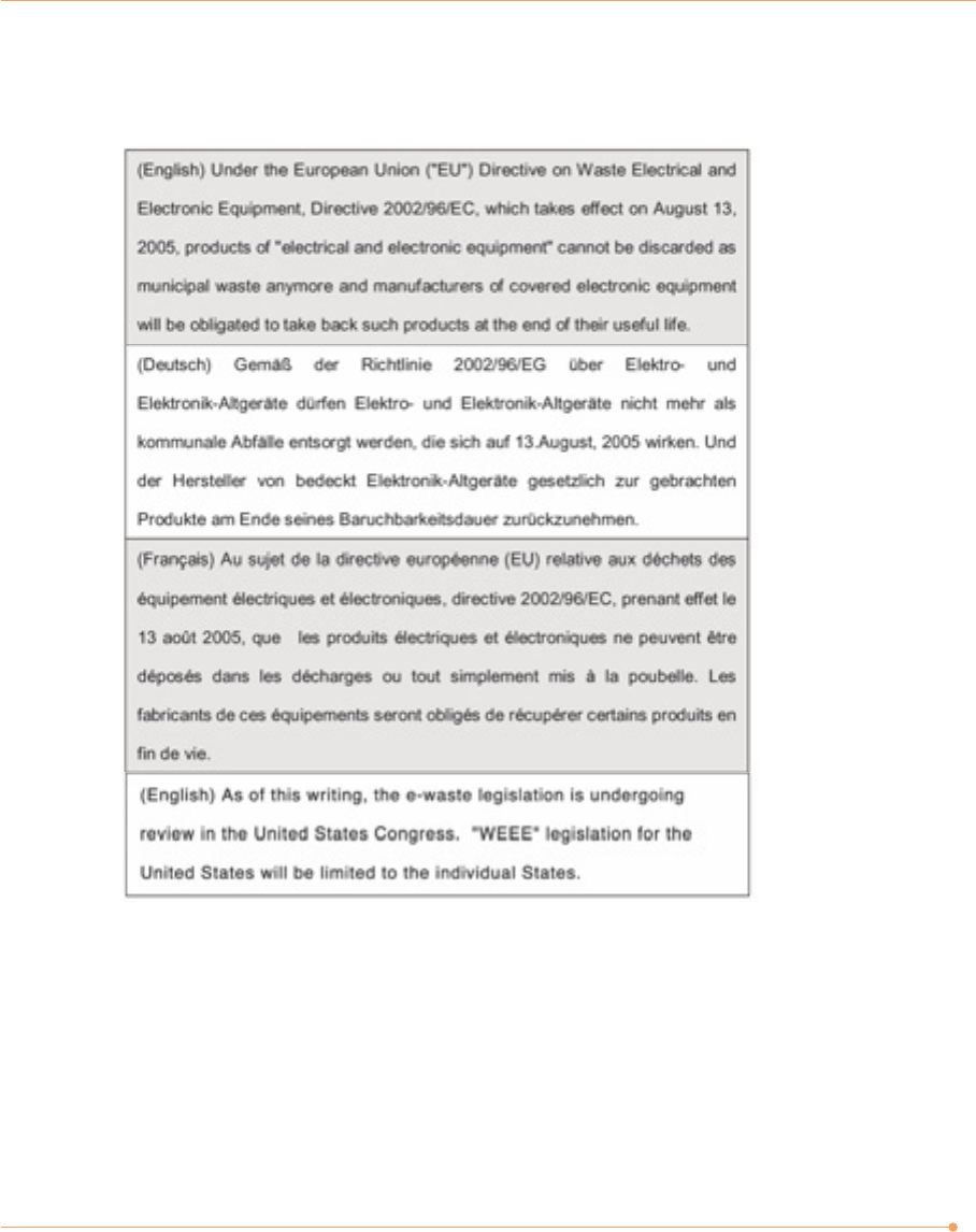
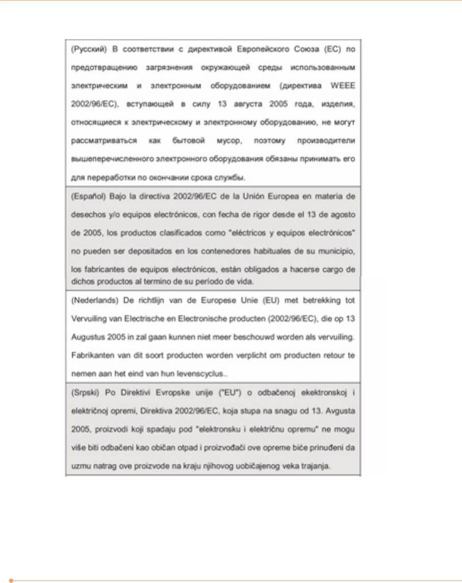
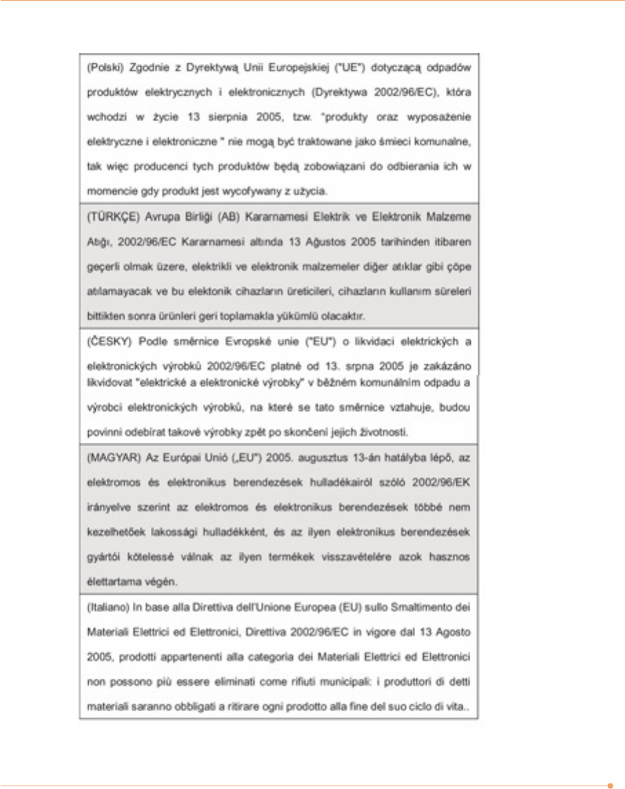
WEEE Statement
vi
vii

viii
Table of Content
Regulations Information i
Optical Device Drive Notice iii
Macrovision Notice iii
Safety Instructions iv
WEEE Statement v
System Overview 1
Turnning On and Off the Computer 2
Using the Optical Drive 3
Connect to the Internet 5
Using the Multi-Card Reader 6
Using the Wireless LAN 7
Connecting the TV 9
Watching TV 11
System SETUP 14
Expanding the Main Memory 19
Replacing the Hard Disk Drive 24
Replacing the CD Drive 28
Installing the Optional MXM Video Card 30
1
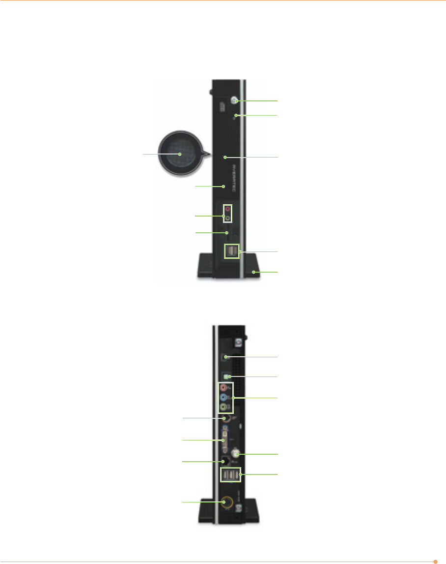
System Overview
Front
Rear
Power button/Power LED
HDD/CD drive LED
USB connector
SPDIF jack
Microphone/LINE IN/LINE OUT jack
TV antenna connector (optional)
IEEE 1394 connector
Stand
CD/DVD eject button
CD drive
(CD-RW/COMBO/DVD-Recorder)
Air vent hole
Microphone/Headphone jack
Card reader slot
Video-out connector
DVI-I connector
LAN connector
Power connector
USB connector

Turning On and Off the Computer
Turning on the computer
To turn on your computer, follow these steps:
1. Connect the peripheral devices and power cord to your computer. For more information, see
the Quick Start Guide.
2. Turn on any peripheral devices, such as printers or scanners.
3. Press the power button on the front panel of your computer.
4. If you are starting your computer for the first time, follow the on-screen instructions to set
up your computer. For more information, see the Quick Start Guide.
Turning off the computer
To turn off your computer, follow these steps:
1. Before turning off your computer, save your information and close all application programs
you use.
2. Click the Start button, then click Turn Off Computer. The Turn Off Computer dialog box
appears.
3. Click Turn Off to shut down the computer.
4. Turn off the monitor and any other peripheral devices.
2
NOTE
✓If for some reason you cannot turn off your computer in Windows, press and hold the power button
for about three to five seconds to turn off your computer.
3
1
2
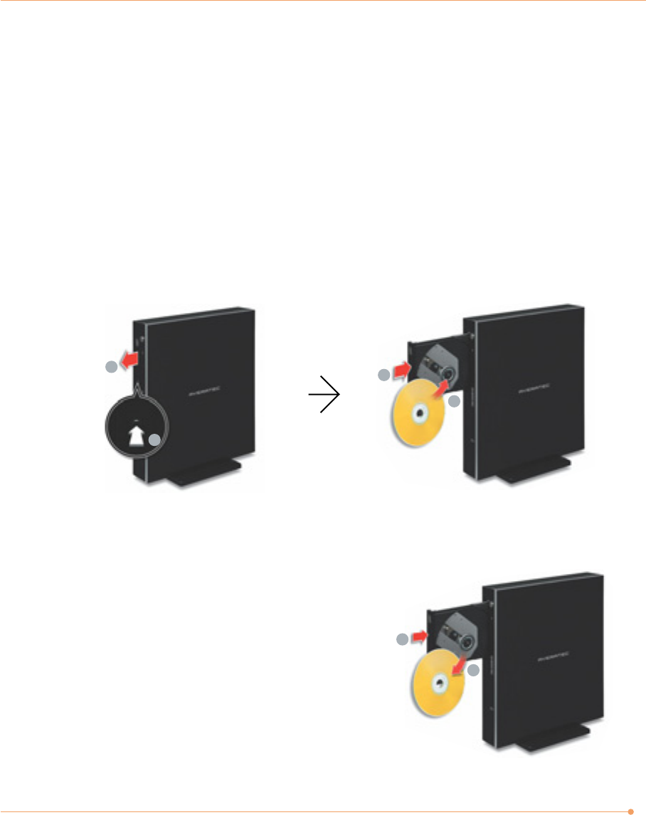
Using the Optical Drive
The AVERATEC Black Crystal PC is fitted with a slim tray-loading optical drive.
1
2
1
2
Eject a CD/DVD
To eject a CD/DVD from the optical drive, follow these steps:
1. Press the Eject button on the optical drive.
2. Remove a CD/DVD from the tray.
3. Press the tray of the optical drive.
Insert a CD/DVD
To insert a CD/DVD into the optical drive, follow these steps:
1. Press the Eject button on the optical drive.
2. Place a CD/DVD in the tray with the print side facing right.
3. Press the tray of the optical drive.
4
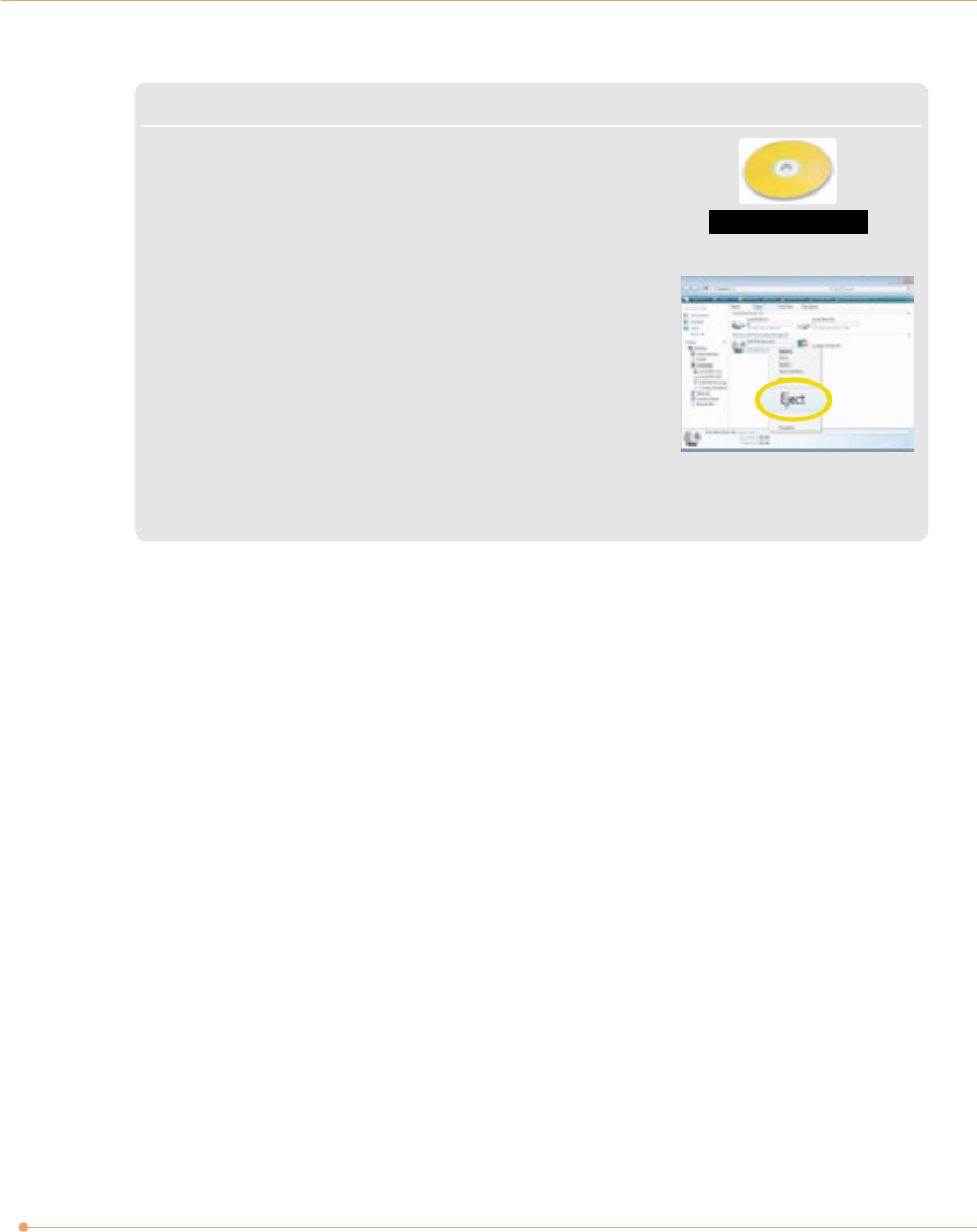
NOTE
✓Your computer is fitted with a slim tray-loading optical drive.
CDs that are not of the standard size cannot be used in this product.
✓If you can not eject a CD/DVD from the optical drive by pressing
the Eject button, follow these steps:
1. Click Start and then click Computer.
2. Right-click on the optical drive that the CD/DVD is in and click
Eject in the popup menu.
✓Additional label(s) on the CD/DVD may cause noise when the optical drive is working. Remove the
label(s) on the CD/DVD for safe use.
CD 120mm
5
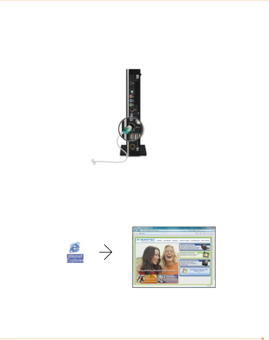
Connect to the Internet
1. Press the power button and the Windows Vista start screen will appear. Connect a LAN cable
to the LAN connector as shown in the figure below.
2. Configure the communication settings for the system based on your communication
environment. When connecting to the Internet via an internet service provider, contact the
service provider for more information on required communication settings.
3. Launch Internet Explorer or other communication software.
MMC
RS-MMC
SD
MS-PRO
MS-PRO Duo
MS
6
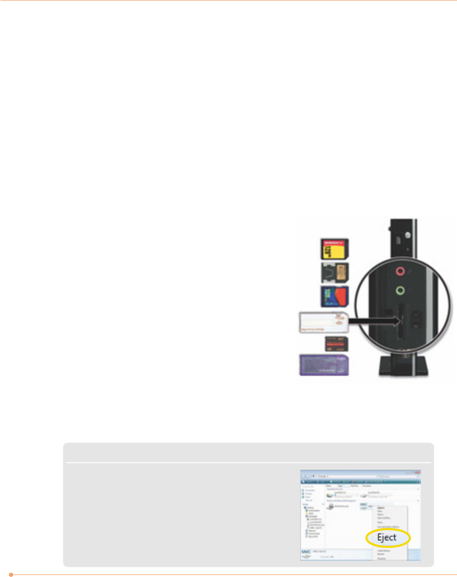
Using the Multi-Card Reader
Averatec's Black Crystal PC accepts 6 types of multi-media cards into the multi-card reader slot
on the front of the PC.
Multi-media card
SD (Secure Digital™), MS-PRO™, MS-PRO™ Duo, MS(Memory Stick™), MMC(MultiMediaCard™), RS-MMC
Inserting the multi-media card
To insert correctly, refer to the pictures. Insert cards with
the label side facing toward the right of the PC.
Removing the multi-media card
Grip the tip of the card and take it out from the slot.
(Do not remove the card while you are using it, as you could corrupt the contents.)
NOTE
✓Click Start and select Computer. On the Computer screen,
right-click on the Combo Socket icon and select Eject.
(This does not physically eject the media card. However,
it does ensure all data is written to the media card prior
to the physical removal of the card)
7
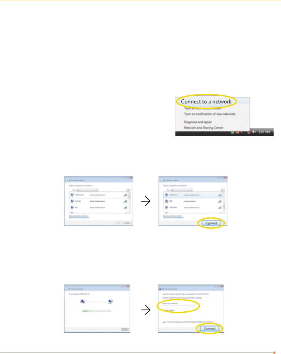
Using the Wireless LAN
To use a wireless network in an office environment where APs (Access Points) are installed, see
the following instructions. (The example used here explains how to use the basic Windows
configuration features to configure the system. You can also use the program that comes with
the wireless LAN card to configure the network.)
1. Right-click on the Wireless Network icon on the
status bar, and then select Connect to a network.
2. If there is an AP-enabled environment, a list of available APs will appear. Click the item you
want to connect to, and click Connect.
3. A window will appear displaying Connecting to xxxxx (Where XXXXX is the name of your
router/AP). If a Security key or password is set up, a window will appear where you can enter
the security key or password. Enter the security key or password, and click Connect. (The
window will not appear if no security key or password is set up.)
8
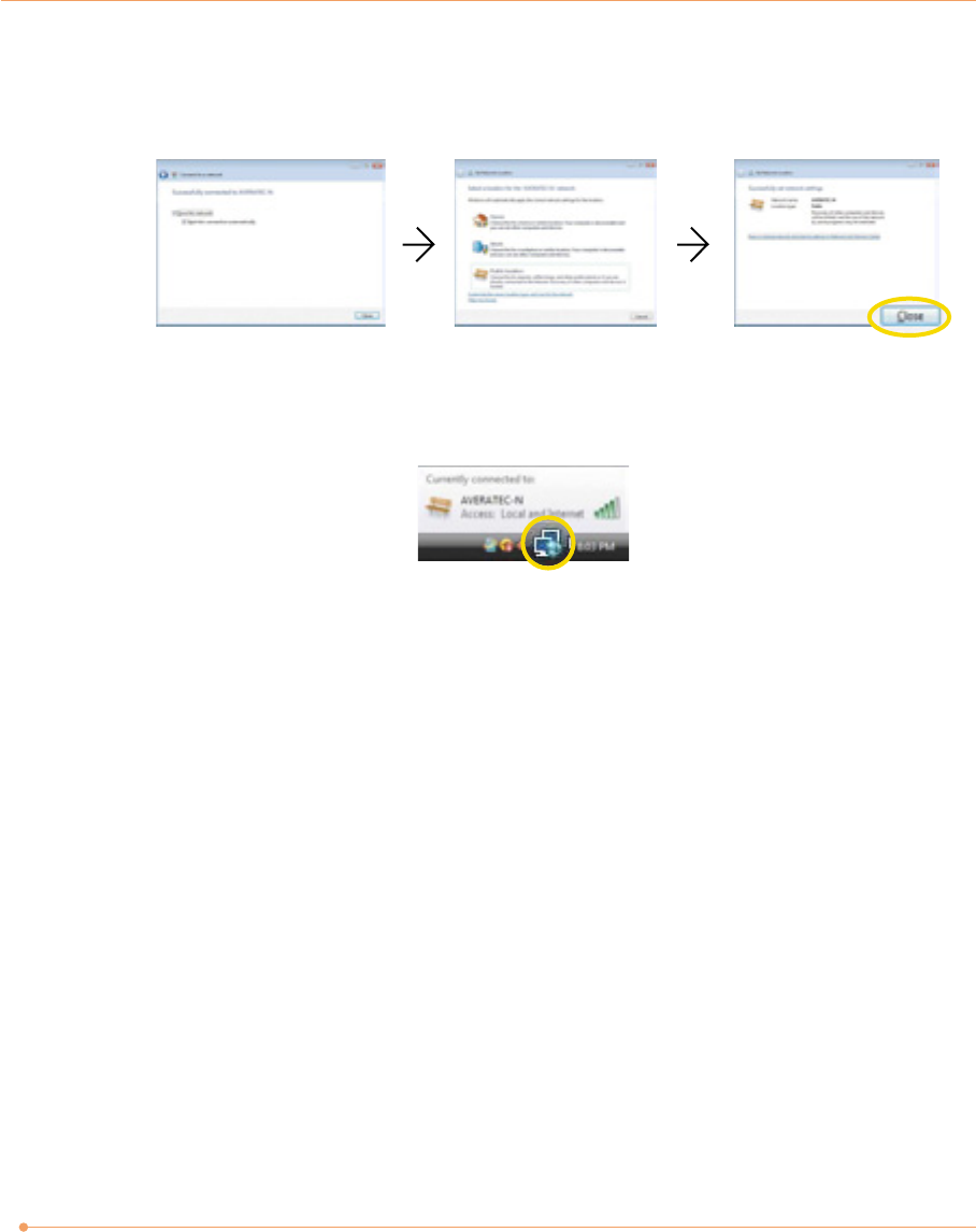
4. When the Successfully connected to xxxxx window appears, confirm the settings and then click
Close.
5. Once connection is successfully established, the network icon on the status bar will change its
shape.
Select the right items for your environment, and click Close.
9
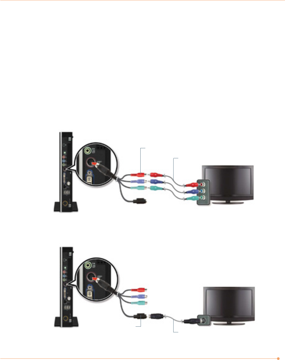
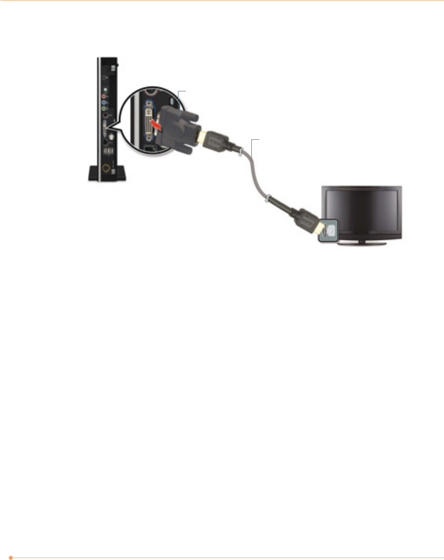
Connecting the TV
You can display the screen through the optional TV connection ports.
To connect the TV, follow these steps:
1. Determine how you will connect the TV to your PC.
2. Connect the video cable or the DVI to HDMI convert adapter to your PC and connect the
component cables, S-video cable or HDMI cable to the TV.
Component cables
Component connectors
Component
S-video cable
S-video connector
S-video
10
3. You should now be able to view the screen on the TV.
DVI to HDMI convert adapter (not included)
HDMI cable
HDMI
11
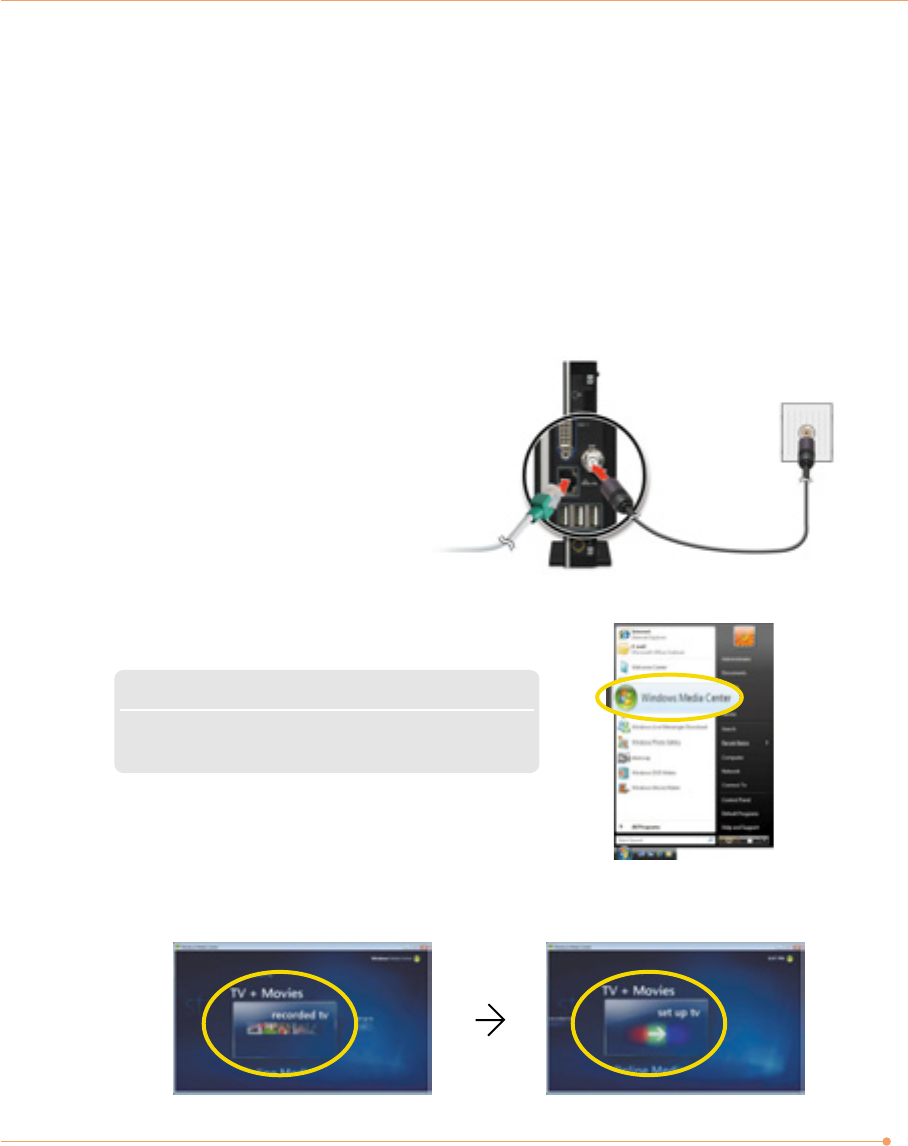
Watching TV (if equipped with optional TV
tuner)
You can connect a TV antenna to the PC.
Connecting an external antenna cable directly to the
system to watch TV
1. Connect an antenna cable to the TV tuner.
2. Click Start and then select Windows Media Center.
3. Click TV + Movies. To set up the TV, follow the instructions on the screens.
NOTE
✓When the Start screen appears, on your first use, select
Quick Installation and then click OK.
12
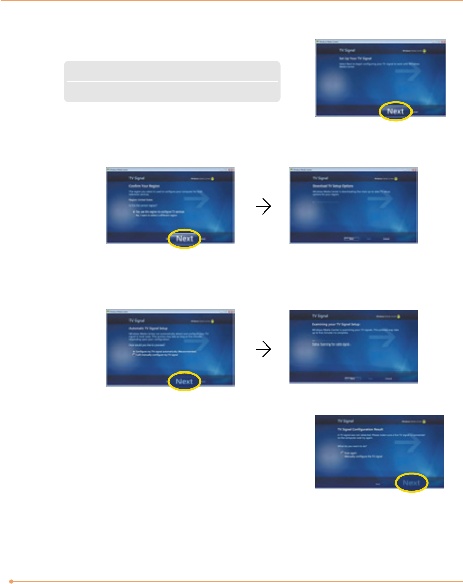
NOTE
✓If you haven’t already done so, connect to the Internet.
4. When the TV Signal screen appears, click Next.
5. When the Confirm Your Region screen appears, choose your region and then click Next.
6. When the Automatic TV Signal Setup screen appears, select how you would like to proceed and
then click Next. (Choosing Configure my TV signal automatically is recommended here.)
7. If TV signals are configured normally, select Yes and then
click Next. (If necessary, you can manually configure TV
signals.)
13
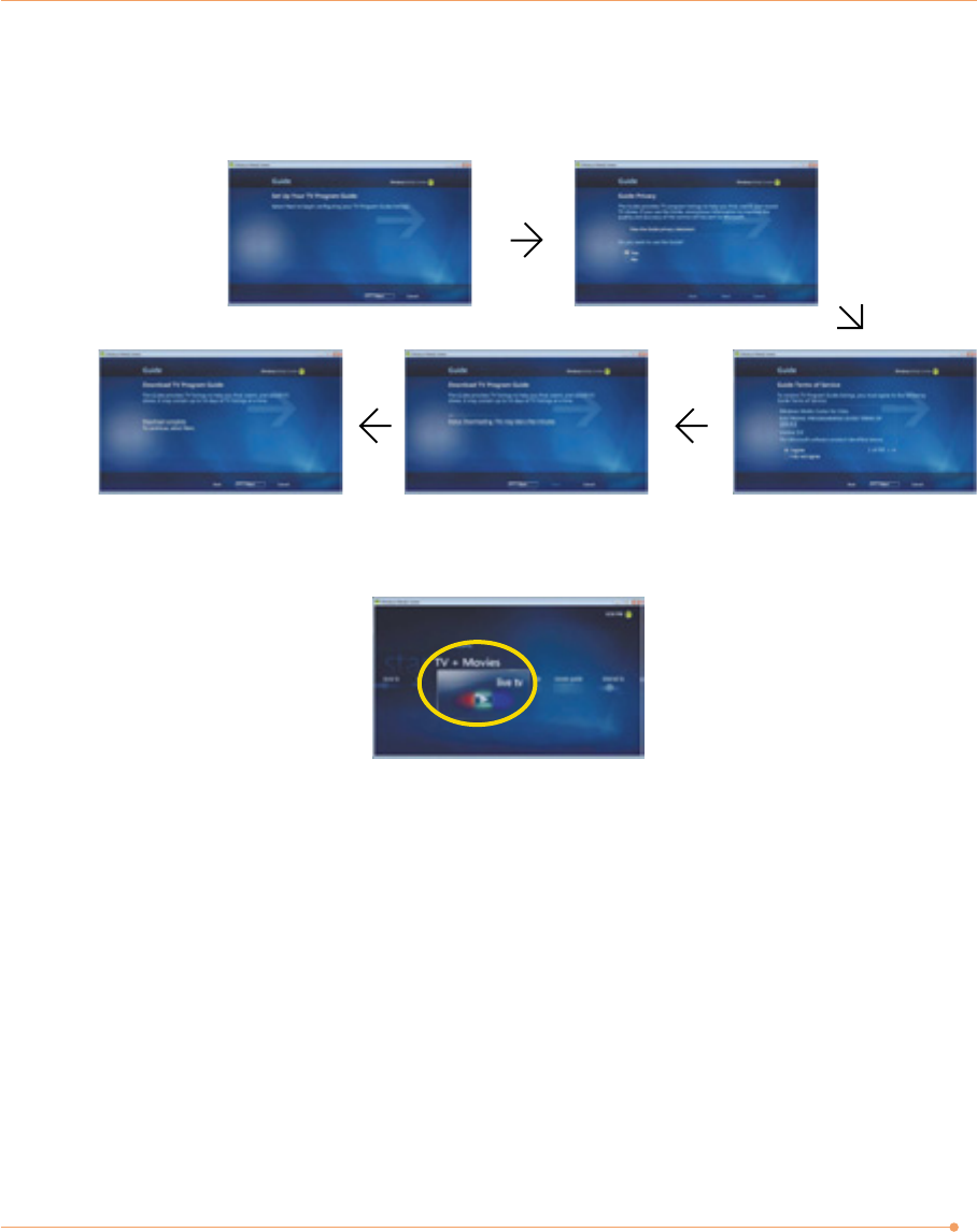
8. When the Guide screen appears, follow the online instructions to install the program.
(The installation method varies depending on the user environment.)
9. In the TV+Movies menu, move to live TV and click on it. Now you are set to watch TV.
14
System SETUP
For System Setup, setup only the items that you need. Note that incorrect settings of Setup
items could result in system malfunction. After powering on the system, press <Del> to enter
the System Setup screen.
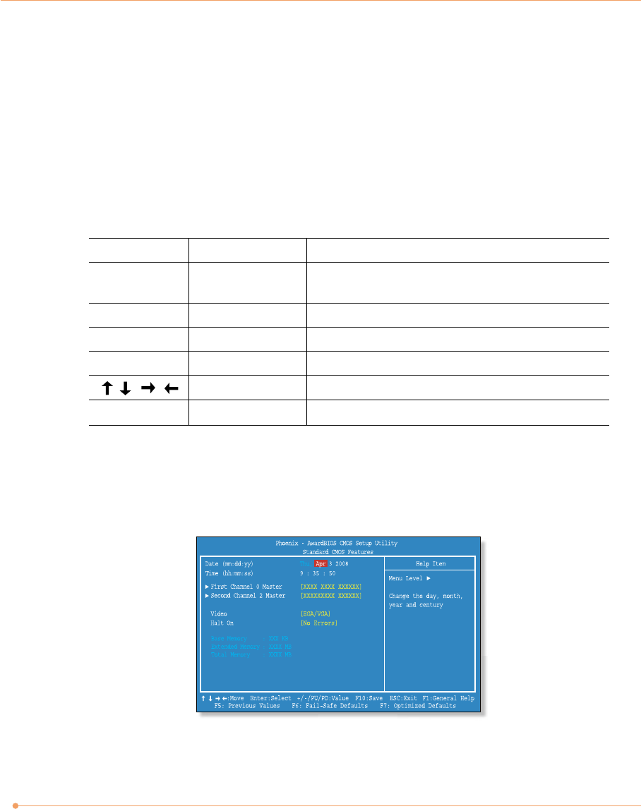
Standard CMOS Features
Sets most standard specifications for the system, such as the time, date and HDD settings.
BIOS Action Keys
Leaves a sub-menu to return to the previous menu
OR exits the BIOS setup while saving changes.
Shows the Sub Menu
ESC Exit
Enter Select
Function Key Command Description
Shows the Help ScreenF1 General Help
Saves changes and reboots the computer.F10 Save and Exit
Selects the next item.Select an item
Selects the next value within a field.-/+ value
15
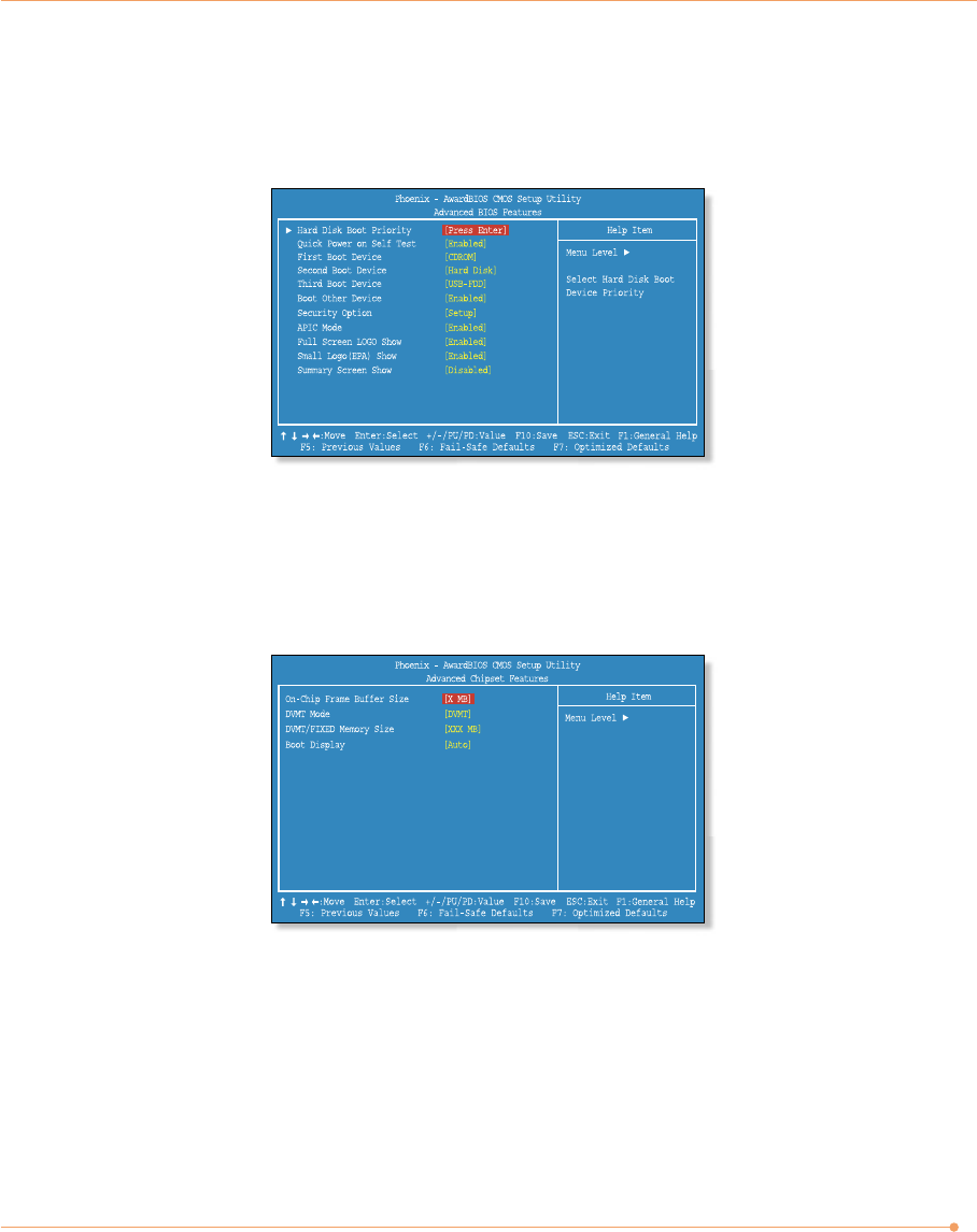
Advanced Chipset Features
Configure on-chip Frame Buffer Size, DVMT Mode and Boot Display.
Advanced Features
Sets up key items related to the system’s performance, and options about booting.
16
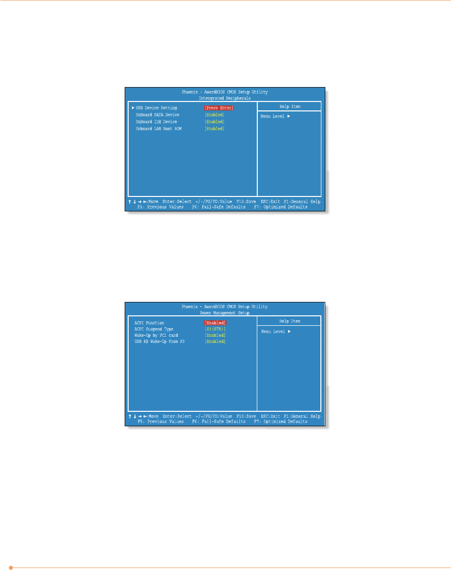
Integrated Peripherals
Sets up options about the chipset and internal speaker built into the main board.
Power Management Setup
Sets up options for managing system power.
17
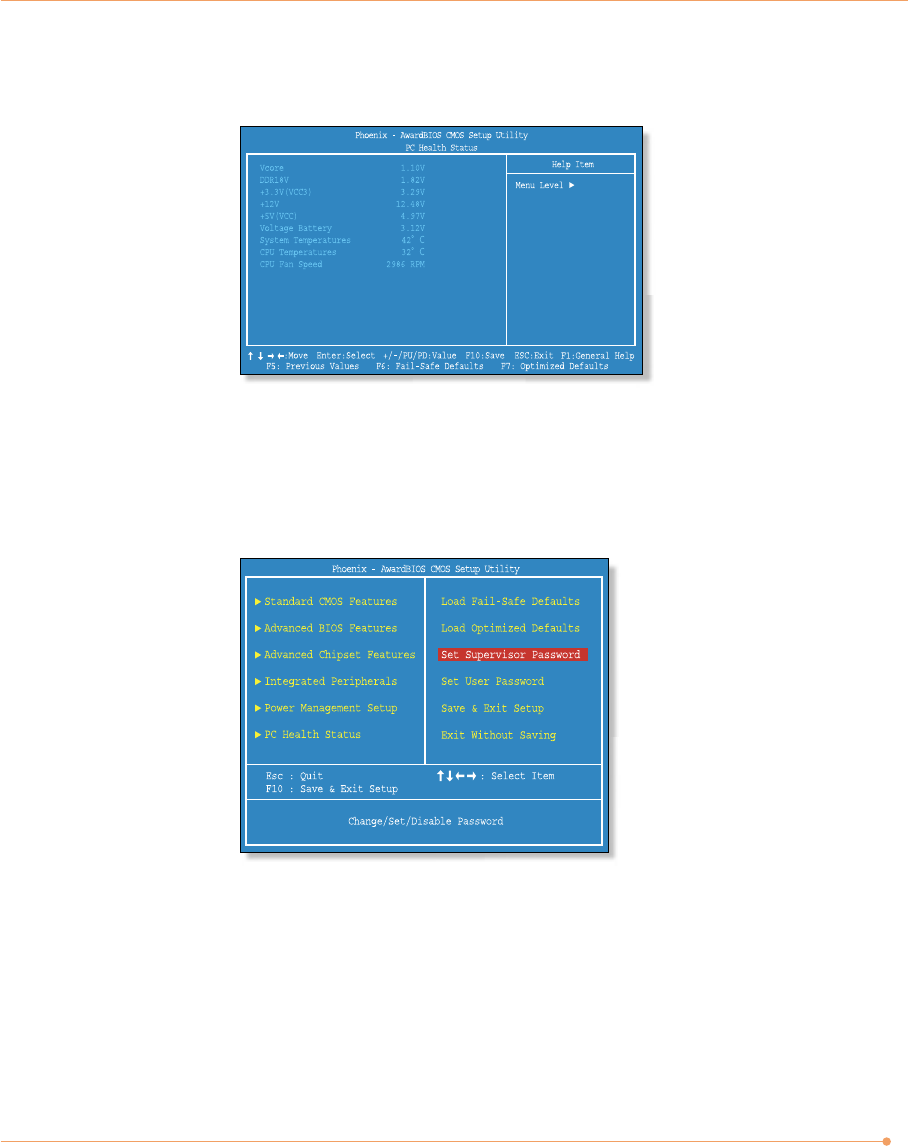
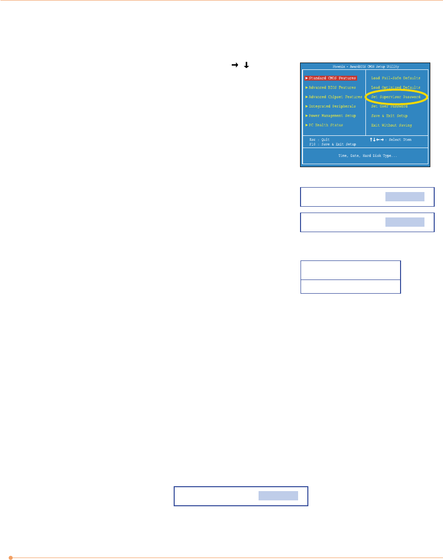
Set Supervisor/User Password
Sets up a password to prevent any unauthorized user from accessing the system.
PC Health Status
18
The Supervisor Password is at a higher level than the User Password.
Changing a password
You can change a password with the same way as “Setting a password.”
Deleting a password
To delete a password, follow these steps:
1. Move to the Set Supervisor/User Password menu and press <Enter>.
2. On the following screen, press <Enter> without any input.
3. On the following screen, press <Enter>.
1. On the initial System Setup screen, press < / > to go to
the Set Supervisor/User Password menu and then press
<Enter>.
Setting a password
2. On the following screen, enter the password and then
press <Enter>.
3. If you entered the correct password, the following
window will appear. Press <Enter>.
Then enter the same password again and press <Enter>.
This completes setting up a password.
Enter Password
Confirm Password
Password installed
[OK]
Enter Password

19
Expanding the Main Memory
There may come a time when you will want to expand the main memory capacity in your
computer. When expanding the main memory, make sure that the specifications of any newly
added memory and the currently installed memory are the same. The following instructions are
provided to those who are familiar with system assembly/disassembly in order to help them to
find the memory specification. If you are not familiar with system assembly/disassembly or do
not know your memory specification, you should not perform the memory upgrade. Please
contact customer support for assistance.
The motherboard has two SO-DIMM sockets, which can accommodate up to 4.0 GB of memory.
If new memory is installed, its type, size and speed are automatically checked by the system
BIOS.
Each of the SO-DIMM sockets supports the following memory specification:
200-pin DDR2 SDRAM Socket, Dual-Channel Support, 533/667 MHz DDR2 SDRAM Memory
Interface.
The appearance of the SO-DIMM memory in the figure may not reflect the actual memory,
depending on the system model.
1. Before proceeding, make sure that the system is turned off, that you are wearing an anti-
static wrist strap (available in most computer shops), and that your workspace is dust and
smoke-free.
CAUTION
✓Your PC uses the SO-DIMM socket for memory. For expanding the memory, you must purchase the
SO-DIMM memory for installing. You can’t install the DIMM memory in your PC. The general desktop
PC uses the DIMM socket for memory.
20
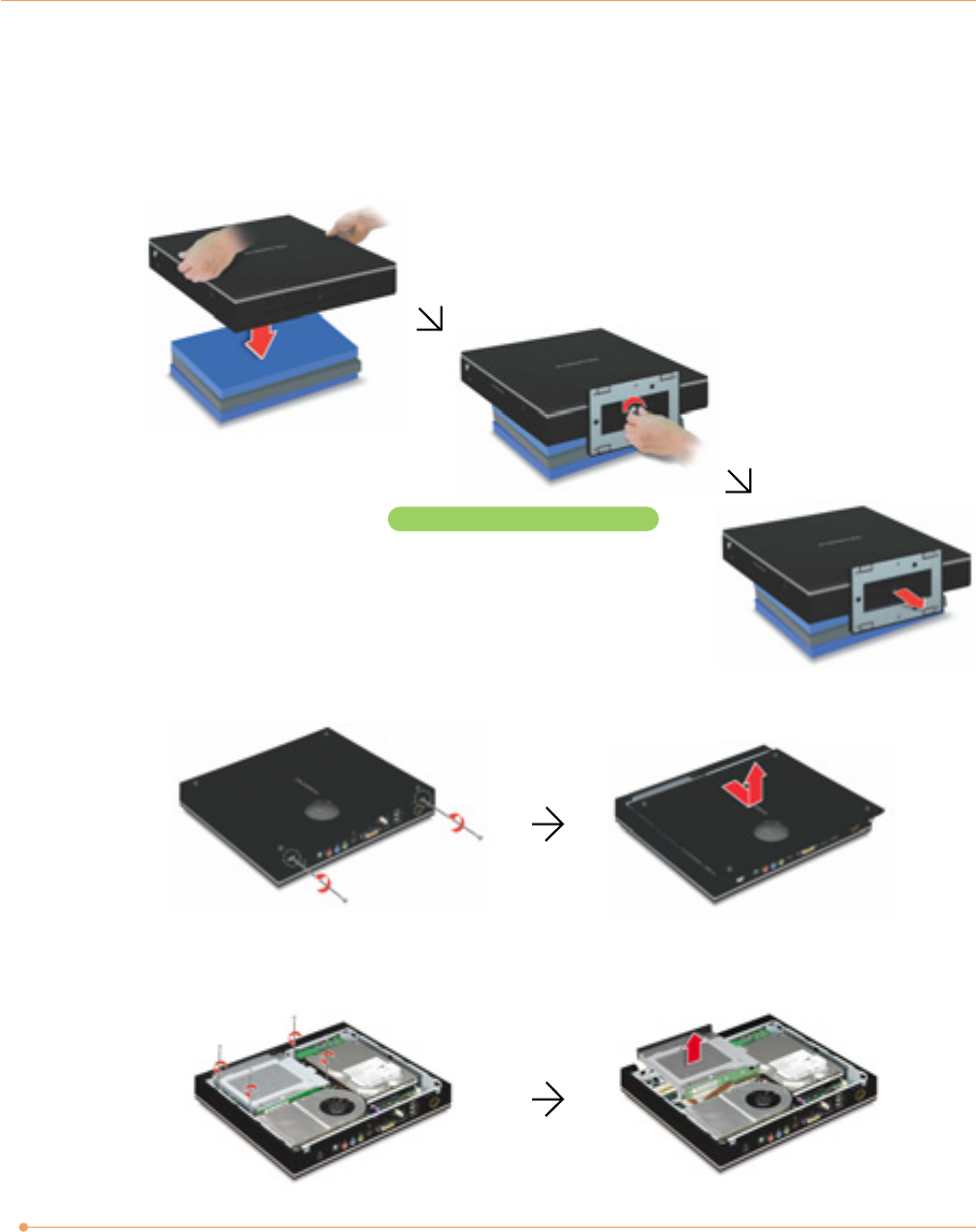
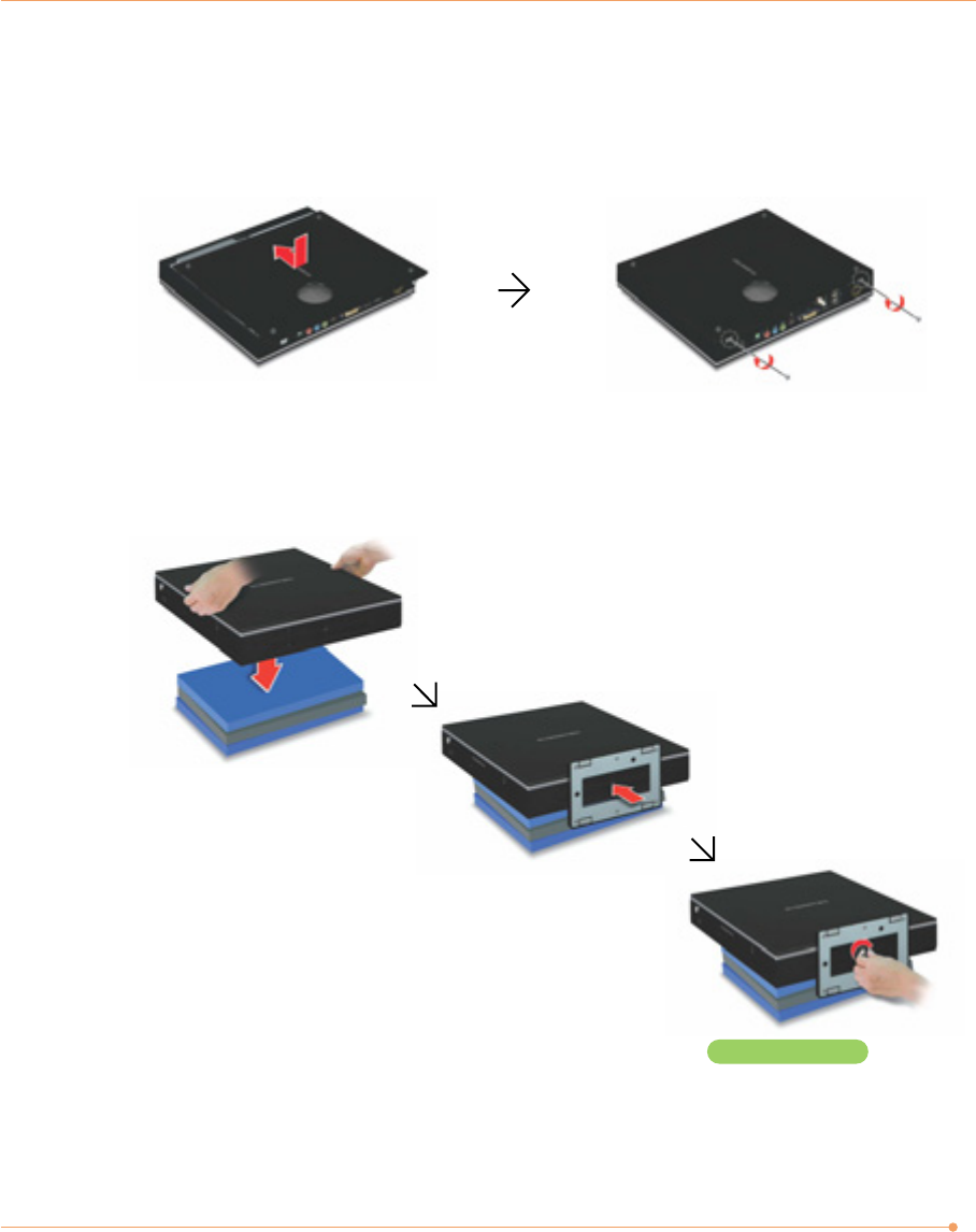
2. Removing the system stand
Place the system on the flat thing (such as the books) and remove the screws and system
stand as shown in the figure.
3. Remove the left side cover and CD drive
1) Remove the screws and left side cover.
2) Remove the screws and lift up the CD drive.
Remove the screws from the stand
21
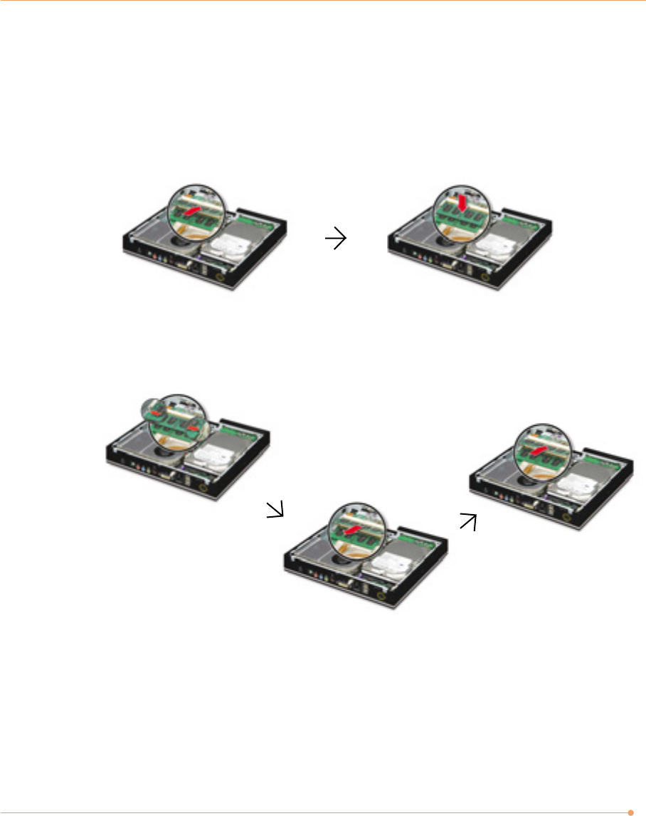
4. Installing the memory
You can install the memory into the empty socket. If there is no empty socket, you can replace
the old memory with the new memory module.
To remove the memory, pull the latches on both edges of the socket away at the same time.
The memory will pop up about 30 degrees. Remove it from the socket.
To install the memory, align the notch on the new DIMM with the notch on the memory socket,
insert the memory into the socket at a slight angle (about 30 degrees) firmly, and gently press
down the memory until both latches snap into place.
22
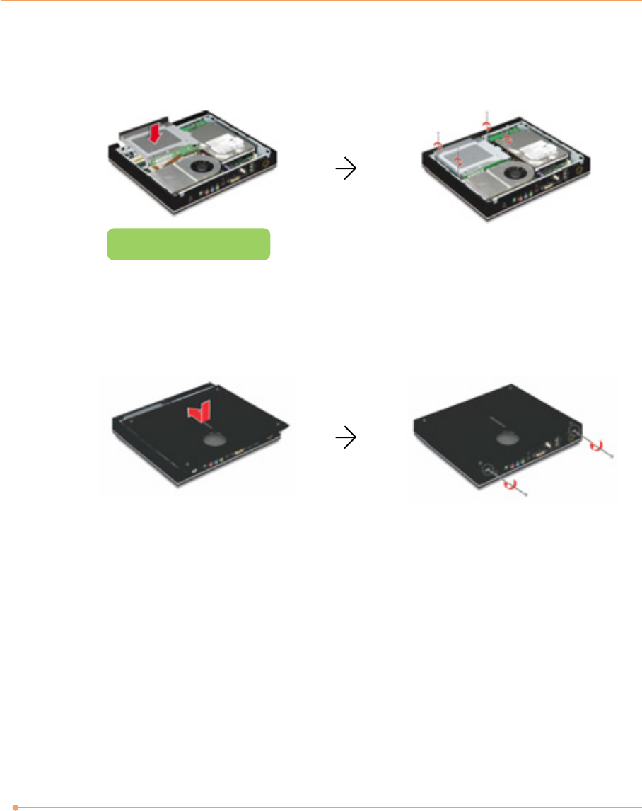
5. Replacing the CD drive
Replace the CD drive and then fasten the screws.
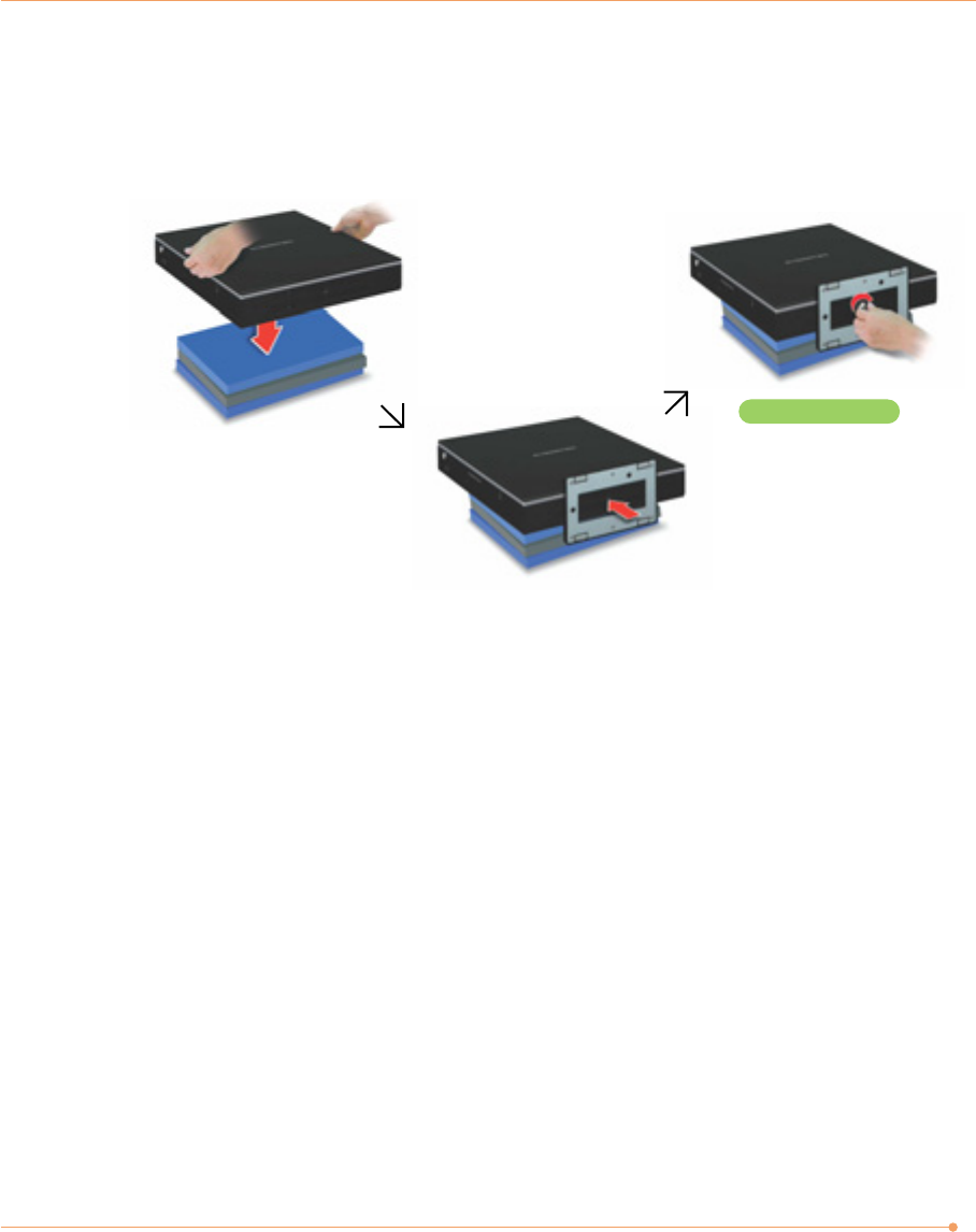
6. Replacing the left side cover
Fit the tabs on the left side cover to the holes of the system chassis and push the cover to front,
and then replace the screws.
Be careful not to bend the pins
on the connect board.
23
7. Replacing the stand
Place the system on the flat thing, such as the books, and attach the stand, and then replace
the screws.
8. Checking memory capacity
Once the memory installation is complete, restart the system. If an error message related to the
memory capacity appears upon booting, press the Del key to enter the system setup screen.
Save the setting and exit.
Replace the screws.
24
Replacing the Hard Disk Drive
Before you replace the hard disk drive, don’t forget to back up all your important data.
The instructions on replacing hard disk drives are for those users who have an understanding of
hard disks and are familiar with system assembly and disassembly. If you are not one of those
users, please contact the service center and have them replace your hard disk drive for you.
1. Before proceeding, make sure that the system is turned off, you are wearing an anti-static
wrist strap (available in most computer shops), and your workspace is dust and smoke-free.
2. Removing the system stand
Place the system on the flat things (such as the books) and remove the screws and stand as
shown in the figure.
CAUTION
✓For replacing, use a 5.25” SATA hard disk drive.
Remove the screws from the stand
25
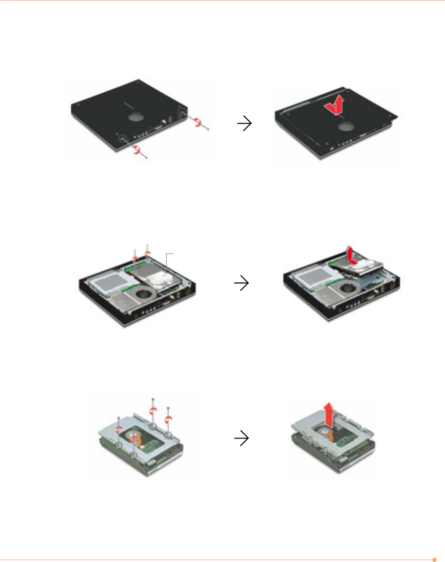
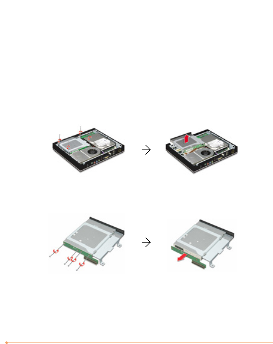
3. Removing the left side cover
Remove the screws and left side cover.
4. Removing the hard disk drive
Remove the screws, slide the hard disk drive to front about 0.7 cm for disconnecting, and lift
up the hard disk drive.
5. Detaching the mounting bracket from the hard disk drive
Remove the screws that fix the hard disk drive, and then detach the hard disk drive.
Hard disk drive
26
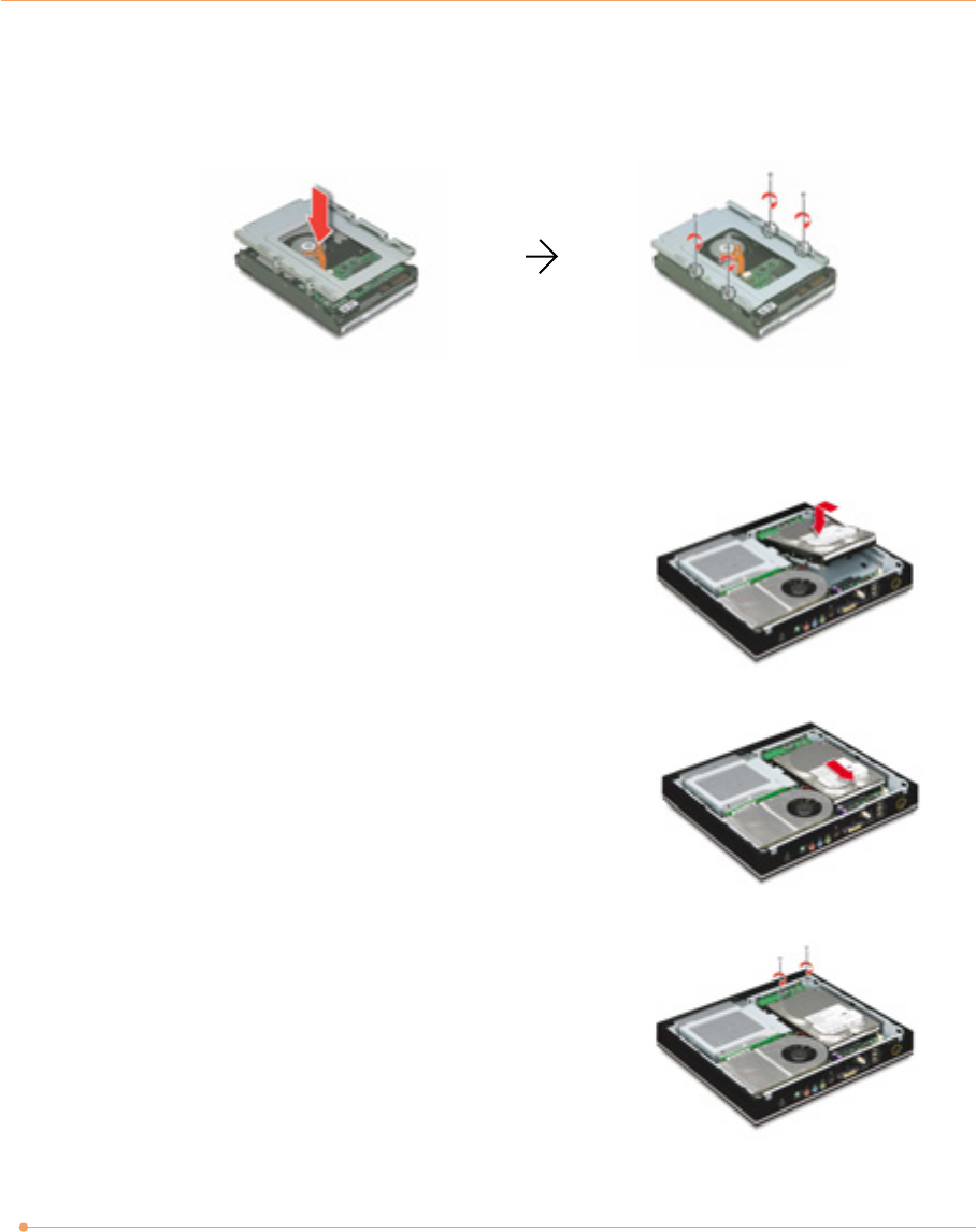
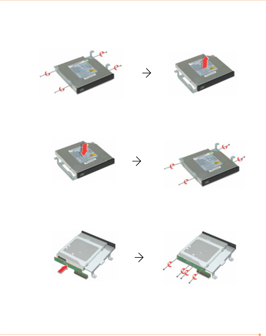
6. Installing the mounting bracket to the new hard disk
Install the mounting bracket to the new hard disk drive and secure it with the screws.
7. Replacing the hard disk drive
To replace the hard disk drive, follow these steps:
1) Insert the front side of the hard disk drive into the
chassis first and fit the holes on the mounting
bracket to the tabs of the chassis.
2) Push the hard disk drive to the rear side of the
system to connect.
3) Replace the screws.
27
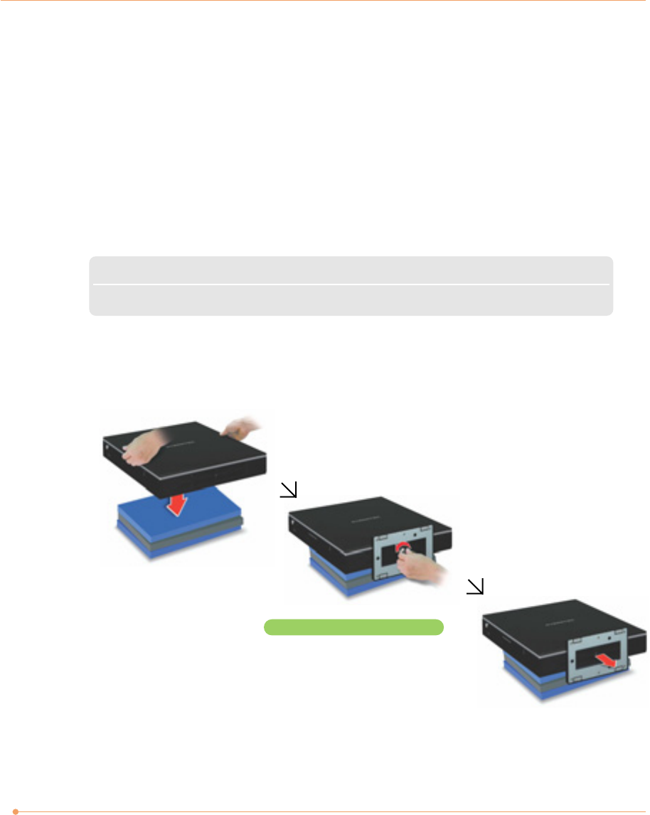
8. Replacing the left side cover
Fit the tabs on the left side cover to the holes of the system chassis and push the cover to front,
and then replace the screws.
9. Replacing the stand
Place the system on the flat thing (such as the books) and replace the stand with the screws.
Replace the screws.
28
Replacing the CD Drive
When you replace the CD drive, make sure that the new one has specifications equivalent to the
old one. (For instructions on replacing the CD drive, see the instructions on “Expanding the
Main Memory.” If you are unsure of the CD drive standard, contact the service center and have
them replace the CD drive.)
1. Removing the stand, left side cover, and CD drive
Refer to the steps from 1 to 3 on “Expanding the Main Memory” for removing the stand, left
side cover, and CD drive.
2. Removing the interface board from the CD drive
Remove the screws and detach the interface board from the CD drive.
29
4. Attaching a new CD drive to the mounting bracket
After attaching a new CD drive, secure it with the screws to the mounting bracket.
5. Replacing the interface board to the CD drive
Replace the interface board with the screws to the CD drive.
6. Replacing the stand, left side cover, and CD drive
Refer to the steps from 5 to 7 on “Expanding the Main Memory” for replacing the stand, left
side cover, and CD drive.
3. Removing the mounting bracket from the CD drive
Remove the screws that fix the CD drive and then detach the CD drive.
30
Installing the Optional MXM Video Card
If you purchase the model without the MXM video card, you can install the optional MXM
video card for upgrading the video performance of your system.
CAUTION
✓Please contact us for purchasing the optional MXM video card. Not all MXM video cards are compatible
with the Black Crystal PC.
1. Removing the stand, left side cover, and CD drive
Refer to the steps from 1 to 3 on “Expanding the Main Memory” for removing the stand, left
side cover, and CD drive.
To install the optional MXM video card, follow these steps:
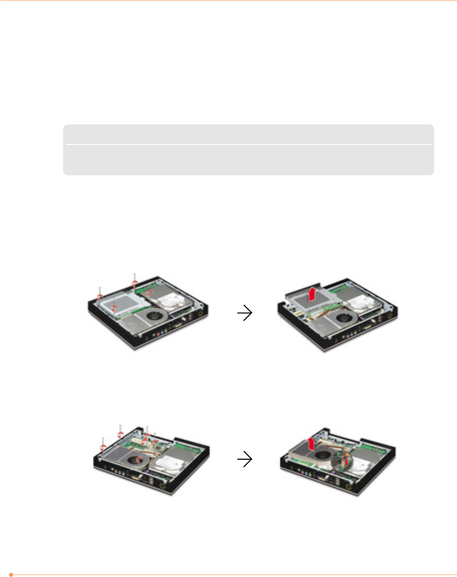
2. Removing the CPU thermal module
Remove the screws and the CPU fan cable, and then remove the CPU thermal module.
31
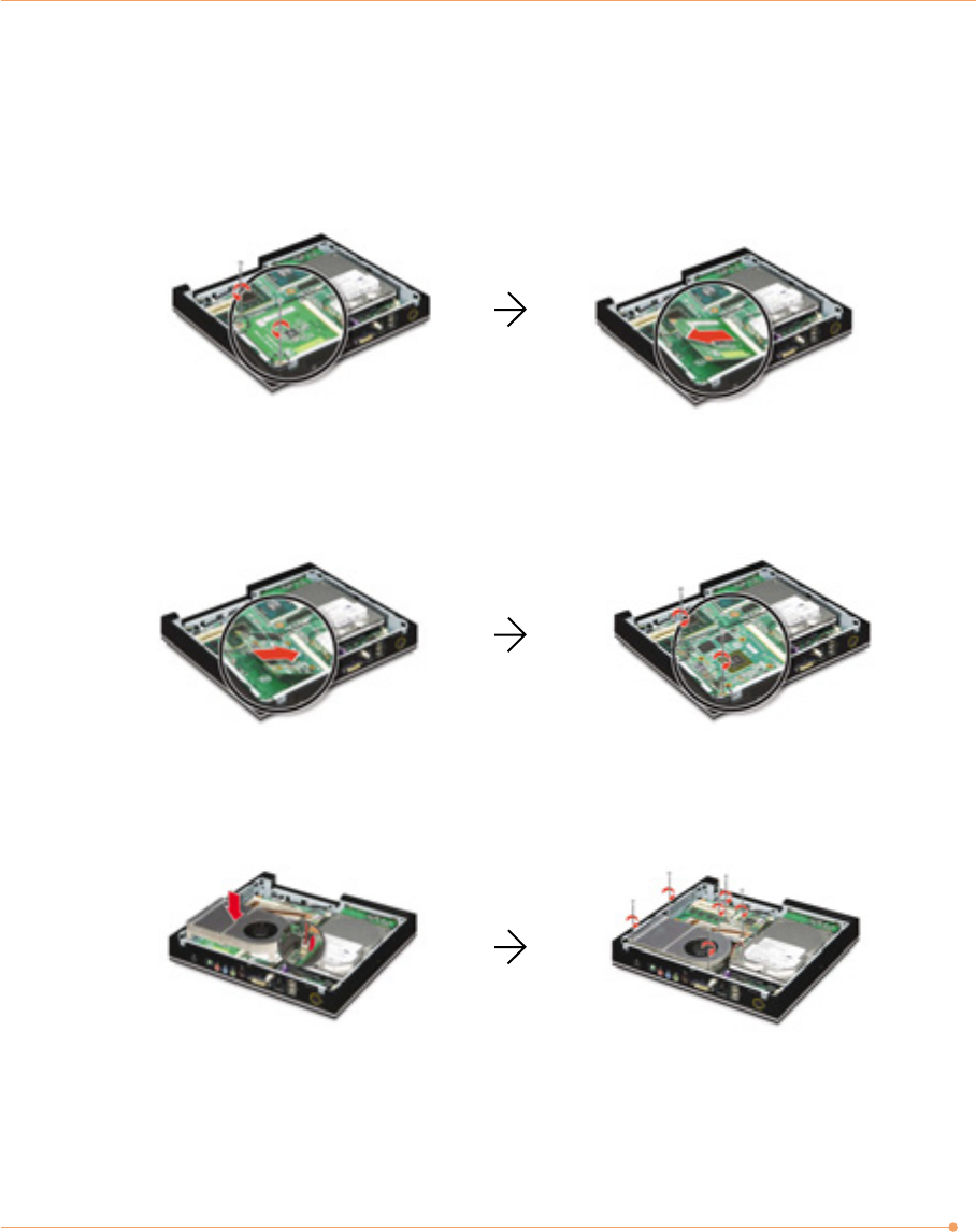
3. Removing the dummy board from the MXM socket
Remove the screws that secure the dummy board and then remove the dummy board from the
MXM socket. (Please do not discard this dummy board. If you don’t want to use the MXM video
card, you must install this dummy board in the MXM socket.)
4. Installing the MXM video card
Insert the MXM video card firmly and secure it with the screws as shown in the figure.
5. Replacing the CPU thermal module
Replace the CPU thermal module and the CPU fan cable, then replace the screws.
6. Replacing the stand, left side cover, and CD drive
Refer to the steps from 5 to 7 on “Expanding the Main Memory” for replacing the stand, left
side cover, and CD drive.