TriGem Computer PT1400 NoteBook PC User Manual Averatec PT1400 ATT E Rev 1
TriGem Computer, Inc NoteBook PC Averatec PT1400 ATT E Rev 1
User manual

FCC ID: C8VPT1400
HCT CO., LTD.
SAN 136-1, AMI-RI, BUBAL-EUP, ICHEON-SI, KYOUNGKI-DO, 467-701, KOREA
TEL:+82 31 639 8517 FAX:+82 31 639 8525 www.hct.co.kr
Report No. : HCTR0909FR10 1/1
ATTACHMENT E.
- User Manual -
AVERATEC PT1400
User's Guide

i
Before You Start
Regulatory Information
FCC-B Radio Frequency Interference Statement
This equipment has been tested and found to comply with the limits for a Class B digital device, pursuant to part 15 of the FCC rules.
These limits are designed to provide reasonable protection against harmful interference in a residential installation. This equipment
generates, uses and can radiate radio frequency energy and, if not installed and used in accordance with the instructions, may cause
harmful interference to radio communications. However, there is no guarantee that interference will not occur in a particular
installation. If this equipment does cause harmful interference to radio or television reception, which can be determined by turning
the equipment off and on, the user is encouraged to try to correct the interference by one or more of the following measures:
X
Reorient or relocate the receiving antenna.
X
Increase the separation between the equipment and receiver.
X
Connect the equipment into an outlet on a circuit different from that to which the receiver is connected.
Note
p
4HECHANGESORMODIFICATIONSNOTEXPRESSLYAPPROVEDBYTHEPARTYRESPONSIBLEFORCOMPLIANCECOULDVOIDTHEUSERS
AUTHORITYTOOPERATETHEEQUIPMENT
p
3HIELDINTERFACECABLESAND!#POWERCORDIFANYMUSTBEUSEDINORDERTOCOMPLYWITHTHEEMISSIONLIMITS
ii
Before You Start
FCC Conditions
This device complies with part 15 of the FCC Rules. Operation is subject to the following two conditions:
1
.Thisdevice maynotcause harmfulinterference.
2
.This device must accept any interference received, including interference that may cause undesired operation.
FCC RF Radiation Exposure Statement
1
.This transmitter must not be co-located or operating in conjunction with any other antenna or transmitter.
2
.This equipment complies with FCC RF radiation exposure limits set forth for an uncontrolled environment. To maintain
compliance with FCC RF exposure compliance requirements, avoid direct contact to the transmitting antenna during
transmitting.
3
.
may void the user’s authority to operate the equipment.
RF Exposure Warning
ThisequipmentcomplieswithFCC RFexposure limitssetforth foranuncontrolledenvironment. This equipmentmust notbe
co-located or operating in conjunction with any other antenna or transmitter.
SAR Value: 0.023 W/kg

iii
Before You Start
Ethernet Notice
This equipment is intended for indoor use only and all the wiring is designed for indoor use.
Battery Notice
CAUTION 2)3+/&%80,/3)/.)&"!44%29)32%0,!#%$"9!.).#/22%#4490%$)30/3%/&53%$"!44%2)%3!##/2$).'
4/4(%).3425#4)/.3

iv
Before You Start
Safety Instructions
1
. Read the safety instructions carefully and thoroughly.
2
. Save this User Guide for later use.
3
. Keep this equipment away from humidity and high temperature.
4
. Lay this equipment on a stable surface before setting it up.
5
.The openings on the enclosure are used for air convection and to prevent the equipment from overheating. Do not cover
the openings.
6
. Make sure that the power voltage is within its safety range and has been adjusted properly to the value of 100~240V before
connecting the equipment to the power inlet.
7
. Place the power cord in a way that people are unlikely to step on it. Do not place anything on the power cord.
8
. Always unplug the power cord before inserting any add-on card or module.
9
. All cautions and warnings on the equipment should be noted.
10
. If any of the following situations arises, get the equipment checked by a service personnel:
X
The power cord or plug is damaged.
X
Liquid has penetrated into the equipment.
X
The equipment has been exposed to moisture.

v
Before You Start
11
. Never pour any liquid into the computer as this will damage the equipment or cause an electrical shock.
12
. Do not leave the equipment in an unconditioned environment with a storage temperature of 60°C (140°F) or above, as this
may damage the equipment.
13
. To prevent explosion caused by improper battery replacement, use the same or equivalent type of battery recommended
by the manufacturer only.
X
The equipment has not worked well or you can not get it work according to the Users Manual.
X
The equipment was dropped or damaged.
X
The equipment has obvious signs of breakage.
vi
Before You Start
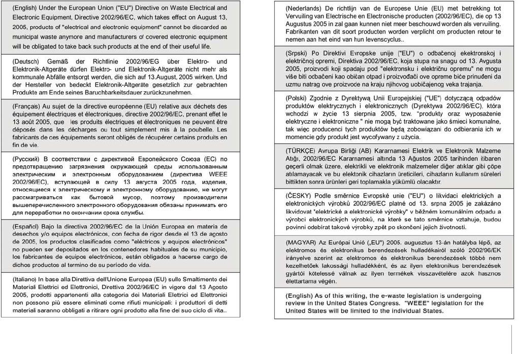
WEEE Statement
vii
Before You Start
Before You Read
The information in this user's guide is subject to change without notice.
TriGem Computer, Inc. shall not be liable for technical or editorial errors or omissions contained herein; nor for incidental or
consequential damages resulting from the furnishing, performance, or use of this material.
AVERATEC is a trademark or registered trademark of TriGem Computer, Inc. in the United States and/or other countries.
All other product and brand names are trademarks of their respective owners.
© 2009 TriGem Computer, Inc. All rights reserved.
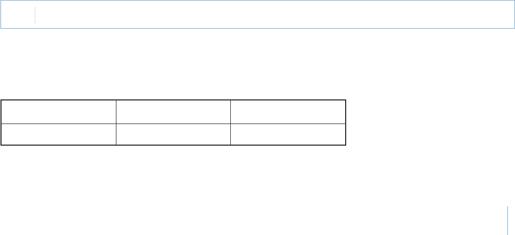
Release History
Version
1.0
Revision Note
First Release
Date
08, 2009
Note $EPENDINGONTHEMODELYOURCOMPUTERSCOMPONENTSMAYVARYANDLOOKSLIGHTLYDIFFERENTTHANTHOSEPICTURED

viii
Before You Start
Table of Contents
Before You Start
Regulatory Information i
Optical Device Drive Notice iii
Battery Notice iii
Ethernet Notice iii
Macrovision Notice iii
Safety Instructions iv
WEEE Statement vi
Before You Read vii
Release History vi
Chapter 1 About Your System
Unpacking 1-1
What is the Averatec PT1400 1-2
Overview 1-4
Chapter 2 Setting Up Your System
Installing the System 2-1
Connecting the Optional Devices 2-2
Installing the Battery 2-3
Connecting the Power Cord 2-4
Turning On Your System 2-5

ix
Before You Start
Setting Up Windows XP for the First Time 2-6
Turning Off Your System 2-9
Chapter 3 Using Your System
Using the Stylus Pen 3-1
Secondary LCD Pivot Calibration 3-5
Using the DVsn Button 3-10
Special Function Buttons 3-11
Using the DVsn, PT, and BEAM Control Program 3-13
Connecting to the Internet 3-17
Using the Battery 3-20
Using Windows XP 3-22
Using the HOLD Switch 3-26
Chapter 4 Using the Multimedia Features
Adjusting the Speaker Volume 4-1
Using the Webcam 4-3
Chapter 5 System SETUP (BIOS)
Entering Setup 5-1
System Setup Options 5-2
Appendix A Specications
Product Specifications A-1

1
Chapter 1 About Your System
About Your System
Chapter
1

1-1
Chapter 1 About Your System
Unpacking
First, unpack the system from the shipping carton and check all items carefully. If any item is damaged or missed, please contact
your local dealer immediately. Keep the box and packing materials in case you need to ship the unit in for service in the future.
The package should contain the following items:
X
Averatec PT1400 system
X
Quick Start Guide
X
20V AC Adapter
X
AC Cord
X
Battery
X
Primary LCD Cover

1-2
Chapter 1 About Your System
What is the Averatec PT1400
Congratulations on your purchase of the system. Your system features the latest advances in portable computing technology.
The system's modular design provides maximum expandability without compromising portability.
Dual LCD Monitor
t Easy to operate dual Touch LCD Monitors with simultaneous (two-way) viewing via the pivot function.
t Offers all the functions of both a PDA and Pocket PC without the limitations.
t Maintains all the similar functions of your typical Windows-based PC.
Presentation Support Function
t Full-screen presentation with simple one-button operation.
Multimedia Function
t Built-in fully functional camera allows for operation of all built-in applications as well as imaging and audio recording.
t Convenient camera programs with touch button.
t Dual speaker with high fidelity sound.

1-3
Chapter 1 About Your System
Support of Wireless Communication and High-speed Data-transportation
t
Increased mobility with the wireless LAN
t
High-speed data transport support with external devices, via the built-in USB 2.0 ports
Convenient Mobility / Splendid Design
t
Employed external icon-touch button for simple design and convenient operation.
t
14-inch notebook size with high mobility.
1-4
Chapter 1 About Your System
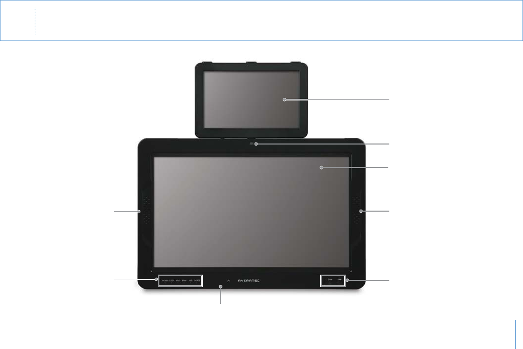
Overview
Front View
Note
p
%XTERNALAPPEARANCEANDCOLOROFTHECOMPUTERMAYBEDIFFERENTFROMTHEPICTURE
p
3HAPEANDSIZEOFTHEICONONTHEPRODUCTMAYDIFFER
Secondary LCD
Webcam
Primary LCD
SpeakerSpeaker
LED indicators
Microphone
Touch sensor buttons
1-5
Chapter 1 About Your System
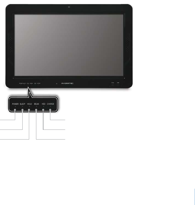
LED indicators
HDDSleep (stand-by)
Beam connection HOLD (locking)
Battery LEDPower ON/OFF
1-6
Chapter 1 About Your System
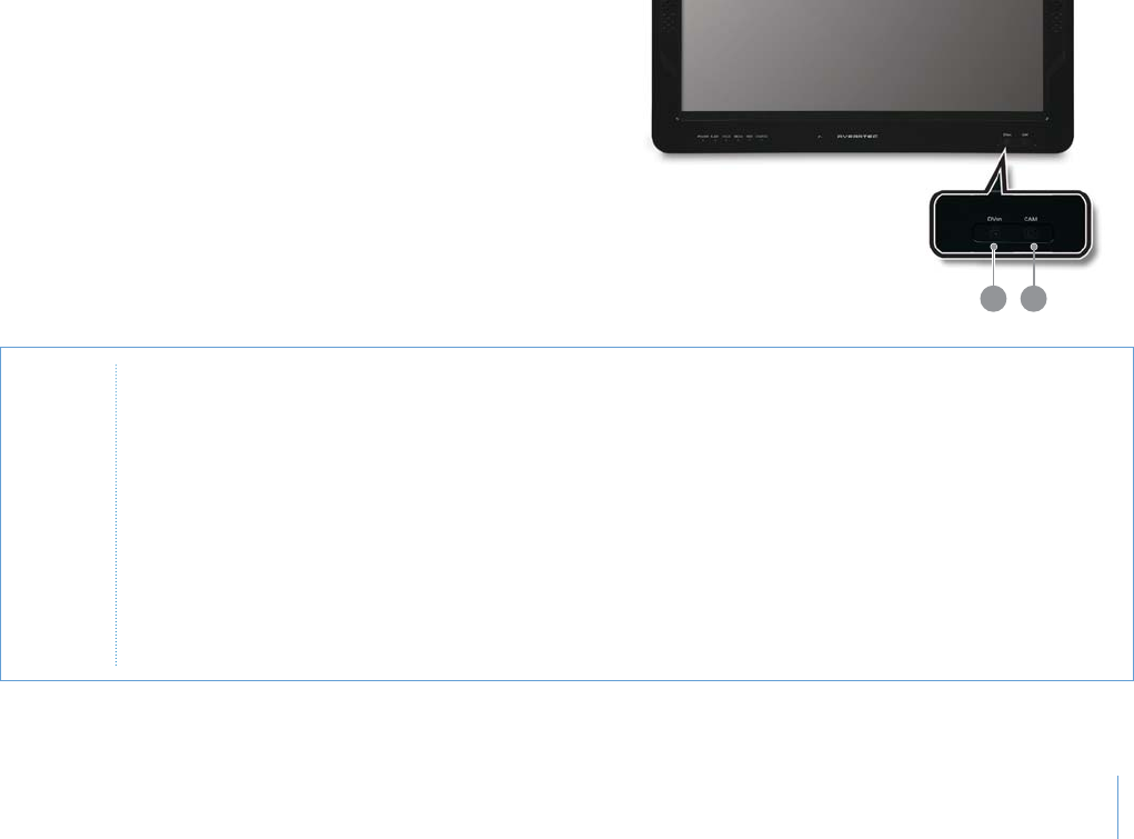
1
.DVsn(LCD screen change)
This function is used to change the LCD screen into
dual mode, extended mode, or switching mode.
2
.CAM(camera)
Operates the camera to record and replay video.
Touch sensor buttons
1 2
CAUTION
p
4OUCHSENSORBUTTONONLYWORKSWHENTHECOMPUTERIS/.
p
5SETHETOUCHSENSORBUTTONWITHCLEANANDDRYHANDS2EMOVEANYMOISTUREFROMYOURHANDSORSURFACEOFTHE
BUTTONINHUMIDENVIRONMENTS
p
4OUCHSENSORBUTTONNORMALLYWORKSWITHSLIGHTTOUCH$ONOTPRESSONITTOFORCEFULLY4OUCHSENSORBUTTONMAYBE
DAMAGEDBYASTRONGSHOCK
p
$ONOTUSEPOINTEDITEMSSUCHASAKNIFEORBALLPOINTPEN0OINTEDTHINGSMAYDAMAGETHETOUCHSENSORBUTTON
p
7HENYOUPRESSTHETOUCHSENSORBUTTONBECAREFULNOTTOTOUCHOTHERFUNCTIONS!CCURATELYPRESSTHEREQUIRED
FUNCTIONOFTOUCHSENSORBUTTONWITHYOURFINGERTIP
p
4OUCHSENSORBUTTONMAYNOTOPERATENORMALLYWHENYOUWEARGLOVESORWHENTHEPRODUCTISCOVEREDBYVINYLOR
OTHERTYPESOFSCREENPROTECTORS
p
$UETOTHESENSITIVITYOFTHETOUCHPANELITISRECOMMENDEDTOAVOIDANYCONTACTWITHANYCONDUCTIVEMATERIALS
1-7
Chapter 1 About Your System
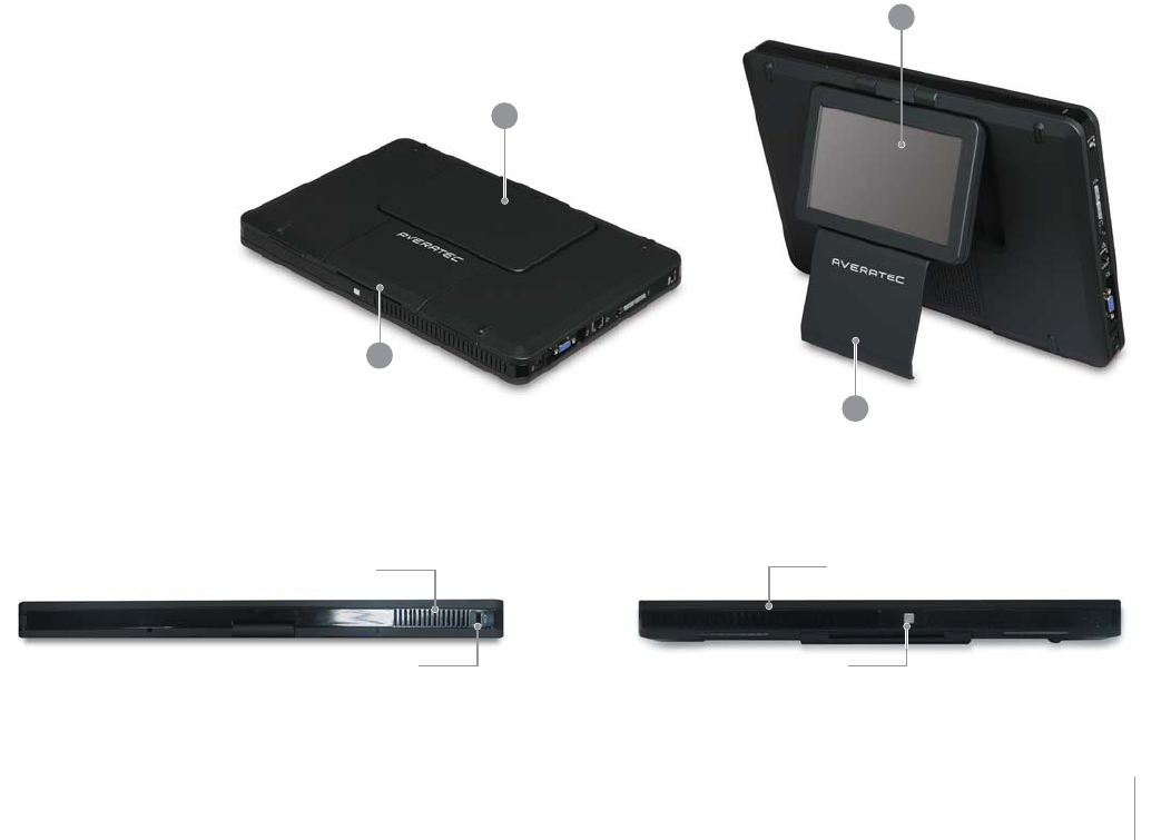
1
.Secondary LCD
2
.Stand
Back Side
Top and Botton Side
2
1
1
2
Kensington lock
Cooling vents
Battery release button
Cooling vents
1-8
Chapter 1 About Your System
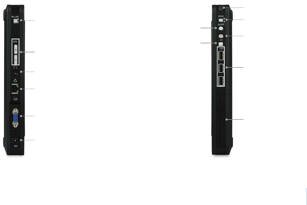
Left Side Right Side
HOLD switch
Power button
Sleep button
Presentation button
USB ports
Battery
Stylus pen
Wireless LAN ON/OFF switch
Volume control button
Headphone jack
LAN port
D-Sub connector
Power connection jack

Setting Up Your System
Chapter
2
2-1
Chapter 2 Setting Up Your System
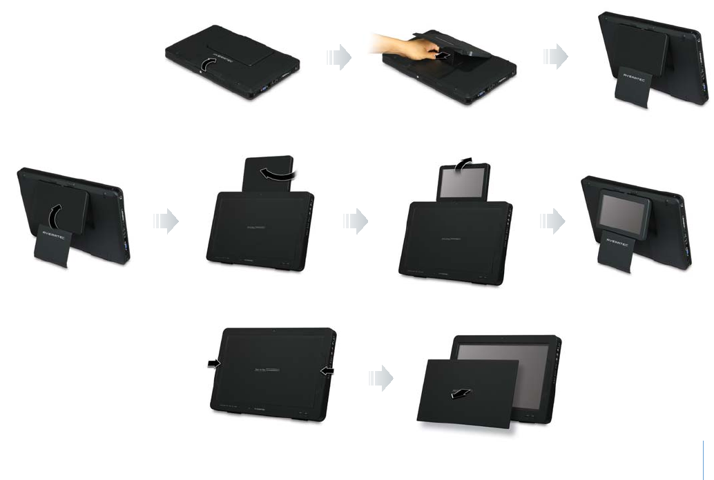
Removing the LCD Cover
Rotating the Secondary LCD
Pull down the stand support plate
to the locking position.
Installing the System
Unfolding the Stand
Turn the secondary LCD clockwise.
Do not turn it counter-clockwise.
2-2
Chapter 2 Setting Up Your System
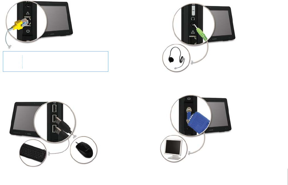
Connecting the Optional Devices
1
.Connect to the Internet
2
.Connect the audio peripherals
4
.Connect the display device (optional)
3
.Connect the keyboard and mouse
(USB)(Not included)
Note 9OUCANALSOCONNECTTOTHE)NTERNET
USINGTHEWIRELESS,!.

2-3
Chapter 2 Setting Up Your System
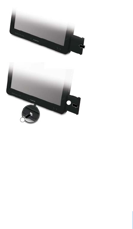
Installing the Battery
To install the battery, insert it into the battery slot. The installed
battery pack charges automatically any time the computer is
connected to the AC adapter.
WARNING
/NLYUSEBATTERIESTHATAREAPPROVEDBYANAUTHORIZEDDEALER!LLBATTERIESARENOTTHESAMEANDTHEREFORESHOULDNOT
BETREATEDASSUCH5SINGTHEWRONGBATTERYCOULDCAUSESERIOUSDAMAGETOYOURCOMPUTERANDYOURSELFTHROUGH
TOXICEMISSIONS
CAUTION 4OAVOIDTHEDANGEROFEXPLOSIONDONOTINCORRECTLYREPLACETHEBATTERY2EPLACEONLYWITHSAMEOREQUIVALENTTYPE
RECOMMENDEDBYTHEMANUFACTURER$ISCARDUSEDBATTERIESACCORDINGTOTHEMANUFACTURERmSINSTRUCTIONSORLOCALLAWS
2-4
Chapter 2 Setting Up Your System
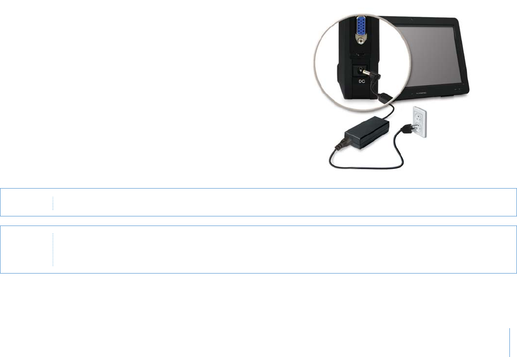
Connecting the Power Cord
Plug the power cord into the AC power receptacle on the back panel
and then plug the other end of the power cord into an appropriately
grounded electrical outlet.
CAUTION 4OPROTECTYOURCOMPUTERANDOTHERDEVICESDURINGALIGHTNINGSTORMORWHENITISLEFTUNATTENDEDANDUNUSEDFOR
LONGPERIODSOFTIMEUNPLUGTHECOMPUTERANDOTHERDEVICESFROMTHEWALLOUTLETANDDISCONNECTTHEANTENNAORCABLE
SYSTEM4HISWILLHELPTOPREVENTDAMAGETOTHECOMPUTERANDOTHERDEVICESDUETOLIGHTNINGANDPOWERLINESURGES
Warning 4OAVOIDRECEIVINGANELECTRICSHOCKBESURETOPLUGTHECORDINTOTHESYSTEMBEFOREPLUGGINGITINTOTHEWALLSOCKET
2-5
Chapter 2 Setting Up Your System
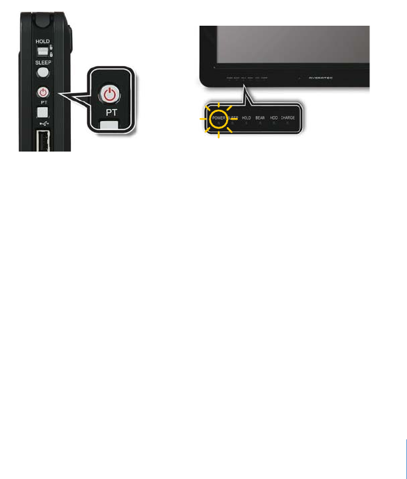
Turning On Your System
To turn on your system, press the power button.
2-6
Chapter 2 Setting Up Your System
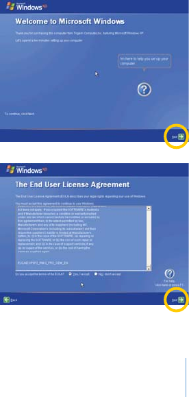
Setting Up Windows XP for the First Time
If you are about to use the system for the first time, you must go through the Windows XP user registration process after starting up.
For details on the user registration procedure, please refer to the following. (Some details may vary depending on the system model.
However, this will not affect your ability to use your system.)
1
.After you press the power button, the start screen for
Microsoft Windows will appear. To start Windows XP,
please click Next.
2
.After reading "The End User License Agreement" thatis
displayed on the screen, select "Yes, I accept" and then
click Next.
2-7
Chapter 2 Setting Up Your System
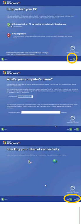
3
.After selecting "Help protect my PC by turning on
Automatic Updates now," you should click Next.
4
.Now you must specify the name and description of your
computer, and then click Next. If you don’t want to specify
these at this time, simply click Skip.
5
.After selecting the appropriate method for internet
connection, click Next. If you want to establish a
connection later, then click Skip. (The dialogue box that
asks, "How do you want to connect to the internet?"
may not appear, depending on your model type.)
2-8
Chapter 2 Setting Up Your System
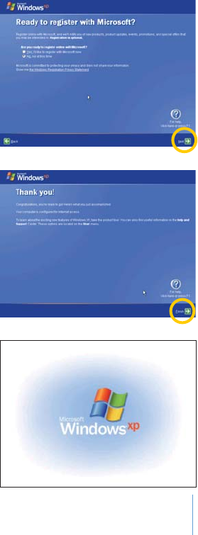
6
.A dialogue box will appear, asking you "Ready to register with
Microsoft?" Select "No, not at this time." and then click Next.
7
.When a dialogue box saying "Thank you!" appears, click Finish.
8
.The Windows XP start will appear.
2-9
Chapter 2 Setting Up Your System
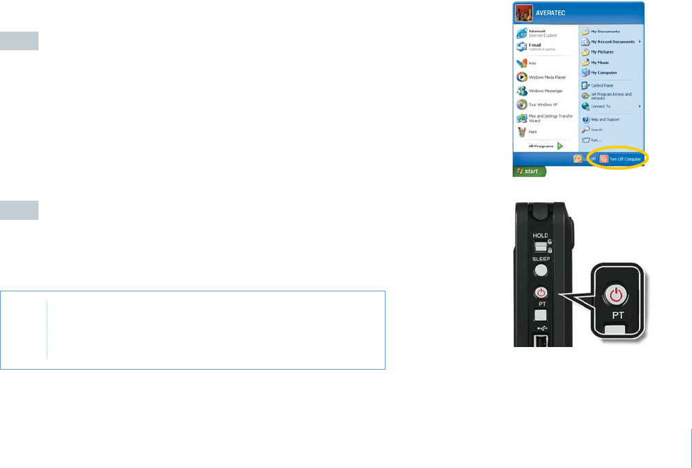
Turning Off Your System
To turn off your system, follow the below:
Case 1
Case 2
Click the Shut Down button
Click Start > Shut Down. The computer will shut down
automatically.
Press the power button on the right side of the system
Press the power button once and let go. The PC will automatically
attempt to close any running applications and shut down.
Note )FTHESYSTEMISOPERATINGABNORMALLYYOUCANREBOOTTHE
SYSTEMBYPRESSINGANDHOLDINGDOWNTHEPOWERBUTTONUNTIL
THESYSTEMTURNSOFF0RESSTHEPOWERBUTTONAGAINONCETO
RESTARTTHESYSTEM

2-10
Chapter 2 Setting Up Your System
Case 3
Power saving mode
You can enter into the power saving mode by pressing the SLEEP
button on the right side of your system or by setting the Windows XP.
This mode saves your session and puts the computer in a lower-
power state so that you can quickly resume working.

3
Chapter 3 Using Your System
Using Your System
Chapter
3
3-1
Chapter 3 Using Your System
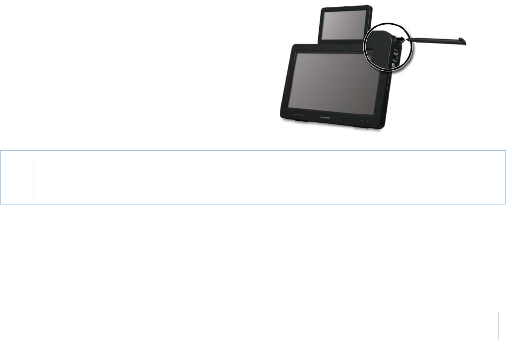
Using the Stylus Pen
You can use the touchscreen with your fingers or the stylus pen.
Pull out the Stylus Pen
1
.Pull out the stylus pen from the slot located on the upper
right side of your system.
2
.After using the stylus pen, replace it in the slot again.
Note
p
7ITHTHESTYLUSPENYOUCANDIRECTLYPRESSONTOTHE,#$SCREENINSTEADOFUSINGAMOUSE
p
/NLYOPERATETHEPRODUCTWITHTHESTYLUSPENORFINGERS4HE,#$MAYBEDAMAGEDIFAPOINTEDORSHARPOBJECTISUSED
p
&ORLONGTERMUSEITISRECOMMENDEDTOCONNECTAMOUSE
3-2
Chapter 3 Using Your System
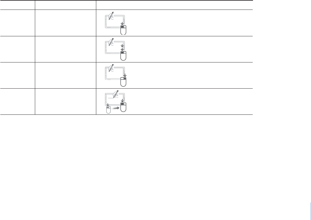
Functions of Stylus Pen
Touchscreen Calibration
You should calibrate the touchscreen:
t When you use the system for the first time
t When you can’t control the pen pointer
t When the pen is not accurate
Click
Double click
Right click
Drag
One touch
Two touches
Keep pressing
Drawing
Press an item once with the pen to choose it.
Press an item twice with the pen to choose it.
Press and hold the touchscreen with the pen
about 3 seconds, then a pop-up menu will appear.
Put the pen on an item and drag it to where
you want.
Mouse Stylus Pen Operation Function
3-3
Chapter 3 Using Your System
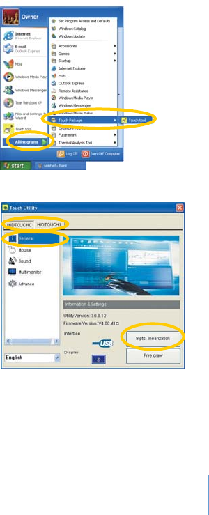
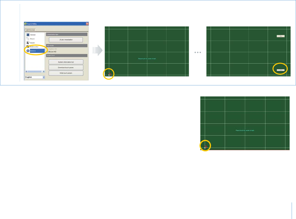
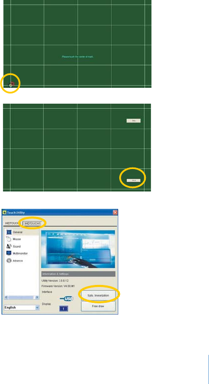
To calibrate the touchscreen, follow these steps:
1
.Press Start > All Programs > Touch Package > Touch tool.
2
.Select the LCD tab that you want to calibrate and press the 9 pts.
Linearization button in the General menu. (The HIDTOUCH0 tab
is for the secondary LCD and HIDTOUCH1 is for the primary LCD.)
3-4
Chapter 3 Using Your System
Note &ORMOREACCURATECALIBRATIONYOUCANCHANGETHEPOINTSFROMTO4OCHANGETHEPOINTSCHOOSETHEAdvanceTAB
ANDPRESSTHE25 pts. linearization BUTTON
3
.To calibrate the touchscreen, follow the message on the screen.
4
.When you nish the calibration, press the Save button to save the setting value.
3-5
Chapter 3 Using Your System
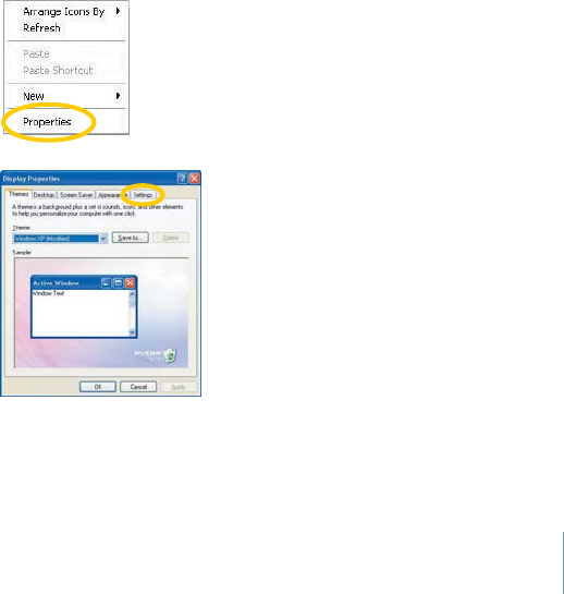
Secondary LCD Pivot Calibration
The secondary LCD supports the screen pivot and touch pivot. You can calibrate the touch pivot when it is not working.
To calibrate, follow these steps:
1
.Press and hold the empty desktop with the stylus pen about 3 seconds.
2
.The pop-up menu will appear.
3
.Choose the Properties menu.
4
.When the Display Properties window appears,
select the Settings tab.
3-6
Chapter 3 Using Your System
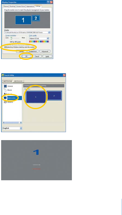
5
.Click the secondary LCD icon, check the "Extend
my Windows desktop onto this monitor."
option, and click OK.
8
.Press the primary LCD to align.
6
.Click Start > All Programs > Touch Package >
Touch tool.
7
.Select the Multimonitor menu and the primary
LCD icon on the Displays area.
3-7
Chapter 3 Using Your System
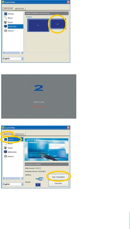
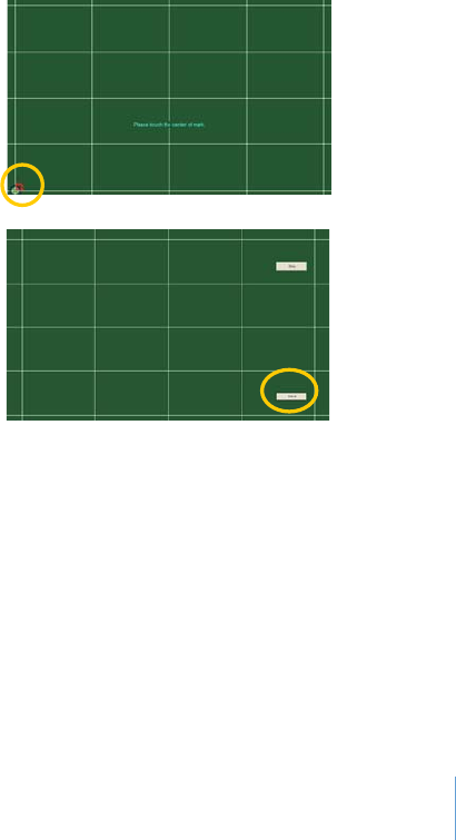
9
.Select the secondary LCD icon on the Displays area.
11
.Select the HIDTOUCH0 tab, the General menu,
and 9 pts. linearization.
10
.Press the secondary LCD to align.
3-8
Chapter 3 Using Your System
12
.To calibrate the secondary LCD, follow the messages
on the screen.
14
.Select the HIDTOUCH1 tab and 9 pts.
linearization.
13
.If you nish the calibration, select the Save
button.
3-9
Chapter 3 Using Your System
15
.To calibrate the primary LCD, follow the messages on
the screen.
17
.To reboot your system, click Start > Turn O Computer, and select the Turn O button.
16
.If you nish the calibration, select the Save
button.
3-10
Chapter 3 Using Your System
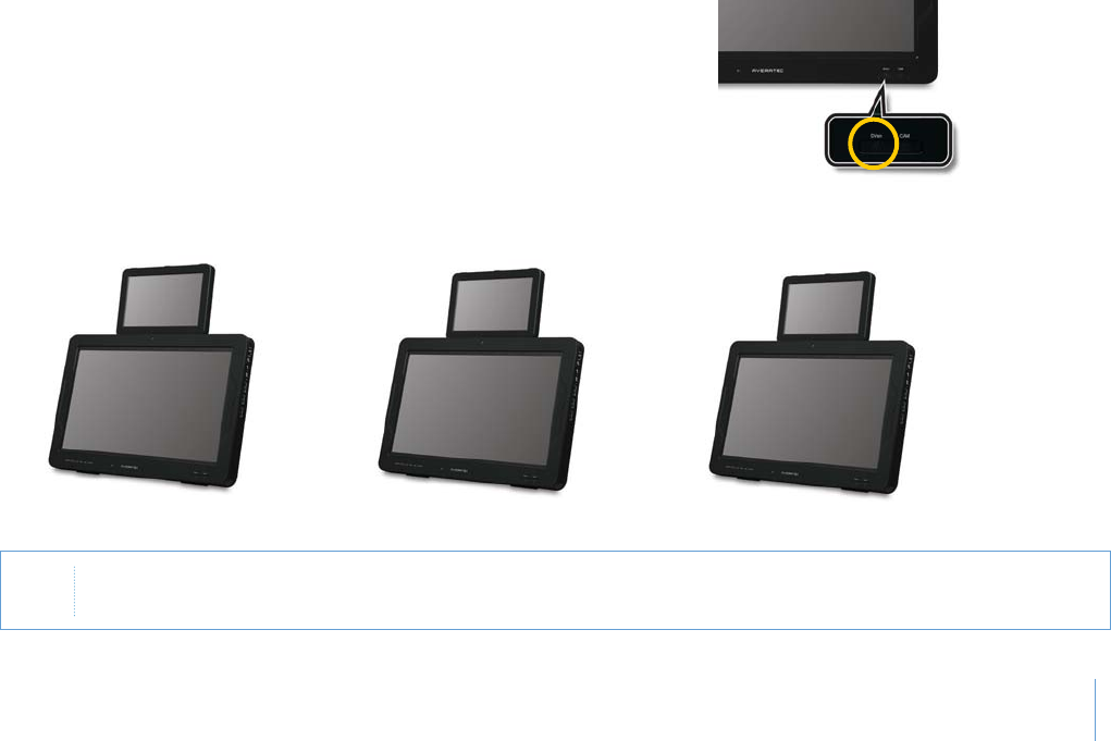
Using the DVsn Button
You can change the display mode by pressing the DVsn button
There are 3 display modes available: Clone mode, Extended mode, and Switching mode.
A
A
B
A
A
B
# L O N E M O D E D E F A U L T ExtendedMODE 3WITCHINGMODE
Note
7HENYOUPRESSTHE
DVsn
BUTTONTHE
DVsn Control
WINDOWTHEAUTOMATICALLYAPPEARSONTHESCREEN&ORMORE
INFORMATIONREFERTO5SINGTHE$6SNAND04#ONTROL0ROGRAM
3-11
Chapter 3 Using Your System
Special Function Buttons
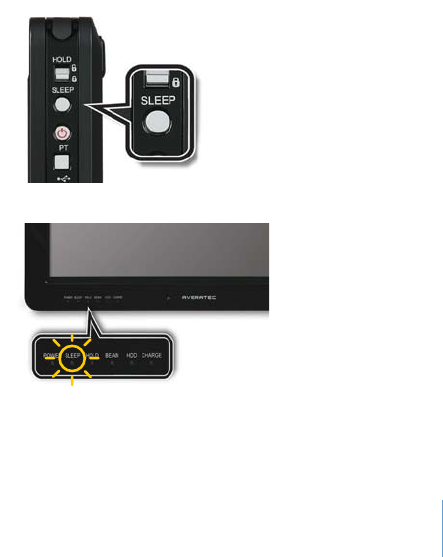
There are two special buttons (SLEEP and PT) on the right side of your system.
SLEEP Button
To enter into the power saving (stand-by) mode, follow these steps:
1
.Press the SLEEP button on the right side of the front panel.
2
.Your system enters into the power saving mode
and the SLEEP led is light on.
3
.Press the Power or PT button to resume from the
power saving mode.
3-12
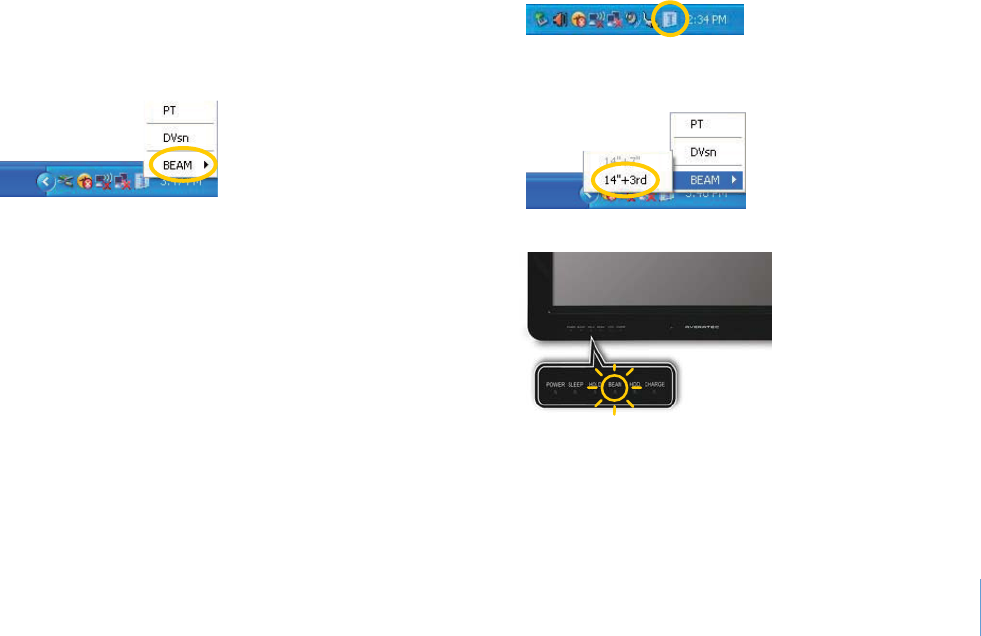
Chapter 3 Using Your System
Note 7HENYOUCONNECTTHEEXTERNALDISPLAYDEVICEANDSETTHEBEAM ControlOPTIONTO14"+3rdTHE BEAMLEDLIGHTWILLBE
ON)FYOUCONNECTANEXTERNALDISPLAYDEVICETHESECONDARY,#$WILLNOTBEDISPLAYED
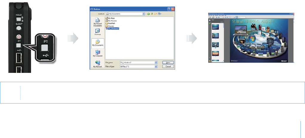
PT Button
You can see the presentation file through the secondary LCD or the connected external display device by pressing the PT button.
1
.To prepare the presentation, reserve the le that you want to present. To reserve the le, refer to “Using the DVsn, PT, and
BEAM Control Program.”
2
.Set the secondary LCD for presentation (extended mode or switching mode) or connect the external display device to the
D-sub connector, turn on the connected device, and set the BEAM Control option to 14"+3rd.
3
.Press the PT button on the system.
4
.You can see the reserved presentation le through the secondary LCD or the connected external display device.
3-13
Chapter 3 Using Your System
Using the DVsn, PT, and BEAM Control Program
You can control the functions of the DVsn and PT buttons and the display by using the control program.
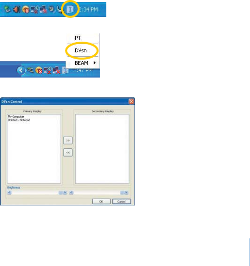
DVsn Control
To control the DVsn function, follow these steps:
1
.Click the AVERATEC Utility icon on the taskbar.
3
.The DVsn Control window appears.
2
.Click DVsn.
3-14
Chapter 3 Using Your System
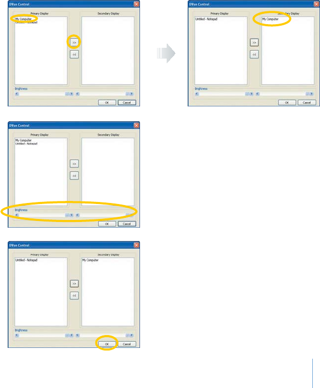
4
.You can choose the primary or
secondary LCD for displaying the
opened window.
5
.You can also control the brightness of
the primary and secondary LCDs by
sliding the control bars.
6
.After nishing the control, click OK.
3-15
Chapter 3 Using Your System
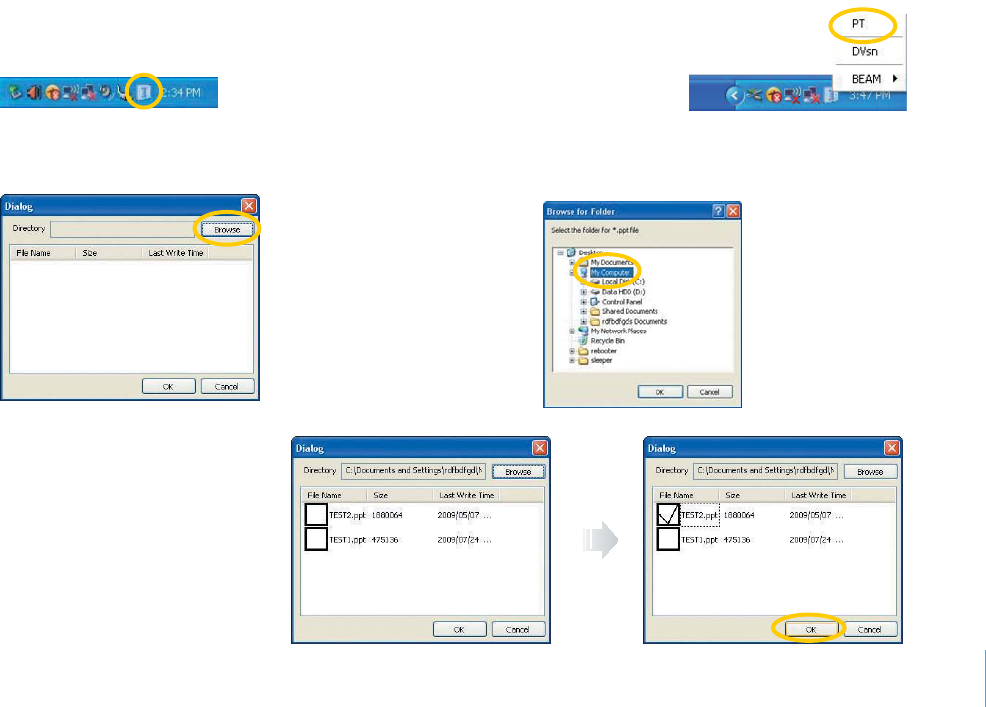
5
.Choose the le for presentation
and click OK.
PT Control
To control the PT function, follow these steps:
2
.Click PT.
1
.Click the
AVERATEC Utility
icon on the taskbar.
3
.When the Dialog window appears, click
the Browse button.
4
.When the Browse for Folder window
appears, select the folder that you want.
3-16
Chapter 3 Using Your System
5
.The BEAM led light will be on and you
can see the screen through the connected
external display device.
BEAM Control
To control the external display device, follow these steps:
1
.Connect an external display device to your system and turn it on.
2
.Click the
AVERATEC Utility
icon on the taskbar.
3
.Click BEAM.
4
.Select the 14”+3rd menu for the external
display device.
3-17
Chapter 3 Using Your System
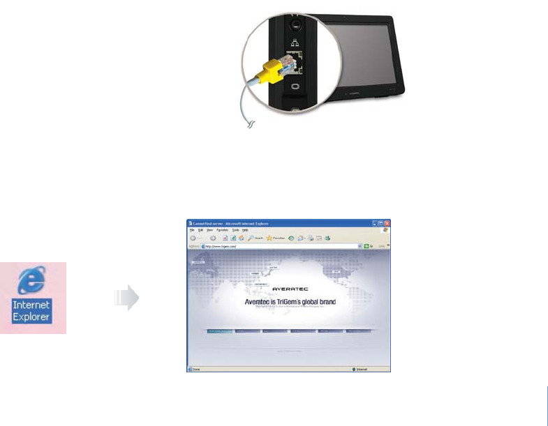
Connecting to the Internet
You can use the Internet by connecting to a wired or wireless network that is available to you.
Using the Wired LAN
To use the wired LAN, follow these steps:
1
.Connect a LAN cable to the LAN connector as shown
in the gure.
2
.Congure the communication settings for the system based on your communication environment. When connecting to the
Internet via an Internet service provider, contact the service provider for more information on required communication settings.
3
.Launch Internet Explorer or other communication software.
3-18
Chapter 3 Using Your System
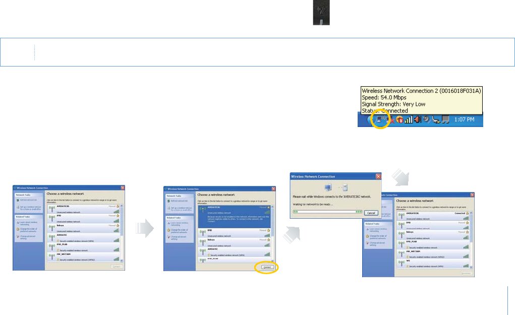
Using the Wireless LAN
To use a wireless network in an office environment where APs (Access Points) are installed, see the following instructions. (The
example used here explains how to use the basic Windows configuration features to configure the system. You can also use the
program that comes with the wireless LAN card to configure the network.)
2
.Click the wireless network connection icon and the program of Wireless
Network Connection will be launched.
1
.Select the WL LAN switch to ON position to turn on the wireless LAN
function. When wireless LAN is enabled, the Wireless LAN LED lights.
Note 4HECONNECTIONMESSAGEWILLAPPEARONTASKBARWHENTHEPOSSIBLEWIRELESS,!.CONNECTIONISDETECTED
3
.Select a wireless network from the list that appears, and then click Connect button. If the network you is security enabled,
the program will ask you to type "Network key."
3-19
Chapter 3 Using Your System
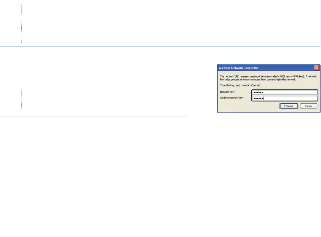
4
.Type Network key and Conrm network key, click Connect to connect the
wireless LAN.
Note
p
#LICKRefresh network listIFTHEREISNOWIRELESSNETWORKINTHELIST
p
)FYOURNETWORKISONETHATSUPPORTS7IRELESS0ROVISIONING3ERVICESYOUMIGHTBEASKEDTODOWNLOADADDITIONALFILES
THATWILLALLOWYOURNOTEBOOKTOCONNECTTOTHENETWORK
p
)FYOUCONNECTTOAUNSECUREDWIRELESSNETWORKTHEWARNINGMESSAGEWILLAPPEAR#LICKConnecTTOCONNECTORCLICK
Cancel TOQUITTHEDIALOGBOX!FTERSETTINGUPTHESECURITYCONNECTTHEWIRELESS,!.AGAIN
Note )FTHENETWORKKEYISAUTOMATICALLYPROVIDEDBYTHENETWORKTHE
CONNECTIONWILLBEMADEAUTOMATICALLYANDTHEPROGRAMWILLNOT
REQUESTYOUTYPETHENETWORKKEY
3-20
Chapter 3 Using Your System
Using the Battery
Installing the Battery
Insert the battery into the battery slot.
Removing the Battery
1
.Turn o the system.
2
.Push and hold the battery release button
and remove the battery.
Push and hold
1
2
3-21
Chapter 3 Using Your System
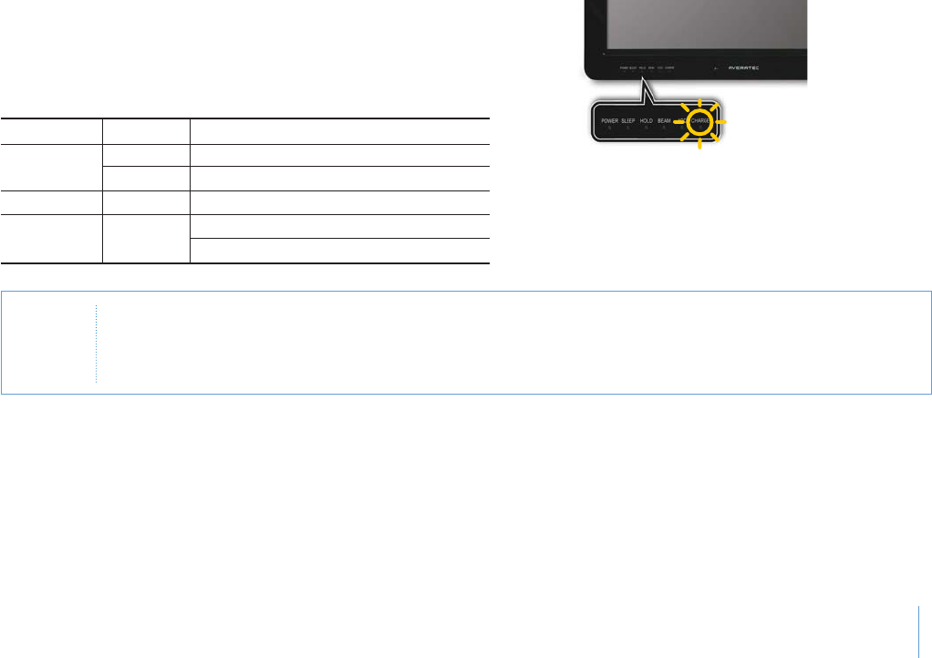
Charging the Battery
The battery pack is automatically charged when you connect the
AC adapter to the system. You can check the battery status by the
color of the CHARGE LED indicator.
LED color Status Description
Orange On Charging battery
Blinking Battery charge is low
White On Battery is fully charged
Off - Battery is fully charged in the battery mode
No charging in the battery mode
CHARGE LED indicator
CAUTION 7HENTHEBATTERYISLOWYOUMAYNOTBEABLETOBOOTYOURSYSTEMWITHONLYTHEBATTERYPOWER4RYCHARGINGTHE
BATTERYORCONNECTINGTHE!#ADAPTERBEFOREATTEMPTINGTOTURNONYOURSYSTEM)FYOUSEETHELOWBATTERYWARNING
MESSAGEORHEARTHEALARMSOUNDIMMEDIATELYSAVEYOURWORKINGDATAORCONNECTTHE!#ADAPTERBEFORETHESYSTEM
SHUTSDOWNANDTHEDATAISLOST
3-22
Chapter 3 Using Your System
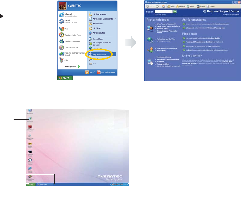
Using the Windows
Help Windows
For Windows XP help, click Start Help and
Support.
Recycle Bin
Taskbar
Start Button Notification
Desktop
Desktop may vary differently on the software installed in your system with different or additional shortcuts.
3-23
Chapter 3 Using Your System
Recycle Bin
Used for storing deleted files in case you want to recover and save it in your system. The files will only be deleted from the Recycle
Bin permanently only if you empty it by right clicking your mouse and selecting "Empty Recycle Bin."
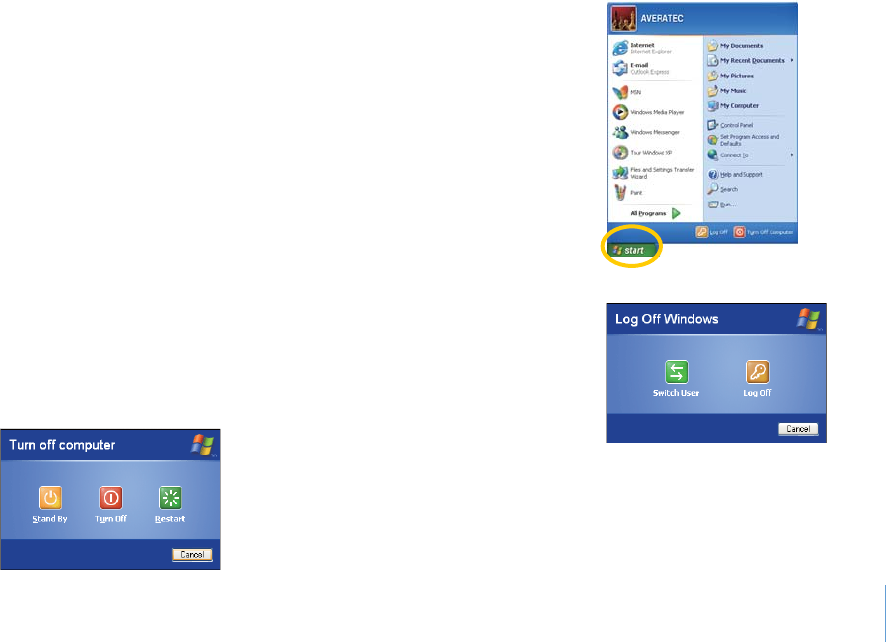
Start Button
Allows easy access to all Windows programs.
The Start menu allows you to adapt and show the programs used
most frequently.
Log Off will enable the current user to log off and allows a new user to log on.
Turn Off Computer allows you to Turn off, Restart, or enter
Stand By mode for power saving purposes.
3-24
Chapter 3 Using Your System
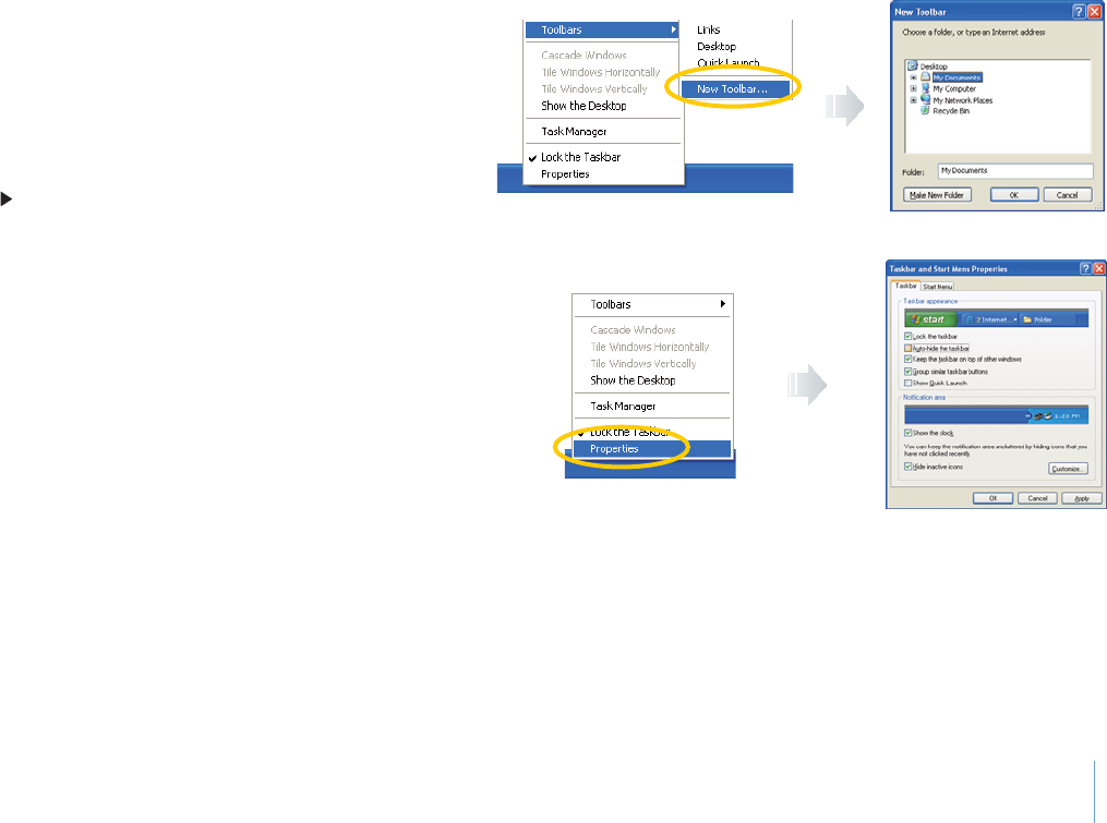
Taskbar
When you open a program, its icon is displayed at
the taskbar for you to conveniently move between
programs by clicking the relevant button.
To add or remove toolbars from the taskbar: right
click an empty spot on the taskbar, select Toolbars
New Toolbar.
Notification
The icons that appear here are for quick access to
some programs and computer functions that you
frequently used. To prevent Windows XP from
hiding icons:
From an empty spot on the Taskbar, right click
your mouse and select the Properties, remove
the checked mark on the Auto-hide the taskbar.
3-25
Chapter 3 Using Your System
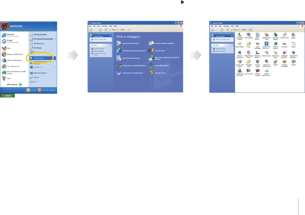
Control Panel
It is in this area that you can change how Windows looks and works. Click Start Control Panel.
There are two interfaces - Classic View and Category View.

3-26
Chapter 3 Using Your System
Using the HOLD Switch
You can lock all functions of your system by using the HOLD
switch. Move the HOLD switch to the locked position to lock
all functions of your system. To unlock the system, switch to
the unlocked position again.
In the lock mode, the following functions will not work:
t Primary and secondary LCD touch panels
t Sleep button
t Power button
t PT button
3YSTEM5NLOCK
3YSTEM,OCK

4
Chapter 4 Using the Multimedia Features
Using the Multimedia Features
Chapter
4
Chapter 4 Using the Multimedia Features
4-1
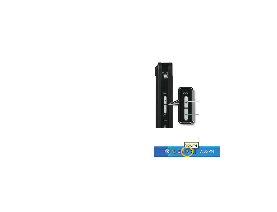
Adjusting the Speaker Volume
Your system has built-in speakers on the left and right sides of the LCD panel. You can adjust the volume by pressing the volume
adjustment buttons located on the left side of the LCD panel and / or by using the volume control feature in Windows XP.
Volume button (Up)
Volume button (Down)
Volume Buttons
To adjust the volume level, use the volume up
and down buttons on the left side of your
system.
Volume Control Program
You may also change the volume by using the vertical slider
which appears after clicking the volume icon on the work
presentation bar.
4-2
Chapter 4 Using the Multimedia Features
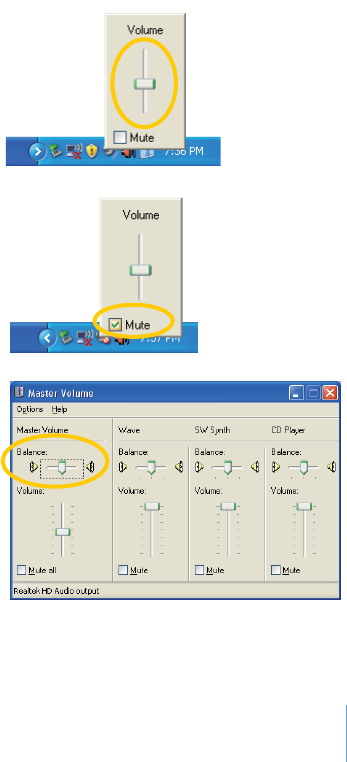
1
.Increase the sound by moving the slider up.
2
.Decrease the sound by moving the slider down.
4
.Click the volume icon twice to see master volume window.
5
.Here, you may separately modify the items you want.
3
.Silence the system by clicking Mute.
Chapter 4 Using the Multimedia Features
4-3
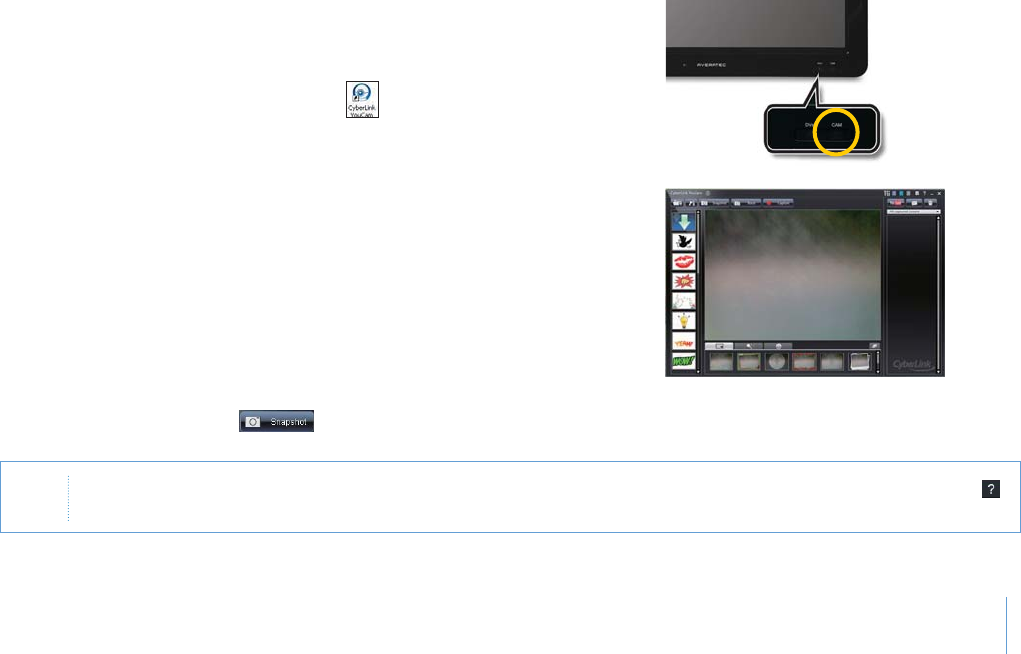
Using the Webcam
Using the built-in webcam, you can take photos and chat with your friends.
Take photos
To take photos, follow the next steps:
1
.Double click the CyberLink YouCam icon( ) on the desktop,
or press the CAM button that is located on lower-front side of
the system.
2
. T h e CyberLink YouCam will run and a green light on the
webcam LED indicates your PC is ready to take photos.
3
.Click the Snapshot button( ) on the CyberLink YouCam screen.
Note &ORMOREINFORMATIONPLEASEREFERTOTHE(ELP3ECTIONOFTHEPROGRAM9OUCANACCESS(ELPBYCLICKINGTHEHELPBUTTON
ONTHEUPPERRIGHTSIDEOFTHESCREEN
4-4
Chapter 4 Using the Multimedia Features
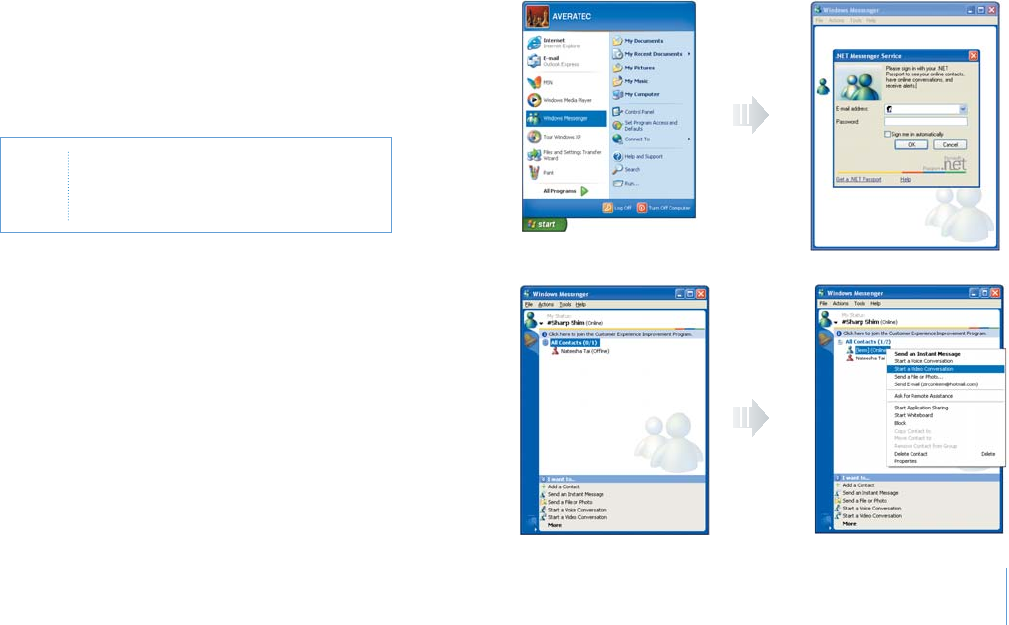
Video chatting
To chat with video, both your system and the system of the person you want to chat with must have a web camera or a CCD cam
nstalled. You also need to download and install a messenger program. The screen that you will see varies depending on the type of
the messenger program you're using.
1
.Run the messenger program to register your
email address. When the messenger is ready.
Click Start > Windows Messenger.Select
Sign in.
Note 4HISISANEXAMPLEUSING-ICROSOFTS
-3.-ESSENGER/THERMESSENGER
APPLICATIONSMAYVARY
2
. Right-click on your chat partner and
then select Start a Video Conversation,
as illustrated below.

Chapter 4 Using the Multimedia Features
4-5
3
.Now you're ready to start video chatting.
Note )FTHEWEBCAMERASETTINGISNOTCONFIGUREDYOUWILLSEETHEBELOWSCREEN
2UNTHEWIZARDTOSETUPTHEWEBCAMBYFOLLOWINGTHEMESSAGEONTHESCREEN

5
Chapter 5 System SETUP (BIOS)
System SETUP (BIOS)
Chapter
5

5-1
Chapter 5 System SETUP (BIOS)
For System Setup, change only the items that you need. Note that incorrect manipulation of Setup items could result in a system
malfunction.
Entering Setup
After powering on the system, press <Del> to enter the System Setup screen.
BIOS Action Keys
Leaves a sub-menu to return to the previous menu OR exits the BIOS setup while saving changes.
Shows the Sub Menu
ESC Exit
Enter Select
Function Key Command Description
Shows the Help ScreenF1 General Help
Saves default settingF9 Default Setting
Saves changes and reboots the computer.F10 Save and Exit
Selects the next field.<Tab> Select a field
Selects the next item.Select an item
-, + value Selects the next value within a field.
5-2
Chapter 5 System SETUP (BIOS)
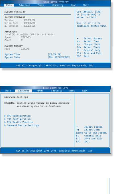
System Setup Options
Main Menu
Advanced Menu
5-3
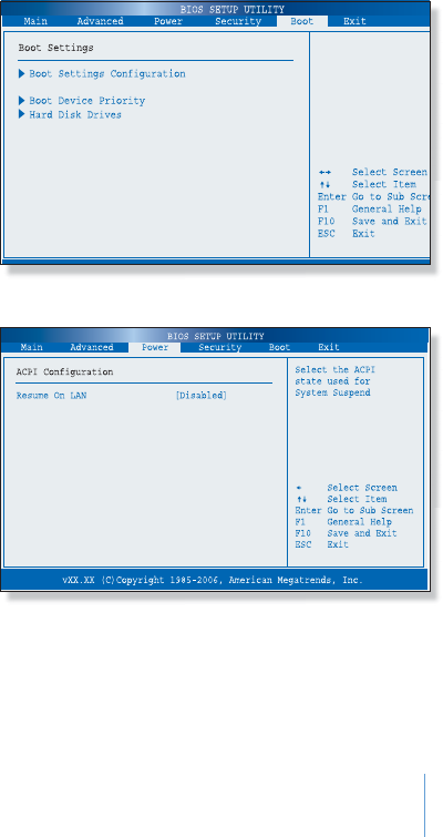
Chapter 5 System SETUP (BIOS)
Boot Menu
Power Menu
5-4
Chapter 5 System SETUP (BIOS)
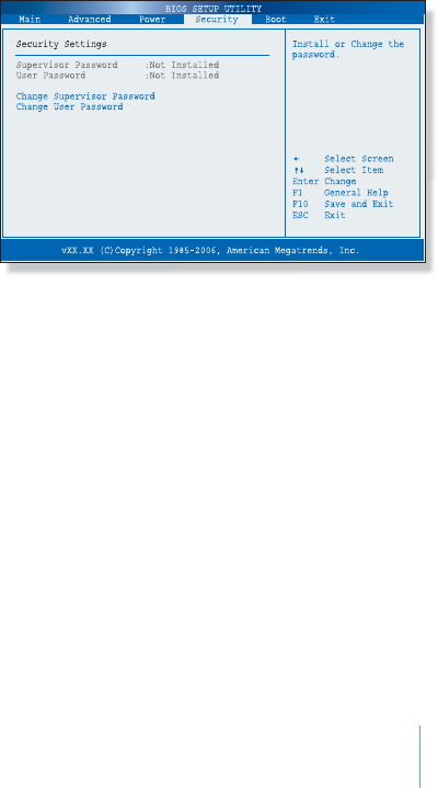
Supervisor Password
Shows the setup status of the Supervisor Password: Installed, if a Supervisor Password is set, or Not Installed.
User Password
Shows the setup status of the User Password: Installed, if a User Password is set, or Not Installed.
Change Supervisor Password
Setting up a password helps you prevent unauthorized users from accessing the system. The system does not come with a password
enabled. A password can have up to six alphanumeric characters and/or numbers.
Security Menu
Sets up a password to prevent any unauthorized users from
accessing the system.

5-5
Chapter 5 System SETUP (BIOS)
Set up Supervisor Password
1
.On the initial System Setup screen, Go to Change Supervisor Password, and then press Enter.
2
.On the following screen, enter the password and then press Enter.
Then enter the same password again and press Enter.
Enter New Password
Confirm New Password
3
.If you entered the correct password, the following window will appear. Press Enter.
This completes setting up a password.
Password installed
[OK]
The Supervisor Password is at a higher level than the User Password.
5-6
Chapter 5 System SETUP (BIOS)
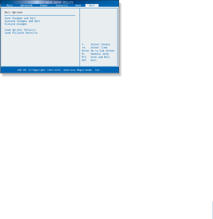
Save Changes and Exit
Save the changes you have made and exit the utility.
Discard Changes and Exit
Exit the utility without saving the changes you have made.
Discard Changes
Abandon your changes and reload the prior configuration.
Load Optimal Defaults
Select this item to load the default settings for optimal system performance.
Exit Menu

Specifications
Appendix
A

A-1
Appendix A Specifications
Product Specifications
Product specifications may be different according to models. Please refer to the catalogue offered when you purchase the product.
Intel® Atom Z520
Microsoft Windows XP Edition SP3
Intel® US15W
1GB SO-DIMM, DDR2 533MHz
120GB / 160GB / 250GB / 60GB / 80GB
- S3 CHROME 530 ULP
- 256MB External Graphics Memory
- Primary LCD : 14.0" Wide TFT-LCD with LED Backlight Design (1366×768)
- Secondary LCD : 7.0" Wide TFT-LCD with LED Backlight Design (1024×600)
High Definition Audio
1000 BASE-TX/100BASE-TX/10BASE-T
802.11 b/g/n
Touch Screen
1.3M / USB2.0
Stereo Speaker (0.5W+0.5W)
65W, AC Adapter, 100 ~ 240V, 20V / 2.25A
- Size: 362.23 mm (W) X 245.6 mm (H) X 32.1 mm (D) (Secondary LCD Folding)
362.23 mm (W) X 370.3 mm (H) X 32.1 mm (D) (Secondary LCD Unfolding)
- Weight: 2.5 kg
CPU
OS
Chipeset
Memory
HDD
Graphic System
Display
Sound System
LAN
Wireless LAN
Pointing device
Camera
Speaker
Power Supply
System Size and Weight
Feature Specifications

A-2
Appendix A Specifications
- Right: HOLD Switch, Buttons (Sleep, Power, and PT), USB 2.0 x 3
- Left: WLAN On/Off Switch, Volume Up/Down Buttons, Headphone Jack, RJ-45 Jack, D-Sub 15pin
Connector, Power Jack
- Front: Webcam, Internal MIC, Stereo Speakers, Touch Buttons (DVsn and CAM)
LED Status Indicators (POWER, SLEEP, HOLD, BEAM, HDD, and CHARGER)
- Touch Screen
Lithium ion Battery (11.1V, 3400mAh)
Input 100-240V, 50/60Hz
Interface
Battery
AC adapter
Temperature
- Operation: +5 oC to 35 oC
- Storage: -10 oC to 55 oC
Humidity
- Operation: 30 % to 80 % (noncondensing)
- Storage: 20 % to 90 %
Environmental Requirement
Feature Specifications