Users Manual
0
TriMarkCorporation
Generation3EAskSystem
FCCgeneralinformationdoc
Contents
37843‐IOModule.........................................................................................................................................2
PinLayout..................................................................................................................................................2
J11 – Baseboard 12-pin.........................................................................................................................2
J13 – Baseboard 14-pin........................................................................................................................2
J1 – Programmable Inputs & Relay Outputs Group 1......................................................................2
J2 – Key Switch & Relay Outputs Group 2........................................................................................3
J3 – External Relay Drivers.................................................................................................................3
J4 – Relay Outputs Group 3................................................................................................................4
J5 – Relay Outputs 4............................................................................................................................4
J14 - JTAG Connector..........................................................................................................................4
GeneralSpecifications...............................................................................................................................4
IOModuleFCCversion..............................................................................................................................6
Wiringdiagram..........................................................................................................................................7
FCCruleandregulation.............................................................................................................................8
ThisdevicecomplieswithPart15oftheFCCRules.Operationis subjecttothefollowing two
conditions:
(1) This device may not cause harmful interference, and (2) This device must accept any
interferencereceived,includinginterferencethatmaycauseundesiredoperation.
Lemanueld'utilisationdesappareilsradioexemptsdelicencedoitcontenirl'énoncéquisuit,ou
l'équivalent,àunendroitbienenvueet/ousurlesappareils:
1
LeprésentappareilestconformeauxCNRd'IndustrieCanadaapplicablesauxappareilsradioexemptsde
licence.L'exploitationestautoriséeauxdeuxconditionssuivantes:(1)l'appareilnedoitpasproduirede
brouillage,et(2)l'utilisateurdel'appareildoitacceptertoutbrouillageradioélectriquesubi,mêmesile
brouillageestsusceptibled'encompromettrelefonctionnement.

2
37843‐IOModule
PinLayout
J11 – Baseboard 12-pin
Error! Objects cannot be created from editing field codes.
Pin Signal Name Input/
Output
J11.1
V
IN Input
J11.2 PROG_IN_3 Input (+)
J11.3 PROG_OUT_2 Output
J11.4 PROG_OUT_1 Output
J11.5 PROG_IN_1 Input (+)
J11.6 LF_ANT125_OUT_1 Output
J11.7 RELAY_20A_1 Output
J11.8 RELAY
_
20A_2 Output
J11.9 CANL In/Out
J11.10 CANH In/Out
J11.11 GND
J11.12 LF_ANT125_IN_1 Input
J13 – Baseboard 14-pin
Error! Objects cannot be created from editing field codes.
Pin Signal Name Input/
Output
J13.1 PROG_OUT_4 Output
J13.2 PROG_IN_2 Input (+)
J13.3 PROG_OUT_3 Output
J13.4 LF_ANT125_OUT_3 Output
J13.5 LF_ANT125_OUT_2 Output
J13.6
J13.7
J13.8 12V_REG Output
J13.9 PROG_IN_4 Input (+)
J13.10 GND
J13.11 LF_ANT125_IN_3 Input
J13.12 LF_ANT125_IN_2 Input
J13.13 GND
J13.14 HF_433MHZ_ANT Input
J1 – Programmable Inputs & Relay Outputs Group 1
Error! Objects cannot be created from editing field codes.
Pin Signal Name Input/
Output
J1.1 PROG_IN_101 Input
(
-
)

3
J1.2 PROG_IN_102 Input
(
-
)
J1.3 PROG_IN_103 Input
(
-
)
J1.4 & 16 GND
J1.5 & 17 RELAY_30A_109 Output
J1.6 & 18 RELAY_30A_110 Output
J1.7 & 19
V
IN Input
J1.8 RELAY_20A_111 Output
J1.9 PROG_IN_104 Input
(
-
)
J1.10 PROG_IN_105 Input
(
-
)
J1.11 PROG_IN_106 Input
(
-
)
J1.12 PROG_IN_107 Input
(
-
)
J1.13 PROG_IN_108 Input
(
-
)
J1.14
J1.15
J1.20
J1.21 RELAY_20A_114 Output
J1.22
J1.23 PROG_IN_109 Input
(
-
)
J1.24 RELAY_20A_113 Output
J2 – Key Switch & Relay Outputs Group 2
Error! Objects cannot be created from editing field codes.
Pin Signal Name Input/
Output
J2.1
V
IN Input
J2.2
J2.3
J2.4 KEY_SWITCH_1 /
P_BRAKE_SWITCH
Input
J2.5
J2.6 GND
J2.7 KEY_SWITCH_
COM
J2.8 KEY_SWITCH_2 /
LOCK_SWITCH
Input
J2.9
J2.10 GND
J3 – External Relay Drivers
Error! Objects cannot be created from editing field codes.
Pin Signal Name Input/
Output
J3.1 12V_REG Output
J3.2 PROG_OUT_101 Output
J3.3 PROG_OUT_102 Output
J3.4
J3.5
J3.6 PROG_OUT_105 Output
J3.7 PROG_OUT_106 Output
J3.8
4
J4 – Relay Outputs Group 3
Error! Objects cannot be created from editing field codes.
Pin Signal Name Input/
Output
J4.1 RELAY_20A_102 Output
J4.2 RELAY_20A_101 Output
J4.3 RELAY_20A_104 Output
J4.4 RELAY_20A_103 Output
J4.5 RELAY_20A_105 Output
J4.6 RELAY_20A_106 Output
J5 – Relay Outputs 4
Error! Objects cannot be created from editing field codes.
Pin Signal Name Input/
Output
J5.1 GND Output
J5.2
J5.3 12V_FUSED Output
J5.4
J14 - JTAG Connector
This internal connector is for factory programming and software development.
Pin Signal Description
J14.1 (Unused Pin)
J14.2 PIC_PGC Programmer Cloc
k
J14.3 PIC_PGD Programmer Data
J14.4 GND Circuit Ground
J14.5 +3.3V_SC Internal +3.3V Power
J14.6 PIC_MCL
R
Master Clear
–
reset control
GeneralSpecifications
Input Activated Reaction from Hardware Tests
PROG_IN_1 PROG_OUT_1 activates while PROG_IN_1 is active.
The software also searches for a fob near LF antenna 1 and if a fob is found
RELAY_20A_1 activates for 500 msec.
PROG_IN_2 PROG_OUT_2 activates while PROG_IN_2 is active.
PROG_IN_3 PROG_OUT_3 activates while PROG_IN_3 is active.
PROG_IN_4 PROG_OUT_4 activates while PROG_IN_4 is active.
Fob Button 1 REL
A
Y_20A_2 activates while fob button 1 stays active.
Fob Button 2 RELAY_20A_1 activates while fob button 2 stays active.
Fob Button 3 PROG_OUT_3 activates while fob button 3 is pressed.
Fob Button 4 PROG_OUT_4 activates while fob button 4 is pressed.

5
P
R
OG_IN_101 PROG_OUT_101 activates while PROG_IN_101 is active.
PROG_IN_102 PROG_OUT_102 activates while PROG_IN_102 is active.
PROG_IN_103 RELAY_20A_105 activates while PROG_IN_103 is active.
PROG_IN_104 RELAY_20A_106 activates while PROG_IN_104 is active.
PROG_IN_105 PROG_OUT_105 activates while PROG_IN_105 is active.
PROG_IN_106 PROG_OUT_106 activates while PROG_IN_106 is active.
PROG_IN_108 RELAY_20A_101 activates while PROG_IN_108 is active.
PROG_IN_109 RELAY_20A_102 activates while PROG_IN_109 is active.
KEY_SWITCH_1 RELAY_20A_103 activates while KEY_SWITCH_1 is active.
KEY_SWITCH_2 RELAY_20A_104 activates while KEY_SWITCH_2 is active.
PROG_IN_2 &
PROG_IN_3
When both PROG_IN_2 and PROG_IN_3 are sensed active at the same time, the
factory test software activates each I/O expander relay output for 1 second in the
sequence RELAY_20A_101, 102, … 116.
Toactivateinputs1‐4are12V
Toactivateallotherinputs(100‐200)aregrounds
PowerSupply 6.5Vto16V
Nominal12V
QuiescentCurrent(noload) 311uA
Nominal(load) 2.5mA
OnBoardrelays(active) 30A
Normal(Actuator) 5A
AllANT125arebi‐directional.
6
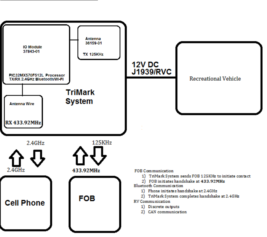
OperatingPrincipals:
OperatingPrincipleofWi‐Fi/Bluetooth:TriMarkbelieveswewillusethisforinformationtransfersuchas
communicationonasmartphone.Thisisafutureproofingaccessory.
Wi-Fi/Bluetooth with modular certificate , FCC ID:XF6-RS9113SB IC:8407A-RS9113SB
IOModuleFCCversion
LFwillconstantlygeneratea125KHzwaveonchannel1aslongasitispluggedin.Donotleaveon
morethan4hoursatatime.Channels2and3usethesamecircuit,butwillnotbeon.Bluetoothwill
beactiveduringtest.
7
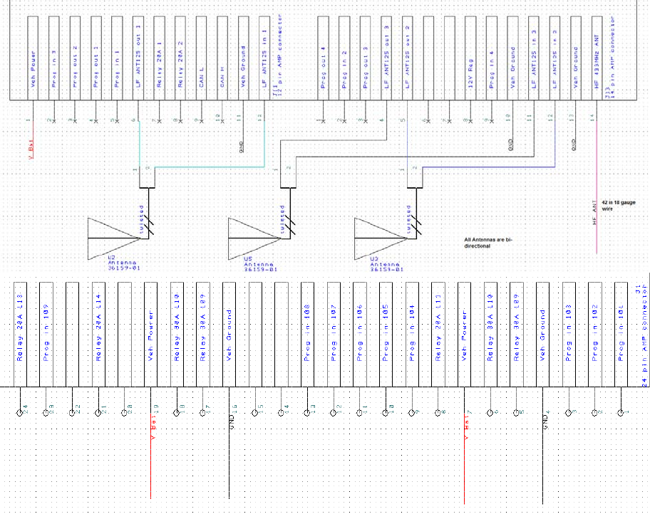
Wiringdiagram
AllotherIOarenotpopulated.
8
FederalCommunicationCommissionInterferenceStatement
This equipment has been tested and found to comply with the limits for a Class B digital device,
pursuant to Part 15 of the FCC Rules. These limits are designed to provide reasonable protection
against harmful interference in a residential installation.
This equipment generates, uses and can radiate radio frequency energy and, if not installed and
used in accordance with the instructions, may cause harmful interference to radio
communications. However, there is no guarantee that interference will not occur in a particular
installation. If this equipment does cause harmful interference to radio or television reception,
which can be determined by turning the equipment off and on, the user is encouraged to try to
correct the interference by one of the following measures:
. Reorient or relocate the receiving antenna.
. Increase the separation between the equipment and receiver.
. Connect the equipment into an outlet on a circuit different from that to which the receiver is
connected.
. Consult the dealer or an experienced radio/TV technician for help.
FCC Caution: To assure continued compliance, any changes or modifications not expressly
approved by the party responsible for compliance could void the user's authority to operate this
equipment. (Example - use only shielded interface cables when connecting to computer or
peripheral devices).
FCC Radiation Exposure Statement
This equipment complies with FCC RF radiation exposure limits set forth for an uncontrolled
environment.
This transmitter must not be co-located or operating in conjunction with any other antenna or
transmitter.
Thisdevicecomplieswithpart15oftheFCCRulesandCanadalicence‐exempt
RSS‐210standard.Operationissubjecttothefollowingtwoconditions:
(1) thisdevicemaynotcauseinterference,and(2)thisdevicemustacceptany
interference,includinginterferencethatmaycauseundesiredoperationofthe
device.
Lemanueld'utilisationdesappareilsradioexemptsdelicencedoitcontenir
l'énoncéquisuit,oul'équivalent,àunendroitbienenvueet/ousurles
appareils:
LeprésentappareilestconformeauxCNRd'IndustrieCanadaapplicablesaux
appareilsradioexemptsdelicence.L'exploitationestautoriséeauxdeux
conditionssuivantes:(1)l'appareilnedoitpasproduiredebrouillage,et(2)
l'utilisateurdel'appareildoitacceptertoutbrouillageradioélectriquesubi,
mêmesilebrouillageestsusceptibled'encompromettrelefonctionnement.