Trilliant Networks CONN Wireless Mesh Wide Area Network CPE User Manual Installation Guide
Trilliant Networks, Inc. Wireless Mesh Wide Area Network CPE Installation Guide
UserManual.wiki
>
Trilliant Networks
>
CONN User Manual
>
Gateway
Contents
1.
Manual Appen B
2.
Manual
3.
Extender
4.
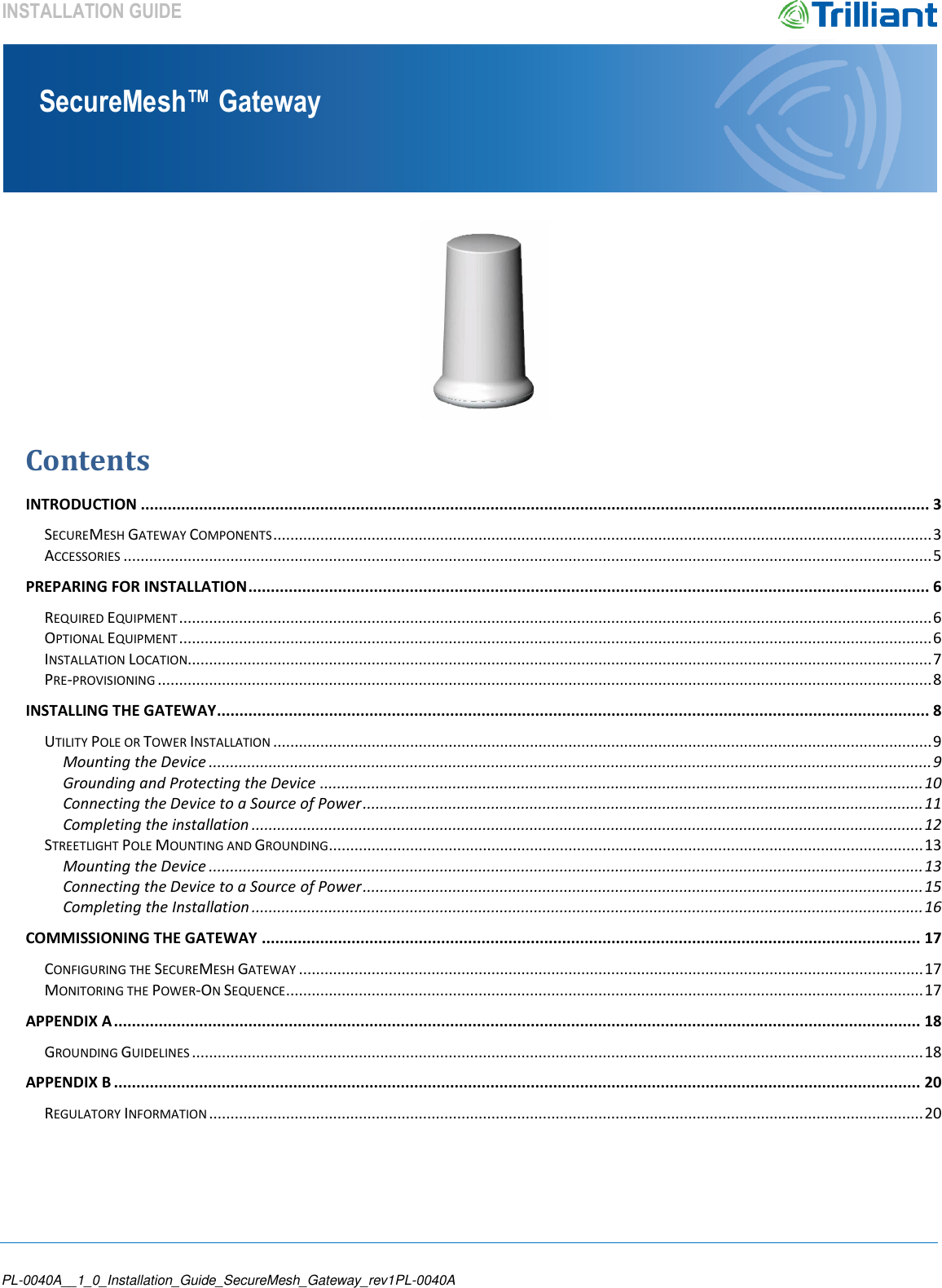
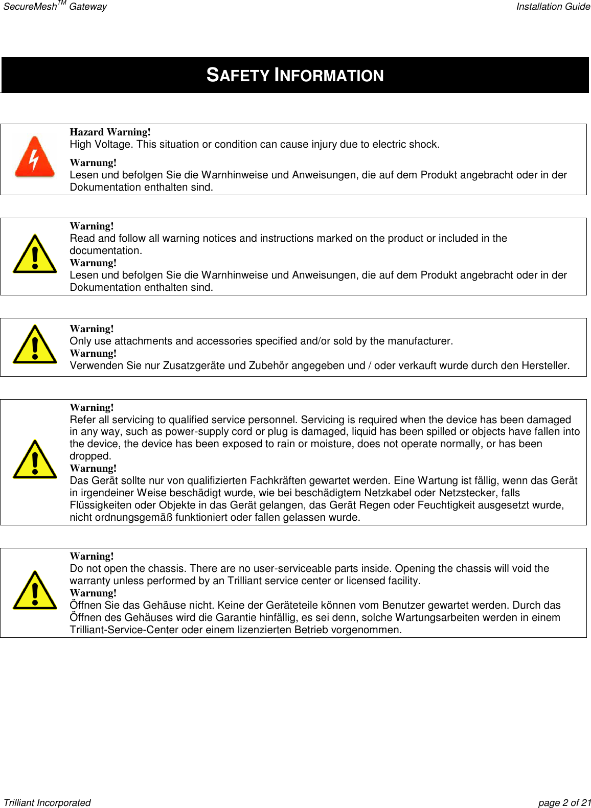
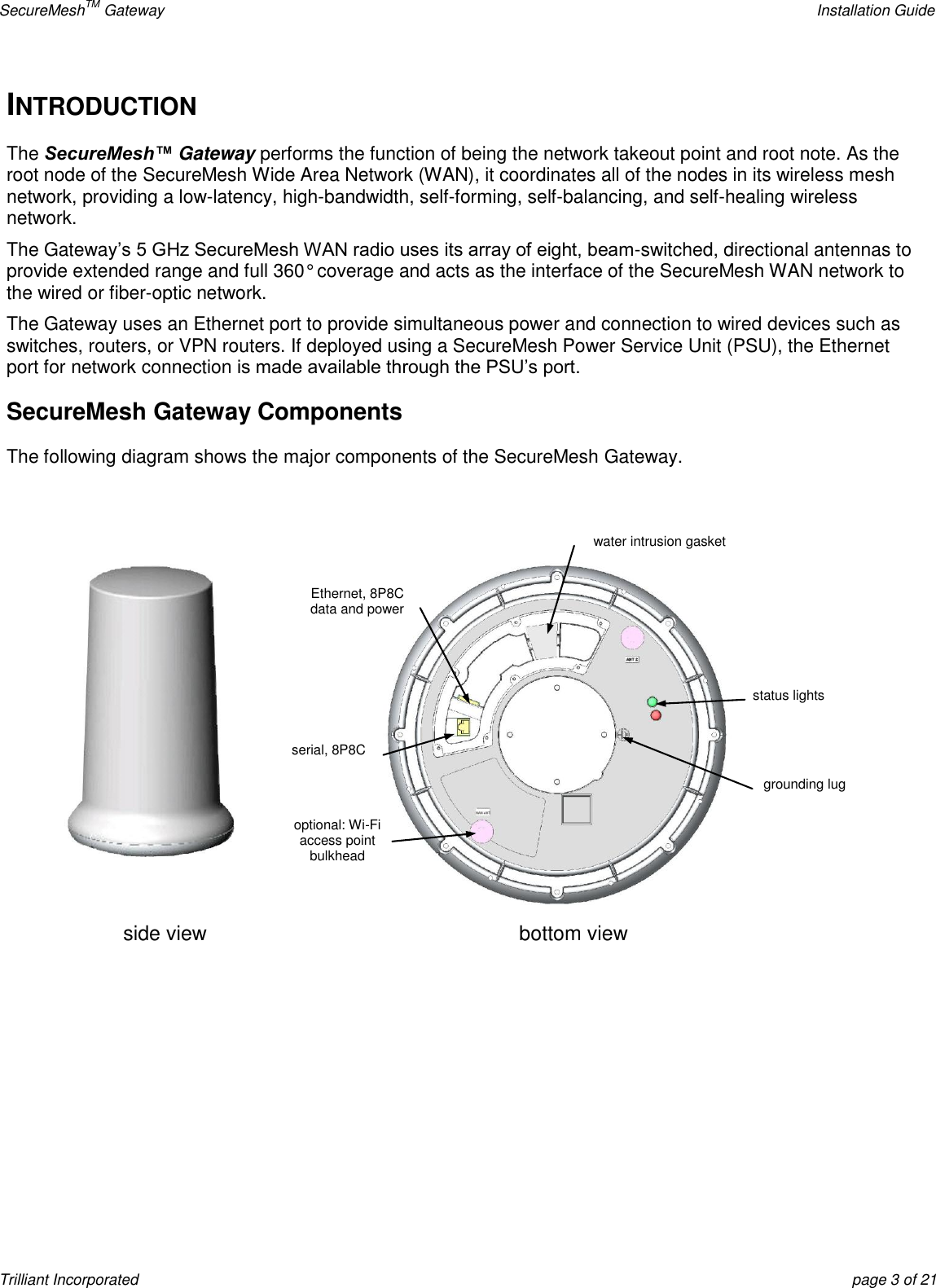
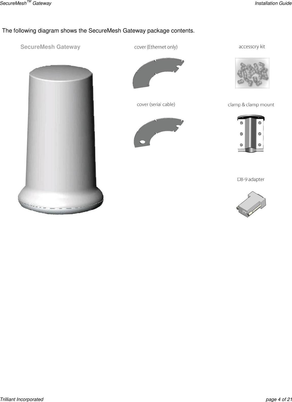
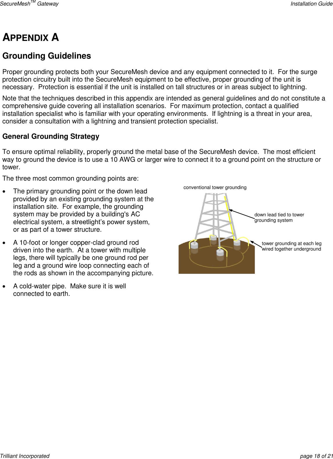
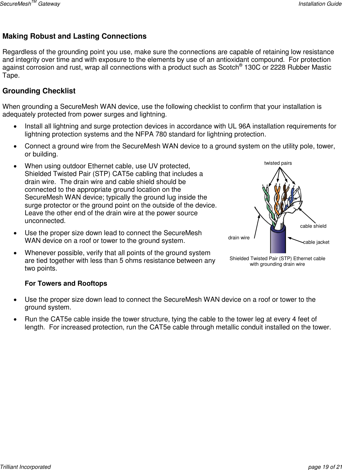
Gateway
5.
Extender Bridge
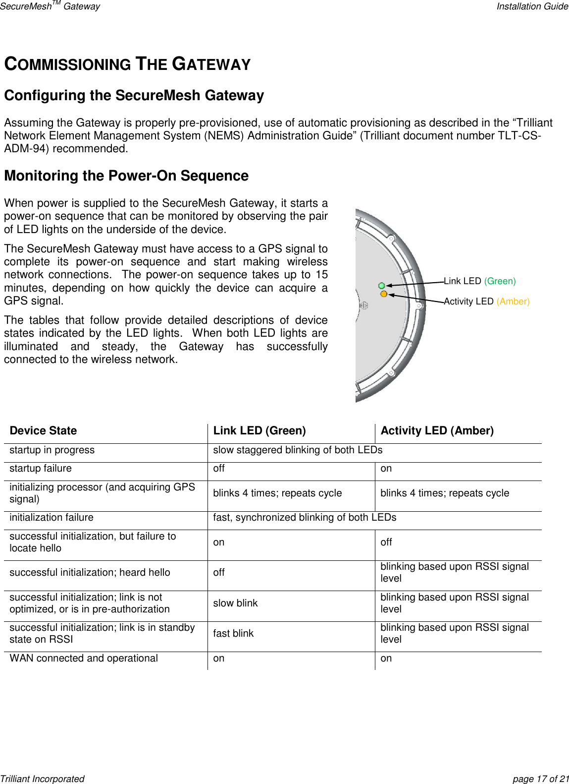
Gateway
Navigation menu
Upload a User Manual
Namespaces
Wiki Guide
HTML
PDF
Info
Views
User Manual
Discussion / Help
Navigation