Trilliant Networks G30FOCUS Wireless Electric Meter User Manual Manual
Trilliant Networks Wireless Electric Meter Manual
Manual
RES-3000-Focus
PA-0129A Rev. 1.0 June 18, 2010 Page 1 of 4
RES-3000-FocusAX
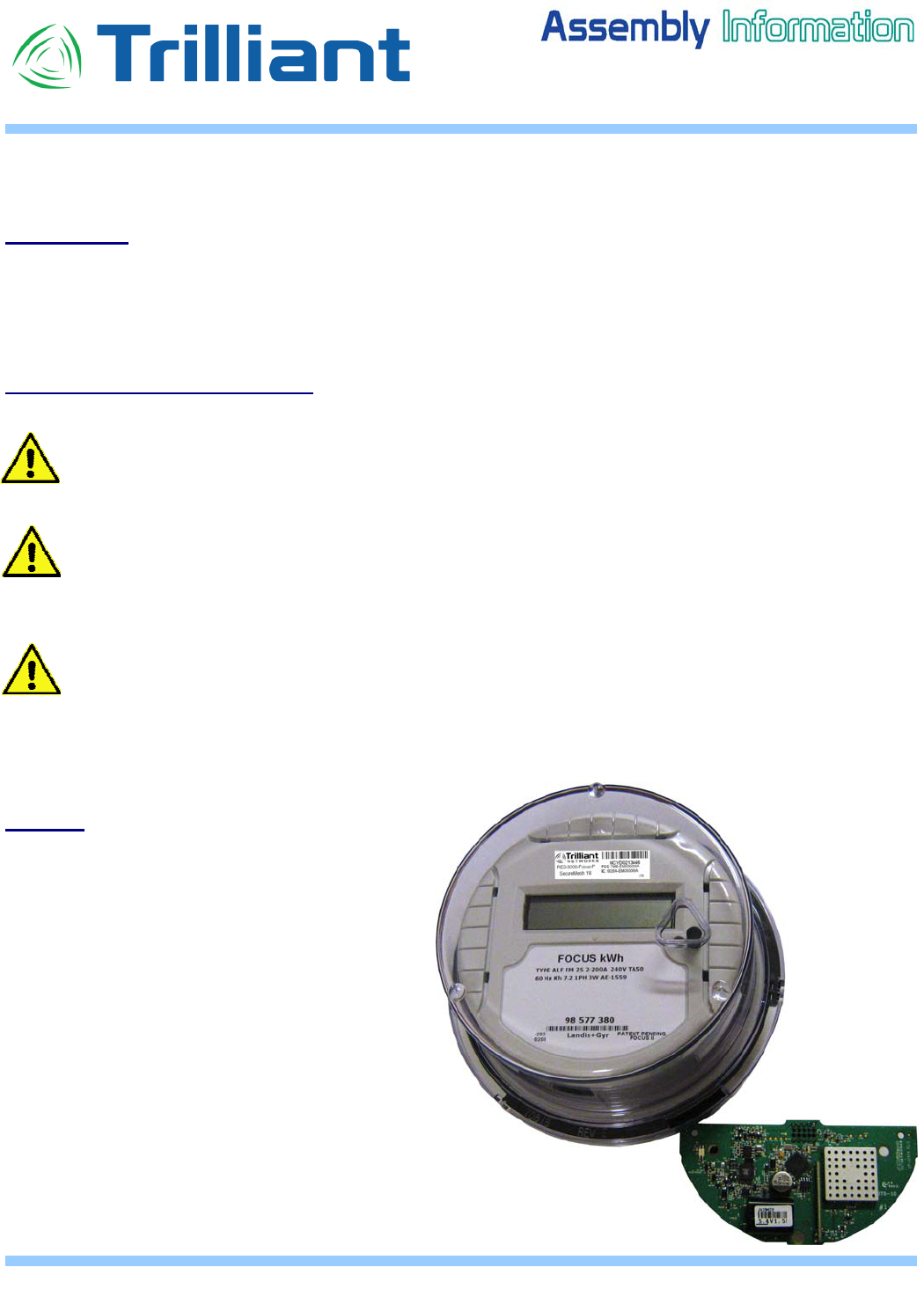
Introduction
This document will help the SecureMesh user to retrofit the product model RES-3000-
Focus/FocusAX in a Landis &Gyr Focus® meter as intended.
Safety and Assembly Cautions
- Warning: The meter carries lethal voltages. The meter must be completely
disconnected from any external circuits. Failure to observe this practice can result in
serious injury or death.
- Caution: These devices are electrostatic sensitive. It is best to use a grounded
electrostatic mat and wrist strap to prevent electrostatic discharge.
- Important: It is not necessary to completely separate the top of the meter from the base
of the meter for this retrofit procedure. However, if the two parts are completely
disconnected and separated, it is extremely important to keep each meter component
together for re-assembly. This is due to the top section of the meter containing
calibration “characterization” programming for the CTs in the meter base. If these
components get mixed up with other meter components, current measurement errors will
occur.
Material
• Focus meter (must be AMR configured)
• Trilliant SecureMesh RES-3000-
Focus/FocusAX .
• Mounting Screws - QTY=3 (provided by
L&G, ref.Trilliant # HS-0029B & HS-0029C)
• Self-Retaining Spacers-QTY=3
(provided by L&G, ref. Trilliant # HE-
0033C & HE-0033D)
• Serial # & FCC/IC label (provided by
L&G, ref Trilliant #.: HI-0307A)
SecureMesh retrofit for Focus/FocusAX meter
RES-3000-Focus
PA-0129A Rev. 1.0 June 18, 2010 Page 2 of 4
RES-3000-FocusAX
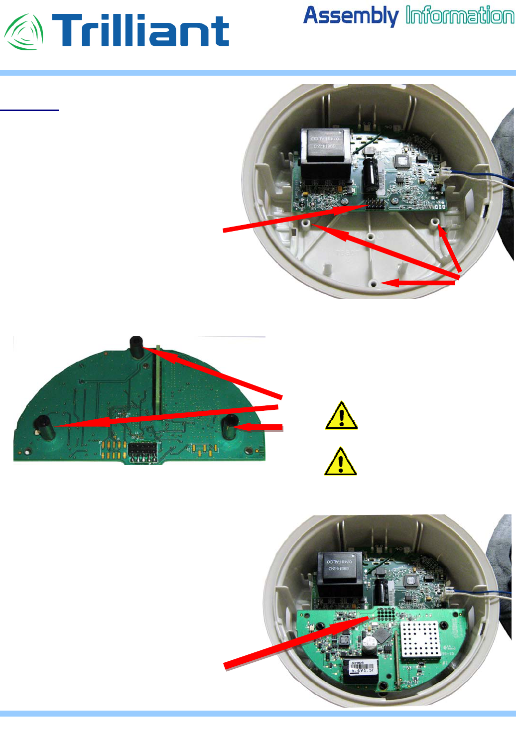
Procedure
1. If it is not already done, dis-assemble
the Focus meter clear cover and
unsnap the base from the top portion
of the case to access the 3 post
receptacle holes in the Top Portion
and the Focus/FocusAX board
connector as shown.
2. Snap the 3 plastic spacers into the
Trilliant SecureMesh RES-3000-
Focus/FocusAX PCB as showm.
3. Install the SecureMesh board by first
inserting the female connector in the
Focus/FocusAX male connector as
shown. The 3 spacers will be aligned with
the 3 holes in Focus/FocusAX meter Top
Portion.
Meter TOP
portion Post
receptacles
Plastic
spacers
Male-Female
connector mating
Female
connector
Male Interface
connector
HE-0033C
Short Spacer
HE-0033D
HE-0033D
Be careful to not damage
components and or PCB
traces when inserting spacers.
Do not apply excessive stress
on the PC board. Bending the
board too much would damage
components.
RES-3000-Focus
PA-0129A Rev. 1.0 June 18, 2010 Page 3 of 4
RES-3000-FocusAX
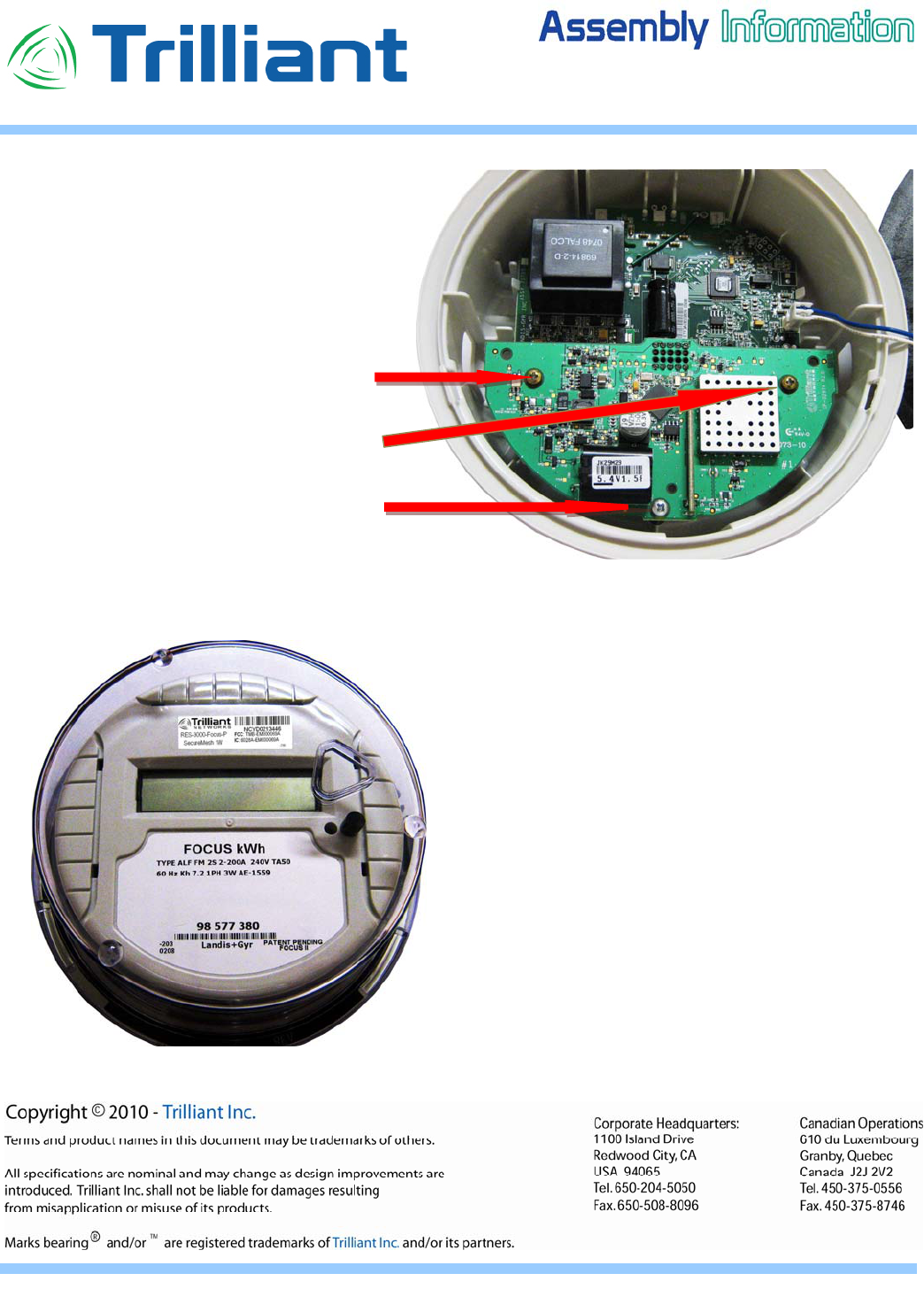
4. Attach the three (3) mounting screws
through the SecureMesh PCB into
the 3 plastic spacers so that the
SecureMesh board is held securely
in place.
5. Affix any missing label (Ref.: HI-0307A) on
the meter Top Portion,
finalize inspection & test as required
6. Reassemble the Focus Top portion by
snapping it into the bottom portion and affix
the clear cover on its base.
7. Perform functional test.
Screw
Ref: HS-0029B
Screw
Ref: HS-0029B
Screw
Ref: HS-0029C
RES-3000-Focus
PA-0129A Rev. 1.0 June 18, 2010 Page 4 of 4
RES-3000-FocusAX
SecureMesh Radio Specifications:
• IEEE Standard : IEEE 802.15.4
• Power Output : +30 dBm
• Radio Sensitivity : -99 dBm
• RF Data rate : 250 kbps
• Operating Frequency : 2.400-2.483 GHz
• Network Topology : Mesh
• Modulation : O-QPSK
• Physical Dimensions : 2.33” x 4.70”
• Antenna : Dipole, 3.5 dBi
Industry Canada and Federal Communication Commission Compliance Statement
This device complies with Part 15 of the FCC Rules. Operation is subject to the following two conditions:
1. This device may not cause harmful interference, and
2. This device must accept any interference received, including interference that may cause
undesired operation.
FCC Warning
Changes or modifications not expressly approved by the party responsible for compliance could void the
user’s authority to operate the equipment.
FCC Interference Statement
This equipment has been tested and found to comply with the limits for a Class B digital device, pursuant
to Part 15 of the FCC Rules. These limits are designed to provide reasonable protection against harmful
interference in a residential installation. This equipment generates uses and can radiate radio frequency
energy and, if not installed and used in accordance with the instructions, may cause harmful interference
to radio communications. However, there is no guarantee that interference will not occur in a particular
installation. If this equipment does cause harmful interference to radio or television reception, which can be
determined by turning the equipment off and on, the user is encouraged to try to correct the interference by
one of the following measures:
• Reorient or relocate the receiving antenna.
• Increase the separation between the equipment and receiver.
• Connect the equipment into an outlet on a circuit different from that to which the receiver is
connected.
• Consult the dealer or an experienced radio/TV technician for help.
To comply with FCC and Industry Canada RF exposure limits for general population / uncontrolled
exposure, the antenna(s) used for this transmitter must be installed to provide a separation
distance of at least 20 cm from all persons and must not be co-located or operating in conjunction
with any other antenna or transmitter.