Trilliant Networks SC2110 802.11 Based, Fixed Wireless Node User Manual installation Manual
Trilliant Networks, Inc. 802.11 Based, Fixed Wireless Node installation Manual
Contents
- 1. Users Manual
- 2. installation Manual
installation Manual
SkyConnector Indoor
Installation Guide
E
P
C
:
G
N
I
N
R
A
W
R
E
P
O
R
P
M
I
N
O
I
T
A
L
L
A
T
S
N
I
E
G
A
M
A
D
D
L
U
O
C
R
E
T
U
P
M
O
C
R
U
O
Y
R
E
W
O
PR
E
T
U
P
M
O
C
E
P
C
E
P
C
:
G
N
I
N
R
A
W
R
E
P
O
R
P
M
I
N
O
I
T
A
L
L
A
T
S
N
I
E
G
A
M
A
D
D
L
U
O
C
R
E
T
U
P
M
O
C
R
U
O
Y
R
E
W
O
PR
E
T
U
P
M
O
C
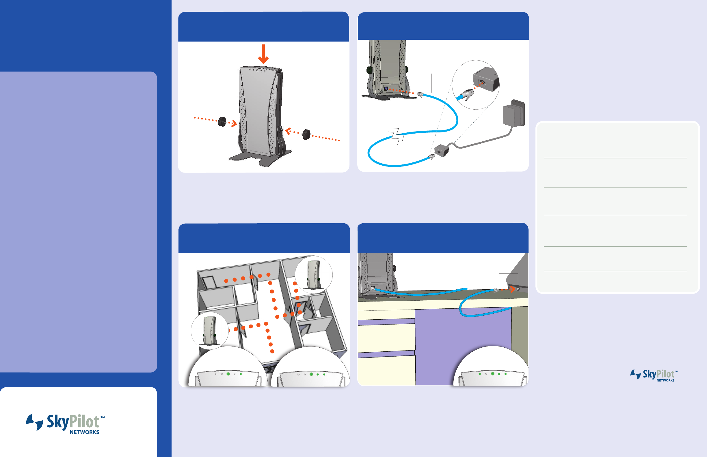
Power on
2
Plug one end of the 25-foot Ethernet cable into the RJ-45 port on the SkyConnector and
the other end into the port labeled “CPE” on the power injector.
Connect the AC adapter to the power injector, and plug the adapter into an AC outlet.
The Power LED lights to indicate the device is powered on.
RJ-45 port
Ethernet
cable
Move the SkyConnector to dierent parts of the building to nd the strongest SkyPilot
network signal. When the SkyConnector detects a signal, the WAN Act (WAN Activity)
LED starts to blink. (The faster the LED blinks, the stronger the signal.) If the WAN Act
LED does not start blinking within 30 seconds, try another location.
90 seconds after a signal is located, the WAN Link LED should start blinking, slowly then
more rapidly. When the WAN Link LED turn solid, you are connected to the network.
PWR
LAN WAN
LinkLink ActAct
Remove the adhesive backing from the four foot pads and place them on the underside
of the desk stand.
Place the SkyConnector in the desk stand and insert the two knobs as shown. Tighten
the knobs to secure the device.
Attach stand
2
1
Attach one end of the 7-foot Ethernet cable to the port labeled “Computer” on the power
injector and the other end into an Ethernet port on your personal computer or other
network device, such as a router.
When SkyConnector Indoor is properly connected to the computer, the LAN Link LED
lights to indicate a successful connection between the devices.
Connect computer
4
Your SkyPilot™ SkyConnector™
Indoor kit provides everything you
need to set up your SkyConnector
and connect to a provider’s wireless
mesh network.
Contents of the kit
• SkyConnector Indoor
• Desk stand and mounting knobs
• Power injector
• AC adapter
• Mounting hardware
• Two Ethernet cables (25-foot
and 7-foot)
About the SkyConnector
Your SkyConnector is a plug-and-
play device that connects you to a
SkyPilot wireless network providing
wireless access to the Internet.
For optimal operation, you need to
place the SkyConnector in a loca-
tion that has a line of sight to other
SkyPilot equipment.
2055 Laurelwood Road
Santa Clara, CA 95054-2747
(408) 764-8000 or
(866) SKYPILOT
www.skypilot.com
What‘s next?
Review the documentation provided to you
by your service provider for instructions on
conguring your computer for access to the
Internet as well as broadband applications
and services.
AC adapter
power injector
mounting knob
computer
desk stand
Locate signal
3
Blinking WAN Act LED indi-
cates network signal.
PWR
LAN WAN
LinkLink ActAct
Solid WAN Act LED indi-
cates network connection.
PWR
LAN WAN
Link Link Act Act
Solid LAN Link light indicates
successful connection with
computer.
RJ-45 port
Network information
ISP help desk
IP address
Netmask
DNS (name servers)
© 2006 SkyPilot Networks, Inc. All rights reserved. SkyConnector, SkyPilot,
SkyPilot Networks, the SkyPilot logo, and other designated trademarks, trade
names, logos, and brands are the property of SkyPilot Networks, Inc. or their
respective owners. Product specications are subject to change without notice.
This material is provided for informational purposes only; SkyPilot assumes
no liability related to its use and expressly disclaims any implied warranties of
merchantability or tness for any particular purpose.

FCC Regulatory Information
FCC Radio Frequency Interference Statement
This equipment has been tested and found to comply with the limits for a Class B
digital device, pursuant to Part 15 of the FCC Rules. These limits are designed to
provide reasonable protection against harmful interference in a residential
installation. This equipment generates, uses and can radiate radio frequency
energy and, if not installed and used in accordance with the instructions, may
cause harmful interference to radio communications. However, there is no
guarantee that interference will not occur in a particular installation. If this
equipment does cause harmful interference to radio or television reception,
which can be determined by turning the equipment off and on, the user is
encouraged to try to correct the interference by one or more of the following
measures:
o Reorient or relocate the receiving antenna.
o Increase the separation between the equipment and receiver.
o Connect the equipment into an o
which the receiver is connected.
utlet on a circuit different from that to
Consult the dealer or an experienced radio/TV technician for help.
pproval of the manufacturer void the user's authority to
perate the equipment.
o
The user of this product is cautioned that changes or modifications made to the
equipment without the a
o
FCC Radiation Exposure Limits
To comply with FCC RF exposure requirements in section 1.1307, a minimum
paration distance of 40 cm (16 inches) is required between the antenna and all
persons.