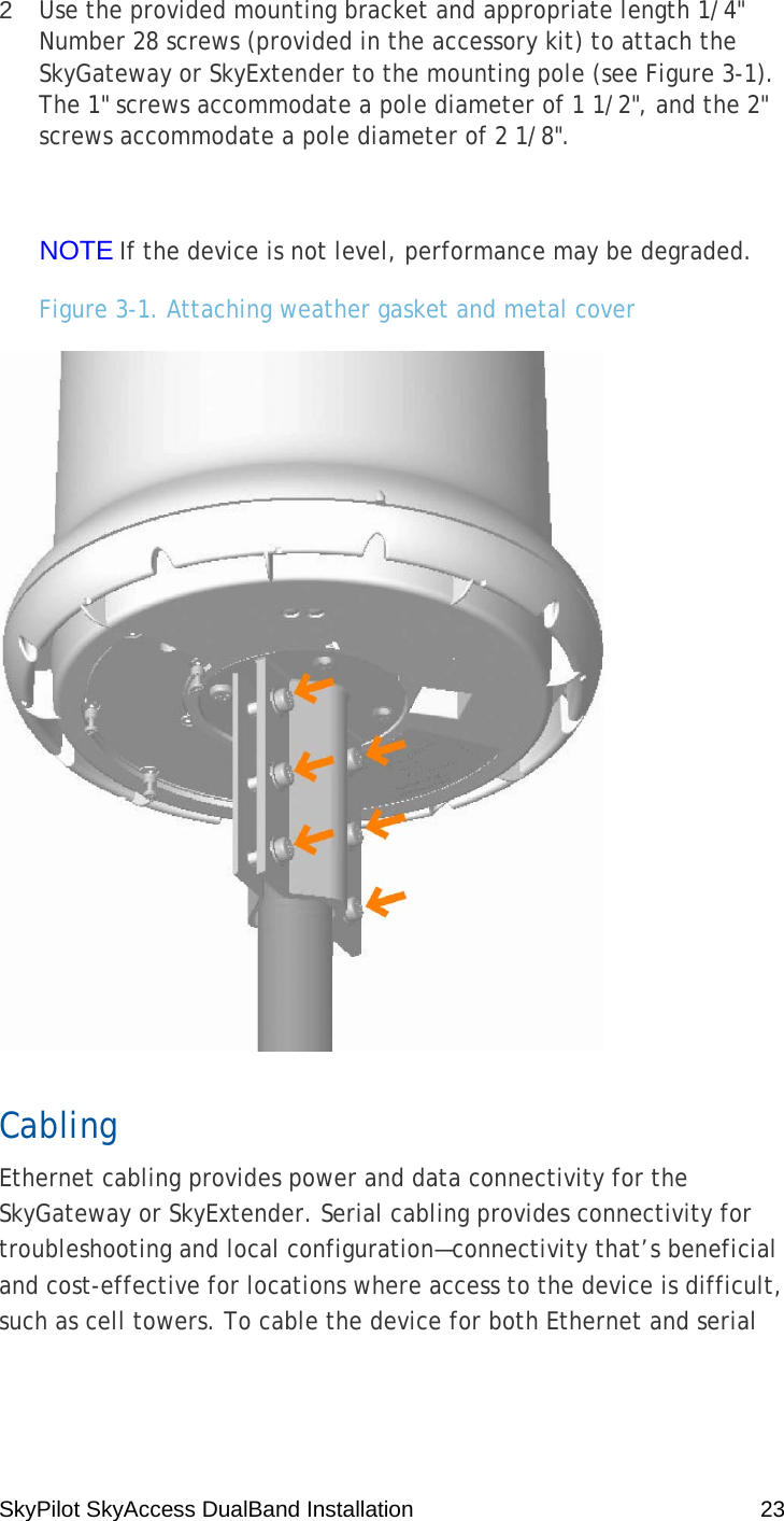
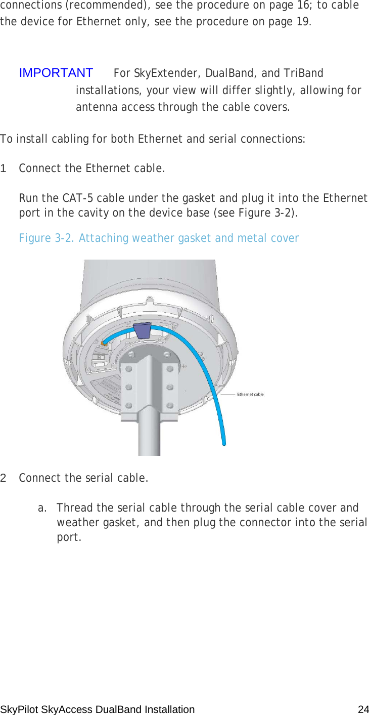
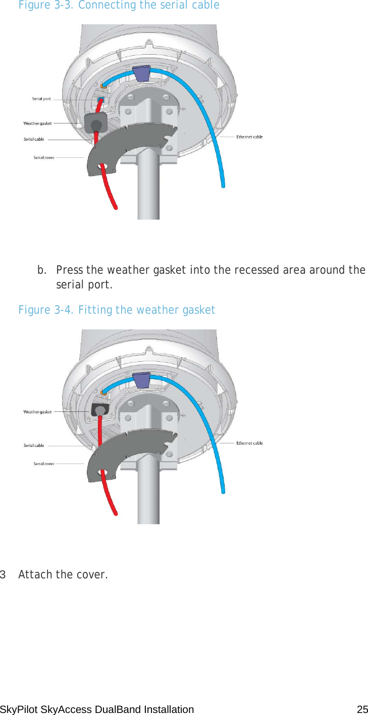
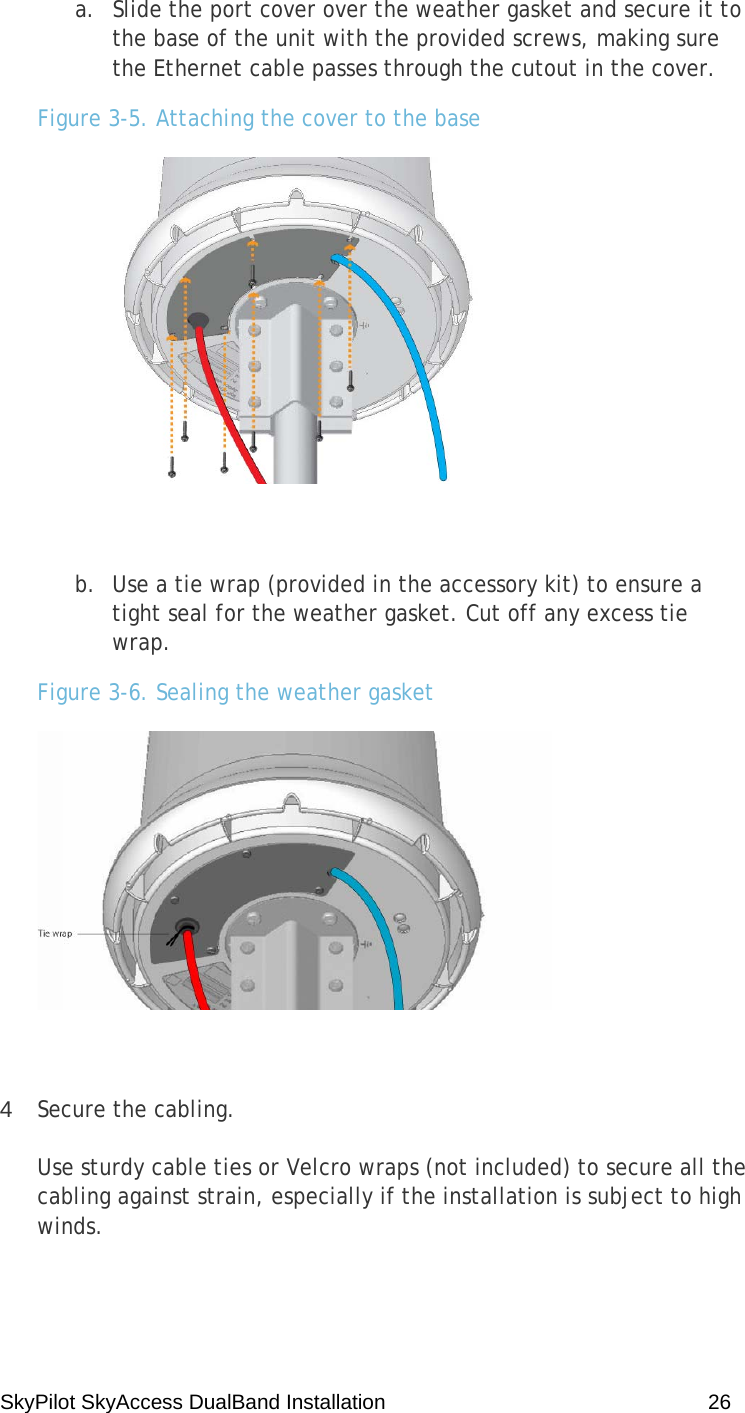
Trilliant Networks SD1087 SkyExtender and SkyGateway units User Manual Manual
Trilliant Networks, Inc. SkyExtender and SkyGateway units Manual
UserManual.wiki
>
Trilliant Networks
>
SD1087 User Manual
>
Manual
Contents
1.
Manual
2.
Spec
Manual
Navigation menu
Upload a User Manual
Namespaces
Wiki Guide
HTML
PDF
Info
Views
User Manual
Discussion / Help
Navigation

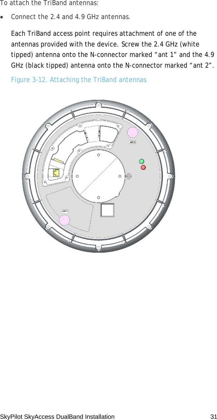
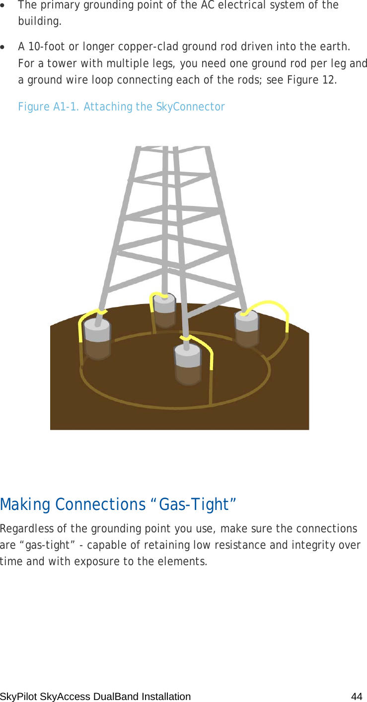
![SkyPilot SkyAccess DualBand Installation 7 Conventions Used in This Guide This section describes the text and syntax conventions used throughout this guide. Text Conventions This guide uses the following text conventions: • Italic is used to introduce new terms. • Bold is used to indicate what you click or type in a graphical user interface (for example, commands names or text being entered). In examples showing user interaction with the command-line interface, bold is used to indicate user input as opposed to command output. • A monospace font is used for code elements (variable names, data values, function names, and so forth), command lines, scripts, and source code listings. • Italic-monospace is used for replaceable elements and placeholders within code listings. Syntax Conventions This guide uses the following conventions when showing syntax: • Angle brackets, “<“ and “>”, enclose mandatory elements. You must enter these elements. For example: ping <IP-address> • Square brackets, “[“ and “]”, enclose optional elements. You can omit these elements. For example: show filter [filter-table-number] Square brackets are also used to show the current value of parameters in the output of some commands. • A vertical bar, “|”, separates choices. For example: show bridge [cache | port]](https://usermanual.wiki/Trilliant-Networks/SD1087.Manual/User-Guide-863475-Page-7.png)