Trilliant Networks SD1087 SkyExtender and SkyGateway units User Manual Manual
Trilliant Networks, Inc. SkyExtender and SkyGateway units Manual
Contents
- 1. Manual
- 2. Spec
Manual

SkyPilot
SkyGateway/SkyExtender
Installation
Contents
Contents 3
About This Guide 5
Audience and Purpose 6
How This Guide Is Organized 6
Conventions Used in This Guide 7
Introduction 9
Solution Overview 10
Mesh Network 10
SkyGateway 12
SkyExtender Devices 12
SkyConnector and SkyAccess DualBand 13
Your SkyGateway/SkyExtender Kit 15
Kit Contents 16
What Else You Need 17
Installing and Configuring the SkyGateway/SkyExtender 19
Planning your Installation 20
SkyGateway Installation 21
SkyExtender Installation 21
GPS and the SkyGateway/SkyExtender 21
Mounting 22
Cabling 23
Attaching Antennas 30
Powering Up 32
Making Power and Network Connections 32
Monitoring the Power-On Sequence 36
Configuring the SkyGateway/SkyExtender 40
Accessing the Command-Line Interface 41
Troubleshooting 41
Grounding Guidelines 43
General Grounding Strategy 43
Making Connections “Gas-Tight” 44
Checking Cold-Water Pipe Integrity 45
Measuring Resistance 45
Adding Surge Protection 45
Grounding Checklist 46
FCC Statements 47
FCC Class A Notice 47
FCC Class B Notice Error! Bookmark not defined.
The SkyPilot SkyAccess DualBand Installation and Setup Guide 4
Maximum Permissible Exposure 47
IC RSS-210 statements 48

About This Guide
This guide explains how to install and set up a SkyPilot™ SkyGateway™,
SkyExtender™, SkyExtender DualBand, or SkyExtender TriBand device to
provide wireless network access to users of a SkyPilot wireless mesh network.
It assumes administrator-level knowledge of IP networks and a familiarity with
configuring wireless devices.
Chapter Highlights
• Audience and purpose
• How this guide is organized
• Conventions used in this guide
SkyPilot SkyAccess DualBand Installation 6
Audience and Purpose
This guide provides directions for installing and setting up a SkyPilot
SkyGateway, SkyExtender, SkyExtender DualBand, or SkyExtender TriBand
device that can provide access to users of a SkyPilot wireless mesh network.
This guide assumes administrator-level knowledge of IP networks and a
familiarity with configuring wireless devices.
How This Guide Is Organized
This guide is organized as follows:
• Chapter 1, “Introduction,” provides an overview of the SkyPilot Networks
solution, describes the SkyPilot devices, and then illustrates how they
combine to form a mesh network.
• Chapter 2, “Your SkyGateway/SkyExtender Kit,” provides the information
you need before you begin your installation.
• Chapter 3, “Installing and Configuring the SkyGateway/SkyExtender,”
provides instructions for the physical installation of the SkyGateway or
SkyExtender as well as background information about configuration and
references to associated procedures.
• Appendix A, “Grounding Guidelines,” provides direction on protecting your
SkyPilot device with proper grounding and surge protection.
• Appendix B, “FCC Statements,” provides the FCC radio frequency
interference statements for the SkyGateway and SkyExtender devices..
• Appendix C, “Pinouts,” provides pinouts for connectors and adapters to
connect to the Ethernet interface port labeled “CPE” on the
SkyGateway/SkyExtender power injector and the device’s serial interface..
SkyPilot SkyAccess DualBand Installation 7
Conventions Used in This Guide
This section describes the text and syntax conventions used throughout this
guide.
Text Conventions
This guide uses the following text conventions:
• Italic is used to introduce new terms.
• Bold is used to indicate what you click or type in a graphical user interface
(for example, commands names or text being entered). In examples
showing user interaction with the command-line interface, bold is used to
indicate user input as opposed to command output.
• A monospace font is used for code elements (variable names, data values,
function names, and so forth), command lines, scripts, and source code
listings.
• Italic-monospace is used for replaceable elements and placeholders
within code listings.
Syntax Conventions
This guide uses the following conventions when showing syntax:
• Angle brackets, “<“ and “>”, enclose mandatory elements. You must enter
these elements. For example:
ping <IP-address>
• Square brackets, “[“ and “]”, enclose optional elements. You can omit
these elements. For example:
show filter [filter-table-number]
Square brackets are also used to show the current value of parameters in
the output of some commands.
• A vertical bar, “|”, separates choices. For example:
show bridge [cache | port]

SkyPilot SkyAccess DualBand Installation 9
Introduction
This chapter provides an overview of the SkyPilot Networks solution,
describes the SkyPilot devices, and then illustrates how they combine
to form a mesh network.
Chapter Highlights
• Solution overview
• Mesh network
• SkyGateway
• SkyExtender devices
• SkyConnector
1
SkyPilot SkyAccess DualBand Installation 10
Solution Overview
SkyPilot Networks delivers a wireless, end-to-end broadband solution
that seamlessly supports high-capacity, high-coverage mesh networks.
Designed for managed-access networks and service providers, the
SkyPilot network takes broadband wireless the “last mile” with a cost-
effective, robust infrastructure solution.
Based on a high-performance architecture that deploys intelligent
antenna arrays, the SkyPilot network delivers a dynamic broadband
solution with significant advantages for business and home users.
SkyPilot wireless devices are simple to install and easily fit into any
type of wireless environment—metropolitan, business, or home.
The auto-discovery and rapid provisioning features of a SkyPilot
wireless mesh network can greatly reduce deployment and maintenance
costs. Multiple topology options and network scalability create
intriguing options for rapidly expanding a metro Wi-Fi customer base.
SkyPilot devices’ multiple antenna configurations work within mixed-
use environments of municipal applications and broadband Internet
access, supporting public-private partnerships such as public safety
services.
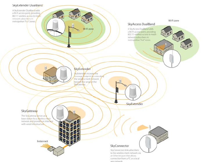
Mesh Network
The typical configuration for a SkyPilot network is a mesh topology,
which uses SkyExtenders to extend range and add network flexibility. In
a mesh configuration, subscribers can either connect directly to the
SkyGateway or connect indirectly via SkyExtenders (see Figure ). In
addition to adding range, a mesh network allows connections from
locations where obstructions prevent line-of-sight access to a
SkyGateway hub.
Mesh networks are ideal for dense subscriber environments, for filling
in coverage “holes,” and for reaching subscribers in areas where RF
communication is obstructed by hills, trees, buildings, or other
obstacles.
SkyPilot SkyAccess DualBand Installation 11
Figure 1. SkyPilot wireless mesh network
SkyPilot SkyAccess DualBand Installation 12
SkyGateway
The SkyGateway operates as a base station for a wireless mesh
network. It provides an interface between wired infrastructure and a
wireless network of subscribers who enjoy secure, high-speed access to
the Internet or to wide area networks.
A SkyPilot wireless network requires at least one SkyGateway for
operation. If necessary, you can add additional SkyGateways to increase
network capacity or provide redundancy.
The SkyGateway typically resides at a location with easy access to
wired infrastructure—usually a POP (point of presence) or data center.
For optimal performance, install the SkyGateway on an elevated site
such as a cell tower or the top of a tall building.
SkyExtender Devices
SkyExtenders, SkyExtender DualBands, and SkyExtender TriBands
provide a cost-effective way to add capacity and balance network loads
by operating as “repeaters” to extend the wireless range of a
SkyGateway (see Figure ). You can add any SkyExtender device to your
network to expand your coverage footprint and provide redundancy
through SkyPilot’s mesh networking features. SkyExtender devices
(except DualBands) can provide subscribers with a direct connection to
the wireless network via the device’s Ethernet port.
SkyExtender DualBand is a dual-radio solution that combines SkyPilot’s
long-range, high-capacity 5 GHz mesh backhaul with a high-powered
2.4 GHz 802.11b/g access point that allows service providers and
municipalities to offer standard Wi-Fi services over great distances—for
targeted hot zones or dense, ubiquitous coverage patterns.
SkyExtender TriBand integrates a 5.8 GHz mesh backhaul with the
DualBand’s access point and adds a third radio accessible through a
second access point. The second access point leverages the 4.9 GHz
Public Safety band, using 802.11a communication protocol. Each access
point uses a single antenna, and these
SkyPilot SkyAccess DualBand Installation 13
antennas have similar coverage patterns, providing a cost-effective
solution for municipal networks.
For optimal performance, install the SkyExtender in an elevated
location such as a roof, tower, or utility pole.
SkyConnector and SkyAccess DualBand
SkyConnectors link your subscribers to the SkyPilot wireless network. An
Ethernet port on the device allows a connection to a subscriber’s
computer, or to a local area network (LAN) via a data switch or router.
Designed for installation by the service provider, the SkyConnector
attaches to an external structure such as an eave, roof, or pole.
The SkyAccess DualBand offers the same features as a SkyConnector,
plus a Wi-Fi access point that enables service providers and
municipalities to provide standard 802.11 wireless access over great
distances, for targeted hot zones, or for dense coverage patterns.

SkyPilot SkyAccess DualBand Installation 15
Your SkyGateway/SkyExtender
Kit
Your SkyPilot SkyGateway/SkyExtender kit provides the basic
equipment you need to install the device and configure it for operation
on a SkyPilot wireless mesh network. This chapter describes that
equipment and lists additional items you should have on hand before
starting installation.
Chapter Highlights
• Kit contents
• What else you need
2
SkyPilot SkyAccess DualBand Installation 16
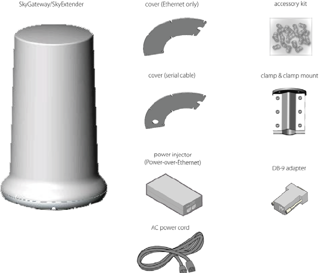
Kit Contents
Figure 2-1 shows the contents of the SkyGateway/SkyExtender
installation kit.
Figure 2-1. What the basic kit provides
Additionally, DualBand kits contain two 2.4 GHz (white tipped)
omnidirectional antennas.
And TriBand kits contain the following items in addition to the basic
SkyExtender kit:
• One 2.4 GHz (white tipped) antenna
• One 4.9 GHz (black tipped) antenna
SkyPilot separately offers accessories for different types of installation,
including a surge suppressor, a tilt mount kit, and an all-in-one mount
kit for light poles that includes a power supply and surge suppressor.

SkyPilot SkyAccess DualBand Installation 17
For more information, visit the SkyPilot website at
www.skypilot.com/support/.
What Else You Need
Before starting installation, you also need the following:
• For basic mounting:
o 7/16" wrench
o Phillips screwdriver
• For pole mounting:
o Magnetic level
o Steel pole between 1 1/8" (2.87 cm) and 1 3/8" (3.48 cm) in
diameter
• For network cabling:
o A spool of CAT5 network cable (shielded cable is
recommended)
o RJ-45 straight through cable for a serial connection to a
console (standard CAT-5 patch cable will work)
NOTE SkyPilot strongly recommends always running a serial
cable from SkyGateways and SkyExtenders to
facilitate troubleshooting.
NOTE Ethernet cabling must comply with NEC/CEC
requirements for outdoor CAT-5 cables. The cabling’s
outer jacket must be clearly marked as CAT-5e per
ANSI/TIA/EIA-568-B.2.
o Crossover cable (for connecting to a an access point, switch,
or router)
o RJ-45 connectors (connectors without a protective “boot”
are recommended)
SkyPilot SkyAccess DualBand Installation 18
o RJ-45 crimping tool
o External Surge protection device
• For configuration:
o Computer with a serial port, a terminal emulation program,
a network interface card, and a Web browser (laptop
recommended for convenience)

SkyPilot SkyAccess DualBand Installation 19
Installing and Configuring the
SkyGateway/SkyExtender
This chapter provides instructions for planning and performing the
physical installation of the SkyGateway or SkyExtender and then
configuring it.
Chapter Highlights
• Planning your installation
• GPS and the SkyGateway/SkyExtender
• Mounting
• Cabling
• Attaching antennas
• Powering up
• Configuring the SkyGateway/SkyExtender
• Accessing the command-line interface
• Troubleshooting
3
SkyPilot SkyAccess DualBand Installation 20
Planning your Installation
When choosing a site for the SkyGateway or SkyExtender, consider the
radio frequency (RF) environment and the physical layout of the area.
Trees, buildings, and hills can attenuate or block a wireless signal.
When assessing a site, examine the overall topology of the wireless
path for possible obstructions—both existing and planned—as well as
seasonal changes of foliage and tree growth. The RF environment is
dynamic, and can deteriorate over time as structures appear or are
relocated.
Plan to use test signals to determine the suitability of the link topology
for target applications. Interference on your desired frequency results
in overlapping signals, causing outages or intermittent drops in
throughput.
Once you’ve identified a potential site, use a topographic map or path
profile software to ensure that terrain or obstacles will not interfere
with the links.
Your site survey should include an RF scan to identify available
frequencies. You should also check your preferred frequency at all
locations. A frequency that’s clear at one location may be crowded at
another. Frequency planning is a critical factor in planning and
implementing a wireless network. (For device operating frequencies,
see Appendix C, “Specifications.”)
The site survey process should be ongoing. To verify that a site is
relatively free of interference, make site audits every six to twelve
months, scheduling regular maintenance visits to coincide with the site
audits.
For TriBand installations, operators should review laws and regulations
regarding the registration and use of the 4.9 GHz frequency in the area
of deployment. For example, 4.9 GHz is used in the US for public safety
information.
SkyPilot SkyAccess DualBand Installation 21
NOTE Plan to configure the SkyGateway or SkyExtender
before mounting it. Some steps, such as those
requiring serial console access, are easier if the
device is more accessible. For information about
configuration, see “Configuring the
SkyGateway/SkyExtender” on page 30.
SkyGateway Installation
In a typical wide area wireless mesh network, you’ll install a
SkyGateway on a tower or the roof of a tall building. The direct
coverage area of the SkyGateway is usually proportional to the height
of the installation.
You can also set up a SkyGateway for use in smaller-scale networks—for
example, a high-capacity business, an academic campus
interconnection, or a local access network. For smaller networks, you
can install the SkyGateway on the roof of a medium-height building or
on a utility pole.
SkyExtender Installation
You can install a SkyExtender in any location where a strong signal from
a SkyGateway (or another SkyExtender) is available: home rooftops, tall
buildings, or light and utility poles. Having fewer obstructions means
greater signal strength, a higher signal-to-noise ratio, and more
throughput.
GPS and the SkyGateway/SkyExtender
The SkyGateway or SkyExtender uses a GPS (Global Positioning System)
signal to synchronize itself with other devices on the network. The
strongest GPS signal is available outdoors, where the device has an
unobstructed view of the sky. (For indoor installations, such as for
configuration and testing, the optimal location is on a windowsill or
other opening with access to the sky.)
SkyPilot SkyAccess DualBand Installation 22
Upon startup, a SkyGateway or SkyExtender searches for a GPS signal,
and if the device can’t detect a signal, it will be unable to complete
startup and won’t establish wireless connections with other devices.
You can configure a SkyGateway or SkyExtender even if the device
can’t detect a GPS signal. While the device is searching for the GPS
signal, press the TILDE key (~) to bypass the search; the device will
then proceed through the startup sequence.
NOTE The GPS search should be bypassed only for device
configuration, not for standard operation. Without a GPS
signal, data will not be reliably transmitted between
devices.
The LEDs on the base of the device will confirm availability of a GPS
signal. For more information on the LEDs and GPS signal acquisition, see
“Monitoring the Power-On Sequence” on page 27.
Mounting
The first step of physically installing the SkyGateway or SkyExtender is
to mount the device as described below.
NOTE The figures in this section show the SkyGateway. For
SkyExtender, DualBand, and TriBand installations, your view
will differ slightly, allowing for antenna access through the
cable covers.
To mount the SkyGateway/SkyExtender:
1 Attach a magnetic level to the 1.25” to 2.0” diameter steel
mounting pole to verify that the pole is plumb (straight).
IMPORTANT The figures in this section show the SkyGateway.
For SkyExtender, DualBand, and TriBand installations,
your view will differ slightly, allowing for antenna access
through the cable covers.
SkyPilot SkyAccess DualBand Installation 23
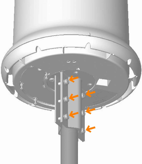
2 Use the provided mounting bracket and appropriate length 1/4"
Number 28 screws (provided in the accessory kit) to attach the
SkyGateway or SkyExtender to the mounting pole (see Figure 3-1).
The 1" screws accommodate a pole diameter of 1 1/2", and the 2"
screws accommodate a pole diameter of 2 1/8".
NOTE If the device is not level, performance may be degraded.
Figure 3-1. Attaching weather gasket and metal cover
Cabling
Ethernet cabling provides power and data connectivity for the
SkyGateway or SkyExtender. Serial cabling provides connectivity for
troubleshooting and local configuration—connectivity that’s beneficial
and cost-effective for locations where access to the device is difficult,
such as cell towers. To cable the device for both Ethernet and serial

SkyPilot SkyAccess DualBand Installation 24
connections (recommended), see the procedure on page 16; to cable
the device for Ethernet only, see the procedure on page 19.
IMPORTANT For SkyExtender, DualBand, and TriBand
installations, your view will differ slightly, allowing for
antenna access through the cable covers.
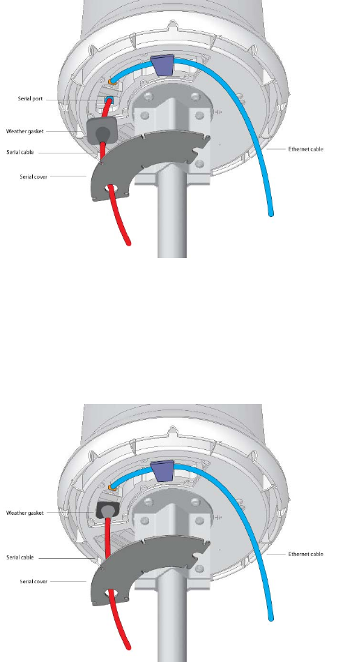
To install cabling for both Ethernet and serial connections:
1 Connect the Ethernet cable.
Run the CAT-5 cable under the gasket and plug it into the Ethernet
port in the cavity on the device base (see Figure 3-2).
Figure 3-2. Attaching weather gasket and metal cover
2 Connect the serial cable.
a. Thread the serial cable through the serial cable cover and
weather gasket, and then plug the connector into the serial
port.
SkyPilot SkyAccess DualBand Installation 25
Figure 3-3. Connecting the serial cable
b. Press the weather gasket into the recessed area around the
serial port.
Figure 3-4. Fitting the weather gasket
3 Attach the cover.
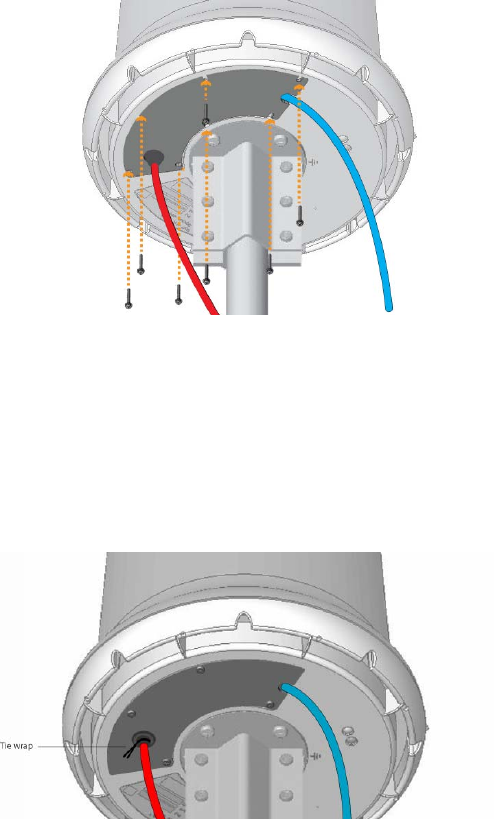
SkyPilot SkyAccess DualBand Installation 26
a. Slide the port cover over the weather gasket and secure it to
the base of the unit with the provided screws, making sure
the Ethernet cable passes through the cutout in the cover.
Figure 3-5. Attaching the cover to the base
b. Use a tie wrap (provided in the accessory kit) to ensure a
tight seal for the weather gasket. Cut off any excess tie
wrap.
Figure 3-6. Sealing the weather gasket
4 Secure the cabling.
Use sturdy cable ties or Velcro wraps (not included) to secure all the
cabling against strain, especially if the installation is subject to high
winds.
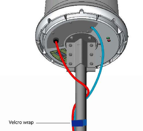
SkyPilot SkyAccess DualBand Installation 27
Figure 3-7. Secured cabling
SkyPilot SkyAccess DualBand Installation 28
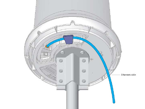
To install cabling for both Ethernet and serial connections:
1 Connect the Ethernet cable.
Run the CAT-5 cable under the gasket and plug it into the Ethernet
port in the cavity on the device base (see Figure 3-2).
Figure 3-8. Attaching weather gasket and metal cover
2 Attach the cover.
a. Slide the port cover over the weather gasket and secure it to
the base of the unit with the provided screws, making sure
the Ethernet cable passes through the cutout in the cover.
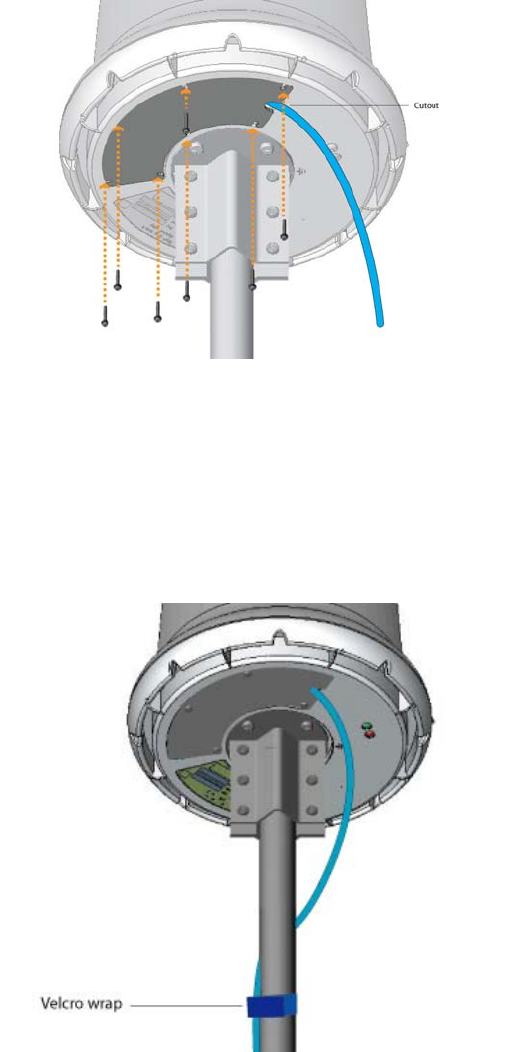
SkyPilot SkyAccess DualBand Installation 29
Figure 3-9. Attaching the cover to the base
3 Secure the cabling.
Use sturdy cable ties or Velcro wraps (not included) to secure all the
cabling against strain, especially if the installation is subject to high
winds.
Figure 3-10. Secured cabling
SkyPilot SkyAccess DualBand Installation 30
Attaching Antennas
Unless you’re installing a DualBand or TriBand, you can skip this
section. To attach the DualBand antennas, see the procedure on page
21; to attach the TriBand antennas, see the procedure on page 22.
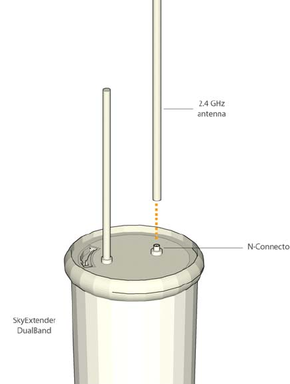
To attach the DualBand antennas:
• Connect the 2.4 GHz antennas.
IMPORTANT If you are attaching antenna other than those
provided by SkyPIlot, make sure you use the same type of
antenna to comply with FCC requirements and that the
antenna gain is equal to, or less than the gain of the
SkyPilot antenna.
Screw the antennas onto the standard N-connectors on the bottom
of the DualBand.
Figure 3-11. Attaching the DualBand antennas
SkyPilot SkyAccess DualBand Installation 31
To attach the TriBand antennas:
• Connect the 2.4 and 4.9 GHz antennas.
Each TriBand access point requires attachment of one of the
antennas provided with the device. Screw the 2.4 GHz (white
tipped) antenna onto the N-connector marked “ant 1” and the 4.9
GHz (black tipped) antenna onto the N-connector marked “ant 2”.
Figure 3-12. Attaching the TriBand antennas
SkyPilot SkyAccess DualBand Installation 32
Powering Up
To supply power to the SkyGateway or SkyExtender, perform the
procedures described in this section.
Making Power and Network Connections
To supply power to the SkyGateway or SkyExtender, perform the
procedures described in this section.
To make connections:
1 Attach the power supply for the SkyGateway or SkyExtender.
a. Connect the AC power cord to the AC adapter, and plug it
into an AC outlet.
b. Connect the Ethernet cable to the port labeled “CPE” on the
power injector.
IMPORTANT Be careful not to plug the Ethernet cable
connected to the SkyGateway or SkyExtender into the
port labeled “Computer.”
c. Plug the AC adapter into the power injector.
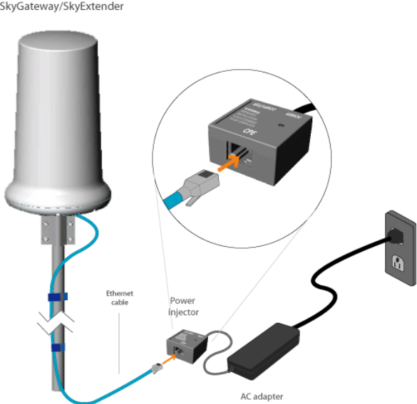
SkyPilot SkyAccess DualBand Installation 33
Figure 3-13. Providing power to the SkyGateway/SkyExtender
2 If you’re connecting a DualBand, skip this step. Likewise, if you’re
connecting a SkyExtender that will operate solely as a repeater on
the wireless mesh network, skip this step as a data connection is not
required.
Otherwise, connect the device to a WAN (for a SkyGateway) or a
PC/LAN (for a SkyExtender that’s also providing local access to the
wireless network).
NOTE DualBands don’t contain an Ethernet interface and can’t
detect any device connected to the power injector port
labeled “Computer”.
For a SkyGateway, connect a second Ethernet cable from the power
injector port labeled “Computer” to a router or data switch that
connects to the WAN or Internet (see Figure 3-14).
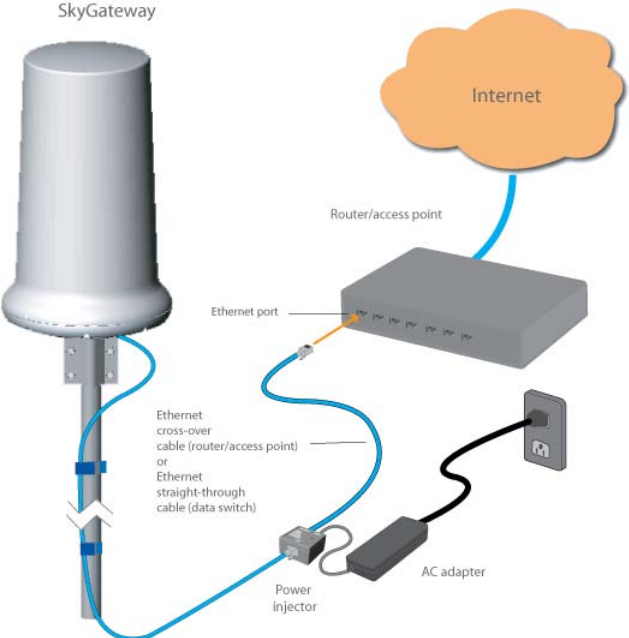
SkyPilot SkyAccess DualBand Installation 34
Figure 3-14. Connecting a SkyGateway to a router or data switch
For a SkyExtender (or TriBand, but not DualBand) that also gives
subscribers access to the wireless mesh network, connect a second
Ethernet cable from the power injector port labeled “Computer” to
a personal computer (see Figure 3-15) or to a router or data switch
providing a connection to a LAN (see Figure 3-16).
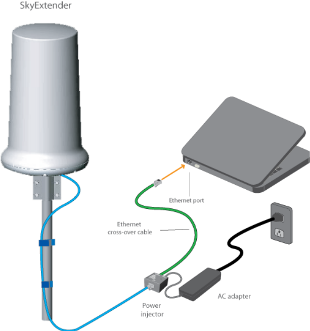
SkyPilot SkyAccess DualBand Installation 35
Figure 3-15. Connecting a SkyExtender/TriBand to a computer
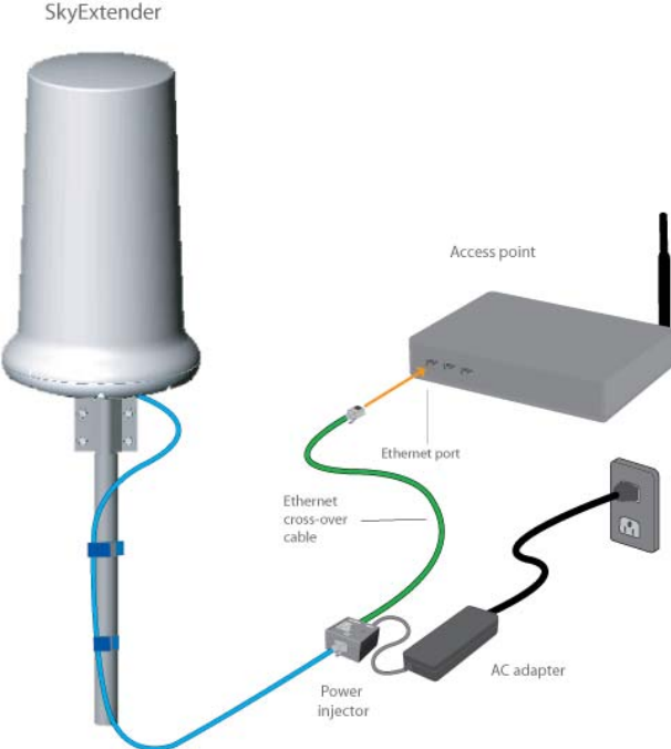
SkyPilot SkyAccess DualBand Installation 36
Figure 3-15. Connecting a SkyExtender/TriBand to a computer
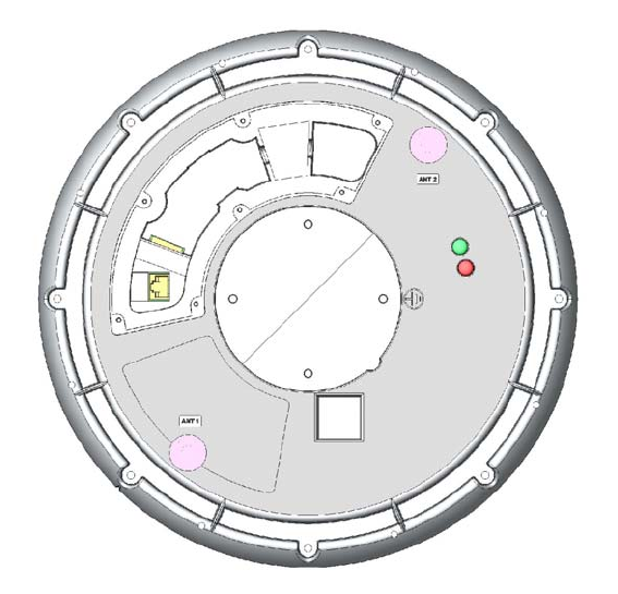
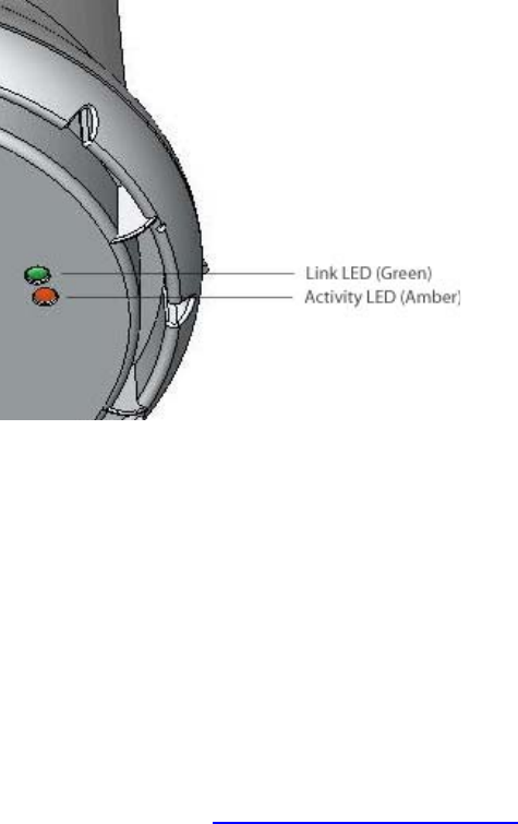
Monitoring the Power-On Sequence
When power is supplied to the SkyGateway or SkyExtender, it starts a
routine power-on sequence which you can monitor by observing the pair
of LED lights on the underside of the device.
The power-on sequence takes up to 15 minutes, depending on how
quickly the device can acquire a GPS signal.
NOTE The SkyGateway or SkyExtender must have access to a GPS
signal to complete its power-on sequence and start making wireless
network connections. And depending on your SkyPilot network
SkyPilot SkyAccess DualBand Installation 37
configuration, the device may be unable to connect to the network
until the device has been fully configured as described in “Configuring
the SkyGateway/SkyExtender” on page 30.
Figure 3-17. LED lights on the SkyGateway/SkyExtender base
The tables that follow provide detailed descriptions of device states
indicated by the LED lights. When both LED lights are lit and steady,
the SkyGateway or SkyExtender is successfully connected to the
wireless network.
You can observe the startup progress by attaching a laptop to the
device’s serial port, starting a terminal emulation program, and
rebooting the device. For more information about accessing a
SkyGateway or SkyExtender via a serial connection, refer to the
SkyPilot Command-Line Interface Reference, available from the
SkyPilot website at www.skypilot.com/support/.

SkyPilot SkyAccess DualBand Installation 38
Table 3-1. SkyGateway LED Status Lights
Device State Link LED (green) Activity LED (amber)
Startup in progress Slow staggered blinking
of both LEDs
Startup failure Off On
Initializing image (and
acquiring GPS signal) Blinks 4 times; repeats
cycle Blinks 4 times; repeats
cycle
Initialization failure Fast, synchronized
blinking of both LEDs
Successful
initialization, but
authorization failure
On Off
Connected On On

SkyPilot SkyAccess DualBand Installation 39
Table 3-2. SkyExtender/DualBand/TriBand LED Status Lights
Device State Link LED (green) Activity LED (amber)
Startup in progress Slow staggered blinking
of both LEDs
Startup failure Off On
Initializing image (and
acquiring GPS signal) Blinks 4 times; repeats
cycle Blinks 4 times; repeats
cycle
Initialization failure Fast, synchronized
blinking of both LEDs
Successful
initialization, but
authorization failure
On Off
Successful
initialization; heard
hello on RSSI
Off Blink (RSSI rate-based)
Successful
initialization; link is
not optimized, or is in
pre-authorization
Slow blink Blink (RSSI rate-based)
Successful
initialization; link is in
standby state on RSSI
Fast blink Blink (RSSI rate-based)
Connected On On

SkyPilot SkyAccess DualBand Installation 40
Configuring the SkyGateway/SkyExtender
To operate on the wireless mesh network, the SkyGateway or
SkyExtender requires a network configuration.
A SkyGateway will not transmit a wireless signal until it is configured,
and it will not be able to connect to other network devices without a
configuration.
SkyPilot offers two modes for provisioning devices with a configuration:
• Automatic - Requires the use of SkyPilot EMS software to create
configurations that an unattended central server can distribute to
devices on the wireless mesh network. Although automatic
provisioning requires more setup time than manual provisioning, it
greatly simplifies the administration of a growing network.
Detailed procedures for using EMS software are provided in SkyPilot
Network Administration , available from the SkyPilot website at
www.skypilot.com/support/.
• Manual - Usually performed in the field, manual provisioning
permits the configuration of a single device at a time, creating the
minimum settings required for a wireless link and storing them in
the device’s flash (nonvolatile) memory. Manual provisioning is a
logical choice if you’re installing a test network or rolling out a
small-scale installation that isn’t expected to expand.
For more information about provisioning modes and procedures, refer
to Getting Started with the SkyPilot Network and SkyPilot Network
Administration, available from the SkyPilot website at
www.skypilot.com/support/.
4
SkyPilot SkyAccess DualBand Installation 41
Accessing the Command-Line Interface
SkyPilot devices include a command-line interface which you can use
for manual provisioning and troubleshooting.
You can connect to a device and access its command-line interface
through Telnet over an Ethernet connection or via a terminal session
from a console connected to the device’s RJ-45 serial port. After
logging in (by supplying a password), you can enter commands at the
command prompt.
For detailed cabling and access instructions for the command-line
interface, refer to the SkyPilot Command-Line Interface Reference.
Troubleshooting
After making an Ethernet or serial connection to the SkyConnector, you
can manage and troubleshoot the device using a wide range of
commands available through the command-line interface.
For detailed troubleshooting procedures, refer to the “Troubleshooting”
section in SkyPilot Network Administration. There you’ll find
troubleshooting procedures for:
• Power-on problems
• Ethernet connectivity problems
• IP connectivity problems
• SkyGateway transmission problems
• Link failure problems

SkyPilot SkyAccess DualBand Installation 43
Grounding Guidelines
This appendix provides some guidelines for properly grounding the
SkyPilot Connector.
Proper grounding protects both your SkyPilot device and equipment
connected to it. For the surge protection circuitry built into the
SkyPilot equipment to be effective, proper grounding of the unit is
necessary. This is especially true if you’re installing devices on tall
structures, or in areas subject to lightning.
NOTE The techniques described in this appendix are intended as
general guidelines only and do not constitute a comprehensive
guide covering all installation scenarios. For maximum
protection, contact a qualified installation specialist who is
familiar with your operating environments. If lightning is a
threat in your area, consider a consultation with a lightning and
transient protection specialist.
General Grounding Strategy
To ensure optimal reliability, properly ground the metal base of the
SkyPilot device. The most efficient way to ground the device is to use
an 8 GA or larger wire to connect it to a ground point on the structure
or tower.
The three most common ground points are:
• A cold-water pipe. Make sure it is well connected to earth.
A
SkyPilot SkyAccess DualBand Installation 44
• The primary grounding point of the AC electrical system of the
building.
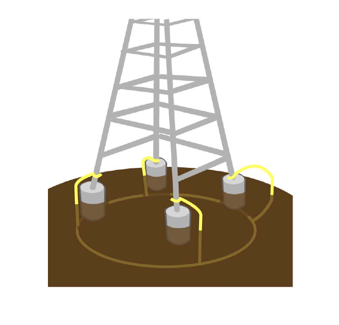
• A 10-foot or longer copper-clad ground rod driven into the earth.
For a tower with multiple legs, you need one ground rod per leg and
a ground wire loop connecting each of the rods; see Figure 12.
Figure A1-1. Attaching the SkyConnector
Making Connections “Gas-Tight”
Regardless of the grounding point you use, make sure the connections
are “gas-tight” - capable of retaining low resistance and integrity over
time and with exposure to the elements.

SkyPilot SkyAccess DualBand Installation 45
Use of an antioxide compound and proper sealing is essential. For
protection against corrosion, wrap all connections with Scotch® 130C
tape.
Checking Cold-Water Pipe Integrity
If you’re using a cold-water pipe for grounding, verify the integrity of
the ground. In some cases, sections of metal cold-water pipes may have
been repaired or extended with PVC material. PVC material or a
dielectric union will render a cold-water pipe ground unacceptable for
grounding.
Measuring Resistance
Verify that there is no more than 5 ohms of resistance between any two
ground points in the entire system. Also make sure that all ground
points on a structure are tied together. For example, if you use a
ground rod and a cold-water pipe as grounding points at different
locations on the same structure, you must tie them together.
Adding Surge Protection
If you’re installing a SkyPilot device in an area that’s subject to
lightning storms, SkyPilot recommends installing a surge protection
device (SPD) at both ends of the Ethernet cable - one at the SkyPilot
device and one at the point of entry to a building or enclosure.
SkyPilot offers SPDs with bracket and cabling designed for use with
SkyPilot equipment. For more information, visit SkyPilot customer
support at www.skypilot.com/support/ to view accessory guides for
SkyPilot-branded surge protection solution. (You may also purchase
SPDs from third-party vendors.)
SkyPilot SkyAccess DualBand Installation 46
Grounding Checklist
When grounding a SkyPilot device, use the following checklist to
confirm that your installation is adequately protected from power
surges and lightning.
• Connect a ground wire from the SkyPilot device to a ground system
on the building or tower.
• Use shielded CAT5 cabling and connect the drain wire of the shield
to ground at the SkyPilot device. (Leave the other end of the drain
wire unconnected.)
• Use the proper size down lead to connect a SkyPilot device on a
roof or tower to the ground system of indoor equipment.
• Verify that all points of the ground system are tied together with
less than 5 ohms resistance between any two points.
• Run the CAT5 cable inside the tower structure, tying the cable to
the tower leg at every 4 feet of length. For increased protection,
run the CAT5 cable through metallic conduit installed on the tower.
• Bleed off any static charge by installing a streamer-delaying, static-
dissipation array above the SkyPilot device.
• Install all lightning and surge protection devices in accordance with
UL 96A installation requirements for lightning protection systems
and the NFPA 780 standard for lightning protection.

SkyPilot SkyAccess DualBand Installation 47
FCC Statements
FCC Class A Notice
NOTE: This equipment has been tested and found to comply with the
limits for a Class A digital device, pursuant to part 15 of the FCC Rules.
These limits are designed to pro-vide reasonable protection against
harmful interference when the equipment is operated in a commercial
environment. This equipment generates, uses, and can radiate radio
frequency energy and, if not installed and used in accordance with the
instruction manual, may cause harmful interference to radio
communications. Operation of this equipment in a residential area is
likely to cause harmful interference in which case the user will be
required to correct the interference at his own expense.
Maximum Permissible Exposure
In order to meet Industry Canada, FCC and other regulatory
requirements for RF Exposure, the SkyGateway and SkyExtender units
must be located a minimum of 68.4 cm (26.9 inches) from all persons.
FCC 15.203 statement
Because DualBands and TriBands use standard RF connectors for the
external removable antennas, professional installation is required..
B
SkyPilot SkyAccess DualBand Installation 48
Regulatory Statements for Canada
IC RSS-210 statements
This Class A digital apparatus complies with Canadian ICES-003. Cet
appareil numerique de la classe A est conforme à la norme NMB-003
duCanada.
SkyPilot Networks SkyGateway devices are certified to meet the
requirements of RSS-210 for 5 GHz. Use of this device in a system must
follow the Canadian regulations. For further information, contact your
local Industry Canada office.
To reduce potential radio interference with other users, choose an
antenna type and and gain that ensures that equivalent isotropically
radiated power (EIRP) is no more than what is permitted for successful
communication.
This device is designed for operation with internal antennas having a
maximum gain of 18 dBi. Antennas displaying a gain greater than 18 dBi
are strictly prohibited for use with the SkyPilot device. (Required
antenna impedance is 50 ohms.)
NOTE High power radars are allocated as primary users (meaning they
have priority) of the 5650 5850 MHz band, and, these radars
could cause interference and/or damage to LE-LAN devices.
The SkyExtender is equipped with a pair of detachable antenna for the
optional Dual Band and Tri Band modes.
In addition to the provided antennas, SkyPilot SkyExtender DualBand
devices can also operate with the external antenna models for the 2.4
GHz band listed in Table B-1, or the same type of antenna with a
maximum gain of 7.4 dBi. Antennas not included in this list or having a
gain greater than 7.4 dBi are strictly prohibited for use with this
device. (Required antenna impedance is 50 ohms.)

SkyPilot SkyAccess DualBand Installation 49
I!! Caution !!!
Changes or modifications not expressly approved by the party
responsible for compliance could void the user’s authority to operate
the equipment
Table B-1. Antennas approved for use SkyExtender DualBand:
Manufacturer Model
Comet SF245
Comet SF245+12
Comet SF245+12x
A SkyPilot SkyExtender TriBand uses the 4.9 GHz band.
Prior to operating these devices, users are legally required to obtain
frequency licenses from their local communications governing agency.
Operating parameters are defined by the certification requirements of
the device and the limitations listed on the user license. Any of these
guidelines may affect the installation and operation of this device.”
SkyPilot SkyAccess DualBand Installation 50