Trimble Navigation ADLP Advanced Data Link, Padre (ADLP) User Manual ADL Vantage ADL Vantage Pro Guide indd
Trimble Navigation Ltd Advanced Data Link, Padre (ADLP) ADL Vantage ADL Vantage Pro Guide indd
UserManual.wiki
>
Trimble Navigation
>
ADLP User Manual
Users Manual
Navigation menu
Upload a User Manual
Namespaces
Wiki Guide
HTML
PDF
Info
Views
User Manual
Discussion / Help
Navigation


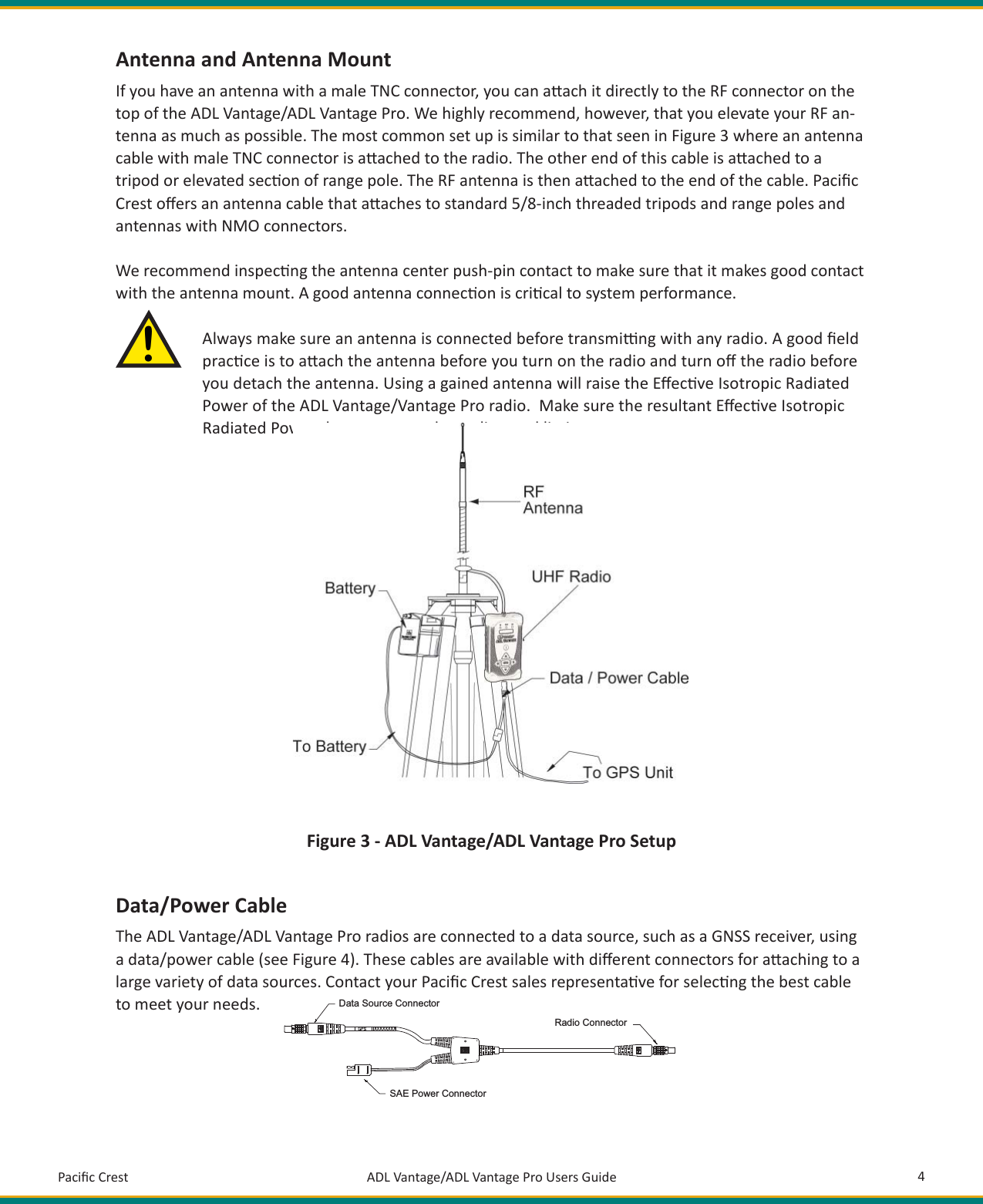
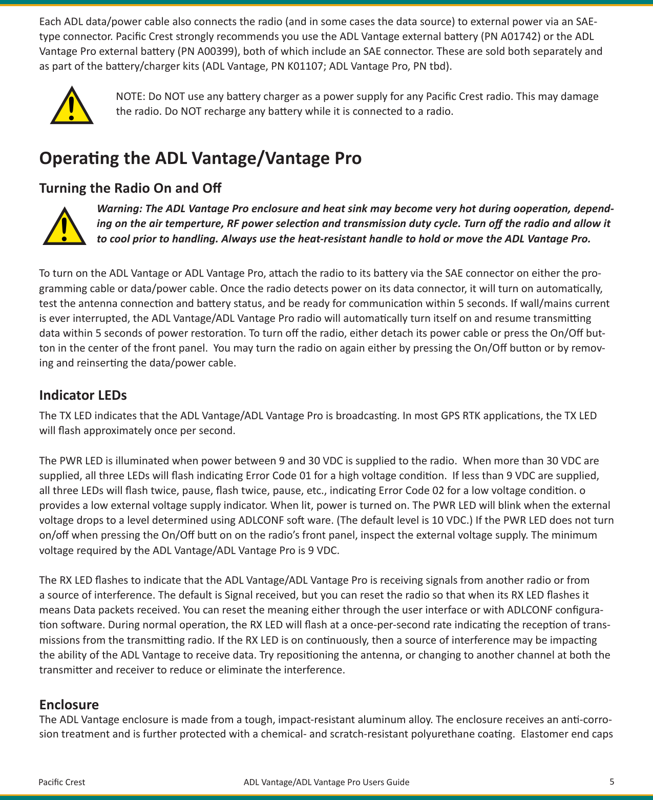
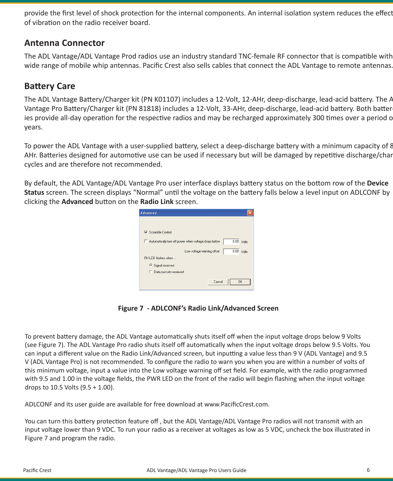
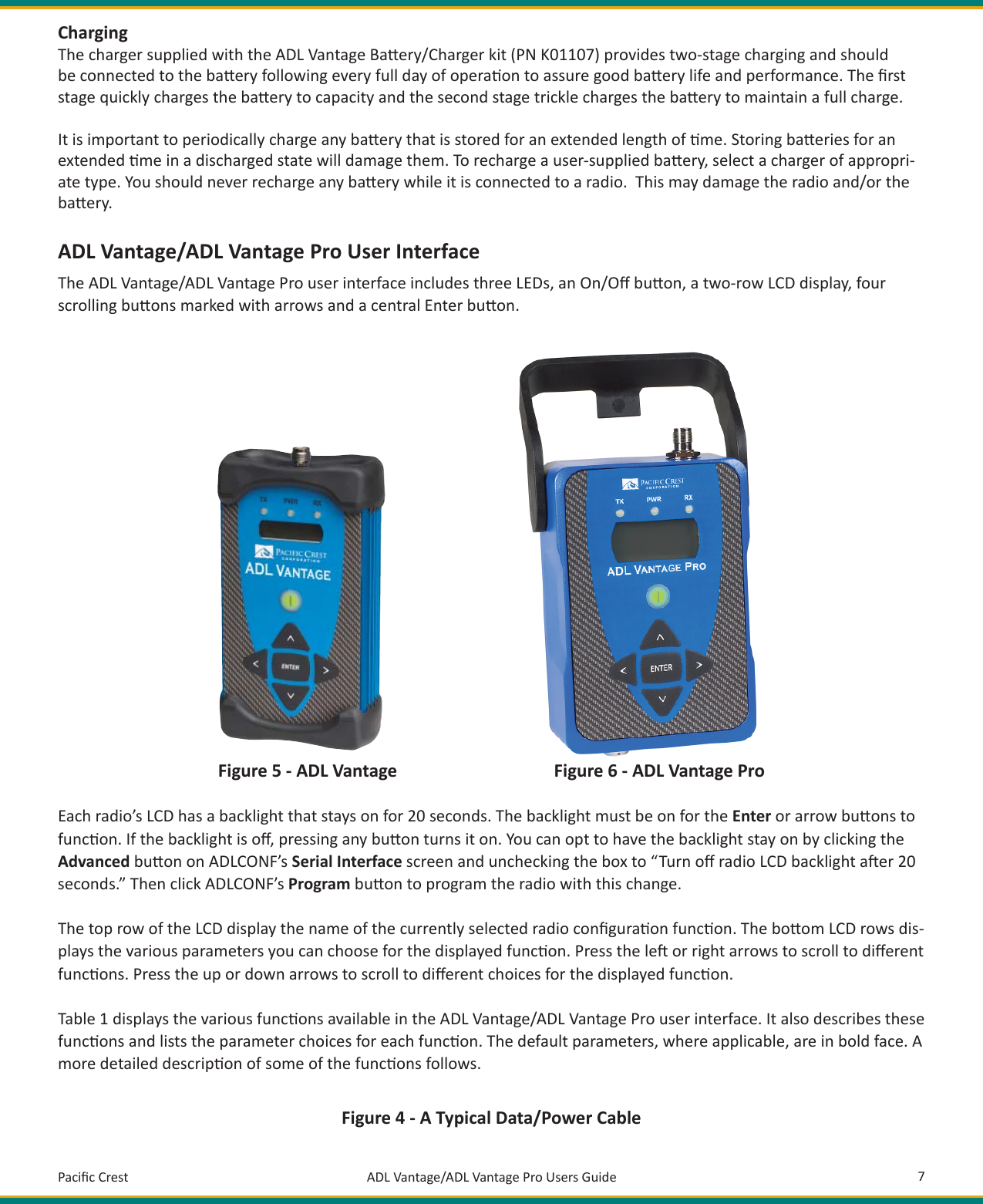

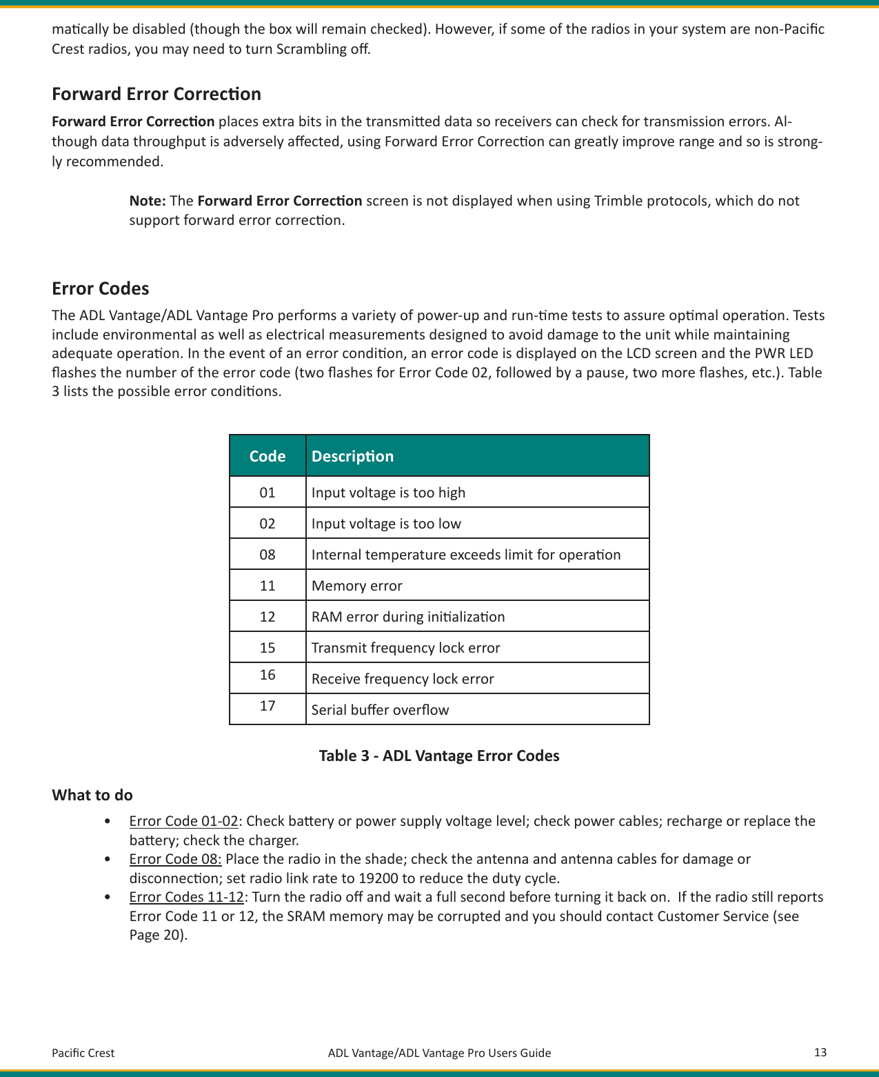
![Pacifi c Crest ADL Vantage/ADL Vantage Pro Users Guide 14• Error Codes 15-16: If you are using the radio as a repeater, make sure that the transmit and receive frequencies are less than 10 MHz apart. Otherwise, you should return the radio for service. If the radio displays Error Code 15 (Transmit frequency lock error), it is important to stop using it because the crystal oscillator might be unstable and you might be transmi ng at an unprogrammed frequency for which you are not licensed. • Error Code 17: If data comes into the radio faster than it can be transmi ed, the serial buff er can overfl ow. If the radio displays Error Code 17, you should adjust the serial baud rate and radio link rate so the radio has enough me to transmit each data packet before the next packet is sent to the radio.If the radio con nues to display the error code a er you have fi xed the situa on, you may clear the error code from the radio’s display by pressing the On/Off bu on for 3 seconds (turning off the radio), wai ng one full second and pressing the On/Off bu on a second me. If an error warning persists, contact a Pacifi c Crest authorized dealer or Pacifi c Crest Customer Support.RF Output Power Regula onExcessive heat is the enemy of all electronic equipment. For this reason ADL radios are equipped with RF (Radio Frequen-cy) output power regula on fi rmware. Both the ADL Vantage and ADL Vantage Pro radios can operate safely with an am-bient temperature as high as 65 degrees [use the degree symbol] cen grade (150 degrees Fahrenheit). But if the radio detects an internal temperature rising close to the maximum, it will reduce its RF output power automa cally. While this reduces range temporarily, it also prevents damage to the radio that might cause a permanent loss of range.If the ADL Vantage senses its internal temperature approaching the limit while it is set to transmit at its maximum 4 Wa s, the radio will reduce its output power to 2 Wa s. If the temperature con nues to rise at the 2 Wa se ng, the radio will turn off its transmi er completely. The radio will stay on and will display a “High Temp” message on its LCD screen. When the internal temperature decreases suffi ciently, the RF output power will automa cally increase. Any automa c change in the power se ng - either a decrease or an increase - is preceded by a message sent to the receiver radio(s) informing them of the change. Other ADL Vantage or ADL Vantage Pro radios will display this message to the user on their LCD displays and by fl ashing all three LEDs for 5 seconds.If the ADL Vantage Pro senses the internal temperature approaches the limit while it is set to transmit at its High transmit power (as programmed into the radio with ADLCONF confi gura on so ware), the radio will reduce its output power by 5 Wa s. If the temperature con nues to rise, the radio will reduce its output power by another 5-Wa s and so on un l the Medium transmit power level is met. The radio may then reset itself to output at the 2 Wa Low power se ng or shut off the transmi er. As with the ADL Vantage, RF power output will automa cally increase as the radio’s internal tem-perature decreases.If for some reason the ADL Vantage/ADL Vantage Pro radio’s internal temperature is ever exceeded, it will automa cally shut off the transmi er and display the Error 08 (excessive internal temperature). Shut the radio off , let it cool and turn it back on. If the storage temperature maximum has been exceeded, the radio will con nue to display the Error 08 and may require repair.](https://usermanual.wiki/Trimble-Navigation/ADLP/User-Guide-1396082-Page-17.png)