Trimble Navigation ADLP Advanced Data Link, Padre (ADLP) User Manual ADL Vantage ADL Vantage Pro Guide indd
Trimble Navigation Ltd Advanced Data Link, Padre (ADLP) ADL Vantage ADL Vantage Pro Guide indd
Users Manual

ADL Vantage/
ADL Vantage Pro
Users Guide

Pacifi c Crest ADL Vantage/ADL Vantage Pro Users Guide i
No ce
PACIFIC CREST MAKES NO WARRANTY OF ANY KIND WITH REGARD TO THIS MATERIAL, INCLUDING, BUT NOT LIMITED
TO, THE IMPLIED WARRANTIES OF MERCHANTABILITY AND FITNESS FOR A PARTICULAR PURPOSE. Pacifi c Crest shall
not be liable for errors contained herein or for incidental consequen al damages in connec on with the furnishing, per-
formance, or use of this material.
This document contains proprietary informa on that is protected by copyright. All rights are reserved. Adapta on, or
transla on of this manual is prohibited without prior wri en permission of Pacifi c Crest, except as allowed under the
copyright laws.
The informa on contained in this document is subject to change without no ce.
License required prior to opera on of radio communica on equipment.
Cau ons and Warnings
Throughout this manual this symbol is used to indicate cau on or warning. Please pay par cular a en on
to these items to assure safe and reliable opera on of your radio modem product.
Pacifi c Crest
510 DeGuigne Drive
Sunnyvale, CA 94085
(408) 481-8070
(408) 481-8984 Fax
info@Pacifi cCrest.com
www.Pacifi cCrest.com
December 2010
©2010 Pacifi c Crest. All rights reserved. PORON is a licensed trademark of Rogers Corpora on. SATEL is a registered
trademark of SATEL Oy. TRIMMARK and TRIMTALK are trademarks of Trimble Naviga on Ltd. All trademarks are the prop-
erty of their respec ve owners.
!

Pacifi c Crest ADL Vantage/ADL Vantage Pro Users Guide ii
Contents

Pacifi c Crest ADL Vantage/ADL Vantage Pro Users Guide 1
Introduc on
Welcome
Thank you for purchasing the Advanced Data Link (ADL) Vantage or Vantage Pro. The ADL Vantage™ and
ADL Vantage Pro radios are advanced, high speed, wireless data links that are designed specifi cally for
GNSS/RTK applica ons but are also appropriate for many other applica ons requiring digital data links.
Your success in using the ADL Vantage/ADL Vantage Pro is Pacifi c Crest’s primary goal. Pacifi c Crest stands
behind its products by providing expert support and service. Your comments and ques ons are welcome.
Scope
This guide provides informa on concerning the use of the ADL Vantage (Model Numbers ADLV-1 and
ADLV-2) and the ADL Vantage Pro (Model Numbers ADLP-1 and ADLP-2).. This guide is wri en for the
fi rst- me user and gives details concerning system setup, opera on and maintenance. We urge you to
take the me to review this short manual completely prior to se ng up your system.
Note Concerning this Guide
We believe that the ADL Vantage/ADL Vantage Pro systems provide the best value and performance for
the user. As such, we provide our equipment in complete turnkey systems, including all of the items nec-
essary for opera on with your GPS.
You may have purchased your ADL Vantage/ADL Vantage Pro from a third party. On occasion, the bun-
dled product provided by these sources may diff er from the kits provided directly from Pacifi c Crest. If
this guide does not accurately refl ect the equipment that you received, please contact your supplier for
specifi c instruc ons concerning the setup of items that diff er.
Features and Benefi ts
Compa ble
• Facilitates radio equipment mix and match
• Interoperable with Pacifi c Crest (RFM, PDL and ADL), SATEL, and Trimble radio products
• All models support 12.5 and 25 kHz channel bandwidth communica ons
• 40 MHz-wide channel tables (390-430 and 430-470 MHz models)
• Provides upgrade path for exis ng installa ons
Enhanced User Interface
• Backlit LCD display and fi ve-bu on naviga on interface
• View and change radio channel, modula on and protocol types
• Monitor signal levels, baud rates, and other parameters
Fast Over-the-Air Data Rate
• 19,200 bits per second
• Reduced latency provides be er GNSS posi on informa on
• Shorter transmit mes reduces power consump on for longer ba ery life

Pacifi c Crest ADL Vantage/ADL Vantage Pro Users Guide 2
User-selectable RF output
ADL Vantage: Select between 0.1. 0.5, 1, 2 and 4 Wa s
ADL Vantage Pro: Select between low power (2 Wa s), three intermediate power se ngs and high
power (as high as 35 Wa s)
• Increase range by switching to a higher transmit power
• Increase ba ery life by reducing transmit power when you don’t need the range
Rugged Construc on
Designed specifi cally for real-world working environments
• All metal construc on and shock mounted electronics ensure highest reliability and EMI-
resistance
• Water ght, corrosion-resistant connectors stand up to bad weather condi ons
Confi guring ADL Vantage/ADL Vantage Pro
ADLCONF Confi gura on So ware
ADLCONF is a suite of so ware u li es for confi guring and troubleshoo ng Pacifi c Crest’s Advanced Data
Link (ADL) line of digital communica on radios and modems. Running ADLCONF on a PC a ached via
serial cable to an ADL radio allows you to check the status of the radio, input receive-only channel tables,
and set radio parameters such as channel bandwidth and output power. Channel tables for transmission
of data must be obtained from authorized Pacifi c Crest dealers. If your radio did not come with a channel
table already installed, you can obtain one from your dealer and import it using ADLCONF.
ADLCONF is a so ware applica on for confi guring all ADL radios. The latest version is available for free
download from www.Pacifi cCrest.com. A user guide that completely describes how to confi gure ADL
radios is available by running ADLCONF and clicking Help > User Guide. The ADLCONF User’s Guide is also
available on the Pacifi c Crest website.
Factory Default Se ngs
You can return your ADL Vantage/ADL Vantage Pro radio to its factory default confi gura on using ADL-
CONF so ware. Simply click the Restore Factory bu on to the right of the screen and then the Program
bu on. The factory default se ngs are described in are described in Table 1 on pages 8-9.
Se ng Up the ADL Vantage/ADL Vantage Pro
The ADL Vantage/ADL Vantage Pro Offi ce Accessory Kits
The ADL Vantage/ADL Vantage Pro Offi ce Accessory Kits consists of the following:
• Wall/mains power supply
• Wall plug with adaptor set
• Programming cable
Pacifi c Crest ADL Vantage/ADL Vantage Pro Users Guide 3
To confi gure the radio with ADLCONF so ware:
• Connect the power supply to the wall/mains current
• Connect the programming cable to:
The power supply
The ADL Vantage/ADL Vantage Pro radio
Your PC (If your PC does not have a serial port, you may use a serial-to-USB adaptor)
• Turn on the radio
• Launch ADLCONF so ware and refer to the sec on of the ADLCONF User’s Guide on
connec ng the program to your radio. In most cases, you just need to click ADLCONF’s
Con nect bu on.
To operate your ADL Vantage/ADL Vantage Pro radio in the fi eld you will need an antenna, a portable
power supply and a cable to connect to a data source such as a GNSS receiver. Pacifi c Crest and its au-
thorized dealers can provide you with everything you need including a tripod accessory kit and a ba ery/
charger kit.
Tripod Mounts
Each ADL Vantage includes a tripod clip on the rear of the radio (see Figure 1). Insert the clip into a slot
on the tripod.
Figure 1 – ADL Vantage Tripod Clip
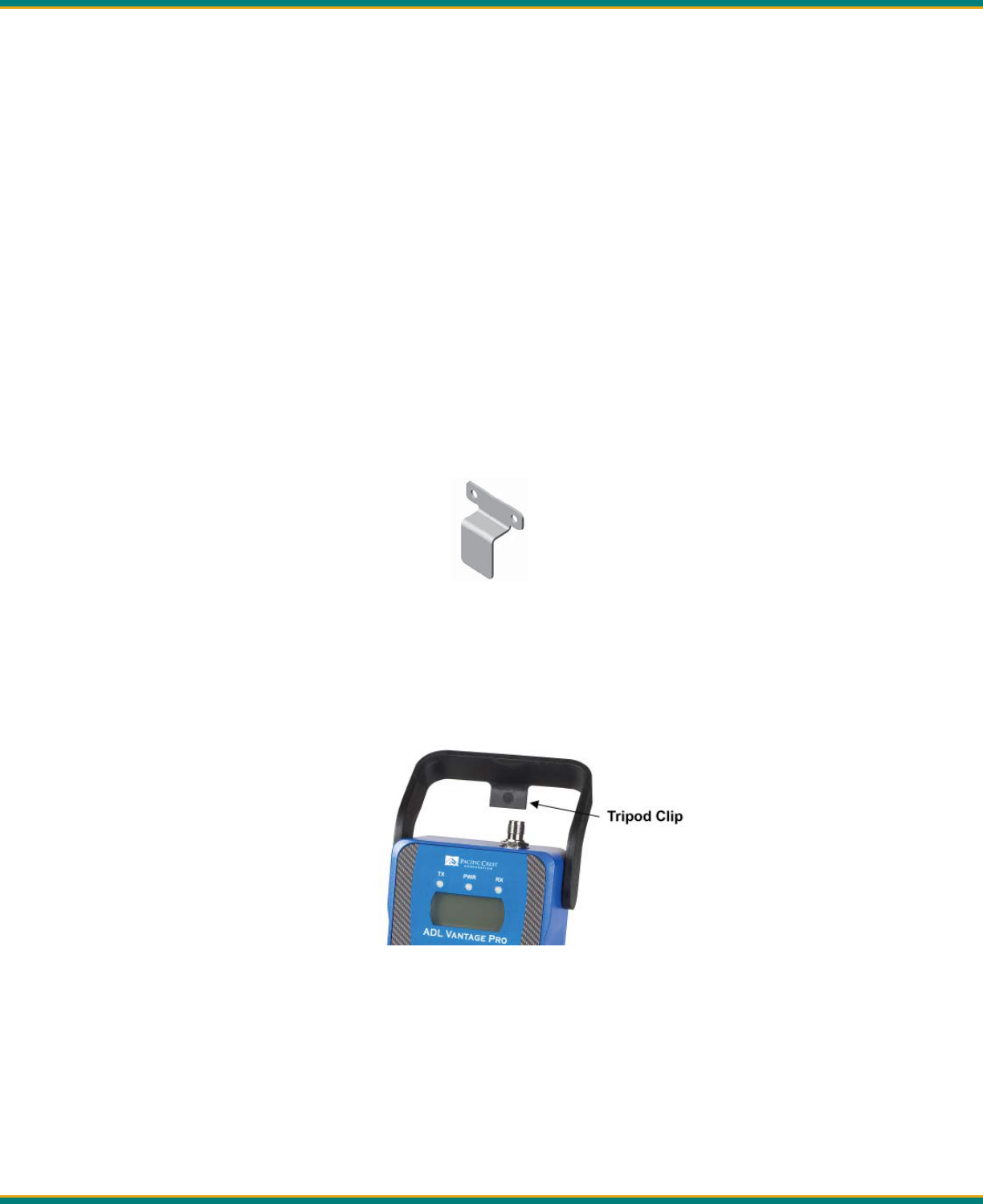
Each ADL Vantage Pro includes a high-impact polymer handle with built-in tripod clip (see Figure 2).
Insert the clip into a slot on the tripod.
Figure 2 – ADL Vantage Pro Handle with Tripod Clip
Pacifi c Crest ADL Vantage/ADL Vantage Pro Users Guide 4
Antenna and Antenna Mount
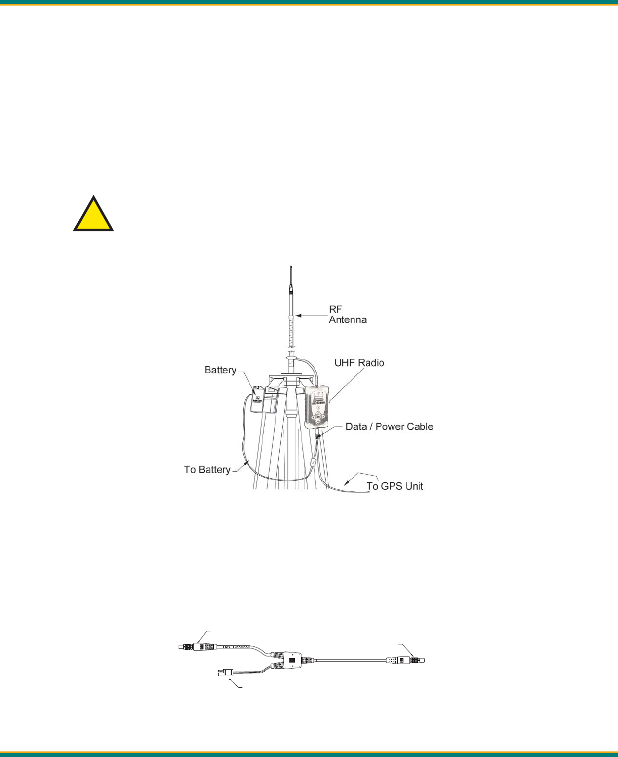
If you have an antenna with a male TNC connector, you can a ach it directly to the RF connector on the
top of the ADL Vantage/ADL Vantage Pro. We highly recommend, however, that you elevate your RF an-
tenna as much as possible. The most common set up is similar to that seen in Figure 3 where an antenna
cable with male TNC connector is a ached to the radio. The other end of this cable is a ached to a
tripod or elevated sec on of range pole. The RF antenna is then a ached to the end of the cable. Pacifi c
Crest off ers an antenna cable that a aches to standard 5/8-inch threaded tripods and range poles and
antennas with NMO connectors.
We recommend inspec ng the antenna center push-pin contact to make sure that it makes good contact
with the antenna mount. A good antenna connec on is cri cal to system performance.
Always make sure an antenna is connected before transmi ng with any radio. A good fi eld
prac ce is to a ach the antenna before you turn on the radio and turn off the radio before
you detach the antenna. Using a gained antenna will raise the Eff ec ve Isotropic Radiated
Power of the ADL Vantage/Vantage Pro radio. Make sure the resultant Eff ec ve Isotropic
Radiated Power does not exceed your licensed limit.
Figure 3 - ADL Vantage/ADL Vantage Pro Setup
Data/Power Cable
The ADL Vantage/ADL Vantage Pro radios are connected to a data source, such as a GNSS receiver, using
a data/power cable (see Figure 4). These cables are available with diff erent connectors for a aching to a
large variety of data sources. Contact your Pacifi c Crest sales representa ve for selec ng the best cable
to meet your needs.
!
Data Source Connector
Radio Connector
SAE Power Connector

Pacifi c Crest ADL Vantage/ADL Vantage Pro Users Guide 5
Each ADL data/power cable also connects the radio (and in some cases the data source) to external power via an SAE-
type connector. Pacifi c Crest strongly recommends you use the ADL Vantage external ba ery (PN A01742) or the ADL
Vantage Pro external ba ery (PN A00399), both of which include an SAE connector. These are sold both separately and
as part of the ba ery/charger kits (ADL Vantage, PN K01107; ADL Vantage Pro, PN tbd).
NOTE: Do NOT use any ba ery charger as a power supply for any Pacifi c Crest radio. This may damage
the radio. Do NOT recharge any ba ery while it is connected to a radio.
Opera ng the ADL Vantage/Vantage Pro
Turning the Radio On and Off
Warning: The ADL Vantage Pro enclosure and heat sink may become very hot during oopera on, depend-
ing on the air temperture, RF power selec on and transmission duty cycle. Turn off the radio and allow it
to cool prior to handling. Always use the heat-resistant handle to hold or move the ADL Vantage Pro.
To turn on the ADL Vantage or ADL Vantage Pro, a ach the radio to its ba ery via the SAE connector on either the pro-
gramming cable or data/power cable. Once the radio detects power on its data connector, it will turn on automa cally,
test the antenna connec on and ba ery status, and be ready for communica on within 5 seconds. If wall/mains current
is ever interrupted, the ADL Vantage/ADL Vantage Pro radio will automa cally turn itself on and resume transmi ng
data within 5 seconds of power restora on. To turn off the radio, either detach its power cable or press the On/Off but-
ton in the center of the front panel. You may turn the radio on again either by pressing the On/Off bu on or by remov-
ing and reinser ng the data/power cable.
Indicator LEDs
The TX LED indicates that the ADL Vantage/ADL Vantage Pro is broadcas ng. In most GPS RTK applica ons, the TX LED
will fl ash approximately once per second.
The PWR LED is illuminated when power between 9 and 30 VDC is supplied to the radio. When more than 30 VDC are
supplied, all three LEDs will fl ash indica ng Error Code 01 for a high voltage condi on. If less than 9 VDC are supplied,
all three LEDs will fl ash twice, pause, fl ash twice, pause, etc., indica ng Error Code 02 for a low voltage condi on. o
provides a low external voltage supply indicator. When lit, power is turned on. The PWR LED will blink when the external
voltage drops to a level determined using ADLCONF so ware. (The default level is 10 VDC.) If the PWR LED does not turn
on/off when pressing the On/Off bu on on the radio’s front panel, inspect the external voltage supply. The minimum
voltage required by the ADL Vantage/ADL Vantage Pro is 9 VDC.
The RX LED fl ashes to indicate that the ADL Vantage/ADL Vantage Pro is receiving signals from another radio or from
a source of interference. The default is Signal received, but you can reset the radio so that when its RX LED fl ashes it
means Data packets received. You can reset the meaning either through the user interface or with ADLCONF confi gura-
on so ware. During normal opera on, the RX LED will fl ash at a once-per-second rate indica ng the recep on of trans-
missions from the transmi ng radio. If the RX LED is on con nuously, then a source of interference may be impac ng
the ability of the ADL Vantage to receive data. Try reposi oning the antenna, or changing to another channel at both the
transmi er and receiver to reduce or eliminate the interference.
Enclosure
The ADL Vantage enclosure is made from a tough, impact-resistant aluminum alloy. The enclosure receives an an -corro-
sion treatment and is further protected with a chemical- and scratch-resistant polyurethane coa ng. Elastomer end caps
!
!
Pacifi c Crest ADL Vantage/ADL Vantage Pro Users Guide 6
provide the fi rst level of shock protec on for the internal components. An internal isola on system reduces the eff ec
t
of vibra on on the radio receiver board.
Antenna Connector
The ADL Vantage/ADL Vantage Prod radios use an industry standard TNC-female RF connector that is compa ble with
wide range of mobile whip antennas. Pacifi c Crest also sells cables that connect the ADL Vantage to remote antennas.
Ba ery Care
The ADL Vantage Ba ery/Charger kit (PN K01107) includes a 12-Volt, 12-AHr, deep-discharge, lead-acid ba ery. The
A
Vantage Pro Ba ery/Charger kit (PN 81818) includes a 12-Volt, 33-AHr, deep-discharge, lead-acid ba ery. Both ba er
-
ies provide all-day opera on for the respec ve radios and may be recharged approximately 300 mes over a period o
years.
To power the ADL Vantage with a user-supplied ba ery, select a deep-discharge ba ery with a minimum capacity of
8
AHr. Ba eries designed for automo ve use can be used if necessary but will be damaged by repe ve discharge/char
cycles and are therefore not recommended.
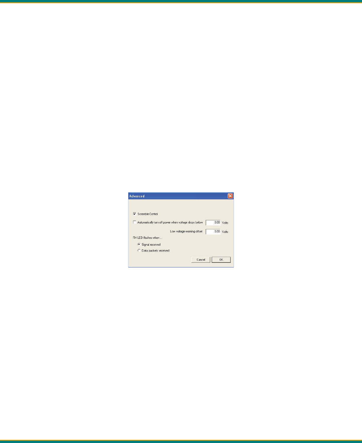
By default, the ADL Vantage/ADL Vantage Pro user interface displays ba ery status on the bo om row of the Device
Status screen. The screen displays “Normal” un l the voltage on the ba ery falls below a level input on ADLCONF by
clicking the Advanced bu on on the Radio Link screen.
To prevent ba ery damage, the ADL Vantage automa cally shuts itself off when the input voltage drops below 9 Volts
(see Figure 7). The ADL Vantage Pro radio shuts itself off automa cally when the input voltage drops below 9.5 Volts. You
can input a diff erent value on the Radio Link/Advanced screen, but inpu ng a value less than 9 V (ADL Vantage) and 9.5
V (ADL Vantage Pro) is not recommended. To confi gure the radio to warn you when you are within a number of volts of
this minimum voltage, input a value into the Low voltage warning off set fi eld. For example, with the radio programmed
with 9.5 and 1.00 in the voltage fi elds, the PWR LED on the front of the radio will begin fl ashing when the input voltage
drops to 10.5 Volts (9.5 + 1.00).
ADLCONF and its user guide are available for free download at www.Pacifi cCrest.com.
You can turn this ba ery protec on feature off , but the ADL Vantage/ADL Vantage Pro radios will not transmit with an
input voltage lower than 9 VDC. To run your radio as a receiver at voltages as low as 5 VDC, uncheck the box illustrated in
Figure 7 and program the radio.
Figure 7 - ADLCONF’s Radio Link/Advanced Screen
Pacifi c Crest ADL Vantage/ADL Vantage Pro Users Guide 7
Charging
The charger supplied with the ADL Vantage Ba ery/Charger kit (PN K01107) provides two-stage charging and should
be connected to the ba ery following every full day of opera on to assure good ba ery life and performance. The fi rst
stage quickly charges the ba ery to capacity and the second stage trickle charges the ba ery to maintain a full charge.
It is important to periodically charge any ba ery that is stored for an extended length of me. Storing ba eries for an
extended me in a discharged state will damage them. To recharge a user-supplied ba ery, select a charger of appropri-
ate type. You should never recharge any ba ery while it is connected to a radio. This may damage the radio and/or the
ba ery.
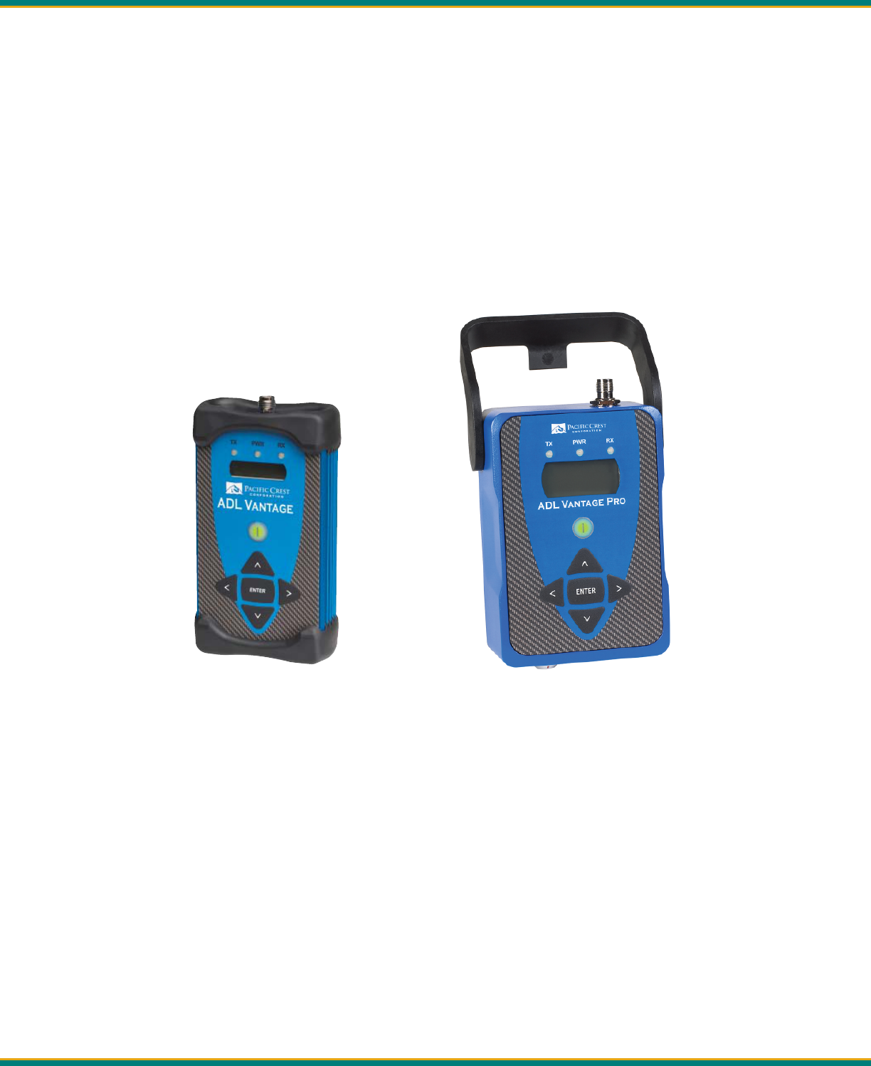
ADL Vantage/ADL Vantage Pro User Interface
The ADL Vantage/ADL Vantage Pro user interface includes three LEDs, an On/Off bu on, a two-row LCD display, four
scrolling bu ons marked with arrows and a central Enter bu on.
Figure 5 - ADL Vantage Figure 6 - ADL Vantage Pro
Each radio’s LCD has a backlight that stays on for 20 seconds. The backlight must be on for the Enter or arrow bu ons to
func on. If the backlight is off , pressing any bu on turns it on. You can opt to have the backlight stay on by clicking the
Advanced bu on on ADLCONF’s Serial Interface screen and unchecking the box to “Turn off radio LCD backlight a er 20
seconds.” Then click ADLCONF’s Program bu on to program the radio with this change.
The top row of the LCD display the name of the currently selected radio confi gura on func on. The bo om LCD rows dis-
plays the various parameters you can choose for the displayed func on. Press the le or right arrows to scroll to diff erent
func ons. Press the up or down arrows to scroll to diff erent choices for the displayed func on.
Table 1 displays the various func ons available in the ADL Vantage/ADL Vantage Pro user interface. It also describes these
func ons and lists the parameter choices for each func on. The default parameters, where applicable, are in bold face. A
more detailed descrip on of some of the func ons follows.
Figure 4 - A Typical Data/Power Cable

Pacifi c Crest ADL Vantage/ADL Vantage Pro Users Guide 8
Func on Descrip on Parameter Choices
Device Status Displays radio status and iden fi ca on informa on Ba ery status
Owner name
Call sign
Modula on type
Channel bandwidth
Transmi er status
Firmware version
Channel / Freq Displays/selects channel number & receive frequency Channel 01 and frequency (MHz)
Channel 02 and frequency (MHz)
Etc.
Ch TX Freq Displays TX freq (if diff erent from the channel’s RX freq) Channel No. & frequency (MHz)
Data Protocol Displays/selects data protocol type Trans EOT (End of Transmission)
Trans EOC (End of Character)
Packet Switched
TRIMTALK 450S
TRIMMARK II/IIE
TT450S (HW)
TRIMMARK 3
SATEL®
Trans FST
Radio Link Rate Displays/selects bit rate for radio transmission/recep on 4800
8000
9600
16000
19200
Repeater Mode Sets the radio to be a repeater (non-Trimble) protocols) Off (Not a repeater)
On (Is a repeater)
Opera on Mode Sets the radio to be a repeater (Trimble protocols) Base/Rover
Base w/ One Rpt
Base w/Two Rpt
Repeater1
Repeater2
Sensi vity Displays/selects radio squelch level High (Rover)
Moderate
Low (Base)
Transmit Power Displays/selects transmi er power level (in Wa s) Low Power
Pacifi c Crest ADL Vantage/ADL Vantage Pro Users Guide 9
Low intermediate power
Intermediate power
High intermediate power
High power
RX LED Meaning Displays/selects what it means when the RX LED fl ashes Signal Received
Data Received
Serial Baud Displays/selects serial baud rate of the radio’s data port 2400
4800
9600
19200
38400
115200
Signal Strength Displays strength of the received signal (RSSI) in dBm Press Enter
Advanced Menus Displays or Conceals rarely used func ons Hide
Show
CSMA Displays/selects Carrier Sense Mul ple Access se ng On
Off
Security Code Encrypts/Decrypts transmi ed data Off
On
Edit
Confi gura on Enables/Disables confi gura on using the radio interface Enabled
Disabled
Scrambling Fills dead air with non-zero bits On
Off
FEC Turns Forward Error Correc ons on/off On
Off
Error Code Displays current error status Error (if any)
Language Select
(ADL Vantage Pro
Only)
Selects the display language English
Chinese
Russian
Table 1- ADL Vantage/ADL Vantage Pro User Interface Display

Pacifi c Crest ADL Vantage/ADL Vantage Pro Users Guide 10
The ADL Vantage and ADL Vantage Pro LCDs display radio parameters that are determined:
• In the factory: serial number, fi rmware version, transmi er status (enabled/disabled)
• By the radio: ba ery status, signal strength and error codes
• By your dealer: channel tables (including frequency and bandwidth) and maximum transmit power
• In the offi ce using the ADLCONF program (everything else)
In addi on, you may confi gure the following parameters in the fi eld using the ADL Vantage/Vantage Pro user interface:
• Channel number
• Data protocol
• Radio link rate
• Repeater Mode (called “Opera on Mode” when using a Trimble protocol)
• Sensi vity
• Transmit power
• RX LED meaning
• Serial baud rate
• CSMA (Note: It is illegal to transmit in the United States while CSMA is turned off . CSMA should be turned off
within the European Union.)
• Security Code
• Edit Confi gura on
• Scrambling
• Forward Error Correc on
• Language of display (with ADL Vantage Pro only)
For the fi eld-confi gurable func ons, the available choices are displayed on the bo om row of the LCD. The currently
selected parameter is marked with an asterisk. To select a diff erent choice for the displayed func on, scroll up or down
with the arrow bu ons and press the Enter bu on when the desired choice is displayed.
There are two ways to move to a diff erent func on screen. When viewing a display-only func on such as Device Status
or Signal Strength, simply press the le or right arrow. When viewing a display-and-select func on such as Channel/Freq
or Data Protocol, fi rst press the up/down arrows to display the currently selected parameter (marked with an asterisk) in
the second row. Then press either the le or right arrow to move to a new func on screen.
Note: if the currently selected parameter (shown with an asterisk) is not currently displayed on the LCD,
and the backlight is off , you have not pressed a bu on for more than 20 seconds), you can scroll directly to
the selected parameter by pressing the le or right arrow once. To move to a new func on screen, press
the le or right arrow a second me.
To speed fi eld confi gura on and to prevent the selec on of unsupported radio confi gura ons, the ADL Vantage/ADL
Vantage Pro user interface displays only those func on parameters that make sense based on the parameters chosen for
previously displayed func ons. What you choose for the data protocol determines your op ons for radio link rate and
repeater mode. For example, if your channel table is set to 12.5 kHz channel spacing, and you select TT450S (HW) on
the Data Protocol screen, you cannot select a radio link rate – in fact the Radio Link Rate screen does not even appear -
because the TT450S (HW) protocol works with 12.5 kHz channel spacing only at 4800 bps. And because TT450S (HW) is a
Trimble protocol, Trimble-specifi c “Opera on Modes” (instead of “Repeater Modes”) are available for selec on. The ADL
Vantage/ADL Vantage Pro user interface remembers things like this so you don’t have to! If you decide to undo any of
these selec ons, simply press the le arrow to return to the Data Protocol screen and select a diff erent protocol.
Although the ADL Vantage/ADL Vantage Pro radio modem supports both GMSK and 4FSK modula on, you cannot select
the modula on type with the user interface. The radio automa cally selects the appropriate modula on based on the
channel bandwidth of the radio’s channel table (displayed on the Device Status screen as “BW: 12.5 or 25 kHz”), the data

Pacifi c Crest ADL Vantage/ADL Vantage Pro Users Guide 11
protocol and the radio link rate. If you want to select a modula on type fi rst and then an appropriate channel band-
width, protocol and link rate, please use ADLCONF to confi gure the radio.
Tips and Techniques for Best Performance
Antenna
Antenna placement is cri cal for good performance. Range and coverage is directly propor onal to the height of the
transmi ng and receiving antennas in addi on to antenna gain. Where possible, select a reference sta on loca on that
takes advantage of terrain to get the transmi ng antenna as high as possible.
Always use the telescoping antenna mast and raise the antenna as high as is prac cal and safe given terrain and wind
condi ons.
Do not use a gained antenna if doing so increases the radio’s Eff ec ve Isotropic Radiated Power beyond the limit of your
license.
Line Loss
Line loss from connectors and cables between the radio and antenna decreases the output power transmi ed by the
antenna, thereby decreasing the signal’s range. To minimize line loss, please check the loss-per-length of cable to be
used. For every 3 dB of line loss, the ERP (Eff ec ve Radiated Power) will decrease by half. For example, if you have a 4
W radio and a line loss of 3 dB in your cable and antenna, the power eff ec vely radia ng from the antenna will be 2 W.
Every 6 dB of loss will reduce the radio’s eff ec ve range by 50%.
Power Supplies
Maintain ba eries in a fully charged state. They will last longer if they are not allowed to become completely discharged.
We recommend rou nely connec ng the ba ery to its charger a er every working day and for 24 hours every 3 months
during period of non-use. This will assure op mal performance and long ba ery life.
Equipment Care
Rou ne equipment care will prolong the life and reliability of your ADL Vantage. Radio communica on equipment is
suscep ble to damage from shock or environmental extremes. Never operate the ADL Vantage outside the opera ng-
specifi ca ons contained in Appendix C.
CSMA (Carrier Sense Mul ple Access)
CSMA is a technology implemented in ADL Vantage/ADL Vantage Pro radios to meet the United States Federal Commu-
nica on Commission (FCC) transmi er requirements. It is illegal to transmit on any UHF radio within the United States
without CSMA enabled. CSMA holds off the radio transmission if the frequency is currently being used by a co-channel
user. On occasion, you may note that the radio broadcasts stop for short periods of me. Most o en, this is a case of
co-channel interference and the ADL Vantage/ADL Vantage Pro radio is holding off broadcasts due to the FCC-mandated
CSMA.
Note: You should turn CSMA off when transmi ng within the European Union.

Pacifi c Crest ADL Vantage/ADL Vantage Pro Users Guide 12
GPS RTK equipment is designed to func on with intermi ent gaps in the data. Heavy co-channel use may limit the ability
of the ADL Vantage/ADL Vantage Pro radio to transmit the required informa on. In areas of heavy co-channel usage, try
changing channels to a less used frequency.
Security Code
You can use the ADLCONF so ware program to confi gure your ADL Vantage/ADL Vantage Pro to send and receive en-
crypted data. When the radio is programmed for encryp on, the second line of its Security Code screen will say On (with
an asterisk). Only radios that support Pacifi c Crest protocols (Transparent EOT, Transparent EOC, Packet Switched) and are
programmed with this code will be able to interpret data sent by any of the radios. To turn the security code feature off ,
press the Up or Down arrow to display the Off op on and press Enter. to turn the security feature back on, select the On
op on. If the radio has not been programmed by ADLCONF for data security, you will not be able to select the On op on.
Note: If you program a radio to use the Data Security feature, it will not be able to communicate with any
radio that is not set to use the same code. So when you enable this feature for one radio it is a good idea to
enable it for all the radios you will use in the same communica on network. ADL radios with bu on/LCD
interfaces can turn the Data Security feature on or off in the fi eld, but all other Pacifi c Crest radios must be
returned to the offi ce to disable the Data Security feature using the appropriate confi gura on so ware.
Edit Confi gura on
The ADL Vantage/ADL Vantage Pro LCD display includes an Edit Confi g screen that indicates if confi guring the radio with
the keypad is Enabled or Disabled. The current selec on is displayed with an asterisk on the second row of the Edit
Confi g screen. To switch the selec on, press the down arrow to display the other op on and press the Enter bu on.
You are now instructed to input a passcode, which is 369369 for all ADL radios. To input this code, press the right arrow
to display a 3 on the second row. Then press the down arrow to display a 6 and the le arrow to display a 9. Press the
right, down and le bu ons a second me in sequence. When you see 369369 displayed on the second row of the LCD,
press Enter and the keypad’s ability to confi gure the radio is changed. You can also use ADLCONF to enable/disable the
Edit Confi g func on in the ADL Vantage/ADL Vantage Pro by checking/unchecking the Enable fi eld confi gura on box on
the Serial Interface screen’s Advanced menu. The RX LED fl ashes to indicate that the ADL Vantage/ADL Vantage Pro is
receiving signals from another radio or from a source of interference. The default is Signal received, but you can reset the
radio so that when its RX LED fl ashes it means Data packets received. You can reset the meaning either through the user
interface or with ADLCONF confi gura on so ware. During normal opera on, the RX LED will fl ash at a once-per-second
rate indica ng the recep on of transmissions from the transmi ng radio. If the RX LED is on con nuously, then a source
of interference may be impac ng the ability of the ADL Vantage to receive data. Try reposi oning the antenna, or chang-
ing to another channel at both the transmi er and receiver to reduce or eliminate the interference, another radio or
from a source of interference. The default is Signal received, but you can reset the radio so that when its RX LED fl ashes
it means Data packets received. You can reset the meaning either through the user interface or with ADLCONF confi gu-
ra on so ware. During normal opera on, the RX LED will fl ash at a once-per-second rate indica ng the recep on of
transmissions from the transmi ng radio. If the RX LED is on con nuously, then a source of interference may be impact-
ing the ability of the ADL Vantage to receive data. Try reposi
oning the antenna, or changing to another channel at both
the transmi er and receiver to reduce or eliminate the interference.
Scrambling
To demodulate a digital transmission, a receiver must synchronize itself with the transmi er. This can be hard to do when
the transmi er sends a long series of one’s or a long series of zeroes. But if every nth character in the transmission were
switched, a one to a zero or a zero to a one, and if the receiver was expec ng this, it could more quickly synchronize
itself with the transmission. This is essen ally what Scramble Control does and why we recommend you leave it on for
all radios. If you select a protocol type other than Transparent (EOT and EOC) or Packet Switched, Scrambling will auto-
Pacifi c Crest ADL Vantage/ADL Vantage Pro Users Guide 13
ma cally be disabled (though the box will remain checked). However, if some of the radios in your system are non-Pacifi c
Crest radios, you may need to turn Scrambling off .
Forward Error Correc on
Forward Error Correc on places extra bits in the transmi ed data so receivers can check for transmission errors. Al-
though data throughput is adversely aff ected, using Forward Error Correc on can greatly improve range and so is strong-
ly recommended.
Note: The Forward Error Correc on screen is not displayed when using Trimble protocols, which do not
support forward error correc on.
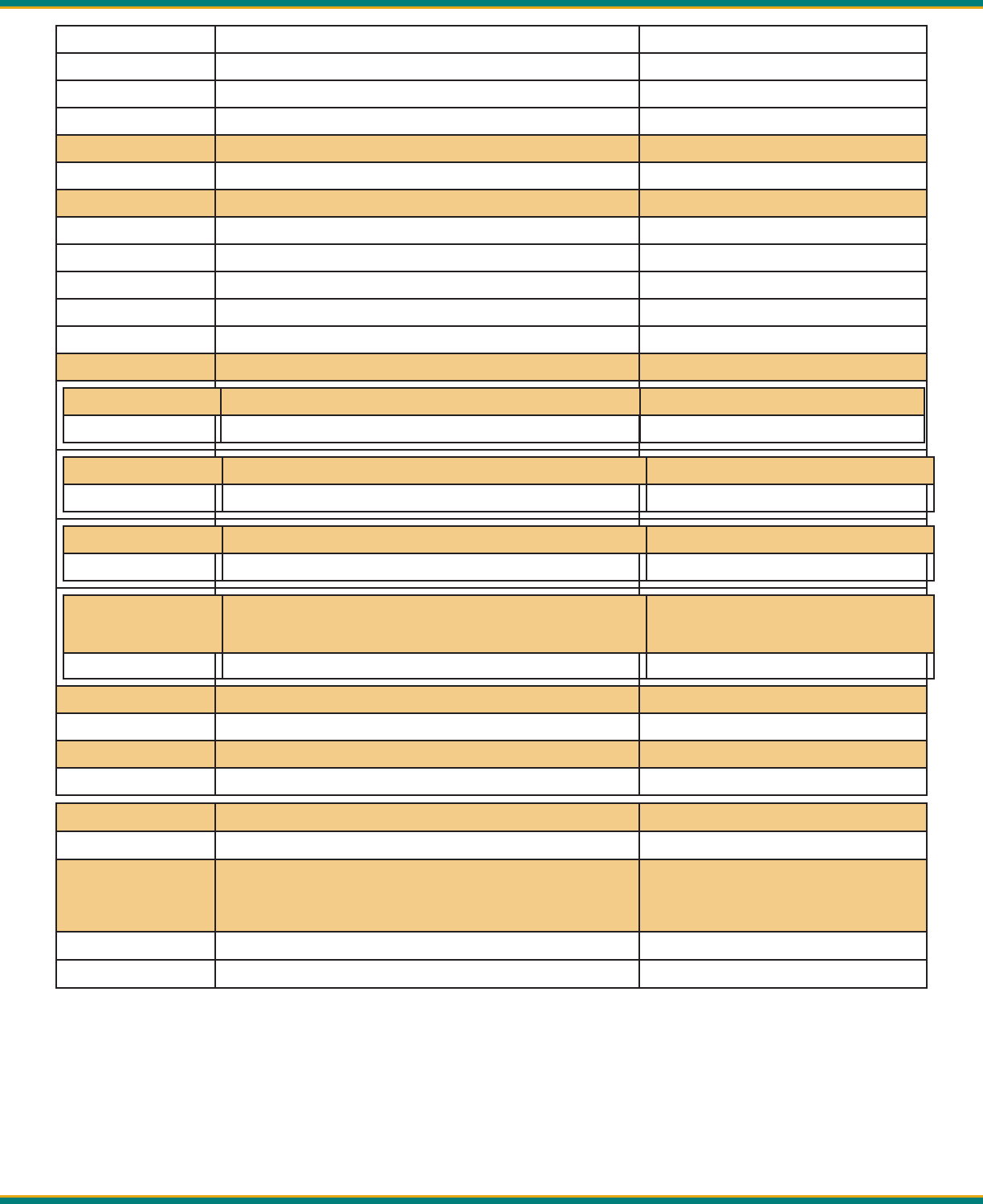
Error Codes
The ADL Vantage/ADL Vantage Pro performs a variety of power-up and run- me tests to assure op mal opera on. Tests
include environmental as well as electrical measurements designed to avoid damage to the unit while maintaining
adequate opera on. In the event of an error condi on, an error code is displayed on the LCD screen and the PWR LED
fl ashes the number of the error code (two fl ashes for Error Code 02, followed by a pause, two more fl ashes, etc.). Table
3 lists the possible error condi ons.
Code Descrip on
01 Input voltage is too high
02 Input voltage is too low
08 Internal temperature exceeds limit for opera on
11 Memory error
12 RAM error during ini aliza on
15 Transmit frequency lock error
16 Receive frequency lock error
17 Serial buff er overfl ow
Table 3 - ADL Vantage Error Codes
What to do
• Error Code 01-02: Check ba ery or power supply voltage level; check power cables; recharge or replace the
ba ery; check the charger.
• Error Code 08: Place the radio in the shade; check the antenna and antenna cables for damage or
disconnec on; set radio link rate to 19200 to reduce the duty cycle.
• Error Codes 11-12: Turn the radio off and wait a full second before turning it back on. If the radio s ll reports
Error Code 11 or 12, the SRAM memory may be corrupted and you should contact Customer Service (see
Page 20).

Pacifi c Crest ADL Vantage/ADL Vantage Pro Users Guide 14
• Error Codes 15-16: If you are using the radio as a repeater, make sure that the transmit and receive
frequencies are less than 10 MHz apart. Otherwise, you should return the radio for service. If the radio
displays Error Code 15 (Transmit frequency lock error), it is important to stop using it because the crystal
oscillator might be unstable and you might be transmi ng at an unprogrammed frequency for which you are
not licensed.
• Error Code 17: If data comes into the radio faster than it can be transmi ed, the serial buff er can overfl ow.
If the radio displays Error Code 17, you should adjust the serial baud rate and radio link rate so the radio has
enough me to transmit each data packet before the next packet is sent to the radio.
If the radio con nues to display the error code a er you have fi xed the situa on, you may clear the error code from the
radio’s display by pressing the On/Off bu on for 3 seconds (turning off the radio), wai ng one full second and pressing
the On/Off bu on a second me. If an error warning persists, contact a Pacifi c Crest authorized dealer or Pacifi c Crest
Customer Support.
RF Output Power Regula on
Excessive heat is the enemy of all electronic equipment. For this reason ADL radios are equipped with RF (Radio Frequen-
cy) output power regula on fi rmware. Both the ADL Vantage and ADL Vantage Pro radios can operate safely with an am-
bient temperature as high as 65 degrees [use the degree symbol] cen grade (150 degrees Fahrenheit). But if the radio
detects an internal temperature rising close to the maximum, it will reduce its RF output power automa cally. While this
reduces range temporarily, it also prevents damage to the radio that might cause a permanent loss of range.
If the ADL Vantage senses its internal temperature approaching the limit while it is set to transmit at its maximum 4
Wa s, the radio will reduce its output power to 2 Wa s. If the temperature con nues to rise at the 2 Wa se ng, the
radio will turn off its transmi er completely. The radio will stay on and will display a “High Temp” message on its LCD
screen. When the internal temperature decreases suffi ciently, the RF output power will automa cally increase. Any
automa c change in the power se ng - either a decrease or an increase - is preceded by a message sent to the receiver
radio(s) informing them of the change. Other ADL Vantage or ADL Vantage Pro radios will display this message to the
user on their LCD displays and by fl ashing all three LEDs for 5 seconds.
If the ADL Vantage Pro senses the internal temperature approaches the limit while it is set to transmit at its High transmit
power (as programmed into the radio with ADLCONF confi gura on so ware), the radio will reduce its output power by 5
Wa s. If the temperature con nues to rise, the radio will reduce its output power by another 5-Wa s and so on un l the
Medium transmit power level is met. The radio may then reset itself to output at the 2 Wa Low power se ng or shut
off the transmi er. As with the ADL Vantage, RF power output will automa cally increase as the radio’s internal tem-
perature decreases.
If for some reason the ADL Vantage/ADL Vantage Pro radio’s internal temperature is ever exceeded, it will automa cally
shut off the transmi er and display the Error 08 (excessive internal temperature). Shut the radio off , let it cool and turn
it back on. If the storage temperature maximum has been exceeded, the radio will con nue to display the Error 08 and
may require repair.

Pacifi c Crest ADL Vantage/ADL Vantage Pro Users Guide 15
FCC Rules and Regula ons
Licensing Requirements
It is the responsibility of the owner to comply with applicable rules and regula ons concerning the opera on of a radio
transmi er. In the United States, the FCC regulates the licensing of this equipment.
Applica on for a license is made by submi ng FCC Form 600 along with evidence of frequency coordina-
on (if required) and applicable fees. Similar licensing requirements exist worldwide. Penal es for broad-
cas ng without a license can be severe, and may include the confi sca on of your radio.
For more informa on, contact our customer service department.
Warning: Always obey local licensing requirements and restric ons. It is illegal to transmit in the United
States while CSMA is turned off . CSMA is not required within the European Union and should be turned off .
Equipment Compliances
ADL Vantage/ADL Vantage Pro have been tested and found to comply with Parts 15 and 90 of Title 47 of the Code of Fed-
eral Regula ons. ADL Vantage/ADL Vantage Pro radios have also been tested and found compliant for type cer fi ca on
and approval in many other countries worldwide.
For more informa on concerning our worldwide compliances, contact Pacifi c Crest Customer Service.
Being Part of the RF Community
Opera on of a licensed radio product makes you a member of the RF community. Be aware that virtually all frequencies
licensed are provided on a shared basis with other users. Each frequency dedicated specifi cally to RTK surveying ac vi-
es has certain restric ons and limita ons. For complete informa on, refer to the appropriate documenta on from the
licensing agency in your country of opera on, e.g., Part 90, Title 47, of the Code of Federal Regula ons.
Most frequencies sharing data transmissions and voice transmissions give priority to voice users. Be mindful of the
persistent nature of a GPS RTK data transmission and always limit your RF transmission output power when performing
close-in survey situa ons to avoid interference with co-channel users. Pacifi c Crest recommends using the low RF power
se ng for construc on site and other line-of-site surveys with baselines less than two miles (depending on terrain).
Warning: If you are in confl ict with a co-channel user, select another frequency to avoid formal ac ons by
geovernment agencies. In most cases you are required to vacate a frequency upon complaint by a shared
channel voice user.
Most survey opera ons are i nerant in that the system is moved on a frequent basis. For fi xed system installa ons, you
should not use frequencies set aside for i nerant opera ons, but should coordinate a frequency based on the fi xed area
opera on.
Regula ons diff er from country to country, so please be aware of the local regula ons prior to using radio equipment.
Automa c Sta on Iden fi ca on
For opera on in the United States, the FCC requires that radio transmi ers used for GPS RTK applica ons periodically
broadcast a sta on iden fi er. The sta on iden fi er is the call sign assigned to you on the sta on license.
!
!

Pacifi c Crest ADL Vantage/ADL Vantage Pro Users Guide 16
The ADL Vantage/ADL Vantage Pro support the broadcast of sta on iden fi ca on in a manner that meets the require-
ments of the FCC. Upon receipt of equipment, program your FCC call sign into the confi gura on of your ADL Vantage/ADL
Vantage using ADLCONF so ware. This is only required for transmi ers.
Warning: Failure to transmit your sta on iden fi ca on is in viola on of FCC regula ons. Use ADLCONF so -
ware to enter your FCC call sign.
!

Pacifi c Crest ADL Vantage/ADL Vantage Pro Users Guide 17
Contact Informa on
Customer Support
Quality, technology and service are the hallmarks of Pacifi c Crest. We provide easy access to our customer service de-
partment to keep you running effi ciently.
Headquarters EMEA Offi ce
Pacifi c Crest HAL Trade Center
510 DeGuigne Drive Bevelandseweg 150
Sunnyvale, CA 94085 1703 AX Heerhugowaard
USA The Netherlands
Tel: 1-800-795-1001 (U.S. & Canada toll free) Tel: +31-72-5348408
1-408-481-8070 (outside the U.S.) Fax: +31-72-5348288
Fax: 1-408-481-8984
E-mail: Support@Pacifi cCrest.com
Repair info: RMA Request
Web: www.Pacifi cCrest.com
Support hours are 8 AM to 5 PM Pacifi c Time. Please visit our website for up-to-¬date news and product announce-
ments. Firmware and so ware upgrades are available from our website, in most cases free of charge.
Sales Contact
Headquarters EMEA Offi ce
Pacifi c Crest HAL Trade Center
510 DeGuigne Drive Bevelandseweg 150
Sunnyvale, CA 94085 1703 AX Heerhugowaard
USA The Netherlands
Tel: 1-800-795-1001 (U.S. & Canada toll free) Tel: + 31-72-5348408
1-408-481-8070 (outside the U.S.) Fax: + 31-72-5348288
Fax: 1-408-481-8984
E-mail: Sales@Pacifi cCrest.com
Web: www.Pacifi cCrest.com

Pacifi c Crest ADL Vantage/ADL Vantage Pro Users Guide 18
Warranty
One-Year Limited Warranty
This warranty gives you specifi c legal rights. You may also have other rights which vary from state to state or area
to area.
Pacifi c Crest warrants ADL family products, inclusive of cables and ba eries, against defects in materials and
workmanship for a period of one year from receipt by the end-user.
Exclusions
Should Pacifi c Crest be unable to repair or replace the product within a reasonable amount of me, a refund of
the purchase price may be given upon return of the product.
The warranty on your ADL Vantage/ADL Vantage Pro shall not apply to defects resul ng from:
• Improper or inadequate maintenance by the customer
• Unauthorized modifi ca on, negligence or misuse
• Opera on outside of the environment specifi ca ons
Warranty Limita ons
This warranty set forth above is exclusive and no other warranty, whether wri en or oral, is expressed or implied.
Pacifi c Crest specifi cally disclaims the implied warran es of merchantability and fi tness for a par cular purpose.

Pacifi c Crest ADL Vantage/ADL Vantage Pro Users Guide 19
Appendix A - Safety Informa on
Exposure to Radio Frequency Energy
The ADL Vantage/ADL Vantage Pro is designed to comply with the following na onal and interna onal standards
and guidelines regarding exposure of human beings to radio frequency electromagne c energy, in addi on to
protec on against harmful interference of neighboring electrical equipment:
• FCC Report and Order FCC 96-326 (August, 1996)
• American Na onal Standards Ins tute (C95.3-1992)
• Na onal Council on Radia on Protec on and Measurement (NCRP - 1986)
• Interna onal Commission on Non-ionizing Radia on Protec on (ICNRP - 1986)
• European Commi ee for Electrotechnical Standardiza on (CENELEC)
• FCC CFR47 Part 15
• FCC CFR47 Part 90
• Industry Canada RSS 119
• ETSI EN 300 113-2
• ETSI EN 300 489
• ACA AS/NZS 4295
• iDA Spec 111
• OFTA STD-1E
• SRRC CMII
Contact your sales representa ve for model specifi c country approval.
To assure op mal radio performance and to ensure that exposure to RF energy is within the guidelines in the
above standards, the following opera ng procedures should be observed:
• Do not operate a transceiver when someone is within the distance noted below of the antenna
(unity gain).
120 cm (approx. 4 feet) for ADL Vantage Pro @ 35 Wa s
30 cm (approx. 12 inches) for ADL Vantage/ADL Vantage Pro @ 2 Wa s - 60 cm
(approx. 2 feet) for ADL Vantage/ADL Vantage Pro @ 4 Wa s
15 cm (approx. 6 inches) for ADL Vantage @ 1 Wa
• Do not operate the transceiver unless all RF connectors are secure and any open connectors
are properly terminated.
• Avoid contact with the antenna while opera ng the transceiver.
• Do not operate the transceiver with a damaged antenna. If a damaged antenna comes in contact
with the skin, a minor burn may result.
• Do not operate the equipment near electrical blas ng caps or in an explosive atmosphere.
Warning: Changes or modifi ca ons not expressly approved by the FCC could void the user’s author-
ity to operate the equipment.
Exposure to Hot Surfaces
The ADL Vantage Pro enclosure and heat sink may become very hot during opera on, depending on the air
temperature, transmit power and transmission duty cycle. Turn off the unit and allow it to cool prior to handling.
Always use the heat-resistant handle to hold or move the ADL Vantage Pro.
!
Pacifi c Crest ADL Vantage/ADL Vantage Pro Users Guide 20
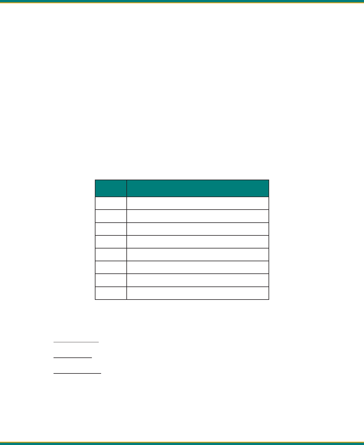
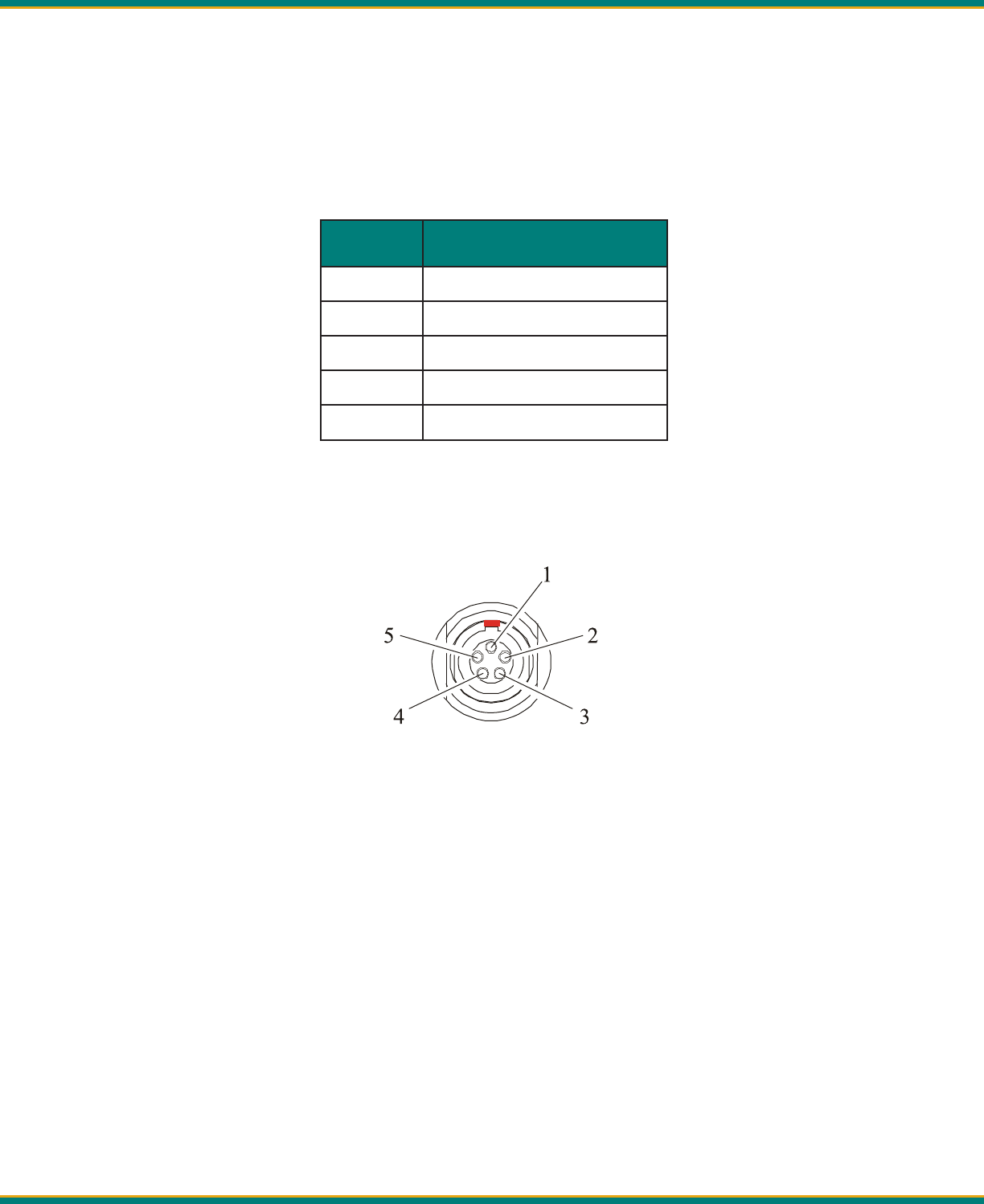
Appendix B - Pin-outs and Connectors
The ADL Vantage/ADL Vantage Pro uses a #1-shell, 5-pin circular data/power connector. For a ma ng connector,
Pacifi c Crest recommends using a LEMO P/N FGG.1B.305.CLAD.72Z, or equivalent. Refer to Table 3 and Figure 8
for pin assignments and orienta on. Figure 8 shows a rear view of the pin-outs (looking from behind the connec-
tor).
Table3 - ADL Vantage/Vantage Pro Pin Assignments
Figure 8 – ADL Vantage/Vantage Pro Data/Power Connector
Antenna
The ADL Vantage/ADL Vantage Pro antenna connector is a TNC female. For a ma ng plug, we recommend
Amphenol-brand connectors. Use only high quality 50 Ω impedance cable for the antenna connec on.
Most ADL Vantage/ADL Vantage Pro antennas use industry-standard NMO connectors. The impedance of all ADL
Vantage/ADL Vantage Pro antennas is 50 Ω.
• Connector Manufacturer Contacts
• Contact LEMO at h p://www.lemo.com
• Contact Amphenol at h p://www.amphenol.com
Pin No. Descrip on
1 Power: 9-30 VDC Input
2 Ground for Power
3 RX (DTE)
4 Signal Ground
5 TX (DTE)

Pacifi c Crest ADL Vantage/ADL Vantage Pro Users Guide 21
General Specifi ca ons
Communica on 1 RS-232 port, 115.2 kbps maximum
User Interface 2-row, 16-character LCD display with 5 naviga on bu ons
Power
External ADL Vantage: 9.0 – 30.0 VDC, 2 Amp maximum
ADL Vantage Pro: 9.0 – 30.0 VDC, 15 Amp maximum
During RX 0.6 Wa s nominal @ 12.0 VDC
During TX
ADL Vantage: 7 Wa s nominal @ 12.0 VDC, 1 W RF output
13.4 Wa s nominal @ 12.0 VDC, 4 W RF output
ADL Vantage Pro:
Modem Specifi ca ons
Link Rate/Modula on
19,200 bps/4FSK
9600 bps/4FSK
19,200 bps/GMSK
16,000 bps/GMSK
9600 bps/GMSK
8000 bps/GMSK
4800 bps/GMSK
Link Protocols Transparent FST/EOT/EOC, Packet-switched, TRIMTALK™,
TRIMMARK™, TT450S (HW), SATEL®
Forward Error Correc on Yes
Radio Specifi ca ons
Frequency Bands 390-430, 430-470 MHz
Frequency Control Synthesized 12.5 kHz tuning resolu on
Frequency stability +/- 1 PPM
RF Transmi er Output
ADL Vantage: Programmable to 0.1 – 4 Wa s (where
permi ed)
ADL Vantage Pro: 2 Wa s, 3 user-defi ned intermediate
power levels and 35 Wa s
Sensi vity -110 dBm BER 10-5
Type Cer fi ca on All models are type accepted and cer fi ed for opera on in
the U.S., Europe, Australia, New Zealand, and Canada
Environmental Specifi ca ons
Enclosure IP67 (Dust proof and water ght to depth of 1 meter for 30
minutes)
Appendix C - Technical Specifi ca ons

Pacifi c Crest ADL Vantage/ADL Vantage Pro Users Guide 22
Opera ng Temperature (Receiver) -40˚ to +85˚ C (-40˚ to +185˚ F)
Opera ng Temperature (Transmi er) -40˚ to +65˚ C (-40˚ to +149˚ F)
Storage Temperature (Receiver/Transmi er) -55˚ to +85˚ C (-67˚ to +185˚ F)
Vibra on Spec: MIL-STD-810F
Mechanical Specifi ca ons
Dimensions
ADL Vantage: 8.89 cm L x 4.6 cm W x 16.0 cm H
(3.5” L x 1.809” W x 6.3” H)
ADL Vantage Pro: 11.9 cm L x 8.6 cm W x 21.3 cm H (with
handle)
(4.7” L x 3.4” W x 8.37” H)
Weight ADL Vantage: 705 grams (1.55 lbs.)
ADL Vantage Pro: 1950 grams (4.35 lbs)
Data/Power Connector 5-pin, #1-shell LEMO-type
RF Connector 50 Ohm, TNC-female
ADL Vantage Pro will not operate below . VDC or above . VDC. The radio is protected from input voltage that is
below . VDC or above . VDC.
Appendix D – So ware
So ware Compa bility
Current versions of the following so ware were tested and verifi ed for compa bility with Windows XP and the Microso
Business Edi on of the Windows Vista opera ng systems:
• ADLCONF
• PCC Range Es mator

Pacifi c Crest ADL Vantage/ADL Vantage Pro Users Guide 23
510 DeGuigne Drive . . . Sunnyvale, CA 94085