Trimble Navigation ADLV Advanced Data Link Vantage and Advanced Data Link Sentry (ADLV) User Manual
Trimble Navigation Ltd Advanced Data Link Vantage and Advanced Data Link Sentry (ADLV) Users Manual
UserManual.wiki
>
Trimble Navigation
>
ADLV User Manual
Users Manual
Navigation menu
Upload a User Manual
Namespaces
Wiki Guide
HTML
PDF
Info
Views
User Manual
Discussion / Help
Navigation

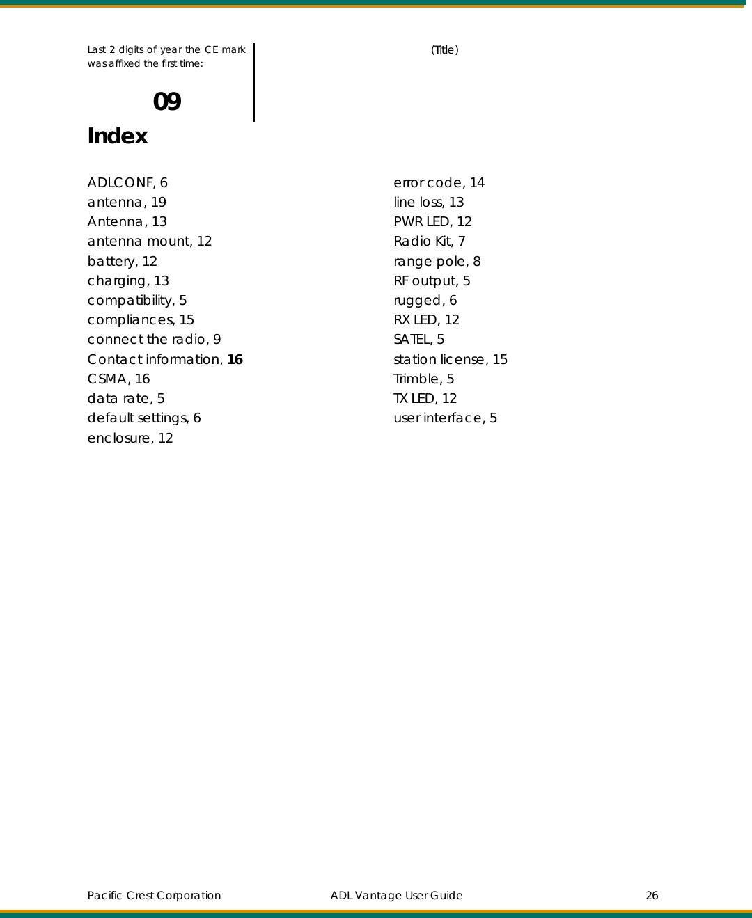
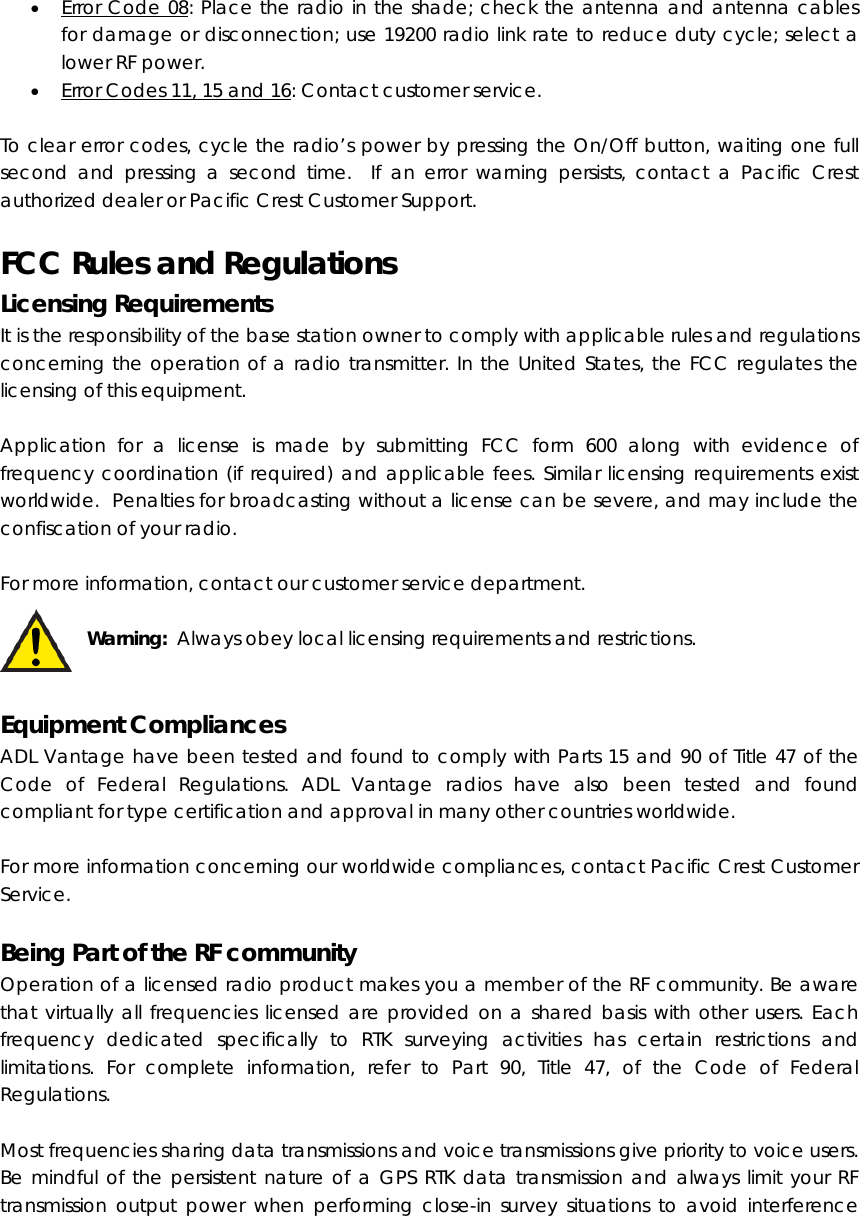
![Corporation and its authorized dealers can provide you with everything you need including a tripod accessory kit and a battery/charger kit. Antenna and Antenna Mount If you have an antenna with a male TNC connector, you can attach it directly to the RF connector on the top of the ADL Vantage. We highly recommend, however, that you elevate your RF antenna as much as possible. The most common set up is similar to that seen in Figure 1 where an antenna cable with male TNC connector is attached to the ADL Vantage. The other end of this cable is attached to a tripod or elevated section of range pole. The RF antenna is then attached to the end of the cable. Pacific Crest offers an antenna cable that attaches to standard 5/8-inch threaded tripods and range poles and antennas with NMO connectors. We recommend inspecting the antenna center push-pin contact to make sure that it makes good contact with the antenna mount. A good antenna connection is critical to system performance. Although transmitting without an antenna will not cause damage to the ADL Vantage, it is not recommended. Using a gained antenna will raise the Effective Radiated Power of the ADL Vantage radio. Make sure the resultant Effective Radiated Power does not exceed your licensed limit. Figure 1 - ADL Vantage Setup Tripod Side Clip Before connecting any cables, screw the ADL Vantage’s tripod clip (PN F01003) onto the back of the radio and insert the clip into the slot on a tripod. Comment [CB1]: Should show the antenna cable running from the top of the radio up to the bottom of the antenna.](https://usermanual.wiki/Trimble-Navigation/ADLV/User-Guide-1157631-Page-9.png)
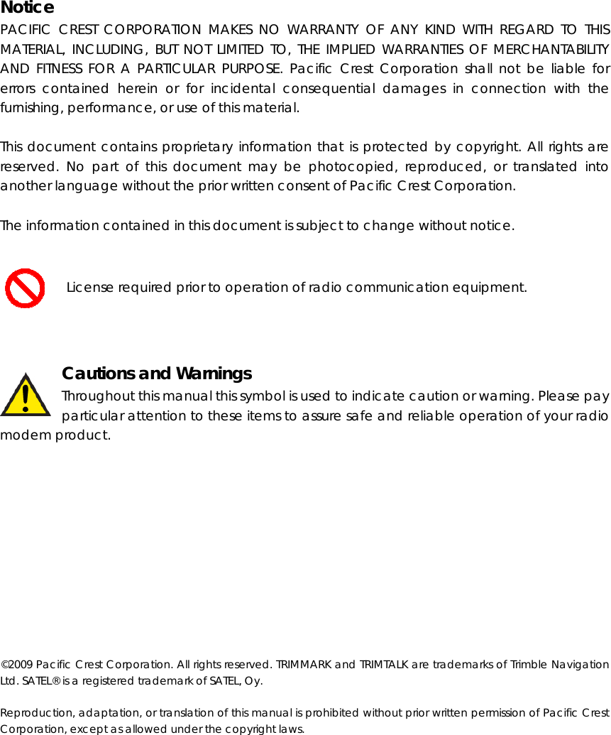
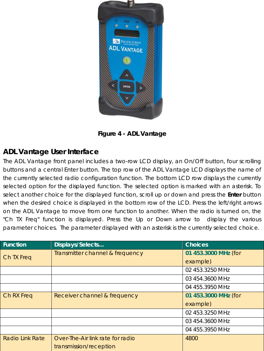
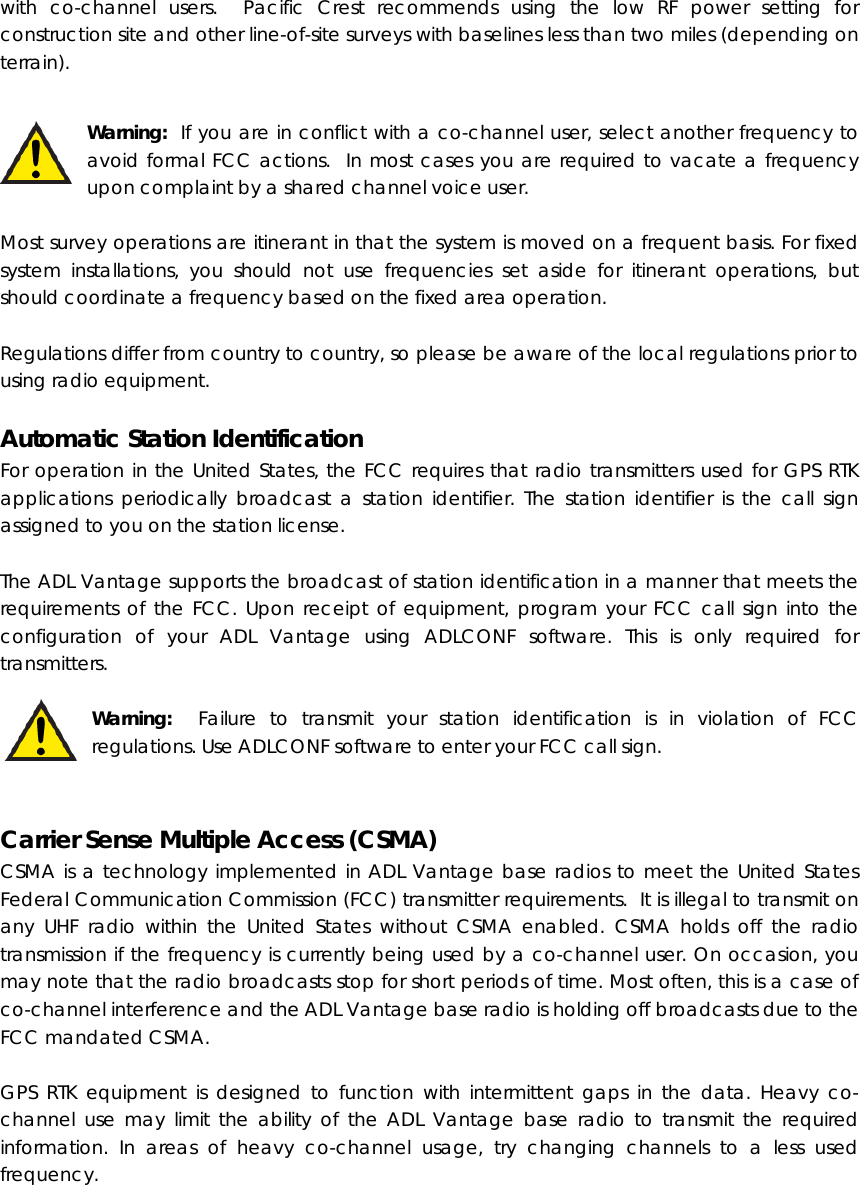
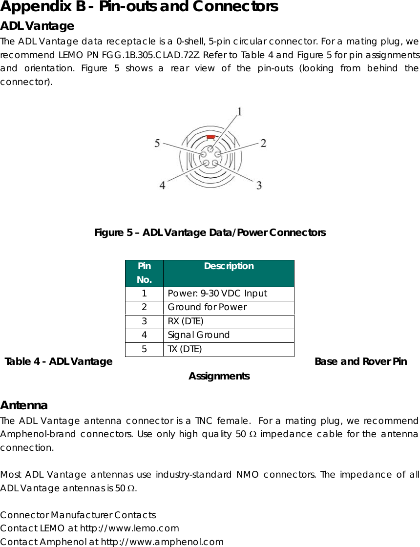
![Figure 2 - ADL Vantage Tripod Clip Data/Power Cable The ADL Vantage is connected to a data source, such as a GNSS receiver, using a data/power cable (see Figure 3). This cable is available with different connectors for attaching to a large variety of data sources. Contact your Pacific Crest sales representative for selecting the best cable to meet your needs. Figure 3 - ADL Vantage Data/Power Cable Each ADL Vantage data/power cable also connects the radio (and in some cases the data source) to external power via an SAE-type connector. Pacific Crest strongly recommends you use the ADL Vantage battery (PN A02663), which includes an SAE connector. This is sold both separately and as part of the ADL Vantage Battery/Charger Kit (PN K01115). Operating the ADL Vantage Turning on ADL Vantage To turn on the ADL Vantage, either attach the programming cable to the radio and to wall/mains current or attach the data/power cable to the radio and the battery. Then press the On/Off button in the center of the front panel seen in Figure 4. Comment [CB2]: Change “GPS Connector” to “Data Source Connector”](https://usermanual.wiki/Trimble-Navigation/ADLV/User-Guide-1157631-Page-10.png)
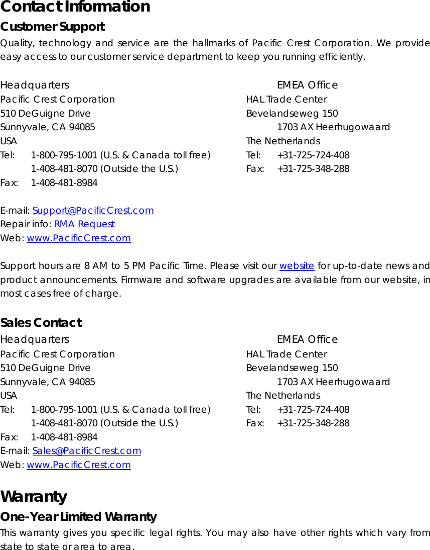
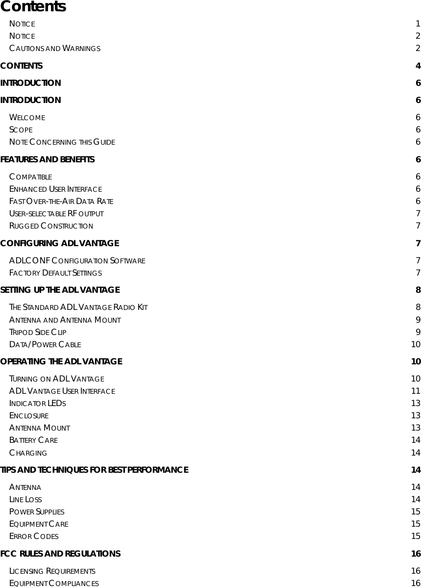
![Pacific Crest Corporation ADL Vantage User Guide 25 Appendix E – Document of Conformity EC Type Declaration of Conformity We, Pacific Crest Corporation 510 DeGuigne Sunnyvale, California 94085 U.S.A. declare under our sole responsibility that the product: ADL Vantage consisting of the following models: XXXX 390 – 430 MHz XXXX 450 – 470 MHz following the provisions of the Directives (if applicable): R&TTE Directive 1999/5/EC EMC Directive 2004/108/EC LVD Directive 2006/95/EC and Standards to which Conformity is Declared: EMC Requirements: EN 300 113-2 V1.4.1 (2007-07) EN 301 489-1 V1.8.1 (2008-04) EN 301 489-5 V1.3.1 (2002-08) Safety Requirements: EN 60950-1:2001 + A11:2004 Place: Sunnyvale, California Date of Issue: May 27, 2009 Signature John F. Cameron (Name) This Declaration of Conformity is suitable to the European Standard EN 45014 General Criteria for Supplier's Declaration of Conformity. The basis for the criteria has been found in international documentation, particularly in ISO/IEC, Guide 22, 1982, Information on manufacturer's Declaration of Conformity with standards or other technical specifications. This declaration is an EC Type Declaration of Conformity as referenced in Annex IV of EC directive 2004/108/EC, The EMC Directive and as in Annex III of EC directive 2006/95/EC The Low Voltage Directive General Manager Comment [CB3]: Input correct Comment [CB4]: Input correct Comment [CB5]: We obviously need to change this](https://usermanual.wiki/Trimble-Navigation/ADLV/User-Guide-1157631-Page-25.png)