Trimble Navigation ADLV Advanced Data Link Vantage and Advanced Data Link Sentry (ADLV) User Manual
Trimble Navigation Ltd Advanced Data Link Vantage and Advanced Data Link Sentry (ADLV) Users Manual
Users Manual

ADL Vantage
User's Guide
August 2009
P/N: M00815
Pacific Crest Corporation
510 DeGuigne Drive
Sunnyvale, CA 94085
(408) 481-8070
(408) 481-8984 Fax
info@PacificCrest.com
www.PacificCrest.com

Notice
PACIFIC CREST CORPORATION MAKES NO WARRANTY OF ANY KIND WITH REGARD TO THIS
MATERIAL, INCLUDING, BUT NOT LIMITED TO, THE IMPLIED WARRANTIES OF MERCHANTABILITY
AND FITNESS FOR A PARTICULAR PURPOSE. Pacific Crest Corporation shall not be liable for
errors contained herein or for incidental consequential damages in connection with the
furnishing, performance, or use of this material.
This document contains proprietary information that is protected by copyright. All rights are
reserved. No part of this document may be photocopied, reproduced, or translated into
another language without the prior written consent of Pacific Crest Corporation.
The information contained in this document is subject to change without notice.
License required prior to operation of radio communication equipment.
Cautions and Warnings
Throughout this manual this symbol is used to indicate caution or warning. Please pay
particular attention to these items to assure safe and reliable operation of your radio
modem product.
©2009 Pacific Crest Corporation. All rights reserved. TRIMMARK and TRIMTALK are trademarks of Trimble Navigation
Ltd. SATEL® is a registered trademark of SATEL, Oy.
Reproduction, adaptation, or translation of this manual is prohibited without prior written permission of Pacific Crest
Corporation, except as allowed under the copyright laws.
Contents
NOTICE 1
NOTICE 2
CAUTIONS AND WARNINGS 2
CONTENTS 4
INTRODUCTION 6
INTRODUCTION 6
WELCOME 6
SCOPE 6
NOTE CONCERNING THIS GUIDE 6
FEATURES AND BENEFITS 6
COMPATIBLE 6
ENHANCED USER INTERFACE 6
FAST OVER-THE-AIR DATA RATE 6
USER-SELECTABLE RF OUTPUT 7
RUGGED CONSTRUCTION 7
CONFIGURING ADL VANTAGE 7
ADLCONF CONFIGURATION SOFTWARE 7
FACTORY DEFAULT SETTINGS 7
SETTING UP THE ADL VANTAGE 8
THE STANDARD ADL VANTAGE RADIO KIT 8
ANTENNA AND ANTENNA MOUNT 9
TRIPOD SIDE CLIP 9
DATA/POWER CABLE 10
OPERATING THE ADL VANTAGE 10
TURNING ON ADL VANTAGE 10
ADL VANTAGE USER INTERFACE 11
INDICATOR LEDS 13
ENCLOSURE 13
ANTENNA MOUNT 13
BATTERY CARE 14
CHARGING 14
TIPS AND TECHNIQUES FOR BEST PERFORMANCE 14
ANTENNA 14
LINE LOSS 14
POWER SUPPLIES 15
EQUIPMENT CARE 15
ERROR CODES 15
FCC RULES AND REGULATIONS 16
LICENSING REQUIREMENTS 16
EQUIPMENT COMPLIANCES 16
BEING PART OF THE RF COMMUNITY 16
AUTOMATIC STATION IDENTIFICATION 17
CARRIER SENSE MULTIPLE ACCESS (CSMA) 17
CONTACT INFORMATION 18
CUSTOMER SUPPORT 18
SALES CONTACT 18
WARRANTY 18
ONE-YEAR LIMITED WARRANTY 18
EXCLUSIONS 19
WARRANTY LIMITATIONS 19
APPENDIX A - SAFETY INFORMATION 20
EXPOSURE TO RADIO FREQUENCY ENERGY 20
APPENDIX B - PIN-OUTS AND CONNECTORS 21
ADL VANTAGE 21
ANTENNA 21
APPENDIX C - TECHNICAL SPECIFICATIONS 23
APPENDIX D – SOFTWARE 24
SOFTWARE COMPATIBILITY 24
APPENDIX E – DOCUMENT OF CONFORMITY 25
INDEX 26
Figures
Figure 1 - ADL Vantage Setup......................................................................................................................................9
Figure 2 - ADL Vantage GPS Cable...........................................................................................................................10
Figure 3 - ADL Vantage................................................................................................................................................11
Figure 4 – ADL Vantage Data/Power Connectors.................................................................................................21
TABLES
Table 1 - ADL Vantage Factory Defaults....................................................................................................................8
Table 2 – ADL Vantage User Interface Display........................................................................................................13
Table 3 - ADL Vantage Error Codes ..........................................................................................................................15
Table 4 - ADL Vantage Base and Rover Pin Assignments.....................................................................................21
Introduction
Welcome
Thank you for purchasing the Advanced Data Link (ADL) Vantage for use with your survey
system. The ADL Vantage™ is an advanced, high speed, wireless data link that is designed
specifically for GNSS/RTK applications. Your success in using the ADL Vantage is Pacific Crest
Corporation’s primary goal. Pacific Crest stands behind the ADL Vantage by providing expert
support and service. Your comments and questions are welcome.
Scope
This guide provides information concerning the use of the ADL Vantage. This guide is written for
the first-time user and gives details concerning system setup, operation and maintenance. We
urge you to take the time to review this short manual completely prior to setting up your
system.
Note Concerning this Guide
We believe that the ADL Vantage system provides the best value and performance for the
user. As such, we provide our equipment in complete turnkey systems, including all of the items
necessary for operation with your GPS.
You may have purchased your ADL Vantage from a third party. On occasion, the bundled
product provided by these sources may differ from the kits provided directly from Pacific Crest
Corporation. If this guide does not accurately reflect the equipment that you received, please
contact your supplier for specific instructions concerning the setup of items that differ.
Features and Benefits
Compatible
Facilitates GNSS equipment mix and match
• Interoperable with Pacific Crest RFM and PDL, SATEL, and Trimble radio products
• All models support both 12.5 and 25 kHz channel bandwidth communications
• 40 MHz-wide channel tables (390-430 and 430-470 MHz models)
• Provides upgrade path for existing installations
Enhanced User Interface
Backlit LCD display and five-button navigation interface
• View and change radio channel, modulation and protocol types
• Monitor signal levels, baud rates, and other parameters
Fast Over-the-Air Data Rate
19,200 bits per second
• Reduced latency provides better GPS position information
• Lower power consumption allows longer field operation

User-selectable RF output
Select between 0.1. 0.5, 1, 2 and 4 Watts
• Increase range by switching to 2 or 4 Watts (where permitted)
• Increase battery life by reducing output power when you don’t need the range
Rugged Construction
Designed specifically for real-world working environments
• All metal construction and shock mounted electronics ensure highest reliability and EMI-
resistance
• Watertight operation stands up to bad weather conditions
Configuring ADL Vantage
ADLCONF Configuration Software
ADLCONF is a suite of software utilities for configuring and troubleshooting Pacific Crest’s
Advanced Data Link (ADL) line of digital communication radios and modems. Running
ADLCONF on a PC attached via serial cable to an ADL radio allows you to check the status of
the radio, input channel tables, and set radio parameters such as channel bandwidth and
output power.
ADLCONF software is found on the ADL Vantage system CD. The latest version is available for
free download from www.PacificCrest.com. A user guide that completely describes how to
configure the ADL Vantage radio is available by running ADLCONF and clicking Help > User
Guide. The ADLCONF User’s Guide is also available on the Pacific Crest website.
Factory Default Settings
You can return your ADL Vantage radio to its factory default configuration using ADLCONF
software. Simply click the Restore Factory button to the right of the screen and then the
Program button. The factory default settings are as follows:
Radio Link Rate 9600
Modulation Type GMSK
Sensitivity Low (Base)
Transmit Power (there is no default)
Scramble Control On
CSMA On
Forward Error Correction Yes
Transmit Retries 10
TX ACK Timeout 10
Modem Address 0
Destination Address 255
RX Delay 0
TX Delay 2
RX LED Meaning Signal received

Call Sign: CALL SIGN
Owner: (there is no default)
Low Voltage Turn Warning 10 V
Low Voltage Turn Off 9 V
Turn Off LCD Backlight No
Turn Off LCD Delay After 20 seconds
Serial Interface
PC Baud Rate: 38400
Parity: None
Soft Break Disabled: Yes
Protocol Mode: Transparent with EOT Timeout
EOT Timeout: 50
EOT Character: (not used)
Security Code: 00000000
Table 1 - ADL Vantage Factory Defaults
Setting Up the ADL Vantage
The Standard ADL Vantage Radio Kit
The Standard ADL Vantage Radio Kit consists of the following:
• ADL Vantage radio
• Wall/mains power supply
• Wall plug with adaptor set
• Programming cable
• ADL Vantage CD containing:
o ADL Vantage User's Guide
o ADLCONF User's Guide
o ADLCONF Software
o PCC Range Estimator
To configure the radio with ADLCONF software,
• Connect the power supply to the main wall current
• Connect the programming cable to:
o The power supply
o The ADL Vantage radio
o Your PC
• Turn on the radio
• Launch ADLCONF software and refer to the section of the ADLCONF User’s Guide on
connecting the program to your radio.
To operate your ADL Vantage radio in the field you will need an antenna, a portable power
supply and a cable to connect to a data source such as a GNSS receiver. Pacific Crest
Corporation and its authorized dealers can provide you with everything you need including a
tripod accessory kit and a battery/charger kit.
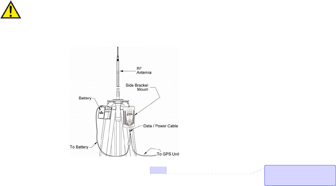
Antenna and Antenna Mount
If you have an antenna with a male TNC connector, you can attach it directly to the RF
connector on the top of the ADL Vantage. We highly recommend, however, that you elevate
your RF antenna as much as possible. The most common set up is similar to that seen in Figure
1 where an antenna cable with male TNC connector is attached to the ADL Vantage. The
other end of this cable is attached to a tripod or elevated section of range pole. The RF
antenna is then attached to the end of the cable. Pacific Crest offers an antenna cable that
attaches to standard 5/8-inch threaded tripods and range poles and antennas with NMO
connectors.
We recommend inspecting the antenna center push-pin contact to make sure that it makes
good contact with the antenna mount. A good antenna connection is critical to system
performance.
Although transmitting without an antenna will not cause damage to the ADL
Vantage, it is not recommended. Using a gained antenna will raise the Effective
Radiated Power of the ADL Vantage radio. Make sure the resultant Effective
Radiated Power does not exceed your licensed limit.
Figure 1 - ADL Vantage Setup
Tripod Side Clip
Before connecting any cables, screw the ADL Vantage’s tripod clip (PN F01003) onto the back
of the radio and insert the clip into the slot on a tripod.
Comment [CB1]: Should show the
antenna cable running from the top of
the radio up to the bottom of the
antenna.
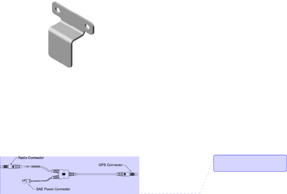
Figure 2 - ADL Vantage Tripod Clip
Data/Power Cable
The ADL Vantage is connected to a data source, such as a GNSS receiver, using a
data/power cable (see Figure 3). This cable is available with different connectors for attaching
to a large variety of data sources. Contact your Pacific Crest sales representative for selecting
the best cable to meet your needs.
Figure 3 - ADL Vantage Data/Power Cable
Each ADL Vantage data/power cable also connects the radio (and in some cases the data
source) to external power via an SAE-type connector. Pacific Crest strongly recommends you
use the ADL Vantage battery (PN A02663), which includes an SAE connector. This is sold both
separately and as part of the ADL Vantage Battery/Charger Kit (PN K01115).
Operating the ADL Vantage
Turning on ADL Vantage
To turn on the ADL Vantage, either attach the programming cable to the radio and to
wall/mains current or attach the data/power cable to the radio and the battery. Then press
the On/Off button in the center of the front panel seen in Figure 4.
Comment [CB2]: Change “GPS
Connector” to “Data Source
Connector”
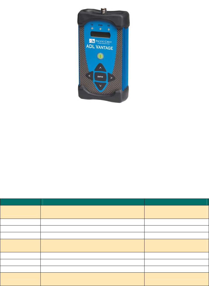
Figure 4 - ADL Vantage
ADL Vantage User Interface
The ADL Vantage front panel includes a two-row LCD display, an On/Off button, four scrolling
buttons and a central Enter button. The top row of the ADL Vantage LCD displays the name of
the currently selected radio configuration function. The bottom LCD row displays the currently
selected option for the displayed function. The selected option is marked with an asterisk. To
select another choice for the displayed function, scroll up or down and press the Enter button
when the desired choice is displayed in the bottom row of the LCD. Press the left/right arrows
on the ADL Vantage to move from one function to another. When the radio is turned on, the
"Ch TX Freq" function is displayed. Press the Up or Down arrow to display the various
parameter choices. The parameter displayed with an asterisk is the currently selected choice.
Function Displays/Selects… Choices
Ch TX Freq Transmitter channel & frequency 01 453.3000 MHz (for
example)
02 453.3250 MHz
03 454.3600 MHz
04 455.3950 MHz
Ch RX Freq Receiver channel & frequency 01 453.3000 MHz (for
example)
02 453.3250 MHz
03 454.3600 MHz
04 455.3950 MHz
Radio Link Rate Over-The-Air link rate for radio
transmission/reception 4800

9600
19200
8000
16000
Serial Baud Serial baud rate of the radio’s data port 2400
4800
9600
19200
38000
115200
Modulation Data modulation type GMSK
4LFSK
Data Protocol Data protocol type PCC EOT (End of
Transmission)
PCC EOC (End of
Character)
Packet Switched
TRIMMARK™II/IIe
TRIMTALK™
TT450S (HW)
TRIMMARK 3
SATEL®
Repeater Mode Sets the radio to be a repeater No
Yes
If a Trimble protocol is
selected:
No
Base + 1 Repeater
Base + 2 Repeaters
Repeater 1
Repeater 2
Sensitivity Radio squelch level Low (Base)
Moderate
High (Rover)
Transmit Power Transmitter power level 0.1 Watts
0.5 Watts
1 Watt (where permitted)
2 Watts (where permitted)
4 Watts (where permitted)
CSMA Carrier Sense Multiple Access On
Off
RX LED Meaning What it means when the RX LED flashes Signal Received
Data Received

Signal Strength Strength of the received signal (RSSI) RSSI value displayed in dBm
Device Status Radio identification information Battery status
Serial number
Owner name
Call sign
Channel bandwidth (BW)
TX status
FW version
Error Code Error code and brief description No Error
01: Voltage High
02: Voltage Low
08: Temp High
11: Memory Error
15: Tx Frequency Not
Locked
16: Rx Frequency Not
Locked
Table 2 – ADL Vantage User Interface Display
Indicator LEDs
The TX LED indicates that the ADL Vantage is broadcasting. In most GPS RTK applications, the
TX LED will flash approximately one time per second.
The PWR LED indicates the power status and also provides a low external voltage supply
indicator. When lit, power is turned on. The PWR LED will blink to indicate if the external voltage
supply is approaching the minimum value. If the PWR LED does not respond to the On/Off
button, then the level of the external voltage supply should be inspected.
The RX LED indicates that the ADL Vantage is receiving an RF carrier signal from another radio
or from another source of interference. During normal operation, the RX LED will flash at a
once-per-second rate indicating the reception of transmissions from the transmitting radio. If
the RX LED is on continuously, then a source of interference may be impacting the ability of
the ADL Vantage to receive data. Try repositioning the antenna, or changing to another
channel at both the transmitter and receiver to reduce or eliminate the interference.
Enclosure
The ADL Vantage enclosure is a tough, impact- and scratch-resistant, aluminum. Elastomer
end caps provide the first level of shock protection for the internal components. An additional
isolation system inside the enclosure reduces vibration impact to the sensitive radio receiver
board.
Antenna Mount
The integrated antenna mount provides an industry standard TNC-female RF connector that is
compatible with a wide range of mobile whip antennas.
Battery Care
The ADL Vantage Battery/Charger kit (PN K01115) includes a 12-Volt, 8-AHr, deep-discharge,
lead-acid battery. This battery provides all-day operation for the radio and may be recharged
approximately 300 times over a period of 3 years.
To power the ADL Vantage with a user-supplied battery, select a deep-discharge battery with
a minimum capacity of 8 AHr. Batteries designed for automotive use can be used if necessary
but will be damaged by repetitive discharge/charge cycles and are therefore not
recommended.
Charging
The charger supplied with the ADL Vantage Battery/Charger kit (PN K01115) provides two-
stage charging and should be connected to the battery following every full day of operation
to assure good battery life and performance. The first stage quickly charges the battery to
capacity and the second stage trickle charges the battery to maintain a full charge.
It is important to periodically charge any battery that is stored for an extended length of time.
Storing batteries for an extended time in a discharged state will damage them. To recharge a
user-supplied battery, select a charger of appropriate type.
Tips and Techniques for Best Performance
Antenna
Antenna placement is critical for good performance. Range and coverage is directly
proportional to the height of the transmitting and receiving antennas in addition to antenna
gain. Where possible, select a reference station location that takes advantage of terrain to
get the transmitting antenna as high as possible.
Always use the telescoping antenna mast and raise the antenna as high as is practical and
safe given terrain and wind conditions.
Do not use a gained antenna if doing so increases the radio’s Effective Radiated Power
beyond the limit of your license.
Line Loss
Line loss, produced by RF or antenna cables that connect the radio and antenna, decreases
the output power (Wattage) transmitted by the antenna, thereby decreasing the signal’s
range. To minimize line loss, please check the loss-per-length of cable to be used. For every

3dB of line loss, the output power (Wattage) will decrease by half. For example, if you had a
35W radio and had a line loss of 3dB in your cable, the output power would be 17.5W, thereby
reducing the range of the radio’s signal. Every 6 db of loss will reduce the radio’s effective
range by 50%.
Power Supplies
Maintain batteries in a fully charged state. The ADL Vantage batteries will last longer if they are
not allowed to become completely discharged. We recommend routinely connecting the
battery to its charger after every working day and for 24 hours every 3 months during period of
non-use. This will assure optimal performance and long battery life.
Equipment Care
Routine equipment care will prolong the life and reliability of your ADL family products. Radio
communication equipment is susceptible to damage from shock or environmental extremes.
Never operate the ADL Vantage outside the operating specifications contained in Appendix
C.
Error Codes
The ADL Vantage performs a variety of power-up and run-time tests to assure optimal
operation. Tests include environmental as well as electrical measurements designed to avoid
damage to the unit while maintaining adequate operation. In the event of an error condition,
an error code is displayed on the LCD screen and the Power LED flashes the number of the
error code (two flashes for Error Code 02, followed by a pause, two more flashes, etc.). Table 3
lists the possible error conditions.
Code Description
01 Input voltage is too high
02 Input voltage is too low
08 Internal temperature exceeds limit for
operation
E11 Memory error
E15 TX Frequency Lock Error
E16 RX Frequency Lock Error
Table 3 - ADL Vantage Error Codes
What to do
• Error Code 01-02: Check battery or power supply voltage level; check power cables;
recharge or replace the battery; check the charger.

• Error Code 08: Place the radio in the shade; check the antenna and antenna cables
for damage or disconnection; use 19200 radio link rate to reduce duty cycle; select a
lower RF power.
• Error Codes 11, 15 and 16: Contact customer service.
To clear error codes, cycle the radio’s power by pressing the On/Off button, waiting one full
second and pressing a second time. If an error warning persists, contact a Pacific Crest
authorized dealer or Pacific Crest Customer Support.
FCC Rules and Regulations
Licensing Requirements
It is the responsibility of the base station owner to comply with applicable rules and regulations
concerning the operation of a radio transmitter. In the United States, the FCC regulates the
licensing of this equipment.
Application for a license is made by submitting FCC form 600 along with evidence of
frequency coordination (if required) and applicable fees. Similar licensing requirements exist
worldwide. Penalties for broadcasting without a license can be severe, and may include the
confiscation of your radio.
For more information, contact our customer service department.
Warning: Always obey local licensing requirements and restrictions.
Equipment Compliances
ADL Vantage have been tested and found to comply with Parts 15 and 90 of Title 47 of the
Code of Federal Regulations. ADL Vantage radios have also been tested and found
compliant for type certification and approval in many other countries worldwide.
For more information concerning our worldwide compliances, contact Pacific Crest Customer
Service.
Being Part of the RF community
Operation of a licensed radio product makes you a member of the RF community. Be aware
that virtually all frequencies licensed are provided on a shared basis with other users. Each
frequency dedicated specifically to RTK surveying activities has certain restrictions and
limitations. For complete information, refer to Part 90, Title 47, of the Code of Federal
Regulations.
Most frequencies sharing data transmissions and voice transmissions give priority to voice users.
Be mindful of the persistent nature of a GPS RTK data transmission and always limit your RF
transmission output power when performing close-in survey situations to avoid interference

with co-channel users. Pacific Crest recommends using the low RF power setting for
construction site and other line-of-site surveys with baselines less than two miles (depending on
terrain).
Warning: If you are in conflict with a co-channel user, select another frequency to
avoid formal FCC actions. In most cases you are required to vacate a frequency
upon complaint by a shared channel voice user.
Most survey operations are itinerant in that the system is moved on a frequent basis. For fixed
system installations, you should not use frequencies set aside for itinerant operations, but
should coordinate a frequency based on the fixed area operation.
Regulations differ from country to country, so please be aware of the local regulations prior to
using radio equipment.
Automatic Station Identification
For operation in the United States, the FCC requires that radio transmitters used for GPS RTK
applications periodically broadcast a station identifier. The station identifier is the call sign
assigned to you on the station license.
The ADL Vantage supports the broadcast of station identification in a manner that meets the
requirements of the FCC. Upon receipt of equipment, program your FCC call sign into the
configuration of your ADL Vantage using ADLCONF software. This is only required for
transmitters.
Warning: Failure to transmit your station identification is in violation of FCC
regulations. Use ADLCONF software to enter your FCC call sign.
Carrier Sense Multiple Access (CSMA)
CSMA is a technology implemented in ADL Vantage base radios to meet the United States
Federal Communication Commission (FCC) transmitter requirements. It is illegal to transmit on
any UHF radio within the United States without CSMA enabled. CSMA holds off the radio
transmission if the frequency is currently being used by a co-channel user. On occasion, you
may note that the radio broadcasts stop for short periods of time. Most often, this is a case of
co-channel interference and the ADL Vantage base radio is holding off broadcasts due to the
FCC mandated CSMA.
GPS RTK equipment is designed to function with intermittent gaps in the data. Heavy co-
channel use may limit the ability of the ADL Vantage base radio to transmit the required
information. In areas of heavy co-channel usage, try changing channels to a less used
frequency.

Contact Information
Customer Support
Quality, technology and service are the hallmarks of Pacific Crest Corporation. We provide
easy access to our customer service department to keep you running efficiently.
Headquarters EMEA Office
Pacific Crest Corporation HAL Trade Center
510 DeGuigne Drive Bevelandseweg 150
Sunnyvale, CA 94085 1703 AX Heerhugowaard
USA The Netherlands
Tel: 1-800-795-1001 (U.S. & Canada toll free) Tel: +31-725-724-408
1-408-481-8070 (Outside the U.S.) Fax: +31-725-348-288
Fax: 1-408-481-8984
E-mail: Support@PacificCrest.com
Repair info: RMA Request
Web: www.PacificCrest.com
Support hours are 8 AM to 5 PM Pacific Time. Please visit our website for up-to-date news and
product announcements. Firmware and software upgrades are available from our website, in
most cases free of charge.
Sales Contact
Headquarters EMEA Office
Pacific Crest Corporation HAL Trade Center
510 DeGuigne Drive Bevelandseweg 150
Sunnyvale, CA 94085 1703 AX Heerhugowaard
USA The Netherlands
Tel: 1-800-795-1001 (U.S. & Canada toll free) Tel: +31-725-724-408
1-408-481-8070 (Outside the U.S.) Fax: +31-725-348-288
Fax: 1-408-481-8984
E-mail: Sales@PacificCrest.com
Web: www.PacificCrest.com
Warranty
One-Year Limited Warranty
This warranty gives you specific legal rights. You may also have other rights which vary from
state to state or area to area.
Pacific Crest Corporation warrants ADL family products, inclusive of cables and batteries,
against defects in materials and workmanship for a period of one year from receipt by the
end-user.
Exclusions
Should Pacific Crest Corporation be unable to repair or replace the product within a
reasonable amount of time, a refund of the purchase price may be given upon return of the
product.
The warranty on your ADL Vantage shall not apply to defects resulting from:
• Improper or inadequate maintenance by the customer
• Unauthorized modification, negligence or misuse
• Operation outside of the environment specifications
Warranty Limitations
This warranty set forth above is exclusive and no other warranty, whether written or oral, is
expressed or implied. Pacific Crest Corporation specifically disclaims the implied warranties of
merchantability and fitness for a particular purpose.

Appendix A - Safety Information
Exposure to Radio Frequency Energy
The ADL Vantage is designed to comply with the following national and international
standards and guidelines regarding exposure of human beings to radio frequency
electromagnetic energy, in addition to protection against harmful interference of neighboring
electrical equipment:
• FCC Report and Order FCC 96-326 (August, 1996)
• American National Standards Institute (C95.3-1992)
• National Council on Radiation Protection and Measurement (NCRP - 1986)
• International Commission on Non-ionizing Radiation Protection (ICNRP - 1986)
• European Committee for Electrotechnical Standardization (CENELEC)
• FCC CFR47 Part 15
• FCC CFR47 Part 90
• Industry Canada RSS 119
• ETSI EN 300 113-2
• ETSI EN 300 489
• ACA AS/NZS 4295
• iDA Spec 111
• OFTA STD-1E
• SRRC CMII
Contact your sales representative for model specific country approval.
To assure optimal radio performance and to ensure that exposure to RF energy is within the
guidelines in the above standards, the following operating procedures should be observed:
• Do not operate a transceiver when someone is within the distance noted below of the
antenna (unity gain).
o 120 cm (approx. 4 feet) for ADL Vantage @ 4 Watts
o 30 cm (approx. 12 inches) for ADL Vantage @ 2 Watts
o 15 cm (approx. 6 inches) for ADL Vantage @ ½ Watt
• Do not operate the transceiver unless all RF connectors are secure and any open
connectors are properly terminated.
• Avoid contact with the antenna while operating the transceiver.
• Do not operate the transceiver with a damaged antenna. If a damaged antenna
comes in contact with the skin, a minor burn may result.
• Do not operate the equipment near electrical blasting caps or in an explosive
atmosphere.
Warning: Changes or modifications not expressly approved by the FCC could void
the user’s authority to operate the equipment.
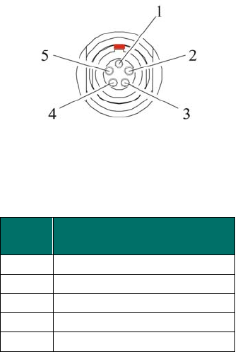
Appendix B - Pin-outs and Connectors
ADL Vantage
The ADL Vantage data receptacle is a 0-shell, 5-pin circular connector. For a mating plug, we
recommend LEMO PN FGG.1B.305.CLAD.72Z. Refer to Table 4 and Figure 5 for pin assignments
and orientation. Figure 5 shows a rear view of the pin-outs (looking from behind the
connector).
Figure 5 – ADL Vantage Data/Power Connectors
Table 4 - ADL Vantage Base and Rover Pin
Assignments
Antenna
The ADL Vantage antenna connector is a TNC female. For a mating plug, we recommend
Amphenol-brand connectors. Use only high quality 50 Ω impedance cable for the antenna
connection.
Most ADL Vantage antennas use industry-standard NMO connectors. The impedance of all
ADL Vantage antennas is 50 Ω.
Connector Manufacturer Contacts
Contact LEMO at http://www.lemo.com
Contact Amphenol at http://www.amphenol.com
Pin
No. Description
1 Power: 9-30 VDC Input
2 Ground for Power
3 RX (DTE)
4 Signal Ground
5 TX (DTE)
Appendix C - Technical Specifications
General Specifications
Communication
1 RS-232 port, 115.2 kbps maximum
User Interface
Refer to Pin-Outs below
Power
External
9.0 – 30.0 VDC
During RX 0.6 Watts nominal @ 12.0 VDC
During TX 7 Watts nominal @ 12.0 VDC, 1W RF output
13.4 Watts nominal @ 12.0 VDC, 4W RF output
Modem Specifications
Link Rate/Modulation
19,200 bps/4FSK
9600 bps/4FSK
19,200 bps/GMSK
16,000 bps/GMSK
9600 bps/GMSK
8000 bps/GMSK
4800 bps/GMSK
Link Protocols Transparent EOT/EOC, Packet-switched, TRIMMARK™ ,
TRIMTALK™, TT450S (HW), SATEL®
Forward Error Correction Yes
Radio Specifications
Frequency Bands
390-430, 430-470 MHz
Frequency Control Synthesized 12.5 kHz tuning resolution
Frequency stability +/- 1 PPM
RF Transmitter Output Programmable to 0.1 – 4 Watts (where permitted)
Sensitivity -110 dBm BER 10
-5
Type Certification All models are type accepted and certified for
operation in the U.S., Europe, Australia, New Zealand,
Russia and Canada
Environmental Specifications
Operating Temperature (Receiver) -40˚ to +85˚ C (-40˚ to +185˚ F)
Operating Temperature (Transmitter) -40˚ to +65˚ C (-40˚ to +149˚ F)
Storage Temperature (Receiver/Transmitter) -55˚ to +85˚ C (-67˚ to +185˚ F)
Vibration Spec: MIL-STD-810F
Mechanical Specifications
Dimensions 3.5” L x 1.809” W x 6.3” H
(8.89 cm L x 4.6 cm W x 16.0 cm H)
Weight 567 grams (20 oz.)

Pacific Crest Corporation ADL Vantage User Guide 24
Data/Power Connector 5-pin, #1-shell LEMO
RF Connector 50 Ohm, TNC-female
Appendix D – Software
Software Compatibility
Current versions of the following software were tested and verified for compatibility with
Windows XP and the Microsoft Business Edition of the Windows Vista operating systems:
• ADLCONF
• PCC Range Estimator
Pacific Crest Corporation ADL Vantage User Guide 25
Appendix E – Document of Conformity
EC Type Declaration of Conformity
We, Pacific Crest Corporation
510 DeGuigne
Sunnyvale, California 94085
U.S.A.
declare under our sole responsibility that the product:
ADL Vantage
consisting of the following models:
XXXX 390 – 430 MHz
XXXX 450 – 470 MHz
following the provisions of the Directives (if applicable):
R&TTE Directive 1999/5/EC
EMC Directive 2004/108/EC
LVD Directive 2006/95/EC
and Standards to which Conformity is Declared:
EMC Requirements:
EN 300 113-2 V1.4.1 (2007-07)
EN 301 489-1 V1.8.1 (2008-04)
EN 301 489-5 V1.3.1 (2002-08)
Safety Requirements:
EN 60950-1:2001 + A11:2004
Place: Sunnyvale, California Date of Issue: May 27, 2009
Signature
John F. Cameron
(Name)
This Declaration of
Conformity is suitable to the
European Standard EN 45014
General Criteria for Supplier's
Declaration of Conformity.
The basis for the criteria has
been found in international
documentation, particularly
in ISO/IEC, Guide 22, 1982,
Information on
manufacturer's Declaration
of Conformity with standards
or other technical
specifications.
This declaration is an EC Type
Declaration of Conformity as
referenced in Annex IV of EC
directive 2004/108/EC, The
EMC Directive and as in
Annex III of EC directive
2006/95/EC The Low Voltage
Directive
General Manager
Comment [CB3]: Input correct
Comment [CB4]: Input correct
Comment [CB5]: We obviously
need to change this

Pacific Crest Corporation ADL Vantage User Guide 26
Last 2 digits of year the CE mark
was affixed the first time:
09
(Title)
Index
ADLCONF, 6
antenna, 19
Antenna, 13
antenna mount, 12
battery, 12
charging, 13
compatibility, 5
compliances, 15
connect the radio, 9
Contact information, 16
CSMA, 16
data rate, 5
default settings, 6
enclosure, 12
error code, 14
line loss, 13
PWR LED, 12
Radio Kit, 7
range pole, 8
RF output, 5
rugged, 6
RX LED, 12
SATEL, 5
station license, 15
Trimble, 5
TX LED, 12
user interface, 5

Pacific Crest Corporation ADL Vantage User Guide 27
510 DeGuigne Drive • • Sunnyvale, CA 94085

Pacific Crest Corporation ADL Vantage User Guide 28
M00815