Trimble Navigation XDLM UHF Transceiver Module User Manual TDL 450i Integrator s Guide 03 2012 indd

Trimble Navigation Ltd UHF Transceiver Module TDL 450i Integrator s Guide 03 2012 indd

Contents

Users Manual Part One
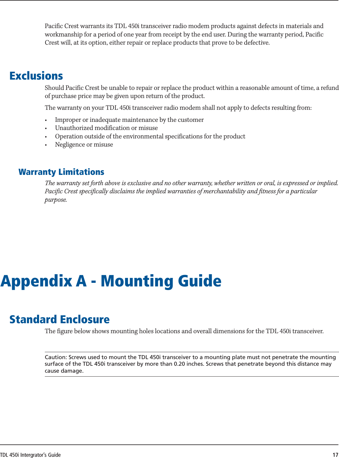
INTEGRATOR'S GUIDETrimble® TDL 450i
AMERICAS & ASIA-PACIFICTrimble Navigation Ltd.Integrated Technologies510 DeGuigne DriveSunnyvale, CA 94085USA+1-408-481-8070 Phone+1-408-481-8984 FaxEUROPE & MIDDLE EASTTrimble Navigation Ltd.Integrated TechnologiesHAL Trade CenterBevelandseweg 1501703 AX HeerhugowaardNetherlands+31-725-724-408 Phone+31-725-348-288 FaxRUSSIATrimble Navigation Ltd.Integrated TechnologiesTel: +7 495 5041081Email: rusales-pc@trimble.comCHINATrimble Navigation Ltd.Integrated Technologies311 Fute (M) Road, 3/FWai Gaoqiao Free Trade ZonePudong, Shanghai 200131ChinaEmail:  chinasales-pc@trimble.com
TDL 450i Intergrator’s Guide 3Contact InformationSupport hours are 8 am to 5 pm Paci c Time. Please visit our website for up-to-date news and product announcements. Firmware and software upgrades are available from our website, usually free of charge. Legal notices©2012, Trimble Navigation Limited. All rights reserved. SATEL is a registered trademark of SATEL Oy. Trimble is a trademark of Trimble Navigation Limited, registered in the United States and in other countries. TRIMMARK and TRIMTALK are trademarks of Trimble Navigation Limited. Microsoft, Windows, and Windows Vista are either registered trademarks or trademarks of Microsoft Corporation in the United States and/or other countries. All trademarks are the property of their respective owners. WarrantyOne-Year limited warranty  is warranty gives you speci c legal rights. You may also have other rights which vary from state to state or area to area.Trimble warrants TDL family products, inclusive of cables and batteries, against defects in materials and workmanship for a period of one year from receipt by the end-user.ExclusionsShould Trimble be unable to repair or replace the product within a reasonable amount of time, a refund of the purchase price may be given upon return of the product.  e warranty on your radio shall not apply to defects resulting from:•  Improper or inadequate maintenance by the customer• Unauthorized modi cation, negligence, or misuse•  Operation outside of the environment speci cationsWarranty limitations  is warranty set forth above is exclusive and no other warranty, whether written or oral, is expressed or implied. Trimble speci cally disclaims the implied warranties of merchantability and  tness for a particular purpose.NoticesClass B Statement – Notice to Users.   is equipment has been tested and found to comply with the limits for a Class B digital device, pursuant to Part 15 of the FCC rules.   ese limits are designed to provide reasonable protection against harmful interference in a residential installation.   is equipment generates, uses, and can radiate radio frequency energy and, if not installed and used in accordance with the instructions, may cause harmful interference to radio communication. However, there is no guarantee that interference will not occur in a particular installation. If this equipment does cause harmful interference to radio or television reception, which can be determined by turning the equipment o   and on, the user is encouraged to try to correct the interference by one or more of the following measures:•  Reorient or relocate the receiving antenna.•  Increase the separation between the equipment and the receiver.•  Connect the equipment into an outlet on a circuit di erent from that to which the receiver is connected.•  Consult the dealer or Trimble directly for help.Changes and modi  cations not expressly approved by the manufacturer or registrant of this equipment can void your authority to operate this equipment under Federal Communications Commission rules.Canada  is digital apparatus does not exceed the Class B limits for radio noise emissions from digital apparatus as set out in the radio interference regulations of the Canadian Department of Communications.Le présent appareil numérique n’émet pas de bruits radioélectriques dépassant les limites applicables aux appareils numériques de Classe B prescrites dans le règlement sur le brouillage radioélectrique édicté par le ministère des Communications du Canada.Europe  is product has been tested and found to comply with the requirements for a Class B device pursuant to European Council Directive 1999/5/EC on R&TTE, thereby satisfying the requirements for CE Marking and sale within the European Economic Area (EEA).   ese requirements are designed to provide reasonable protection against harmful interference when the equipment is operated in a residential or commercial environment, and to ensure that the equipment is safe.Australia and New Zealand  is product conforms with the regulatory requirements of the Australian Communications and Media Authority (ACMA) EMC framework, thus satisfying the requirements for C-Tick Marking and sale within Australia and New Zealand. Notice to Our European Union CustomersFor product recycling instructions and more information, please go to www.trimble.com/ev.shtml. Recycling in Europe: To recycle Trimble WEEE (Waste Electrical and Electronic Equipment, products that run on electrical power.), Call +31 497 53 24 30, and ask for the “WEEE Associate”. Or, mail a request for recycling instructions to:Trimble Europe BVc/o Menlo Worldwide LogisticsMeerheide 455521 DZ Eersel, NLTrimble Navigation LimitedIntegrated Technologies510 DeGuigne DriveSunnyvale, CA 94085USA1-408-481-8070 Phone1-800-795-1001 (USA toll free)1-408-481-8982 Faxwww.trimble.com
TDL 450i Intergrator’s Guide 4Safety InformationBefore you use your radio, ensure that you have read and understood this publication, as well as safety requirements.CAUTION – A license is required before operating radio communication equipment.Warnings and cautionsAn absence of specific alerts does not mean that there are no safety risks involved.Always follow the instructions that accompany a Warning or Caution. The information they provide is intended to minimize the risk of personal injury and/or damage to the equipment. In particular, observe safety instructions that are presented in the following formats:WARNING – A Warning alerts you to a likely risk of serious injury to your person and/or damage to the equipment. A warning identifies the nature of the risk and the extent of possible injury and/or damage. It also describes how to protect yourself and/or the equipment from this risk. Warnings that appear in the text are repeated at the front of the manual.CAUTION – A Caution alerts you to a possible risk of damage to the equipment and/or loss of data. A Caution describes how to protect the equipment and/or data from thisExposure to radio frequency energyThe radio is designed to comply with the following national and international standards and guidelines regarding exposure of human beings to radio frequency electromagnetic energy, in addition to protection against harmful interference of neighboring electrical equipment:•  FCC Report and Order FCC 96-326 (August, 1996)•  American National Standards Institute (C95.3-1992)•  National Council on Radiation Protection and Measurement (NCRP - 1986)•  International Commission on Non-ionizing Radiation Protection (ICNRP - 1986)•  European Committee for Electrotechnical Standardization (CENELEC)•  FCC CFR47 Part 15•  FCC CFR47 Part 90•  Industry Canada RSS 119•  ETSI EN 300 113-2•  ETSI EN 300 489•  ACA AS/NZS 4295•  iDA Spec 111• OFTA STD-1E• RRC CMIIContact your sales representative for model specific country approval.To assure optimal radio performance and to ensure that exposure to RF energy is within the guidelines in the above standards, observe the following operating procedures:•  Do not operate a transceiver when someone is within the distance noted below of the antenna (unity gain). –45 cm (approximately 12 in) for the TDL 450i/
TDL 450i Intergrator’s Guide 5 –15 cm (approximately 6 in) for the TDL 450i radio @ 1 W•  Do not operate the transceiver unless all RF connectors are secure and any open connectors are properly terminated.•  Avoid contact with the antenna while operating the transceiver.•  Do not operate the transceiver with a damaged antenna. If a damaged antenna comes in contact with the skin, a minor burn may result.•  Do not operate the equipment near electrical blasting caps or in an explosive atmosphere.CAUTION – Changes or modifications not expressly approved by the FCC could void the user’s authority to operate the equipment.FCC Rules and RegulationsLicensing requirementsIt is the responsibility of the owner to comply with applicable rules and regulations concerning the operation of a radio transmitter. In the United States, the FCC regulates the licensing of this equipment.Application for a license is made by submitting FCC Form 600 along with evidence of frequency coordination (if required) and applicable fees. Similar licensing requirements exist worldwide. Penalties for broadcasting without a license can be severe, and may include the confiscation of your radio.For more information, contact our customer service department. WARNING – Always obey local licensing requirements and restrictions. It is illegal to transmit in the United States while CSMA is turned off. CSMA is not required within the European Union and should be turned off.Equipment compliancesThe radios have been tested and found to comply with Parts 15 and 90 of Title 47 of the Code of Federal Regulations. They have also been tested and found compliant for type certification and approval in many other countries worldwide.For more information concerning our worldwide compliances, contact customer support.Being part of the RF communityOperation of a licensed radio product makes you a member of the RF community. Be aware that virtually all frequencies licensed are provided on a shared basis with other users. Each frequency dedicated specifically to RTK surveying activities has certain restrictions and limitations. For complete information, refer to the appropriate documentation from the licensing agency in your country of operation, e.g., Part 90, Title 47, of the Code of Federal Regulations.Most frequencies sharing data transmissions and voice transmissions give priority to voice users. Be mindful of the persistent nature of a GPS RTK data transmission and always limit your RF transmission output power when performing close-in survey situations to avoid interference with co-channel users. Trimble recommends using the low RF power setting for construction site and other line-of-site surveys with baselines less than two miles (depending on terrain).WARNING – If you are in conflict with a co-channel user, select another frequency to avoid formal actions by government agencies. In most cases, you are required to vacate a frequency upon complaint by a shared channel voice user.Most survey operations are itinerant in that the system is moved on a frequent basis. For fixed system
TDL 450i Intergrator’s Guide 6installations, you should not use frequencies set aside for itinerant operations, but should coordinate a frequency based on the fixed area operation.Regulations differ from country to country, please be aware of the local regulations before using radio equipment.Automatic station identificationFor operation in the United States, the FCC requires that radio transmitters broadcast a station identifier every 15 minutes. The station identifier is the call sign assigned to you on the station license.The radios support the broadcast of station identification in a manner that meets the requirements of the FCC. Upon receipt of equipment, use the XDLCONF software to program your FCC call sign into the configuration of the radio. This is only required for transmitters.The call sign is transmitted every 15 minutes in Morse code. It is not included in any data packet and so is not processed by the receiving radio. However, data transmission is interrupted for a few seconds while the call sign is being transmitted. If you leave the Call sign field blank (on the XDLCONF Identification screen), the radio programmed with this configuration file will not transmit any call sign.WARNING – Failure to transmit your station identification is in violation of FCC regulations. If you are operating outside the United States, check with the local authorities if you need to transmit a call sign.Carrier Sense Multiple Access (CSMA)CSMA is a technology implemented in the radios to meet the United States Federal Communication Commission (FCC) transmitter requirements. It is illegal to transmit on any UHF radio within the United States without CSMA enabled. CSMA holds off the radio transmission if the frequency is currently being used by a co-channel user. On occasion, you may note that the radio broadcasts stop for short periods of time. Most often, this is a case of co-channel interference and the radio is holding off broadcasts due to the FCC-mandated CSMA.Note – You should turn CSMA off when transmitting within the European Union.GPS RTK equipment is designed to function with intermittent gaps in the data. Heavy co-channel use may limit the ability of the radio to transmit the required information. In areas of heavy co-channel usage, try changing channels to a less used frequency.
TDL 450i Intergrator’s Guide 7ContentsSafety Information . . . . . . . . . . . . . . . . . . . . . . . . . . . . . . . . . . . . . . . . . . . . . . . . . . . . . . 4Introduction  . . . . . . . . . . . . . . . . . . . . . . . . . . . . . . . . . . . . . . . . . . . . . . . . . . . . . . . . . . . 8Getting Started. . . . . . . . . . . . . . . . . . . . . . . . . . . . . . . . . . . . . . . . . . . . . . . . . . . . . . . . . 8Interface Port Pin Out . . . . . . . . . . . . . . . . . . . . . . . . . . . . . . . . . . . . . . . . . . . . . . . . . . . . . . . . . . . . . . . . . . . . . . . . . 9TX and RX Pins. . . . . . . . . . . . . . . . . . . . . . . . . . . . . . . . . . . . . . . . . . . . . . . . . . . . . . . . . . . . . . . . . . . . . . . . . . . 10Antenna Port   . . . . . . . . . . . . . . . . . . . . . . . . . . . . . . . . . . . . . . . . . . . . . . . . . . . . . . . . . . . . . . . . . . . . . . . . . . . . 11Compliance   . . . . . . . . . . . . . . . . . . . . . . . . . . . . . . . . . . . . . . . . . . . . . . . . . . . . . . . . . . . . . . . . . . . . . . . . . . . . . . . . . 11Compatibility . . . . . . . . . . . . . . . . . . . . . . . . . . . . . . . . . . . . . . . . . . . . . . . . . . . . . . . . . . . . . . . . . . . . . . . . . . . . . . . . 11Protocols and Modes of Operation   . . . . . . . . . . . . . . . . . . . . . . . . . . . . . . . . . . . . . . . 11Electrical Considerations . . . . . . . . . . . . . . . . . . . . . . . . . . . . . . . . . . . . . . . . . . . . . . . . 13Power Supply  . . . . . . . . . . . . . . . . . . . . . . . . . . . . . . . . . . . . . . . . . . . . . . . . . . . . . . . . . . . . . . . . . . . . . . . . . . . . . . . . 13CMOS Input/Output Protection Circuitry   . . . . . . . . . . . . . . . . . . . . . . . . . . . . . . . . . . . . . . . . . . . . . . . . 13Error Codes . . . . . . . . . . . . . . . . . . . . . . . . . . . . . . . . . . . . . . . . . . . . . . . . . . . . . . . . . . . . . . . . . . . . . . . . . . . . . . . . . . 14Shielding Considerations   . . . . . . . . . . . . . . . . . . . . . . . . . . . . . . . . . . . . . . . . . . . . . . . . . . . . . . . . . . . . . . . . . . . . 14Frequency Planning . . . . . . . . . . . . . . . . . . . . . . . . . . . . . . . . . . . . . . . . . . . . . . . . . . . . . . . . . . . . . . . . . . . . . . . . . . 14Mechanical Considerations . . . . . . . . . . . . . . . . . . . . . . . . . . . . . . . . . . . . . . . . . . . . . . 15EMI interferers  . . . . . . . . . . . . . . . . . . . . . . . . . . . . . . . . . . . . . . . . . . . . . . . . . . . . . . . . . . . . . . . . . . . . . . . . . . . . . . 15Shock and Vibration. . . . . . . . . . . . . . . . . . . . . . . . . . . . . . . . . . . . . . . . . . . . . . . . . . . . . . . . . . . . . . . . . . . . . . . . . . 15  ermal Transfer. . . . . . . . . . . . . . . . . . . . . . . . . . . . . . . . . . . . . . . . . . . . . . . . . . . . . . . . . . . . . . . . . . . . . . . . . . . . . 15Materials  . . . . . . . . . . . . . . . . . . . . . . . . . . . . . . . . . . . . . . . . . . . . . . . . . . . . . . . . . . . . . . . . . . . . . . . . . . . . . . . . . . . . 16Service and Support   . . . . . . . . . . . . . . . . . . . . . . . . . . . . . . . . . . . . . . . . . . . . . . . . . . . 16Philosophy   . . . . . . . . . . . . . . . . . . . . . . . . . . . . . . . . . . . . . . . . . . . . . . . . . . . . . . . . . . . . . . . . . . . . . . . . . . . . . . . . . . 16Phone/Internet Support  . . . . . . . . . . . . . . . . . . . . . . . . . . . . . . . . . . . . . . . . . . . . . . . . . . . . . . . . . . . . . . . . . . . . . 16Warranty   . . . . . . . . . . . . . . . . . . . . . . . . . . . . . . . . . . . . . . . . . . . . . . . . . . . . . . . . . . . . 16One-Year Limited Warranty  . . . . . . . . . . . . . . . . . . . . . . . . . . . . . . . . . . . . . . . . . . . . . . . . . . . . . . . . . . . . . . . . . . 16Exclusions . . . . . . . . . . . . . . . . . . . . . . . . . . . . . . . . . . . . . . . . . . . . . . . . . . . . . . . . . . . . . . . . . . . . . . . . . . . . . . . . . . . 17Warranty Limitations   . . . . . . . . . . . . . . . . . . . . . . . . . . . . . . . . . . . . . . . . . . . . . . . . . . . . . . . . . . . . . . . . . . . . 17Appendix A - Mounting Guide  . . . . . . . . . . . . . . . . . . . . . . . . . . . . . . . . . . . . . . . . . . . 17Standard Enclosure  . . . . . . . . . . . . . . . . . . . . . . . . . . . . . . . . . . . . . . . . . . . . . . . . . . . . . . . . . . . . . . . . . . . . . . . . . . 17Appendix B - Cables and Connectors  . . . . . . . . . . . . . . . . . . . . . . . . . . . . . . . . . . . . . . 19Value-Added Cable Products . . . . . . . . . . . . . . . . . . . . . . . . . . . . . . . . . . . . . . . . . . . . . . . . . . . . . . . . . . . . . . . . . 19Interface Connector . . . . . . . . . . . . . . . . . . . . . . . . . . . . . . . . . . . . . . . . . . . . . . . . . . . . . . . . . . . . . . . . . . . . . . . . . . 19RF Connector  . . . . . . . . . . . . . . . . . . . . . . . . . . . . . . . . . . . . . . . . . . . . . . . . . . . . . . . . . . . . . . . . . . . . . . . . . . . . . . . . 19Appendix C - Technical Specifi cations . . . . . . . . . . . . . . . . . . . . . . . . . . . . . . . . . . . . . . 20Appendix D – API Commands . . . . . . . . . . . . . . . . . . . . . . . . . . . . . . . . . . . . . . . . . . . . 21
TDL 450i Intergrator’s Guide 8IntroductionThis guide provides information concerning the integration of the TDL 450i radio modem transceiver into your product (Model Numbers XDLM-0, XDLM-1 and XDLM-2). This guide should be used in conjunction with the XDLCONF User’s Guide – Dealer Version that should be referenced for general information concerning the configuration of TDL 450i modems, and also for detailed programming information. The TDL 450i is a general-purpose radio modem transceiver that is compatible with TRIMMARK radios, the Advanced Data Link (ADL) and the Positioning Data Link (PDL) product families of radio modems. The TDL 450i transceiver is designed specifically for integration into existing or new products. Its small size, light weight and power efficient operation provide superior performance in embedded systems. Getting StartedCaution:  TDL 450i transceiver must be handled with care during installation. Remove the transceiver from its protective bag only in an ESD safe area. To set up the hardware components, follow these steps:  1.  Plug the TDL 450i transceiver into an I/O-test board’s 20-pin connector  2.  Attach an antenna cable to the TDL 450i transceiver  3.  Attach a PC interface cable to a 9-pin UART connector on the I/O-test board  4.  Attach the PC interface cable to a serial port on your PC  5.  Attach a wall cable to the AC/DC adapter and select the proper plug from the adapter kit  6.  Attach the AD/DC adapter’s tubular plug to the power jack on the I/O-test board  7.  Plug in an XDLCONF or  XDLCONF (Dealer’s Version) USB key on your PC  8.  Download and install the latest Sentinel driver for the USB key from http://www.safenet-inc.  com/support/tech/latestdriver.asp  9.  Launch XDLCONF  and refer to its user guide for instructions on connecting to the TDL 450i   transceiver
TDL 450i Intergrator’s Guide 9 TDL 450i in Test BoardInterface Port Pin OutThe standard TDL 450i transceiver comprises a 30-pin port for power, data and interfacing with other electronic devices. 30 Pin TDL 450i BoardThe following signals are available on the 30-pin connector: Pin Name Description1 GND GROUND FOR SIGNAL AND POWER2 DO NOT USE FACTORY USE ONLY,  NO CONNECTION3 TX TX DATA, DTE SERIAL PORT, 3V CMOS  (3.3V COMPATIBLE)4 DO NOT USE FACTORY USE ONLY, PLEASE NO CONNECTION5 GND GROUND FOR SIGNAL AND POWER6 DO NOT USE FACTORY  USE  ONLY,  PLEASE  LEAVE  NO  CONNECTION
TDL 450i Intergrator’s Guide 10Pin Name Description7 GND GROUND FOR SIGNAL AND POWER8 DO NOT USE FACTORY  USE  ONLY,  PLEASE  LEAVE  NO  CONNECTION9 GND GROUND FOR SIGNAL AND POWER10 DO NOT USE FACTORY  USE  ONLY,  PLEASE  LEAVE  NO  CONNECTION11 CONFIG  I/O TO FORCE RADIO SWITCH BETWEEN OPERATING MODE AND CONFIGURATION MODE12 DO NOT USE FACTORY  USE  ONLY,  PLEASE  LEAVE  NO  CONNECTION13 DO NOT USE FACTORY  USE  ONLY,  PLEASE  LEAVE  NO  CONNECTION14 RX RX DATA, DTE SERIAL PORT, 3V CMOS  (3.3V COMPATIBLE)15 DO NOT USE FACTORY  USE  ONLY,  PLEASE  LEAVE  NO  CONNECTION16 DO NOT USE FACTORY  USE  ONLY,  PLEASE  LEAVE  NO  CONNECTION17 DO NOT USE FACTORY  USE  ONLY,  PLEASE  LEAVE  NO  CONNECTION18 VCC POWER IN19 GND GROUND FOR SIGNAL AND POWER20 GND GROUND FOR SIGNAL AND POWER21 GND GROUND FOR SIGNAL AND POWER22 GND GROUND FOR SIGNAL AND POWER23 VCC POWER IN24 VCC POWER IN25 VCC POWER IN26 VCC POWER IN27 VCC POWER IN28 VCC POWER IN29 POWER POWER DOWN RADIO30 GND GROUND FOR SIGNAL AND POWERTX and RX PinsPin 3 is used by the TDL 450i module to received data from an external device (a PC, GPS receiver, weather sensor, etc). Pin 14 is used to transmit data to the external device.  The external device is transmitting data to the TDL 450i on Pin 3, so according to the DTE naming convention, Pin 3 is called the “TX Data” pin.  The external device receives data from the TDL 450i’s Pin 14 so this is called the “RX Data” pin.Pin Orientation
TDL 450i Intergrator’s Guide 11Antenna Port A coaxial antenna port is provided for connecting the antenna system to the TDL 450i transceiver. The antenna connector is a 50-Ohm MMCX type. Appendix B provides part numbers and manufacturer information for compatible interface and RF connectors. Pacific Crest also provides custom manufactured cables designed to your specific needs. Contact us for a quotation for your specific cabling requirements.    Warning: Don’t transmit without first connecting an antenna. Compliance The TDL 450i transceiver radio modem is designed to be compliant with worldwide regulatory requirements, including FCC part 90, ETS 300-113-2, IC RSS 119 and others. Warning: The TDL 450i transceiver is classified as an intentional radiator of type radio transceiver.  Conducted and radiated emissions of the standard TDL 450i transceiver do not exceed the requirements of FCC part 90 and ETS 300-113-2.  OEM is responsible for full compliance of final product.Compatibility The TDL 450i transceiver is compatible with most modes of operation supported by the TDL, ADL and PDL product families of radio modems.  See the Protocols and Modes of Operation section for an overview of the protocols and modes that are supported with the TDL 450i transceiver radio modem. The compatibility also extends to XDLCONF software configuration program and the ADL Test application that are supplied as part of the TDL 450i Developer’s Kit.Protocols and Modes of Operation The TDL 450i transceiver radio modem is completely configurable using XDLCONF software. Configuration parameters define the DTE interface and the over-the-air protocol.  Depending on the application you may need to change the factory default settings.  The following table shows the factory default configuration of the TDL 450i transceiver. Parameter DefaultChannel 1Baud Rate 38400Parity NoneSoft Break Disable OffTX Power 0.5 WMode Transparent EOT Timeout
TDL 450i Intergrator’s Guide 12Parameter DefaultLink Rate 9600 bps GMSKEOT 50 msRepeater Delay 0 CSMA On*FEC OnScrambling OnSensitivity High Local Address 0Destination Address 255*CSMA is required to be on only inside the United States.  You should turn CSMA off in EU countries.TDL 450i Factory Default SettingsUp to 32 frequencies are stored in the configuration memory called the channel table. The selection of channel is subject to proper licensing of the corresponding frequencies by the appropriate governmental agency. Please refer to the XDLCONF User’s Guide for instructions in creating and uploading channel tables into the TDL 450i transceiver modem. The  TDL 450i  transceiver  modem  supports  multiple  protocols  and  modes  of  operation including:• •  Transparent with EOT Timeout•  Transparent with EOT Character• TRIMTALK™ 450S• TRIMTALK II/IIE•  TT450S  (HW)• TRIMMARK™ 3• SATEL®• Transparent FSTRefer to the XDLCONF User’s Guide for a detailed description.
TDL 450i Intergrator’s Guide 13Electrical Considerations Power Supply The TDL 450i transceiver has a power supply connection on Pin 18 and Pins 23 to 28 of the interface connector. Pins 1, 5,7, 9,30 and Pins 19 to 22 are connections to both power ground and serial interface signal grounds.  Note that these pins are tied to a common point on the TDL 450i transceiver.  If there is a potential for a ground path current loop due to improper power application, we recommend a fusible link be inserted in the signal ground to protect the TDL 450i transceiver. TDL 450i transceiver modems are designed to operate with unregulated DC voltage levels between 3.6 and 4VDC. The power supply must be capable of sourcing 2A.Data Interface TDL 450i transceiver provides one data port, which has a simple 3-wire CMOS electrical interface with signals for transmitting data to and receiving data from the TDL 450i transceiver, and for providing a reference ground for the TX (Pin 3) and RX (Pin 14) signals. Note:  We define TX and RX as a DTE port. In other words, an external device transmits data to the radio modem’s TX pin (Pin 3) and receives data from the radio modem’s RX pin (Pin 14).CMOS Input/Output Protection Circuitry The TX signal terminates into a CMOS input port on the TDL 450i transceiver and should be driven externally or pulled to ground through a 10 kΩ resistor. The absolute maximum voltage applied to the TX signal is -0.3 V to 3.3 V. The signals are CMOS outputs. Note that loading the RX signals increases the power consumption of the TDL 450i transceiver and these should be limited to no more than 2.5 mA each to maintain performance across the temperature range. Caution: Internal circuitry protects the inputs and outputs against damage caused by high static voltages or electric fields; however, normal precautions are necessary to avoid application of any voltage higher than the maximum-rated voltages.
TDL 450i Intergrator’s Guide 14Error CodesThe TDL 450i transceiver performs a variety of power-up and run-time tests to assure optimal operation. Tests include environmental as well as electrical measurements designed to avoid damage to the unit while maintaining adequate operation. A 50Ω impedance coaxial MMCX style RF connector is provided for attachment to an external antenna system.  The MMCX connector offers a positive friction locking mechanism that is very reliable. In some circumstances, it may be required to provide a physical stop to prevent the MMCX plug from becoming disconnected due to extreme shock or vibration. The TDL 450i transceiver requires an antenna and feed cable system that is impedance- matched to 50Ω. We recommend that high quality RG-178 or equivalent coaxial cable be used for internal wiring of the RF signal from the MMCX to the panel connector.  We also suggest the selection of an antenna that has a low VSWR (less than 1.5:1) and that has been tuned for operation in the band of the TDL 450i transceiver. Caution: Improper impedance matching of the antenna, connectors or cable will degrade the performance of the TDL 450i transceiver. Shielding Considerations The TDL 450i transceiver is designed to operate in proximity to noise generating circuitry.  However, certain radiated or conducted frequencies may degrade the performance of the TDL 450i transceiver or render it inoperable. When possible, provide well-grounded shielding between circuits that radiate, such as power supplies, voltage-controlled oscillators, crystal oscillators and the TDL 450i transceiver. Frequency Planning The TDL 450i transceiver contains a very sensitive, dual-conversion super-heterodyne receiver.Caution: Radiated and conducted signals to and from the TDL 450i transceiver may cause problems due to interference.  Proper attention to frequency planning may reduce interference from radiated or conducted frequencies that fall within the pass-bands of the filters at the IF frequencies. We recommend the use of upfront analysis of the product frequency plan (including harmonics) and then the use of a spectrum analyzer to determine the potential for interference within the pass-bands of the various front-end and band pass filters. The following table indicates the frequencies and band pass filter characteristics that are areas of potential interference.Circuit Center Frequency (MHz) Bandwidth (MHz)RF front-end  438 70
TDL 450i Intergrator’s Guide 15Circuit Center Frequency (MHz) Bandwidth (MHz)First IF 54.45  0.015 Second IF  0.450  0.010 TDL 450i Frequency PlanMechanical Considerations EMI interferers The TDL 450i transceiver is easily mounted inside new and existing products. The TDL 450i transceiver is specifically designed for operation in harsh environments. For best performance, mount the radio away from potential EMI radiators and route RF signals apart from digital signals. Caution: We do not recommend the bundling of the antenna interface cable with other signal cables internal to your product. Shock and VibrationSensitive radio transceivers, such as the TDL 450i transceiver, are susceptible to interference due to mechanical shock and vibration. To reduce the potential for electromechanical interference, a robust mounting scheme must be used when being integrated into other systems. A thin damping pad between the mounting surface and the TDL 450i transceiver may be required. We recommend the use of damping pads made of PORON(R) or a similar material. Thermal TransferThe TDL 450i transceiver requires additional thermal heat dissipation in order to supply maximum power out at elevated ambient temperatures and high duty cycles.  The TDL 450i transceiver has a thermal sensor and a firmware controlled limit switch. The TDL 450i will shut down when the PCB temperature reaches 85°C to prevent permanent damage to transmitter.  The integrated heat sink is adequate for most bench top testing but when the TDL 450i transceiver is integrated into other systems additional thermal heat sinking must be considered.   The TDL 450I will produce
TDL 450i Intergrator’s Guide 16approximately 6 Watts of heat at full RF power out. Refer to Appendix A for mounting diagrams and specification. Materials The TDL 450i transceiver is housed in a metal shield that is a conductor and is electrically connected to the ground and signal ground pins. Service and Support Philosophy Pacific Crest is dedicated to providing the very best service and support possible. We recognize that the success of our business is directly related to the success our customers have in using our products. For this reason, we provide easy access with our toll free number, which we encourage our customers to use if they are experiencing difficulties or problems with the products we supply. Let us know what you think. A cornerstone of our business philosophy is to evolve our product lines to match the needs of our customers. Your input allows us to better determine what we need to do to keep our product and support offerings in alignment with your needs. Phone/Internet Support Phone support is available during our business hours, Monday through Friday (7 a.m. to 4 p.m. Pacific Standard Time). Call 1-800-795-1001 (U.S. and Canada), +1-408-481-8070 (International), +1-408-481-8984 (Fax). You can contact the support group via our web site, www.PacificCrest.com or send an e-mail to support@pacificcrest.comWarranty One-Year Limited Warranty This warranty gives you specific legal rights. You may also have other rights which vary from state to state or province to province.
TDL 450i Intergrator’s Guide 17Pacific Crest warrants its TDL 450i transceiver radio modem products against defects in materials and workmanship for a period of one year from receipt by the end user. During the warranty period, Pacific Crest will, at its option, either repair or replace products that prove to be defective. Exclusions Should Pacific Crest be unable to repair or replace the product within a reasonable amount of time, a refund of purchase price may be given upon return of the product.  The warranty on your TDL 450i transceiver radio modem shall not apply to defects resulting from: •   Improper or inadequate maintenance by the customer •   Unauthorized modification or misuse •   Operation outside of the environmental specifications for the product •   Negligence or misuse Warranty Limitations The warranty set forth above is exclusive and no other warranty, whether written or oral, is expressed or implied. Pacific Crest specifically disclaims the implied warranties of merchantability and fitness for a particular purpose. Appendix A - Mounting Guide Standard Enclosure The figure below shows mounting holes locations and overall dimensions for the TDL 450i transceiver. Caution: Screws used to mount the TDL 450i transceiver to a mounting plate must not penetrate the mounting surface of the TDL 450i transceiver by more than 0.20 inches. Screws that penetrate beyond this distance may cause damage.
TDL 450i Intergrator’s Guide 18[21.34].840[9.91].390[46.61]1.835[69.85]2.750[15.57].613[1.27].050[39.50]1.555[23.37].920[3.56].140[44.65]1.758RF CONNECTORRIGHT ANGLE MMCX[8.05].317[54.66]21.52[8.74].344 [2.39].094[1.63].064TEST FIXTURE TOOLING HOLEDO NOT USE FOR MOUNTINGTEST FIXTURE TOOLING HOLEDO NOT USE FOR MOUNTING[3.18]4x 0.125KEEPOUT AREA BOTH SIDESCOMPONENTS AND TEST POINTSLOCATED HERE.100 INCH MINIMUM CLEARANCETDL 450i Mounting Template
TDL 450i Intergrator’s Guide 19RF CONNECTORRIGHT SIDE MMCXFARSIDEDATA CONNECTOR AVXTDL 450i Mounting Template with ShieldsAppendix B - Cables and ConnectorsValue-Added Cable ProductsPacific Crest manufactures a wide variety of high-quality custom cables in support of its OEM customers.  Contact your Pacific Crest sales representative to discuss your custom cable requirements.Interface ConnectorThe 30-pin data/power header is a Samtec TFM series housing a standard-configuration connector, AVX part number 14-5046-030-630-829. The mating Samtec connector is part number 24-5046-030-600-829 for a board-to-board interface See AVX website: http://www.samtec.com and www.AVXcorp.com for other mating connector options.RF Connector
TDL 450i Intergrator’s Guide 20The RF connector is compatible with an MMCX-style coaxial plug. Plugs are available from many sources and in many configurations. We use plugs manufactured by Radiall. Radiall MMCX right-angle plug for use with RG-178 cable is part number R110 172 100.  Radiall MMCX straight plug for use with RG-178 cable is part number R110 083 120.Appendix C - Technical SpecificationsGeneralDTE - DCE interfaceUser InterfaceCMOS, 115.2 kbps maximumLow Profile 30 Pin Connector, Refer to Pin-Outs Power requirementsExternal 3.6 VDC ± 0.05mVDuring Rx 0.45 W nominal @ 3.6 VDCDuring Tx 6.5 W nominal @ 3.6 VDC, 2 W RF outputRadioFrequency band 403-473 MHzFrequency control Synthesized 12.5 kHz tuning resolutionFrequency stability +/- 1PPMChannel spacing Channel spacing 12.5/25 kHz (user-selectable)RF transmitter output 0.5, 1.0 or 2 Watt (Programmable)Sensitivity -110 dBm BER = 1 x 10⁻⁵Adjacent channel selectivity>50dBType certification All models will be type accepted and certified for operation in the U.S., Europe, Australia, New Zealand, and CanadaFCC, IC, EU, NZ, Australia ETS300-113-2ModemLink Rate/Modulation 4-Level FSK: 9600, 19,200 bpsGMSK: 4800, 8000, 9600, 16,000, 19,200 bpsLink Protocols Transparent EOT/EOC/FST, SATEL, TRIMTALK II/IIe, TRIMMARK3, TRIMTALK 450SForward Error Correction (FEC) and DetectionYesEnvironmentalShock and vibration Per MIL-STD-810FAmbient temperature rangeOperating temperature (receiver)-40 ˚C to +85 ˚C  (-40 ˚F to +185 ˚F)Operating temperature (transmitter)-40 ˚C to +65 ˚C  (-22 ˚F to +149 ˚F)Storage temperature -55 ˚C to +85 ˚C  (-67 ˚F to +185 ˚F)MechanicalDimensions 69.8 mm L x 46.6 mm W x 11.2 mm H2.750” L x 1.835” W x 0.442” HWeight 1.4 oz (40 grams)
TDL 450i Intergrator’s Guide 21Appendix D – API CommandsA description of the TDL 450i transceiver Application Programmer Interface is available to qualified Pacific Crest development partners. Please contact sales@PacificCrest.com.

Navigation menu