Trimble Navigation XDLM UHF Transceiver Module User Manual XDL MicroIntegratersGde 03 12 indd

Trimble Navigation Ltd UHF Transceiver Module XDL MicroIntegratersGde 03 12 indd
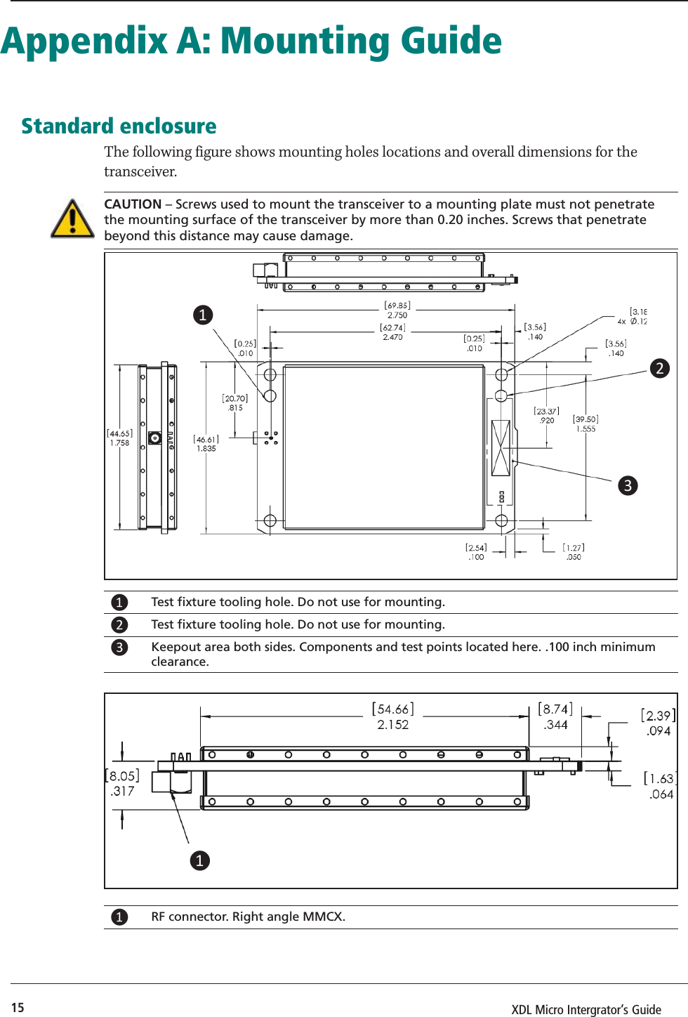
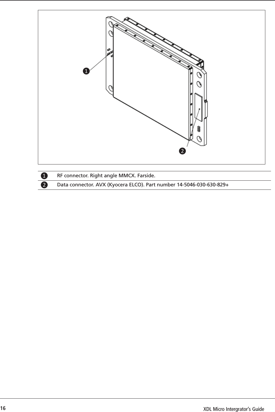
Contents

Users Manual Part Two

1XDL Micro Intergrator’s Guide XDL Micro Integrator’s Guide
2XDL Micro Intergrator’s Guide Contact InformationCustomer support and sales contactsQuality, technology, and service are the hallmarks of Paci c Crest. We provide easy access to our customer service department to keep you running e  ciently.Headquarters EMEA Offi cePaci c Crest HAL Trade Center510 DeGuigne Drive Bevelandseweg 150Sunnyvale, CA 94085 1703 AX HeerhugowaardU.S.A  e NetherlandsTel: 1-800-795-1001 (U.S.A toll free) Tel: +31-72-5348408(408) 481-8070 (outside the U.S.A) Fax: +31-72-5348288Fax: (408) 481-8984Sales email: sales@Paci cCrest.comSupport email: support@Paci cCrest.comRepair info: pccservice@Paci cCrest.comWeb www.Paci cCrest.comSupport hours are 8 am to 5 pm Paci c Time. Please visit our website for up-to-date news and product announcements. Firmware and software upgrades are available from our website, usually free of charge. Legal notices© 2012 Paci c Crest. All rights reserved. Adaptation, or translation of this manual is prohibited without prior written permission of Paci c Crest, except as allowed under the copyright laws.  is document contains proprietary information that is protected by copyright. All rights reserved.   e information contained in this document is subject to change without notice. PORON is a licensed trademark of Rogers Corporation. SATEL is a registered trademark of SATEL Oy. Trimble is a trademark of Trimble Navigation Limited, registered in the United States and in other countries. TRIMMARK and TRIMTALK are trademarks of Trimble Navigation Limited. Microsoft, Windows, and Windows Vista are either registered trademarks or trademarks of Microsoft Corporation in the United States and/or other countries. All trademarks are the property of their respective owners. Release notice  is is the March 2012 release of the XDL Micro Integrator’s  Guide.WarrantyPACIFIC CREST MAKES NO WARRANTY OF ANY KIND WITH REGARD TO THIS MATERIAL, INCLUDING, BUT NOT LIMITED TO, THE IMPLIED WARRANTIES OF MERCHANTABILITY AND FITNESS FOR A PARTICULAR PURPOSE. Paci c Crest shall not be liable for errors contained herein or for incidental consequential damages in connection with the furnishing, performance, or use of this material. WarrantyOne-Year limited warranty  is warranty gives you speci c legal rights. You may also have other rights which vary from state to state or area to area.Paci c Crest warrants XDL family products, inclusive of cables and batteries, against defects in materials and workmanship for a period of one year from receipt by the end-user.ExclusionsShould Paci c Crest be unable to repair or replace the product within a reasonable amount of time, a refund of the purchase price may be given upon return of the product.  e warranty on your radio shall not apply to defects resulting from:•  Improper or inadequate maintenance by the customer• Unauthorized modi cation, negligence, or misuse•  Operation outside of the environment speci cationsWarranty limitations is warranty set forth above is exclusive and no other warranty, whether written or oral, is expressed or implied. Paci c Crest speci cally disclaims the implied warranties of merchantability and  tness for a particular purpose.NoticesClass B Statement – Notice to Users.   is equipment has been tested and found to comply with the limits for a Class B digital device, pursuant to Part 15 of the FCC rules.   ese limits are designed to provide reasonable protection against harmful interference in a residential installation.   is equipment generates, uses, and can radiate radio frequency energy and, if not installed and used in accordance with the instructions, may cause harmful interference to radio communication. However, there is no guarantee that interference will not occur in a particular installation. If this equipment does cause harmful interference to radio or television reception, which can be determined by turning the equipment o  and on, the user is encouraged to try to correct the interference by one or more of the following measures:•  Reorient or relocate the receiving antenna.•  Increase the separation between the equipment and the receiver.•  Connect the equipment into an outlet on a circuit di erent from that to which the receiver is connected.•  Consult the dealer or Paci c Crest directly for help.Changes and modi cations not expressly approved by the manufacturer or registrant of this equipment can void your authority to operate this equipment under Federal Communications Commission rules.Canada  is digital apparatus does not exceed the Class B limits for radio noise emissions from digital apparatus as set out in the radio interference regulations of the Canadian Department of Communications.Le présent appareil numérique n’émet pas de bruits radioélectriques dépassant les limites applicables aux appareils numériques de Classe B prescrites dans le règlement sur le brouillage radioélectrique édicté par le ministère des Communications du Canada.Europe  is product has been tested and found to comply with the requirements for a Class B device pursuant to European Council Directive 1999/5/EC on R&TTE, thereby satisfying the requirements for CE Marking and sale within the European Economic Area (EEA).   ese requirements are designed to provide reasonable protection against harmful interference when the equipment is operated in a residential or commercial environment, and to ensure that the equipment is safe.Australia and New Zealand is product conforms with the regulatory requirements of the Australian Communications and Media Authority (ACMA) EMC framework, thus satisfying the requirements for C-Tick Marking and sale within Australia and New Zealand. Notice to Our European Union CustomersFor product recycling instructions and more information, please go to www.trimble.com/ev.shtml. Recycling in Europe: To recycle Trimble WEEE (Waste Electrical and Electronic Equipment, products that run on electrical power.), Call +31 497 53 24 30, and ask for the “WEEE Associate”. Or, mail a request for recycling instructions to:Trimble Europe BVc/o Menlo Worldwide LogisticsMeerheide 455521 DZ Eersel, NLCompliance   e XDL Micro is designed to be compliant with worldwide regulatory requirements, including FCC part 90, ETS 300-113-2, IC RSS 119 and others. WARNING – The XDL Micro  is classified as an intentional radiator of type radio. Conducted and radiated emissions of the standard XDL Micro do not exceed the requirements of FCC part 90 and ETS 300-113-2. OEM is responsible for full compliance of final product.
3XDL Micro Intergrator’s Guide Safety InformationBefore you use your radio, ensure that you have read and understood this publication, as well as safety requirements.CAUTION – A license is required before operating radio communication equipment.Warnings and cautionsAn absence of specific alerts does not mean that there are no safety risks involved.Always follow the instructions that accompany a Warning or Caution. The information they provide is intended to minimize the risk of personal injury and/or damage to the equipment. In particular, observe safety instructions that are presented in the following formats:WARNING – A Warning alerts you to a likely risk of serious injury to your person and/or damage to the equipment. A warning identifies the nature of the risk and the extent of possible injury and/or damage. It also describes how to protect yourself and/or the equipment from this risk. Warnings that appear in the text are repeated at the front of the manual.CAUTION – A Caution alerts you to a possible risk of damage to the equipment and/or loss of data. A Caution describes how to protect the equipment and/or data from thisExposure to radio frequency energyThe radio is designed to comply with the following national and international standards and guidelines regarding exposure of human beings to radio frequency electromagnetic energy, in addition to protection against harmful interference of neighboring electrical equipment:•  FCC Report and Order FCC 96-326 (August, 1996)•  American National Standards Institute (C95.3-1992)•  National Council on Radiation Protection and Measurement (NCRP - 1986)•  International Commission on Non-ionizing Radiation Protection (ICNRP - 1986)•  European Committee for Electrotechnical Standardization (CENELEC)•  FCC CFR47 Part 15•  FCC CFR47 Part 90•  Industry Canada RSS 119•  ETSI EN 300 113-2•  ETSI EN 300 489•  ACA AS/NZS 4295•  iDA Spec 111• OFTA STD-1E• RRC CMIIContact your sales representative for model specific country approval.
4XDL Micro Intergrator’s Guide To assure optimal radio performance and to ensure that exposure to RF energy is within the guidelines in the above standards, observe the following operating procedures:•  Do not operate a transceiver when someone is within the distance noted below of the antenna (unity gain).  –45 cm (approximately 12 in) for the XDL Micro radio @ 2 W –15 cm (approximately 6 in) for the XDL Micro radio @ 1 W•  Do not operate the transceiver unless all RF connectors are secure and any open connectors are properly terminated.•  Avoid contact with the antenna while operating the transceiver.•  Do not operate the transceiver with a damaged antenna. If a damaged antenna comes in contact with the skin, a minor burn may result.•  Do not operate the equipment near electrical blasting caps or in an explosive atmosphere.CAUTION – Changes or modifications not expressly approved by the FCC could void the user’s authority to operate the equipment.WARNING – The XDL Micro is classified as an intentional radiator of type radio transceiver. Conducted and radiated emissions of the standard XDL Micro do not exceed the requirements of FCC part 90 and ETS 300-113-2. OEM is responsible for full compliance of final product.General cautionsCAUTION – You must handle the XDL Micro with care during installation. Remove the transceiver from its protective bag only in an ESD safe area. CAUTION – Incorrect impedance matching of the antenna, connectors, or cable degrades the performance of the transceiver. CAUTION – Internal circuitry protects the inputs and outputs against damage caused by high static voltages or electric fields. However, normal precautions are necessary to avoid application of any voltage higher than the maximum-rated voltages. CAUTION – Radiated and conducted signals to and from the transceiver may cause problems due to interference. Correct attention to frequency planning may reduce interference from radiated or conducted frequencies that fall within the pass-bands of the filters at the IF frequencies.CAUTION – To avoid interference between the signals, Pacific Crest recommends you do not bundle the antenna interface cable with other signal cables internal to your product.
5XDL Micro Intergrator’s Guide ContentsSafety Information . . . . . . . . . . . . . . . . . . . . . . . . . . . . . . . . . . . . . . . . . . . . . . . . . . . . . . 3Introduction  . . . . . . . . . . . . . . . . . . . . . . . . . . . . . . . . . . . . . . . . . . . . . . . . . . . . . . . . . . . 6Getting Started. . . . . . . . . . . . . . . . . . . . . . . . . . . . . . . . . . . . . . . . . . . . . . . . . . . . . . . . . 7Interface Port Pin Out  . . . . . . . . . . . . . . . . . . . . . . . . . . . . . . . . . . . . . . . . . . . . . . . . . . . . . . . . . . . . . . . . . . . . . 8Transmit and receive pins. . . . . . . . . . . . . . . . . . . . . . . . . . . . . . . . . . . . . . . . . . . . . . . . . . . . . . . . . . . . . . . . . . 9Antenna port . . . . . . . . . . . . . . . . . . . . . . . . . . . . . . . . . . . . . . . . . . . . . . . . . . . . . . . . . . . . . . . . . . . . . . . . . . . . . . 9Compatibility. . . . . . . . . . . . . . . . . . . . . . . . . . . . . . . . . . . . . . . . . . . . . . . . . . . . . . . . . . . . . . . . . . . . . . . . . . . . . . 9Protocols and Operation Modes . . . . . . . . . . . . . . . . . . . . . . . . . . . . . . . . . . . . . . . . . . 10Electrical Considerations . . . . . . . . . . . . . . . . . . . . . . . . . . . . . . . . . . . . . . . . . . . . . . . . 11Power supply   . . . . . . . . . . . . . . . . . . . . . . . . . . . . . . . . . . . . . . . . . . . . . . . . . . . . . . . . . . . . . . . . . . . . . . . . . . . . . . . . 11Data interface  . . . . . . . . . . . . . . . . . . . . . . . . . . . . . . . . . . . . . . . . . . . . . . . . . . . . . . . . . . . . . . . . . . . . . . . . . . . . . . . 11CMOS input/output protection circuitry  . . . . . . . . . . . . . . . . . . . . . . . . . . . . . . . . . . . . . . . . . . . . . . . . . . . . . 11NC pins . . . . . . . . . . . . . . . . . . . . . . . . . . . . . . . . . . . . . . . . . . . . . . . . . . . . . . . . . . . . . . . . . . . . . . . . . . . . . . . . . . . . . . 11Power down pin. . . . . . . . . . . . . . . . . . . . . . . . . . . . . . . . . . . . . . . . . . . . . . . . . . . . . . . . . . . . . . . . . . . . . . . . . . . . . . 12Error codes . . . . . . . . . . . . . . . . . . . . . . . . . . . . . . . . . . . . . . . . . . . . . . . . . . . . . . . . . . . . . . . . . . . . . . . . . . . . . . . 12Shielding considerations. . . . . . . . . . . . . . . . . . . . . . . . . . . . . . . . . . . . . . . . . . . . . . . . . . . . . . . . . . . . . . . . . . 12Frequency planning  . . . . . . . . . . . . . . . . . . . . . . . . . . . . . . . . . . . . . . . . . . . . . . . . . . . . . . . . . . . . . . . . . . . . . . 13Mechanical Considerations . . . . . . . . . . . . . . . . . . . . . . . . . . . . . . . . . . . . . . . . . . . . . . 14EMI interferers. . . . . . . . . . . . . . . . . . . . . . . . . . . . . . . . . . . . . . . . . . . . . . . . . . . . . . . . . . . . . . . . . . . . . . . . . . . . . . . 14Shock and vibration . . . . . . . . . . . . . . . . . . . . . . . . . . . . . . . . . . . . . . . . . . . . . . . . . . . . . . . . . . . . . . . . . . . . . . . . . . 14  ermal transfer . . . . . . . . . . . . . . . . . . . . . . . . . . . . . . . . . . . . . . . . . . . . . . . . . . . . . . . . . . . . . . . . . . . . . . . . . . . . . 14Materials. . . . . . . . . . . . . . . . . . . . . . . . . . . . . . . . . . . . . . . . . . . . . . . . . . . . . . . . . . . . . . . . . . . . . . . . . . . . . . . . . . . . . 14Appendix A: Mounting Guide . . . . . . . . . . . . . . . . . . . . . . . . . . . . . . . . . . . . . . . . . . . . 15Standard enclosure. . . . . . . . . . . . . . . . . . . . . . . . . . . . . . . . . . . . . . . . . . . . . . . . . . . . . . . . . . . . . . . . . . . . . . . . . . . 15Appendix B: Cables and Connectors . . . . . . . . . . . . . . . . . . . . . . . . . . . . . . . . . . . . . . . 17Value-added cable products . . . . . . . . . . . . . . . . . . . . . . . . . . . . . . . . . . . . . . . . . . . . . . . . . . . . . . . . . . . . . . . . . . 17Interface connector . . . . . . . . . . . . . . . . . . . . . . . . . . . . . . . . . . . . . . . . . . . . . . . . . . . . . . . . . . . . . . . . . . . . . . . . . . 17RF connector. . . . . . . . . . . . . . . . . . . . . . . . . . . . . . . . . . . . . . . . . . . . . . . . . . . . . . . . . . . . . . . . . . . . . . . . . . . . . . . . . 17Appendix C: Technical Specifi cations  . . . . . . . . . . . . . . . . . . . . . . . . . . . . . . . . . . . . . . 18Appendix D: API Commands . . . . . . . . . . . . . . . . . . . . . . . . . . . . . . . . . . . . . . . . . . . . . 19
6XDL Micro Intergrator’s Guide IntroductionThis manual describes how to integrate the XDL Micro UHF transceiver (model numbers XDLM-0, XDLM-1 and XDLM-2) into your product. Pacific Crest recommends that you also read the XDLCONF User’s Guide for general information about configuring XDL Micro modems, and for detailed programming information. The XDL Micro is a general-purpose transceiver. It is compatible with the Pacific Crest ADL, PDL and RFM product families of radio modems. It is also compatbile with radios configured to use the SATEL®, South, Stonex Type 1, and Trimble TRIMTALK™ and TRIMMARK™ protocols. The XDL Micro transceiver is designed specifically for integration into new or existing products. Its small size, light weight, and power efficient operation provide superior performance in embedded systems. Legal restrictionsThe XDL Micro transceiver may be programmed to transmit only in accordance with a license issued by the radio authority of the country of operation. In the United States, this authority is the Federal Communications Commission (FCC).  It is a violation of FCC rules if the XDL Micro operates on unlicensed frequencies or channel bandwidths.  The XDL Micro uses extended frequencies and may contain functions that are not operational in the United States and its territories. Users should check with the radio authority of the country of operation for any restrictions that might apply.Technical supportIf you have a problem and cannot find the information you need in the product documentation, contact your local dealer or go to the Support area of the Pacific Crest website (www.pacificcrest.com/support.php). Product updates, documentation, and any support issues are available for download.If you need to contact technical support, email support@pacificcrest.com.  Your commentsYour feedback about the supporting documentation helps us to improve it with each revision. Email your comments to  info@pacificcrest.com.
7XDL Micro Intergrator’s Guide Getting StartedCAUTION – You must handle the XDL Micro transceiver with care during installation. Remove the transceiver from its protective bag only in an ESD safe area. To set up the hardware components:1.  Plug the transceiver into the 30-pin connector of an I/O-test board.2.  Attach an antenna to the transceiver using an XDL radio module pigtail data cable.3.  Attach a modem cable to a 9-pin RS232 connector on the I/O-test board.4.  Attach the modem cable to a serial port on the computer.5.  Attach a wall cable to the AC/DC adapter and then select the correct plug from the adapter kit.6.  Attach the AD/DC adapter’s tubular plug to the power jack on the I/O-test board.7.  Install the XDLCONF software on the computer.8.  Start the XDLCONF software and then connect to the transceiver.Figure 1 – XDL Micro in test board
8XDL Micro Intergrator’s Guide Interface Port Pin OutThe standard XDL Micro transceiver comprises a 30-pin port for power, data, and interfacing with other electronic devices. The following signals are available on the 30-pin connector: Pin number Function Description1 GND Ground for signal and power2 NC No Connection, Factory use only3 TX Data Receives data from external device, 3 V CMOS (3.3 V compatible)4 NC No Connection, Factory use only5 GND Ground for signal and power6 NC No Connection, Factory use only7 GND Ground for signal and power8 NC No Connection, Factory use only9 GND Ground for signal and power10 NC No Connection, Factory use only11 Configure  No Connection, Factory use only12 NC No Connection, Factory use only13 NC No Connection, Factory use only14 RX Data Sends data to external device, 3 V CMOS (3.3 V compatible)15 NC No Connection, Factory use only16 NC No Connection, Factory use only17 NC No Connection, Factory use only18 VCC Power In19 GND Ground for signal and power20 GND Ground for signal and power21 GND Ground for signal and power22 GND Ground for signal and power23 VCC Power In24 VCC Power In25 VCC Power In26 VCC Power In27 VCC Power In28 VCC Power In29 Power Down Power down radio30 GND Ground for signal and power
9XDL Micro Intergrator’s Guide Transmit and receive pinsThe XDL Micro module uses pin 3 to receive data from an external device, such as a computer, GPS receiver, or weather sensor, and uses pin 14 to transmit data to the external device. The external device transmits data to the XDL Micro transceiver on pin 3, so according to the DTE naming convention, pin 3 is called the Tx Data pin. The external device receives data from pin 14 on the XDL Micro transceiver, so this is called the Rx Data pin.Antenna portA coaxial antenna port is provided to connect the antenna system to the transceiver. The antenna connector is a 50-Ohm MMCX type. Appendix B: Cables and Connectors, page 17 provides part numbers and manufacturer information for compatible interface and RF connectors. Pacific Crest also provides custom manufactured cables designed to your specific needs. For specific cabling requirements, please contact us for a quotation.CAUTION – Do not transmit without first connecting an antenna as it may damage the transceiver.CompatibilityThe transceiver is compatible with most modes of operation supported by the XDL, ADL and PDL product families of radio modems. For an overview of the protocols and modes that the transceiver supports, see Protocols and Operation Modes, page 10. The compatibility also extends to the XDLCONF configuration software and the XDL Test application that are supplied as part of the XDL Micro Developer’s Kit (P/N 70888-88).
10 XDL Micro Intergrator’s Guide  Protocols and Operation ModesYou can completely configure the transceiver using the XDLCONF software. Configuration parameters define the DTE interface and the over-the-air protocol. Depending on your application, you may need to change the factory default settings.The following table shows the factory default settings of the transceiver.Setting Default settingChannel 1Baud Rate 38400Parity NoneSoft Break Disable OffTX Power 0.5 WMode Transparent EOT TimeoutLink Rate 9600 bps GMSKEOT 50 msRepeater Delay 0CSMA On (CSMA is required to be on only in the U.S.A. You should turn off CSMA in the European Union.)FEC OnScrambling OnSensitivity HighLocal Address 0Destination address 255Up to 32 frequencies are stored in the configuration memory called the channel table. The selection of channels is subject to correct licensing of the corresponding frequencies by the appropriate governmental agency. For instructions in creating and uploading channel tables into the transceiver, refer to the XDLCONF User’s Guide.The transceiver supports multiple protocols and modes of operation including:•  Transparent with EOT Timeout•  Transparent with EOT Character• TRIMTALK II/IIe• TRIMTALK 450S• TRIMMARK 3• SATEL• South•  Stonex Type 1• Transparent FST
11 XDL Micro Intergrator’s Guide Electrical ConsiderationsPower supply The transceiver has a power supply connection on pins 18, 23, 24, 25, 26, 27, and 28 of the interface connector. If there is a potential for a ground path current loop due to incorrect power application, Pacific Crest recommends that you insert a fusible link in the signal ground to protect the transceiver. The XDL Micro transceiver is designed to operate with an unregulated DC voltage level at 3.6 ±0.4V. The power supply must be capable of sourcing 2 A. Data interface The transceiver has one serial port. It is a data port that has a simple 3-wire CMOS electrical interface with signals for transmitting data to, and receiving data from, the transceiver, and for providing a reference ground for the Tx (pin 3) and Rx (pin 14) signals. Note– Pacific Crest defines Tx and Rx as a DTE port. That is, an external device transmits data to the radio modem’s Tx pin (pin 3) and receives data from the radio modem’s Rx pin (pin 14).CMOS input/output protection circuitry The Tx signal terminates into a CMOS input port on the transceiver and should be driven externally or pulled to ground through a 10 kΩ resistor. The absolute maximum voltage applied to the Tx signal is -0.3 v to 3.3 V. The Rx signal is CMOS outputs. Note that loading the RX signal increases the power consumption of the transceiver and these should be limited to no more than 2.5 mA in order to maintain performance across the temperature range. CAUTION – Internal circuitry protects the inputs and outputs against damage caused by high static voltages or electric fields. However, normal precautions are necessary to avoid application of any voltage higher than the maximum-rated voltages. NC pinsPins 2, 4, 6, 8, 10, 12, 13, and 15 through 17 must be left with no connection.
12 XDL Micro Intergrator’s Guide Power down pinPin 29 is the active low pin used to turn off power to the XDL Micro transceiver. The VIH (Voltage Input High) minimum is 1.2 V and VIL (Voltage Input Low) maximum is 0.3 V. It has a 10 K pull-up resistor to VCC. You can leave it unconnected (NC) if you do not want to turn off the XDL Micro transceiver.Error codesThe transceiver performs a variety of start-up and run-time tests to ensure optimal operation. Tests include environmental as well as electrical measurements designed to avoid damage to the unit while maintaining adequate operation. A 50 Ω impedance coaxial MMCX style RF connector is provided to attach to an external antenna system. The MMCX connector offers a positive friction locking mechanism that is very reliable. In some circumstances it may be required to provide a physical stop to prevent the MMCX plug from becoming disconnected due to extreme shock or vibration.The transceiver requires an antenna and feed cable system that is impedance-matched to 50 Ω. Pacific Crest recommends that you use a high-quality RG-178 or equivalent coaxial cable for internal wiring of the RF signal from the MMCX connector to the panel connector. Pacific Crest also recommends you select an antenna that has a low VSWR (Voltage Standing Wave Ratio) (less than 1.5:1) and which is tuned for operation in the band of the XDL Micro transceiver. CAUTION – Incorrect impedance matching of the antenna, connectors, or cable degrades the performance of the transceiver. Shielding considerationsThe transceiver is designed to operate in proximity to noise-generating circuitry. However, certain radiated or conducted frequencies may degrade the performance of the transceiver or make it inoperable. When possible, provide well-grounded shielding between the transceiver and radiating circuits, such as power supplies, voltage-controlled oscillators, and crystal oscillators.
13 XDL Micro Intergrator’s Guide Frequency planning The transceiver contains a very sensitive, dual-conversion, super-heterodyne receiver.CAUTION – Radiated and conducted signals to and from the transceiver may cause problems due to interference. Correct attention to frequency planning may reduce interference from radiated or conducted frequencies that fall within the pass-bands of the filters at the IF frequencies. Pacific Crest recommends you first analyse the product frequency plan (including harmonics) and then use a spectrum analyzer to determine the potential for interference within the pass-bands of the various front-end and band pass filters. The following table indicates the frequencies and pass-band filter characteristics that are areas of potential interference.Circuit Center frequency (MHz) Bandwidth (MHz)RF front-end 438 70First IF 54.45 0.015Second IF 0.450 0.010
14 XDL Micro Intergrator’s Guide Mechanical ConsiderationsEMI interferersThe transceiver is easily mounted in new and existing products. The transceiver is specifically designed for operation in harsh environments. For best performance, mount the radio away from potential EMI radiators and route RF signals apart from digital signals. CAUTION – To avoid interference between the signals, Pacific Crest recommends you do not bundle the antenna interface cable with other signal cables internal to your product.Shock and vibrationSensitive receivers, such as that in the XDL Micro transceiver, are susceptible to interference due to mechanical shock and vibration. To reduce the potential for electromechanical interference, you must use a robust mounting scheme when you integrate the transceiver into other systems. You may need to use a thin damping pad between the mounting surface and the transceiver. Pacific Crest recommends that the damping pads you use are made of PORON® or a similar material. Thermal transferThe transceiver requires additional thermal heat dissipation in order to supply maximum output power at elevated ambient temperatures and high-duty cycles. The transceiver has a thermal sensor and a firmware controlled limit switch. To prevent permanent damage to the transmitter, the XDL Micro module shuts down when its internal temperature reaches 85 °C (185 °F). The integrated heat sink is adequate for most bench top testing, but when the transceiver is integrated into other systems you must consider additional thermal heat sinking. The transceiver produces approximately 6 Watts of heat at full RF power out. For mounting diagrams and specification, see Appendix A: Mounting Guide, page 15. MaterialsThe transceiver is housed in a metal shield that is a conductor and is electrically connected to the ground and signal ground pins.
15 XDL Micro Intergrator’s Guide  Appendix A: Mounting GuideStandard enclosureThe following figure shows mounting holes locations and overall dimensions for the transceiver. CAUTION – Screws used to mount the transceiver to a mounting plate must not penetrate the mounting surface of the transceiver by more than 0.20 inches. Screws that penetrate beyond this distance may cause damage.❸ ❶ ❷ ❶Test fixture tooling hole. Do not use for mounting.❷Test fixture tooling hole. Do not use for mounting.❸Keepout area both sides. Components and test points located here. .100 inch minimum clearance.❶❶RF connector. Right angle MMCX.
16 XDL Micro Intergrator’s Guide ❶RF connector. Right angle MMCX. Farside.❷Data connector. AVX (Kyocera ELCO). Part number 14-5046-030-630-829+❶❷
17 XDL Micro Intergrator’s Guide  Appendix B: Cables and ConnectorsValue-added cable productsPacific Crest manufactures a wide variety of high-quality custom cables to support its OEM customers. To discuss your custom cable requirements, contact your Pacific Crest sales representative.Interface connectorThe 30-pin data/power header is an AVX Series 5046 fine-pitch connector, AVX part number AVX 24-5046-030-630-829. The mating AVX connector is part number AVX 24-5046-030-600-829for a board-to-board interface that is coincident with the mounting hardware.  RF connectorThe RF connector is compatible with an MMCX-style coaxial plug. Plugs are available from many sources and in many configurations. Pacific Crest uses plugs manufactured by Radiall. Radiall MMCX right-angle plug for use with RG-178 cable is part number R110 172 100. Radiall MMCX straight plug for use with RG-178 cable is part number R110 083 120.
18 XDL Micro Intergrator’s Guide Appendix C: Technical SpecificationsGeneralDTE - DCE interface CMOS, 115.2 kbps maximumPower requirementsExternal 3.6 VDC ± 0.05mVDuring Rx 0.45 W nominal @ 3.6 VDCDuring Tx 6.5 W nominal @ 3.6 VDC, 2 W RF outputRadioFrequency band 403-473 MHzFrequency control Synthesized 12.5 kHz tuning resolutionFrequency stability +/- 1PPMChannel spacing Channel spacing 12.5/25 kHz (user-selectable)RF transmitter output 0.5, 1.0 or 2 Watt (Programmable)Sensitivity -110 dBm BER = 1 x 10⁻⁵Adjacent channel selectivity>50dBType certification All models will be type accepted and certified for operation in the U.S., Europe, Australia, New Zealand, and CanadaFCC, IC, EU, NZ, Australia ETS300-113-2ModemLink Rate/Modulation 4-Level FSK: 9600, 19,200 bpsGMSK: 4800, 8000, 9600, 16,000, 19,200 bpsLink Protocols Transparent EOT/EOC/FST, SATEL, South, Stonex Type 1, TRIMTALK II/IIe, TRIMMARK3, TRIMTALK 450SForward Error Correction (FEC) and DetectionYesEnvironmentalShock and vibration Per MIL-STD-810FAmbient temperature rangeOperating temperature (receiver)-40 ˚C to +85 ˚C  (-40 ˚F to +185 ˚F)Operating temperature (transmitter)-40 ˚C to +65 ˚C  (-22 ˚F to +149 ˚F)Storage temperature -55 ˚C to +85 ˚C  (-67 ˚F to +185 ˚F)MechanicalDimensions 69.8 mm L x 46.6 mm W x 11.2 mm H2.750” L x 1.835” W x 0.442” HWeight 1.4 oz (40 grams)
19 XDL Micro Intergrator’s Guide Appendix D: API CommandsA description of the XDL Micro transceiver Application Programmer Interface is available to qualified Pacific Crest development partners. Please contact sales@PacificCrest.com.

Navigation menu