Trimble 029A-SN450 Ruggedized Data Modem for GPS User Manual SiteNet 450 Operation Manual
Trimble Navigation Ltd Ruggedized Data Modem for GPS SiteNet 450 Operation Manual
UserManual.wiki
>
Trimble
>
029A SN450 User Manual
SN450
Navigation menu
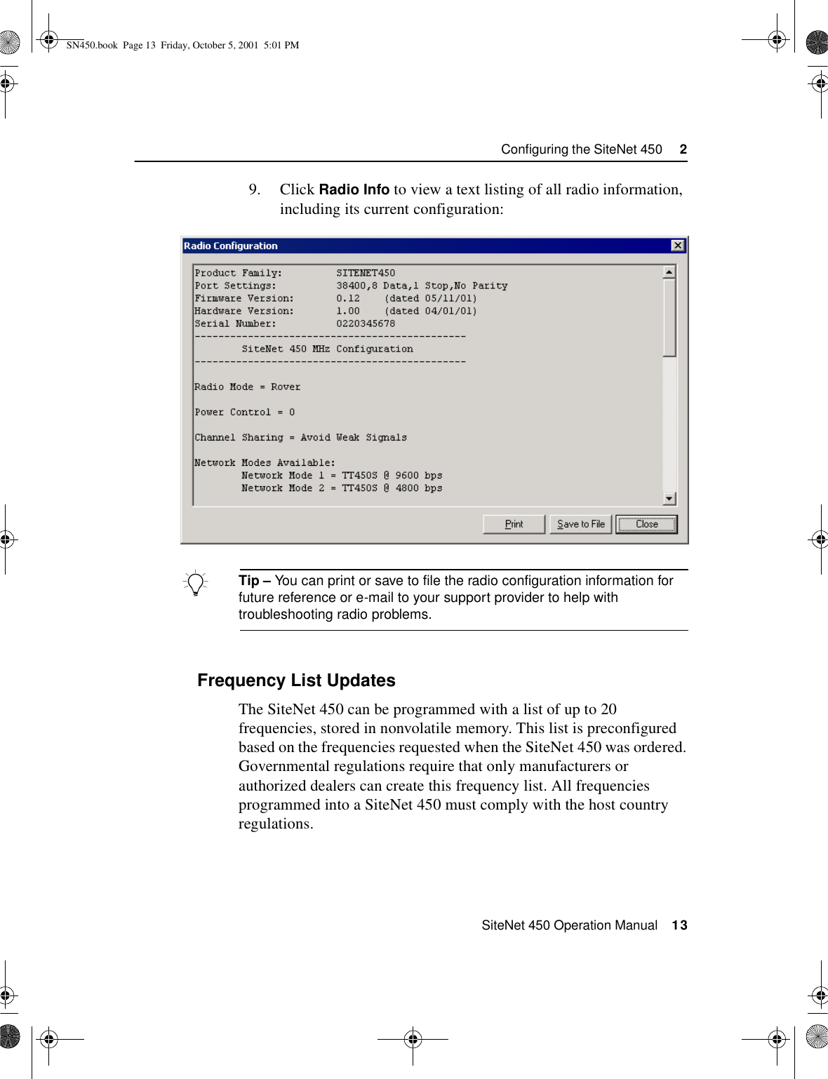
Upload a User Manual
Namespaces
Wiki Guide
HTML
PDF
Info
Views
User Manual
Discussion / Help
Navigation

![About this ManualSiteNet 450 Operation Manual ixYour CommentsYour feedback about the supporting documentation helps us to improve it with each revision. To forward your comments, do one of the following:•Send an e-mail to ReaderFeedback@trimble.com.•Complete the Reader Comment Form at the back of this manual and mail it according to the instructions at the bottom of the form. If the reader comment form is not available, send comments and suggestions to the address in the front of this manual. Please mark it Attention: Technical Publications Group. Document ConventionsThe document conventions are as follows:Convention DefinitionItalics Identifies software menus, menu commands, dialog boxes, and the dialog box fields.Helvetica Narrow Represents messages printed on the screen.Helvetica Bold Identifies a software command button, or represents information that you must type in a software screen or window.“Select Italics /Italics” Identifies the sequence of menus, commands, or dialog boxes that you must choose in order to reach a given screen.[Ctrl] Is an example of a hardware function key that you must press on a personal computer (PC). If you must press more than one of these at the same time, this is represented by a plus sign, for example, [Ctrl]+[C].SN450.book Page ix Friday, October 5, 2001 5:01 PM](https://usermanual.wiki/Trimble/029A-SN450/User-Guide-180280-Page-9.png)