Trimble 029A-SN450 Ruggedized Data Modem for GPS User Manual SiteNet 450 Operation Manual
Trimble Navigation Ltd Ruggedized Data Modem for GPS SiteNet 450 Operation Manual
Trimble >
SN450
F
Part Number 45423-00-ENG
Revision A
October 2001
SiteNet™ 450
Operation Manual
SN450.book Page 1 Friday, October 5, 2001 5:01 PM
Corporate Office
Trimble Navigation Limited
Engineering and Construction
5475 Kellenburger Road
Dayton, Ohio 45424-1099
U.S.A.
Phone: +1-937-233-8921
Toll free:+1-800-538-7800
Fax: +1-937-233-9441
www.trimble.com
Copyright and Trademarks
© 2001, Trimble Navigation Limited. All rights
reserved.
The Globe & Triangle logo, Trimble, 4700, 4800,
5700, MS750, MS850, MS860, SiteNet,
SiteVision, TRIMCOMM, TRIMMARK,
TRIMTALK, and WinFLASH are trademarks of
Trimble Navigation Limited.
The Sextant logo with Trimble and BladePro 3D
are trademarks of Trimble Navigation Limited,
registered in the United States Patent and
Trademark Office.
All other trademarks are the property of their
respective owners.
Release Notice
This is the October 2001 release (Revision A) of
the SiteNet 450 Operation Manual, part number
45423-00-ENG.
The following limited warranties give you specific
legal rights. You may have others, which vary
from state/jurisdiction to state/jurisdiction.
Hardware Limited Warranty
Trimble warrants that this Trimble hardware
product (the “Product”) shall be free from defects
in materials and workmanship and will
substantially conform to Trimble’s applicable
published specifications for the Product for a
period of one (1) year, starting from the date of
delivery. The warranty set forth in this paragraph
shall not apply to software/firmware products.
Software and Firmware License, Limited
Warranty
This Trimble software and/or firmware product
(the “Software”) is licensed and not sold. Its use is
governed by the provisions of the applicable End
User License Agreement (“EULA”), if any,
included with the Software. In the absence of a
separate EULA included with the Software
providing different limited warranty terms,
exclusions, and limitations, the following terms
and conditions shall apply. Trimble warrants that
this Trimble Software product will substantially
conform to Trimble’s applicable published
specifications for the Software for a period of
ninety (90) days, starting from the date of
delivery.
Warranty Remedies
Trimble's sole liability and your exclusive remedy
under the warranties set forth above shall be, at
Trimble’s option, to repair or replace any Product
or Software that fails to conform to such warranty
(“Nonconforming Product”), or refund the
purchase price paid by you for any such
Nonconforming Product, upon your return of any
Nonconforming Product to Trimble in accordance
with Trimble’s standard return material
authorization procedures.
SN450.book Page 2 Friday, October 5, 2001 5:01 PM
Warranty Exclusions and Disclaimer
These warranties shall be applied only in the event
and to the extent that: (i) the Products and
Software are properly and correctly installed,
configured, interfaced, maintained, stored, and
operated in accordance with Trimble’s relevant
operator's manual and specifications, and; (ii) the
Products and Software are not modified or
misused. The preceding warranties shall not apply
to, and Trimble shall not be responsible for defects
or performance problems resulting from (i) the
combination or utilization of the Product or
Software with products, information, data,
systems or devices not made, supplied or specified
by Trimble; (ii) the operation of the Product or
Software under any specification other than, or in
addition to, Trimble's standard specifications for
its products; (iii) the unauthorized modification or
use of the Product or Software; (iv) damage
caused by accident, lightning or other electrical
discharge, fresh or salt water immersion or spray;
or (v) normal wear and tear on consumable parts
(e.g., batteries).
THE WARRANTIES ABOVE STATE TRIMBLE'S
ENTIRE LIABILITY, AND YOUR EXCLUSIVE
REMEDIES, RELATING TO PERFORMANCE OF
THE PRODUCTS AND SOFTWARE. EXCEPT AS
OTHERWISE EXPRESSLY PROVIDED HEREIN,
THE PRODUCTS, SOFTWARE, AND
ACCOMPANYING DOCUMENTATION AND
MATERIALS ARE PROVIDED “AS-IS” AND
WITHOUT EXPRESS OR IMPLIED WARRANTY
OF ANY KIND BY EITHER TRIMBLE
NAVIGATION LIMITED OR ANYONE WHO HAS
BEEN INVOLVED IN ITS CREATION,
PRODUCTION, INSTALLATION, OR
DISTRIBUTION, INCLUDING, BUT NOT LIMITED
TO, THE IMPLIED WARRANTIES OF
MERCHANTABILITY AND FITNESS FOR A
PARTICULAR PURPOSE, TITLE, AND
NONINFRINGEMENT. THE STATED EXPRESS
WARRANTIES ARE IN LIEU OF ALL
OBLIGATIONS OR LIABILITIES ON THE PART
OF TRIMBLE ARISING OUT OF, OR IN
CONNECTION WITH, ANY PRODUCTS OR
SOFTWARE. SOME STATES AND
JURISDICTIONS DO NOT ALLOW LIMITATIONS
ON DURATION OR THE EXCLUSION OF AN
IMPLIED WARRANTY, SO THE ABOVE
LIMITATION MAY NOT APPLY TO YOU.
TRIMBLE NAVIGATION LIMITED IS NOT
RESPONSIBLE FOR THE OPERATION OR
FAILURE OF OPERATION OF GPS SATELLITES
OR THE AVAILABILITY OF GPS SATELLITE
SIGNALS.
Limitation of Liability
TRIMBLE’S ENTIRE LIABILITY UNDER ANY
PROVISION HEREIN SHALL BE LIMITED TO
THE GREATER OF THE AMOUNT PAID BY YOU
FOR THE PRODUCT OR SOFTWARE LICENSE OR
U.S.$25.00. TO THE MAXIMUM EXTENT
PERMITTED BY APPLICABLE LAW, IN NO
EVENT SHALL TRIMBLE OR ITS SUPPLIERS BE
LIABLE FOR ANY INDIRECT, SPECIAL,
INCIDENTAL, OR CONSEQUENTIAL DAMAGES
WHATSOEVER UNDER ANY CIRCUMSTANCE
OR LEGAL THEORY RELATING IN ANY WAY
TO THE PRODUCTS, SOFTWARE, AND
ACCOMPANYING DOCUMENTATION AND
MATERIALS, (INCLUDING, WITHOUT
LIMITATION, DAMAGES FOR LOSS OF
BUSINESS PROFITS, BUSINESS INTERRUPTION,
LOSS OF BUSINESS INFORMATION, OR ANY
OTHER PECUNIARY LOSS), REGARDLESS OF
WHETHER TRIMBLE HAS BEEN ADVISED OF
THE POSSIBILITY OF ANY SUCH LOSS AND
REGARDLESS OF THE COURSE OF DEALING
WHICH DEVELOPS OR HAS DEVELOPED
BETWEEN YOU AND TRIMBLE. BECAUSE SOME
STATES AND JURISDICTIONS DO NOT ALLOW
THE EXCLUSION OR LIMITATION OF LIABILITY
FOR CONSEQUENTIAL OR INCIDENTAL
DAMAGES, THE ABOVE LIMITATION MAY NOT
APPLY TO YOU.
SN450.book Page 3 Friday, October 5, 2001 5:01 PM
Notices
Class B Statement – Notice to Users. This
equipment has been tested and found to comply
with the limits for a Class B digital device,
pursuant to Part 15 of the FCC rules. These limits
are designed to provide reasonable protection
against harmful interference in a residential
installation. This equipment generates, uses, and
can radiate radio frequency energy and, if not
installed and used in accordance with the
instructions, may cause harmful interference to
radio communication. However, there is no
guarantee that interference will not occur in a
particular installation. If this equipment does
cause harmful interference to radio or television
reception, which can be determined by turning the
equipment off and on, the user is encouraged to
try to correct the interference by one or more of
the following measures:
–Reorient or relocate the receiving antenna.
–Increase the separation between the equipment
and the receiver.
–Connect the equipment into an outlet on a
circuit different from that to which the receiver
is connected.
–Consult the dealer or an experienced radio/TV
technician for help.
Changes and modifications not expressly
approved by the manufacturer or registrant of this
equipment can void your authority to operate this
equipment under Federal Communications
Commission rules.
Broadcast frequency, transmit power, channel
spacing and antenna gain are regulated by
countries-of-use. These are unique on a
per-country basis. The broadcast frequencies,
channel spacing, and country-of-use for the
radio-modem must be specified at time of order.
Contact your local Trimble representative for
further information. Specifications and
descriptions are subject to change without notice.
SN450.book Page 4 Friday, October 5, 2001 5:01 PM
SiteNet 450 Operation Manual v
Contents
About this Manual
1 Getting Started
Introduction . . . . . . . . . . . . . . . . . . . . . . . . . . . . . . . . 2
Hardware Specification . . . . . . . . . . . . . . . . . . . . . . . . . . 2
SiteNet 450 Description. . . . . . . . . . . . . . . . . . . . . . . . . . 3
Features. . . . . . . . . . . . . . . . . . . . . . . . . . . . . . . 3
Options . . . . . . . . . . . . . . . . . . . . . . . . . . . . . . . 3
Frequency Band . . . . . . . . . . . . . . . . . . . . . . . . . . 4
2 Configuring the SiteNet 450
Introduction . . . . . . . . . . . . . . . . . . . . . . . . . . . . . . . . 6
Default Settings . . . . . . . . . . . . . . . . . . . . . . . . . . . . . . 6
Configuration . . . . . . . . . . . . . . . . . . . . . . . . . . . . . . . 6
Connecting to the SiteNet 450 . . . . . . . . . . . . . . . . . . . 7
Starting WinFLASH . . . . . . . . . . . . . . . . . . . . . . . . 7
Configuring the SiteNet 450 . . . . . . . . . . . . . . . . . . . 10
Frequency List Updates . . . . . . . . . . . . . . . . . . . . . 13
Software Updates. . . . . . . . . . . . . . . . . . . . . . . . . 14
3 Installing the SiteNet 450 Network
Introduction . . . . . . . . . . . . . . . . . . . . . . . . . . . . . . . 16
Physical Description . . . . . . . . . . . . . . . . . . . . . . . . . . 17
Connectors and Indicators . . . . . . . . . . . . . . . . . . . . 18
Mounting the SiteNet 450 on a Machine . . . . . . . . . . . . . . . . 21
Machine Mount Kit (PN 35087-00) . . . . . . . . . . . . . . . 21
SN450.book Page v Friday, October 5, 2001 5:01 PM

Contents
vi SiteNet 450 Operation Manual
Cabling Configurations . . . . . . . . . . . . . . . . . . . . . . . . . 25
Power and I/O Cable for Machine Installations . . . . . . . . . 26
Infrastructure/Base Station Power and I/O Cable . . . . . . . . 27
Machine Service Cable. . . . . . . . . . . . . . . . . . . . . . 31
Antenna Description . . . . . . . . . . . . . . . . . . . . . . . . . . 32
Antenna Considerations . . . . . . . . . . . . . . . . . . . . . 33
4 Regulations and Safety
Introduction . . . . . . . . . . . . . . . . . . . . . . . . . . . . . . . 38
Type Approval. . . . . . . . . . . . . . . . . . . . . . . . . . . . . . 38
Licensing . . . . . . . . . . . . . . . . . . . . . . . . . . . . . . . . 39
Safety . . . . . . . . . . . . . . . . . . . . . . . . . . . . . . . . . . 39
A Technical Specifications
Technical Information. . . . . . . . . . . . . . . . . . . . . . . . . . 42
Pinout Information . . . . . . . . . . . . . . . . . . . . . . . . . . . 44
B Using Radios with GPS
Introduction . . . . . . . . . . . . . . . . . . . . . . . . . . . . . . . 46
Selecting Communications Radios . . . . . . . . . . . . . . . . . . . 47
Useful Field Procedures. . . . . . . . . . . . . . . . . . . . . . . . . 49
Summary . . . . . . . . . . . . . . . . . . . . . . . . . . . . . . . . 50
Index
SN450.book Page vi Friday, October 5, 2001 5:01 PM
SiteNet 450 Operation Manual vii
About this Manual
Welcome to the SiteNet 450 Operation Manual. This manual describes
how to install, set up, and use the SiteNet™ 450 radio-modem.
Even if you have used other radio-modems before, Trimble
recommends that you spend some time reading this manual to learn
about the special features of this product.
If you are not familiar with GPS, visit Trimble’s website
(www.trimble.com) for an interactive look at Trimble and GPS.
SN450.book Page vii Friday, October 5, 2001 5:01 PM

About this Manual
viii SiteNet 450 Operation Manual
Related Information
Other sources of related information are:
•Release notes – the release notes describe new features of the
product, information not included in the manuals, and any
changes to the manuals.
•Update notes – there is a warranty activation sheet with this
product. Send it in to automatically receive update notes
containing important information about software and hardware
changes. Contact your local Trimble Dealer for more
information about the support agreement contracts for software
and firmware, and an extended warranty program for hardware.
•Look at the Trimble website support page at
www.trimble.com/support/ for additional information such as:
technical tips, service bulletins, and FAQs. Also, you can
download software patches, firmware and utility programs.
•Trimble training courses – consider a training course to help
you use your GPS system to its fullest potential. For more
information, visit the Trimble website at
www.trimble.com/support.
Technical Assistance
If you have a problem and cannot find the information you need in the
product documentation, contact your local distributor.
SN450.book Page viii Friday, October 5, 2001 5:01 PM

About this Manual
SiteNet 450 Operation Manual ix
Your Comments
Your feedback about the supporting documentation helps us to
improve it with each revision. To forward your comments, do one of
the following:
•Send an e-mail to ReaderFeedback@trimble.com.
•Complete the Reader Comment Form at the back of this manual
and mail it according to the instructions at the bottom of the
form.
If the reader comment form is not available, send comments and
suggestions to the address in the front of this manual. Please mark it
Attention: Technical Publications Group.
Document Conventions
The document conventions are as follows:
Convention Definition
Italics Identifies software menus, menu commands,
dialog boxes, and the dialog box fields.
Helvetica Narrow Represents messages printed on the screen.
Helvetica Bold Identifies a software command button, or
represents information that you must type in a
software screen or window.
“Select Italics /Italics” Identifies the sequence of menus, commands, or
dialog boxes that you must choose in order to
reach a given screen.
[Ctrl] Is an example of a hardware function key that you
must press on a personal computer (PC). If you
must press more than one of these at the same
time, this is represented by a plus sign, for
example, [Ctrl]+[C].
SN450.book Page ix Friday, October 5, 2001 5:01 PM

About this Manual
x SiteNet 450 Operation Manual
SN450.book Page x Friday, October 5, 2001 5:01 PM

CHAPTER
1
Getting Started
1
In this chapter:
■Introduction
■Hardware Specification
■SiteNet 450 Description
SN450.book Page 1 Friday, October 5, 2001 5:01 PM

1 Getting Started
2 SiteNet 450 Operation Manual
1.1
Introduction
The SiteNet 450 radio-modem broadcasts raw GPS data in Compact
Measurement Record (CMR) format from a reference receiver to one
or more roving receivers for precise machine positioning.
The SiteNet 450 is compatible with Trimble’s TRIMTALK™450 and
TRIMMARK™ radios for broadcasting and receiving Radio
Technical Commission for Maritime Services (RTCM) or CMR data.
Trimble recommends that you use the CMR+ format whenever
possible.
1.2
Hardware Specification
The SiteNet 450 meets stringent hardware requirements, such as the
Caterpillar EC-1 specification. The SiteNet 450 features:
•Integrated low-profile antenna for machine installations.
•Physical connection by means of the same 8-pin male Bendix
connector previously used on TRIMCOMM™ radios. For a
description of the connector pinout, see Pinout Information,
page 44.
In addition, the SiteNet 450 is designed for use with unconditioned
power 10.5 VDC to 20 VDC.
In a SiteVision™ GPS system or a BladePro 3D® GPS system,
12 VDC is provided through the Trimble GPS receiver, using the
standard SiteNet 450 machine cable.
Note – As used in this manual, CMR as well as CMR Plus formats are
both represented by CMR.
SN450.book Page 2 Friday, October 5, 2001 5:01 PM

SiteNet 450 Operation Manual 3
Getting Started 1
1.3
SiteNet 450 Description
The SiteNet 450 is a multi-channel, ultra high frequency (UHF) radio
unit and data modem packaged in a rugged, waterproof, metal case
and is designed to withstand severe environmental stress.
1.3.1
Features
•Low latency CMR transmission
•Compatible with TRIMTALK 450 and TRIMMARK radio
networks
•Upgradeable software
•Selectable frequencies
•License-free operation in some European countries
•Ruggedized, waterproof casing
•Typical 3–5 km range
•Low power consumption
•One CAN (J1939) port
•Two RS-232 interfaces
•Low-profile antenna for machine applications
1.3.2
Options
•5 dB gain whip antenna for infrastructure applications
•AC/DC converter
(AC: 100–250 V, 50–60 Hz) (DC: 16 V, 1.56 A)
•DC adapter cable for infrastructure radios
•Machine mounting kit (for more information, see Mounting the
SiteNet 450 on a Machine, page 21)
SN450.book Page 3 Friday, October 5, 2001 5:01 PM

1 Getting Started
4 SiteNet 450 Operation Manual
1.3.3
Frequency Band
Broadcast frequency, transmit power, channel spacing and antenna
gain are regulated by countries-of-use. These are unique on a
per-country basis. The broadcast frequencies, channel spacing, and
country-of-use for the radio-modem must be specified at time of order.
For more information, contact your local Trimble representative.
Note – Specifications and descriptions are subject to change without
notice.
SN450.book Page 4 Friday, October 5, 2001 5:01 PM

CHAPTER
2
Configuring the SiteNet 450
2
In this chapter:
■Introduction
■Default Settings
■Configuration
SN450.book Page 5 Friday, October 5, 2001 5:01 PM

2 Configuring the SiteNet 450
6 SiteNet 450 Operation Manual
2.1
Introduction
The SiteNet 450 radio-modem contains both a data modem and a
radio. It can be used in a variety of configurations to form a complete
wireless data network. One configuration is as a base radio
broadcasting directly to a Trimble 4700™, 4800™, or 5700™ rover
GPS receiver that contains an internal radio-modem. Alternatively, an
SiteNet 450 can operate as a repeater or as a receiving radio for a
machine control system.
2.2
Default Settings
The SiteNet 450 serial output ports are configured at the factory with
the following settings:
•38400 baud
•8 data bits, no parity
•1 stop bit
The SiteNet 450 is preconfigured as a rover. It retrieves these
parameters at power up. They can be changed using the WinFLASH
utility.
2.3
Configuration
WinFLASH is a utility programme used to configure the SiteNet 450.
You need Microsoft Windows 95/98/2000 or Windows NT to run
WinFLASH on your PC. For more information about the installation of
WinFLASH, read the README.TXT file provided on the WinFLASH
CD.
SN450.book Page 6 Friday, October 5, 2001 5:01 PM
SiteNet 450 Operation Manual 7
Configuring the SiteNet 450 2
2.3.1
Connecting to the SiteNet 450
1. Connect a SiteNet 450 service cable to the SiteNet 450.
2. Connect the I/O DB-9 connector of the service cable to a serial
port on your PC.
Note – Figure 3.7 on page 28 shows an infrastructure cable
(PN 38968-25) connected to the SiteNet 450. Figure 3.10 on
page 31 shows the service cable (PN 40942-xx) connected to
the SiteNet 450 and a PC.
3. Provide power to the radio through the power lead of the service
cable.
2.3.2
Starting WinFLASH
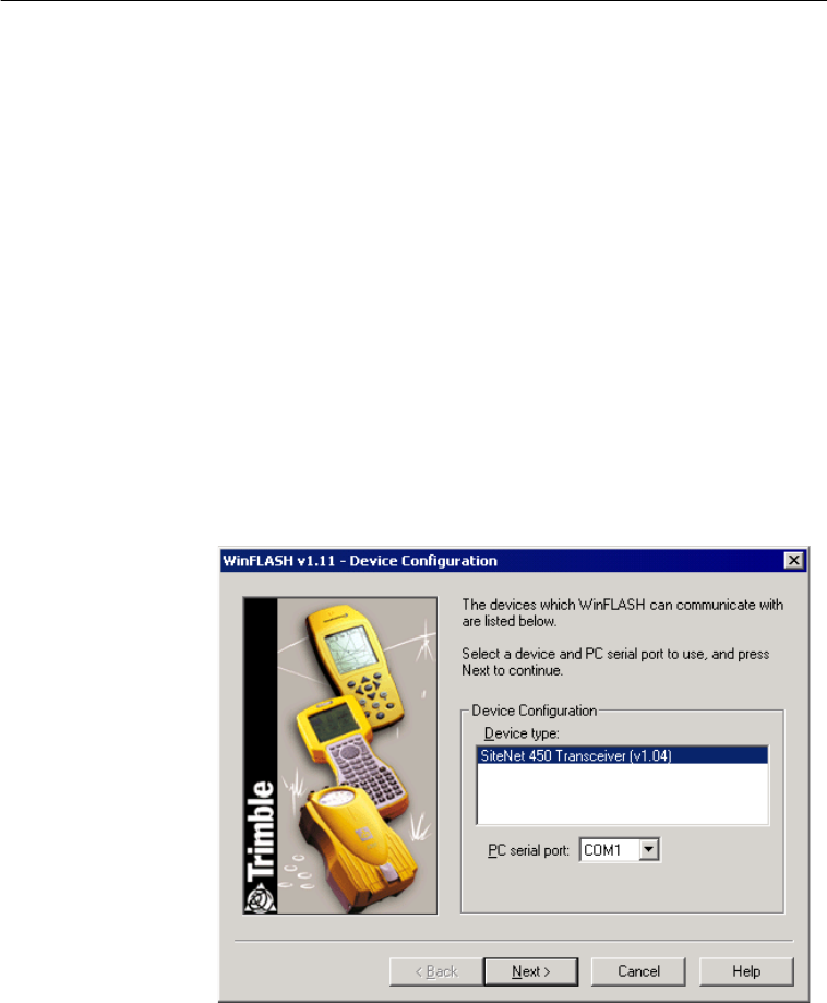
1. To start WinFLASH, click the WinFLASH icon. The
WinFLASH main window appears:
2. Follow the directions in the WinFLASH window to connect the
radio-modem to the PC.
SN450.book Page 7 Friday, October 5, 2001 5:01 PM
2 Configuring the SiteNet 450
8 SiteNet 450 Operation Manual
Note – WinFLASH is used to configure many different Trimble
products. If you have other Trimble products you may have to
make a selection in this window. Select the SiteNet 450
Transceiver (v1.04) option.
3. Select the appropriate PC serial port (COM port) and click
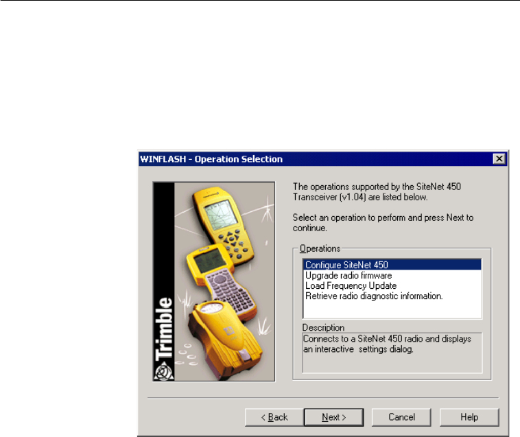
Next. The Operation Selection window appears.
SN450.book Page 8 Friday, October 5, 2001 5:01 PM
SiteNet 450 Operation Manual 9
Configuring the SiteNet 450 2
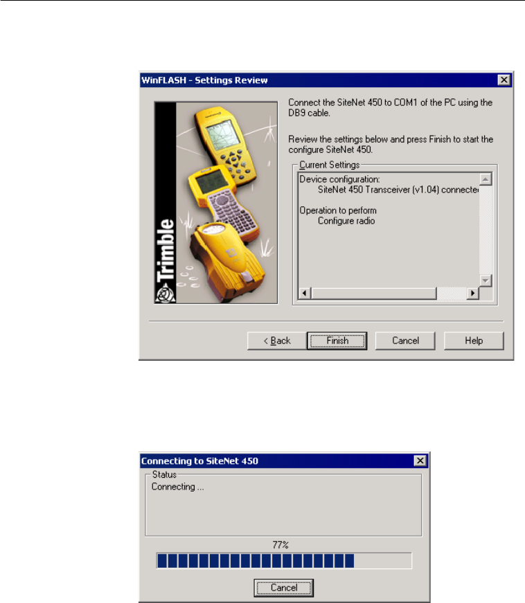
4. Select Configure SiteNet 450 and click Next. The
WinFLASH-Settings Review window appears:
5. Click Finish.
A connection status window appears, counts to 100%, and then
displays the SiteNet 450 configuration menu.
SN450.book Page 9 Friday, October 5, 2001 5:01 PM
2 Configuring the SiteNet 450
10 SiteNet 450 Operation Manual
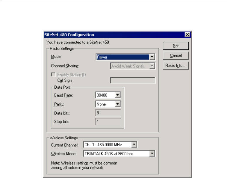
When a successful connection is established, the SiteNet 450
Configuration window replaces the WinFLASH window:
2.3.3
Configuring the SiteNet 450
To configure the SiteNet 450:
1. Select the appropriate operating Mode depending on intended
use, for example Rover.
2. Select the Channel Sharing configuration (base modes only, not
selectable for a repeater or rover). The options are:
–Off: The carrier detect mode is OFF. The SiteNet 450 will
ignore other transmissions on your frequency and continue
to transmit data.
SN450.book Page 10 Friday, October 5, 2001 5:01 PM

SiteNet 450 Operation Manual 11
Configuring the SiteNet 450 2
Note – Channel Sharing set to Off may be illegal in your
country-of-use. You may be subject to penalties or fines
based upon the specific licensing requirements for your
country-of-use. Please consult your radio license
documentation or licensing agency for operational
guidelines.
–Avoid Weak Signals: The carrier detect mode is ON. The
radio ceases to transmit if it detects another radio
transmission on its frequency. It resumes transmission
when the channel is free of radio traffic.
–Avoid Strong Signals: The carrier detect mode is ON, but
the radio stops transmitting only when there is a strong
signal present. (Receive level > –90 dBm.)
3. Select the Enable Station ID check box and enter your Call
Sign. This is a Federal Communications Commission
requirement for U.S. licensed users. It sets your radio to
transmit your Call Sign every 15 minutes in Morse Code.
4. In the Data Port field, set the Baud Rate and Parity. These are
the communications parameters between the receiver and radio.
Note – The default GPS port parameters for the SiteNet 450 are
38400 baud rate with parity none.
5. In the Wireless Settings field, select the appropriate Current
Channel option. This field determines the radio operating
frequency.
6. Select the Wireless Mode setting. This setting determines the
over-the-air communications parameters.
Note – These settings must be the same for all radios in the
same network.
SN450.book Page 11 Friday, October 5, 2001 5:01 PM
2 Configuring the SiteNet 450
12 SiteNet 450 Operation Manual
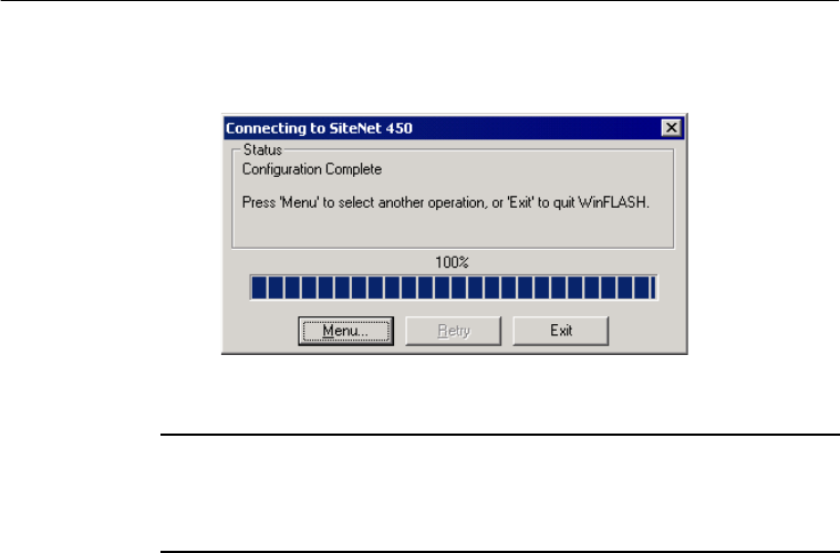
7. To update the configuration, click Set. The Connecting to
SiteNet 450 dialog appears:
8. You can return to the main menu, or exit WinFLASH.
BTip – Setting the wireless mode to the highest possible setting reduces
battery consumption on your base or repeater. For example, 9600 bps
consumes half the power of 4800 bps for the same data format and time
of operation.
SN450.book Page 12 Friday, October 5, 2001 5:01 PM
SiteNet 450 Operation Manual 13
Configuring the SiteNet 450 2
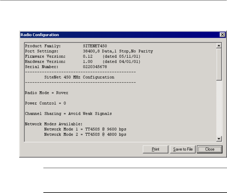
9. Click Radio Info to view a text listing of all radio information,
including its current configuration:
BTip – You can print or save to file the radio configuration information for
future reference or e-mail to your support provider to help with
troubleshooting radio problems.
2.3.4
Frequency List Updates
The SiteNet 450 can be programmed with a list of up to 20
frequencies, stored in nonvolatile memory. This list is preconfigured
based on the frequencies requested when the SiteNet 450 was ordered.
Governmental regulations require that only manufacturers or
authorized dealers can create this frequency list. All frequencies
programmed into a SiteNet 450 must comply with the host country
regulations.
SN450.book Page 13 Friday, October 5, 2001 5:01 PM

2 Configuring the SiteNet 450
14 SiteNet 450 Operation Manual
When you need to change the frequency list (add, delete, or replace
frequencies), contact your Trimble dealer and provide the
radio-modem’s serial number and an updated list of the frequencies
you require. Once you are provided with the frequency file, you may
upgrade the radio using the WinFLASH utility.
2.3.5
Software Updates
SiteNet 450 software upgrades are available at the Trimble World
Wide Web (www.trimble.com). Use the WinFLASH utility to upgrade
the SiteNet 450 software.
SN450.book Page 14 Friday, October 5, 2001 5:01 PM

CHAPTER
3
Installing the SiteNet 450
Network
3
In this chapter:
■Introduction
■Physical Description
■Mounting the SiteNet 450 on a Machine
■Cabling Configurations
■Antenna Description
SN450.book Page 15 Friday, October 5, 2001 5:01 PM

3 Installing the SiteNet 450 Network
16 SiteNet 450 Operation Manual
3.1
Introduction
Before setting up the equipment in the field, verify that each
radio-modem is set to the same channel and wireless data rate. Also
verify that the radio-modem’s Data Port settings are 38400 and parity
none. Set the serial port settings for both base and rover GPS receivers
to 38400 bps, 8 bits, parity none, and 1 stop bit. For more information
about general GPS receiver setup information, refer to the GPS
receiver manual. If these settings are not available, use the WinFLASH
utility to set the radio-modem’s serial port settings to those of the GPS
receiver.
Note – High-power signals from a nearby high-power radio station or
radar transmitter can overwhelm the radio-modem circuits. This does
not harm the instruments, but can prevent them from functioning
correctly. To avoid problems, try not to use the radio-modems within
400 meters (1300 feet) of powerful radar, television, or other
transmitters. Low-power transmitters such as those in portable phones
and walkie-talkies normally do not interfere with SiteNet 450
radio-modem operations unless they are tuned to the same channel.
Always monitor frequency before and during operation. Transmit only
on a clear channel.
Also, to avoid possible interference with GPS reception, keep the base
radio-modem antenna as far as possible from the GPS antenna. A
minimum of 3 meters (10 feet) is recommended.
For more information about the precautions when using certain
frequencies that can interfere with GPS operation, refer to Selecting
Communications Radios, page 47. This is a copy of Trimble’s
publication Using Radio Communication systems with GPS Surveying
Receivers (PN 1-612-0082-2/94).
Installation as a Repeater
To achieve coverage to all points in a survey area, a SiteNet 450
network may include up to two repeaters under certain conditions. The
repeaters retransmit data packets in a way that avoids interference
SN450.book Page 16 Friday, October 5, 2001 5:01 PM

SiteNet 450 Operation Manual 17
Installing the SiteNet 450 Network 3
with the base and each other. The operation of the repeaters is
transparent to the rovers. The rover will use the data packets from the
base or repeater, whichever it receives first.
The option to include a repeater in a network depends on the selected
wireless data rate and the broadcast information content. Table 3.1
illustrates when a repeater may be used in a network for various
wireless data rates, RTK formats, and RTK epoch rate.
3.2
Physical Description
The SiteNet 450 radio-modem is encased in a rugged, waterproof
metal case. It has an antenna mount on the top cap, and a connector
and LED on the bottom cap. The physical aspects of SiteNet 450
hardware are outlined below, followed by details covering interface
connections and antenna installations.
Table 3.1 Repeater use in networks
Wireless data
rate (bps) DGPS CMR
at 1 Hz RTCM 2.x at
1 Hz
4800 1 1 0
9600 2 2 1
2 - Two repeaters may be used
1 - One repeater may be used
0 - No repeaters may be used
SN450.book Page 17 Friday, October 5, 2001 5:01 PM
3 Installing the SiteNet 450 Network
18 SiteNet 450 Operation Manual
3.2.1
Connectors and Indicators
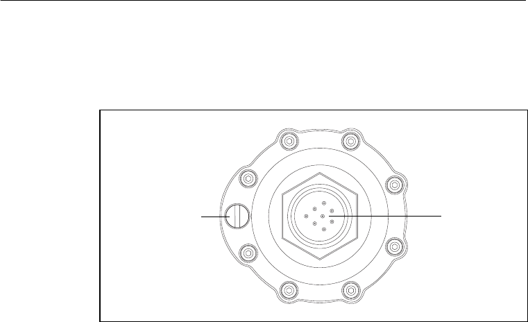
The SiteNet 450 bottom cap is fitted with an 8-pin male Bendix
connector and an LED indicator light. See Figure 3.1.
Figure 3.1 SiteNet 450 bottom cap
Power I/O
connector
(8-pin male
Bendix)
Data/Power
indicator LED
SN450.book Page 18 Friday, October 5, 2001 5:01 PM

SiteNet 450 Operation Manual 19
Installing the SiteNet 450 Network 3
The LED can be orange and/or green depending on the situation, as
shown in Table 3.2.
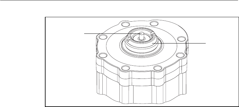
Note – The top cap of the SiteNet 450 has an antenna contact tip. The
tip is designed for maximum efficiency and very low loss. Please take
care not to damage this tip. Keep the low-profile antenna or flexible
antenna base screwed on to the top of the radio when storing the
SiteNet 450, see page 33.
Figure 3.2 shows the top cap.
Table 3.2 Operational status
LED Color Status
Orange (solid) Power is available.
Orange and green (both solid) Transmitting, receiving, or repeating.
VCO
Low battery
High temperature
Unknown error
Data overload
Very low battery
High temperature shutdown
No color Dead battery
SN450.book Page 19 Friday, October 5, 2001 5:01 PM
3 Installing the SiteNet 450 Network
20 SiteNet 450 Operation Manual
Figure 3.2 SiteNet 450 top cap
Contact tip Antenna
mount
SN450.book Page 20 Friday, October 5, 2001 5:01 PM

SiteNet 450 Operation Manual 21
Installing the SiteNet 450 Network 3
3.3
Mounting the SiteNet 450 on a Machine
When mounting the SiteNet 450 on a machine consider the following:
–Reduce damage by minimizing shock and vibration to the
SiteNet 450: Mount the radio-modem on a solid part of the
cab.
–Locate the best antenna position: Mount the entire antenna
above the roofline so that it has an uninterrupted view. This
improves the performance of the SiteNet 450.
–Prevent signal interference: Position the antenna away
from other antennas (particularly if the other antenna is a
two-way radio), rotating beacons and strobe lights.
Figure 3.4 shows a typical installation.
3.3.1
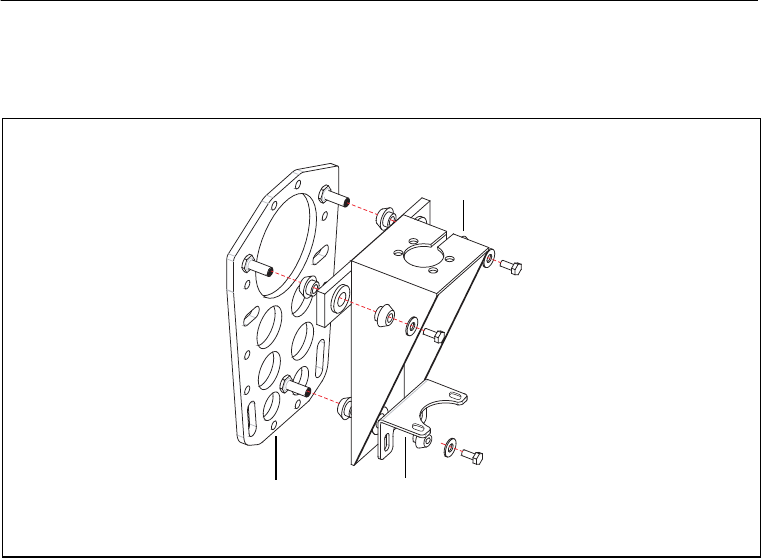
Machine Mount Kit (PN 35087-00)
The machine mounting kit for the SiteNet 450 comprises:
•Radio mount bracket (upper)
•Radio mount bracket (lower)
•Machine mount adapter plate (with U-bolts)
•Rubber shock mount kit
SN450.book Page 21 Friday, October 5, 2001 5:01 PM
3 Installing the SiteNet 450 Network
22 SiteNet 450 Operation Manual
Figure 3.3 shows the SiteNet 450 mounting kit and how the parts fit
together.
Figure 3.3 SiteNet 450 mounting kit
Mounting the SiteNet 450
To mount the SiteNet 450 onto a machine:
1. Bolt the SiteNet 450 into the radio mounting bracket (upper and
lower brackets).
Ensure that the radio mounting screws are all fitted with
washers and lock washers.
Radio mounting
bracket (upper)
PN 41530
Radio mounting
bracket (lower)
PN 41529
Adapter plate
PN 71105-00
SN450.book Page 22 Friday, October 5, 2001 5:01 PM

SiteNet 450 Operation Manual 23
Installing the SiteNet 450 Network 3
2. Securely mount the adapter plate to the machine. Do one of the
following:
–Use existing weld bosses (see Figure 3.4)
–Weld some weld bosses to the cab
–Clamp the plate to the top of a handrail at the top of the cab
using the U-bolts
3. Bolt the radio mounting bracket to the adapter plate using the
rubber shock mount kit. The bolts are included with the adapter
plate.
BTip – Use threadlocking Loctite (PN 33803) or equivalent to secure the
bolts when you assemble the shock mounts.
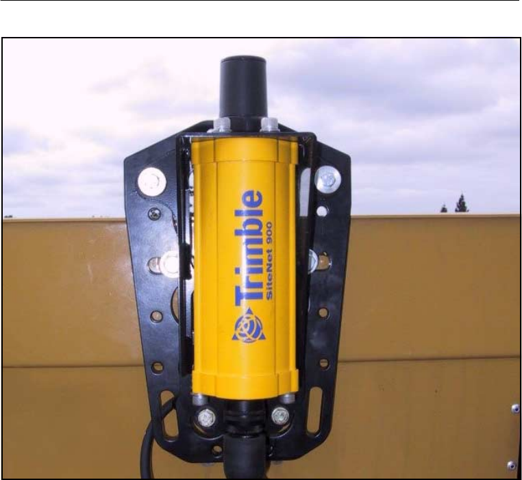
Figure 3.4 shows a SiteNet 450 mounted at the rear of a cab roof.
Notice how this installation ensures that all of the antenna is above the
cab’s roof.
****NEW PHOTO FROM Joan Hollerich GOES
HERE********THIS ONE SHOWS A 900*******
SN450.book Page 23 Friday, October 5, 2001 5:01 PM
3 Installing the SiteNet 450 Network
24 SiteNet 450 Operation Manual
Figure 3.4 SiteNet 450 mounted at the rear of a cab roof
SN450.book Page 24 Friday, October 5, 2001 5:01 PM

SiteNet 450 Operation Manual 25
Installing the SiteNet 450 Network 3
3.4
Cabling Configurations
The SiteNet 450 is typically configured as a rover, but the cables and
adapters necessary for other configurations are also available.
Table 3.3 summarizes the cabling items available or provided with the
SiteNet 450 unit or available accessories.
Table 3.3 SiteNet 450 cabling and power accessories
Item Part number
Power and I/O cable for machine installations, 5 m (17 ft)
8-pin female Bendix connector on each end 32942-17
Infrastructure/Base Station power and I/O cable, 7.5 m (25 ft)
8-pin female Bendix, with Y-split to TA-3 power connector,
DBF-9, plus 12-pin Conxall
38968-25
Machine service cable (21-pin female Bendix, with Y-split to
bare power leads and dual DBF-9 connector) 36938
DC power adapter cable with TA-3 connector and battery
clips 44087-00
SiteNet Base Station/Configuration cable, 30 m (99 ft) 40942-99
SN450.book Page 25 Friday, October 5, 2001 5:01 PM
3 Installing the SiteNet 450 Network
26 SiteNet 450 Operation Manual
3.4.1
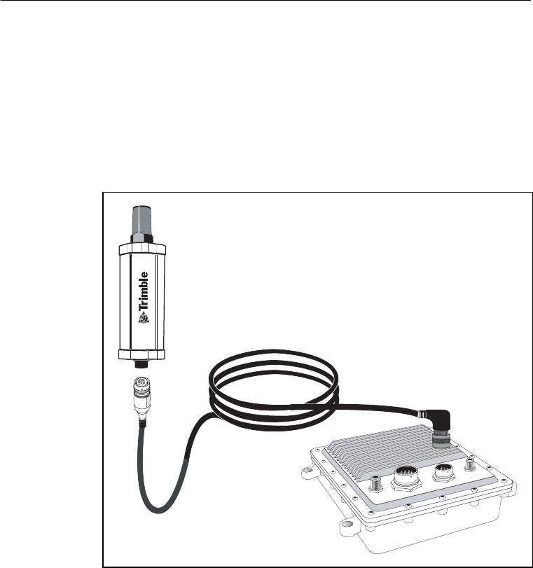
Power and I/O Cable for Machine Installations
The cable shown in Figure 3.5 connects the SiteNet 450 to either the
MS850™ or the MS860™ GPS receiver on the machine. The GPS
receiver outputs power to the SiteNet 450 through this cable.
The straight connector attaches to the bottom cap of the SiteNet 450,
and the angled connector attaches to the 8-pin Bendix connector of the
GPS receiver.
Figure 3.5 Power and I/O cable (PN 32942-17)
SN450.book Page 26 Friday, October 5, 2001 5:01 PM
SiteNet 450 Operation Manual 27
Installing the SiteNet 450 Network 3
3.4.2
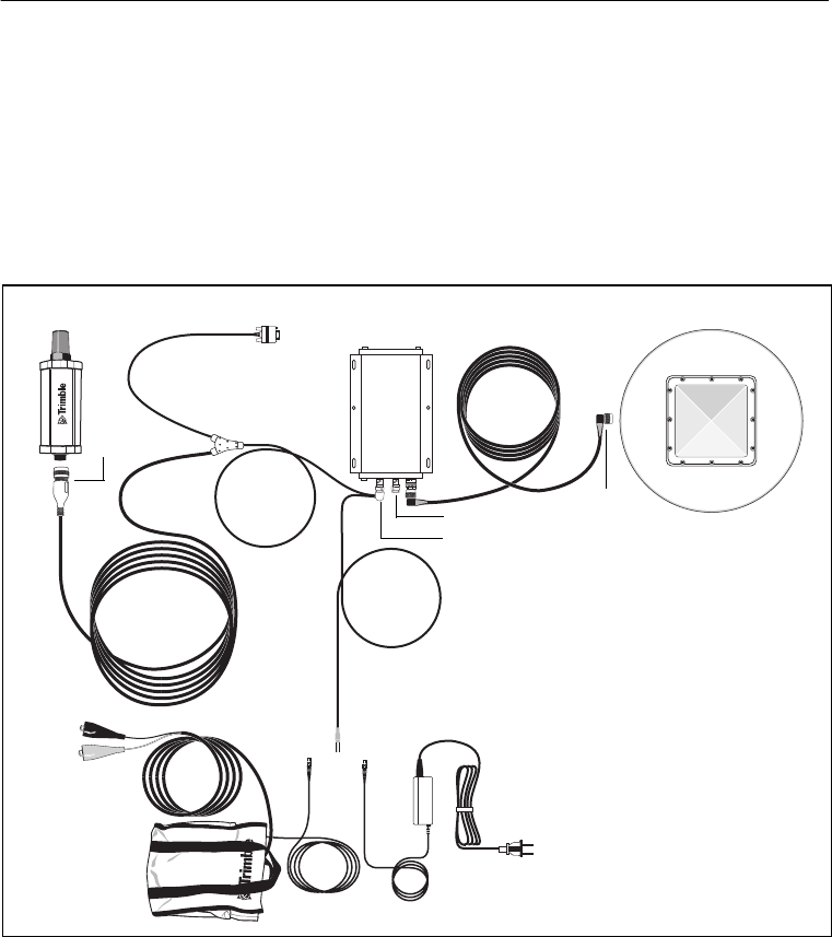
Infrastructure/Base Station Power and I/O Cable
The cable shown in Figure 3.6 is used for base station and repeater
installations of SiteNet 450s. Cables come in the lengths shown in
Table 3.4.
Table 3.4 Available cable lengths
Note – Nearly all installations of infrastructure radios will require
either a 7.5 m (25 ft) or a 30 m (99 ft) length.
Seal unused connectors by covering them with plastic tape.
Figure 3.6 Radio power and I/O cable (PN 38968-25)
Part number Cable length
38968-25 7.5 m (25 ft)
40942-03 1 m (3 ft)
40942-40 12 m (40 ft)
40942-99 30 m (99 ft)
8-pin Bendix to SiteNet 450
DB-9 to PC for data
or configuration
Conxall to
MS750
TA-3 power
SN450.book Page 27 Friday, October 5, 2001 5:01 PM
3 Installing the SiteNet 450 Network
28 SiteNet 450 Operation Manual
The 7.5 m (25 ft) infrastructure cable (PN 38968-25) connects directly
to the SiteNet 450. The 12-pin Conxall connector connects directly to
the MS750™ GPS receiver with a split to power via a TA-3 connector.
This cable also splits to a DBF-9, which can be used to configure the
SiteNet 450.
When you install this cable with a MS750 base station, the complete
cabling configuration looks similar to that shown in Figure 3.7.
Figure 3.7 MS750 base station using cable PN 38968-25
SiteNet 450 DB-9
Connect to
PC for radio
configuration
MS750 17515-xx
GPS antenna
AC power adapter
with TA-3 connector
38483
DC power
option
44087-00
8-pin
Bendix
Port B
Port A
N type
TA-3
TA-3
TA-3
38968-25
SN450.book Page 28 Friday, October 5, 2001 5:01 PM
SiteNet 450 Operation Manual 29
Installing the SiteNet 450 Network 3
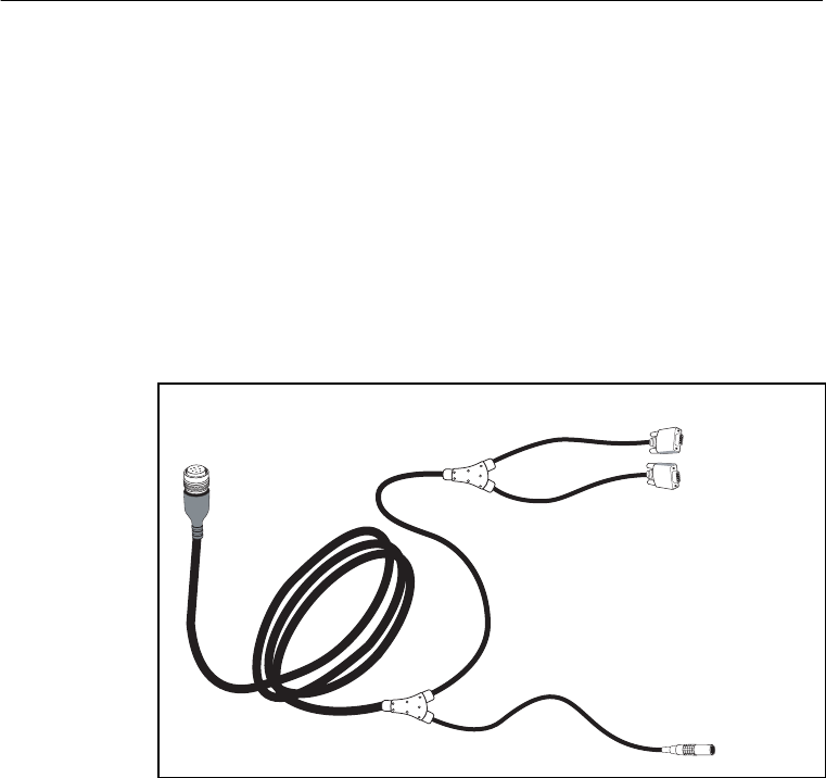
The 30 m (99 ft) infrastructure cable (PN 40942-99) connects directly
to the SiteNet 450 and splits out to power via a TA-3 connector and
communications via dual female DB-9 connectors. The DB-9
connectors can connect to a GPS receiver and to a PC at the same
time. This is particularly useful for troubleshooting. This cable
requires its own power for the radio. It has no Conxall connector for
the MS750 GPS receiver. You can connect it to the MS750 with the
hammerhead connector B1/B2 cable PN 37382 that comes with the
base (reference) station kit. The cable has a TA-3 connector for power
to the radio only. The MS750 must be powered separately with the
cables provided in the base station. See Figure 3.8.
Figure 3.8 Service cable assembly (PN 40942-03, -40, -99)
The 1 m (3 ft) cable (PN 40942-03) is designed for use with a survey
backpack.
1-shell 5-pin
Lemo power
DB-9 GPS
DB-9 I/O
8-pin Bendix
To SiteNet 450
To PC for
data or
configuration
To cable
PN 37382
SN450.book Page 29 Friday, October 5, 2001 5:01 PM
3 Installing the SiteNet 450 Network
30 SiteNet 450 Operation Manual
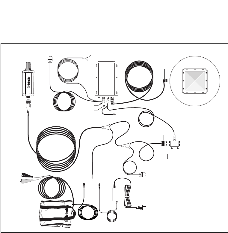
When you install cable 40942-xx with a MS750 base station, the
complete cabling configuration looks similar to that shown in
Figure 3.9.
Figure 3.9 MS750 base station using cable PN 40942-xx
38483
AC power adapter with
TA-3 connector
40942-xx
SiteNet 450
8-pin
DB-9
30945
MS750 17515-xx
GPS antenna
Data
B2 Data
A1/B1
Port A
Port B
DB-9 I/O
DC power
option
44087-00
Bendix
N-type
37382
DB-9 GPS
TA-3
TA-3 TA -3
SN450.book Page 30 Friday, October 5, 2001 5:01 PM
SiteNet 450 Operation Manual 31
Installing the SiteNet 450 Network 3
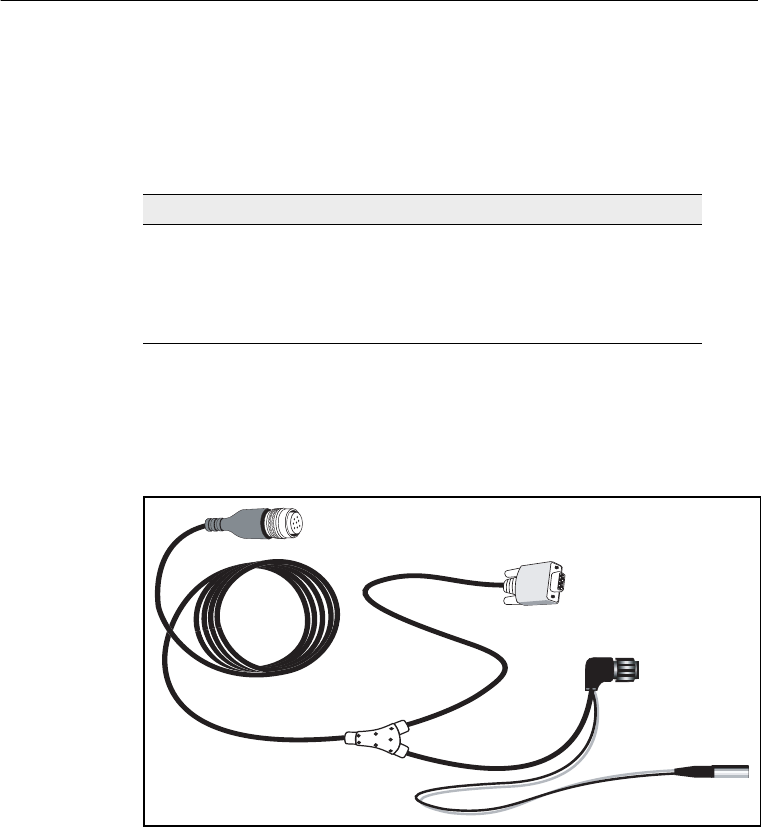
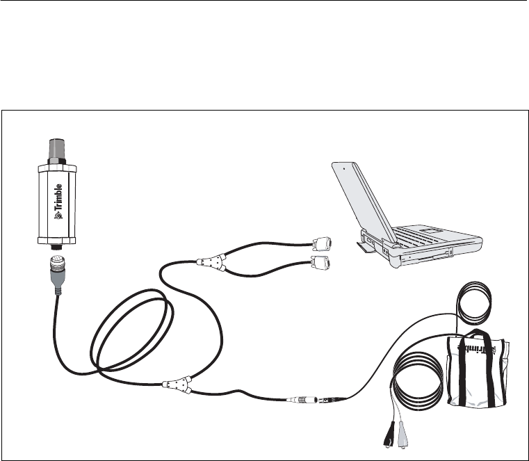
3.4.3
Machine Service Cable
Figure 3.10 shows cable 40942-xx when used to configure SiteNet 450
radios with a laptop.
Figure 3.10 Machine service cable (PN 40942-xx)
SiteNet 450
Cable
40942-40 (= 12 m or 40 ft)
40942-99 (= 30 m or 99 ft)
44086-00
8-pin
Bendix
DB-9 GPS
DB-9 I/O
1 shell
5-pin Lemo
DB-9 GPS
DB-9 I/O
SN450.book Page 31 Friday, October 5, 2001 5:01 PM
3 Installing the SiteNet 450 Network
32 SiteNet 450 Operation Manual
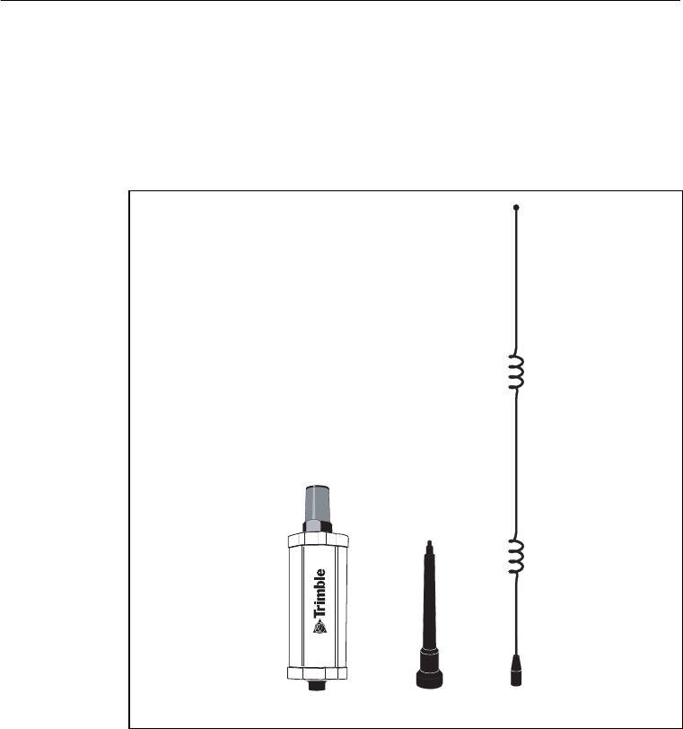
3.5
Antenna Description
The standard SiteNet 450 antenna is a 0 dB, low-profile antenna. An
optional infrastructure installation kit comes with an antenna base and
5 dB whip antenna tip. The 5 dB antenna measures 81 cm (32 in) in
length, including the base. See Figure 3.11.
Figure 3.11 SiteNet 450 with antennas
SiteNet 450 Antenna base 5 dB tip
0 dB low-profile antenna
SN450.book Page 32 Friday, October 5, 2001 5:01 PM

SiteNet 450 Operation Manual 33
Installing the SiteNet 450 Network 3
3.5.1
Antenna Considerations
Note – Please use care when removing the radio antenna. The
SiteNet 450 antenna contact tip is designed for maximum efficiency
and very low loss. To maintain its integrity, do not remove the top cap
from the radio housing.
Make sure that you mount the base and repeater radios as high as
possible. An increase in the antenna height increases your line of sight
and is the most effective way to increase the radio’s range. Consult
your license for the legal limits on antenna height.
Line-of-Sight Obstruction
Objects placed near the antennas, especially metal objects, can
severely limit antenna efficiency. If an antenna is to be mounted on a
mast, make sure it is mounted so that its radiating element is
completely above the top of any obstructing source, if possible.
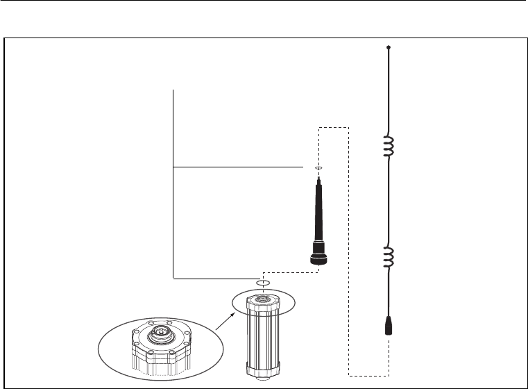
Figure 3.12 shows the optional infrastructure antenna mounting for
the SiteNet 450.
SN450.book Page 33 Friday, October 5, 2001 5:01 PM
3 Installing the SiteNet 450 Network
34 SiteNet 450 Operation Manual
Figure 3.12 Infrastructure antenna mounting
Antenna Length
The UHF whip antenna shipped with your system is factory tuned to
operate in the band you specified with your order (for example,
450–470 MHz). To ensure that your antenna is the correct length for
your frequency band, refer to Figure 3.13.
Top cap
O-ring
Flexible
antenna
base
5 dB tip
Make sure that you fit the O-rings
that are provided
O-ring
SN450.book Page 34 Friday, October 5, 2001 5:01 PM
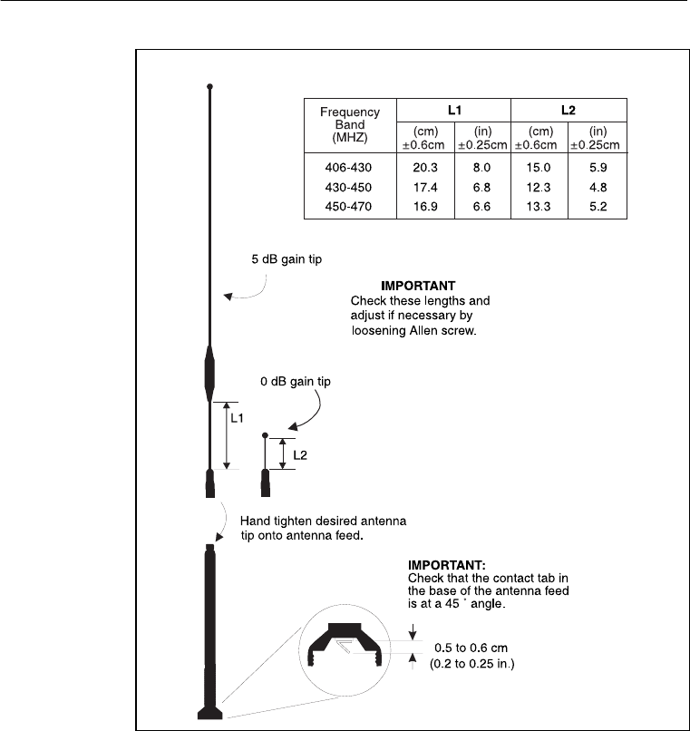
SiteNet 450 Operation Manual 35
Installing the SiteNet 450 Network 3
Figure 3.13 Standard UHF Omnidirectional Antennas
SN450.book Page 35 Friday, October 5, 2001 5:01 PM

3 Installing the SiteNet 450 Network
36 SiteNet 450 Operation Manual
SN450.book Page 36 Friday, October 5, 2001 5:01 PM

CHAPTER
4
Regulations and Safety
4
In this chapter:
■Introduction
■Type Approval
■Licensing
■Safety
SN450.book Page 37 Friday, October 5, 2001 5:01 PM

4 Regulations and Safety
38 SiteNet 450 Operation Manual
4.1
Introduction
Regulations regarding the use of the radio-modems vary greatly from
country to country. In some countries, the unit can be used without
obtaining an end-user license. Other countries require end-user
licensing. Consult your local communications governing agency for
licensing information.
Before operating a SiteNet 450 radio-modem, determine if
authorization or a license to operate the unit is required in your
country. It is the responsibility of the end user to obtain an operator’s
permit or license for the SiteNet 450 radio-modem for the location or
country of use.
Note – This device complies with Part 15 of the FCC Rules. Operation
is subject to the condition that this device does not cause harmful
interference.
4.2
Type Approval
CWarning – Changes or modifications to this equipment not approved in
writing by Trimble Navigation Limited voids your authority to operate the
equipment.
Type approval, or acceptance, covers technical parameters of the
equipment related to emissions that can cause interference. Type
approval is granted to the manufacturer of the transmission equipment,
independent from the operation or licensing of the units. Some
countries have unique technical requirements for operation in
particular radio-modem frequency bands. To comply with those
requirements, Trimble may have modified your equipment to be
granted Type approval. Unauthorized modification of the units voids
the Type approval, the warranty, and the operational license of the
equipment.
SN450.book Page 38 Friday, October 5, 2001 5:01 PM

SiteNet 450 Operation Manual 39
Regulations and Safety 4
4.3
Licensing
Many countries require that the operator of a radio or radio-modem
obtain a license prior to operating it. Consult your local
communications governing agency for licensing information.
Obtaining an operator’s permit or license for the SiteNet 450 for the
location or country of use is the responsibility of the end user.
Before operating this radio-modem, you are legally required to obtain
frequency licenses as required by the country of use. Please contact
your local communications governing agency for the licensing
requirements for each of these radio-modems.
4.4
Safety
Exposure to RF energy is an important safety consideration. The FCC
has adopted a safety standard for human exposure to radio frequency
electromagnetic energy emitted by FCC-regulated equipment as a
result of its actions in General Docket 79-144 on March 13, 1986.
Proper use of this radio-modem results in exposure below government
limits. The following precautions are recommended:
•Do not operate the transmitter when someone is within
0.6 meter (2 ft) of the antenna.
•Do not operate the transmitter unless all RF connectors are
secure and any open connectors are properly terminated.
•Do not operate the equipment near electrical blasting caps or in
an explosive atmosphere.
•All equipment must be properly grounded according to Trimble
installation instructions for safe operation.
•All equipment should be serviced only by a qualified
technician.
SN450.book Page 39 Friday, October 5, 2001 5:01 PM

4 Regulations and Safety
40 SiteNet 450 Operation Manual
SN450.book Page 40 Friday, October 5, 2001 5:01 PM

APPENDIX
A
Technical Specifications
A
In this appendix:
■Technical information
■Pinout information
SN450.book Page 41 Friday, October 5, 2001 5:01 PM

A Technical Specifications
42 SiteNet 450 Operation Manual
A.1 Technical Information
The table shows the technical information for the SiteNet 450
radio-modem. This information is subject to change without notice.
Table A.1 Technical information
Specification
Physical:
Size
Weight
85 mm (3.4") W x 270 mm (10.5") H plus
antenna height
0.9 kg (2.0 lb)
Environmental:
Operating temperature
Storage temperature
Humidity
Vibration
–40° to +65°C
–40° to +85°C
Exceeds MIL-STD-810E (aggravated cyclic
humidity), sealed to ±34.5 kPa (±5 psi),
immersible to 1 m
8gRMS, 20–2000 Hz random vibration
Shock:
Operational
Survival ±40 g, 10 msec
±75 g, 6 msec
Electrical
Power consumption:
Nominal
Transmit
Protection
Input range
250 mA (3W)1
1000 mA (12 W)1
Reverse polarity
10.5 VDC to 20 VDC unconditioned
SN450.book Page 42 Friday, October 5, 2001 5:01 PM

SiteNet 450 Operation Manual 43
Technical Specifications A
1 Power consumption, as well as the permissible number of repeaters in a network, depends on the selected
wireless data rate and the broadcast information content and rate (that is, CMR vs. RTCM SC-104 Ver. 2.1
packets at 1 Hz). The 9600 bps wireless data rate is not available for units with 12.5 kHz channel spacing.
2 Broadcast frequency, transmit power, channel spacing, and antenna gain are regulated by countries-of-use.
These are unique on a per-country basis. The broadcast frequencies, channel spacing, and country-of-use
for the radio-modem must be specified at time of order. Contact you local Trimble representative for more
information.
Connector:
Type
Provides
Indicators
8-pin male Bendix
Power, 2 serial ports, CAN interface
Power and data LED
Radio-modem performance
Range:
Optimal
Typical 10 km (6 miles), line-of-sight
3–5km (2–3 miles)
Varies with terrain and operating conditions.
A repeater may be used to extend the range.
Radio link:
Frequency range
Channel spacing
Transmit power
Channels
Wireless data rates
Modes
Single 10 MHz band per unit
430–440 MHz, 440–450 MHz,
450–460 MHz, or 460–470 MHz
12.5 kHz or 25 kHz (only 440–450 MHz is
available in 12.5 kHz at this time)
0.5 W
Up to 20 (factory pre-set)2
12.5 kHz channel, 4800, 8000 bps
25 kHz channel, 4800, 8000, 9600 bps
Base/Repeater/Rover
Table A.1 Technical information (continued)
Specification
SN450.book Page 43 Friday, October 5, 2001 5:01 PM
A Technical Specifications
44 SiteNet 450 Operation Manual
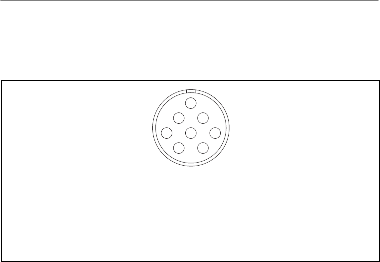
A.2 Pinout Information
Figure A.1 shows the pinout information for the 8-pin male Bendix
connector on the base of the SiteNet 450 radio-modem.
Figure A.1 SiteNet 450 connector (8-pin Mil-Spec)
Pin Function
A Power to radio
BGND
C RS-232 TXD2
D RS-232 RXD2
Pin Function
ECAN Hi
F RS-232 TXD3
G RS-232 RXD3
HCAN Lo
AB
C
D
E
F
G
H
SN450.book Page 44 Friday, October 5, 2001 5:01 PM

APPENDIX
B
Using Radios with GPS
B
In this appendix:
■Introduction
■Selecting Communications Radios
■Useful Field Procedures
■Summary
SN450.book Page 45 Friday, October 5, 2001 5:01 PM

B Using Radios with GPS
46 SiteNet 450 Operation Manual
B.1 Introduction
Note – For more information, refer to the Trimble publication “Using
Radio Communication Systems with GPS Surveying Receivers”
(PN 1-612-0082-2/94).
“GPS receiver, antenna, tripod, tribrach, tape, cones, flagging,
radio...”, such is the checklist of most GPS surveyors preparing for a
day of observations. But a truly successful survey is not just a matter
of making sure that you have all of the equipment; you must also
ensure that you optimize the usage of these new tools for the highest
productivity.
The GPS receiver is trying to measure very faint radio signals from
satellites orbiting at 22,000 kilometers in space. There are many
factors that can hinder the receiver’s ability to perform. For example,
placing your hand over the antenna or setting up the antenna under a
tree are factors that have already proven to interfere with GPS signal
reception.
As GPS receivers developed, their processors have become more
sensitive to incoming data flow. This provides an increase in accuracy
by extracting more information out of the GPS radio signal. But with
this gain in accuracy, there is an increased susceptibility to other radio
signals. The receiver is now more sensitive to the incoming GPS
signal, and consequently it is also more sensitive to other incoming
radio signals. This means that communications radios, such as those
commonly used by surveyors, can sometimes create difficulty with the
GPS signal reception.
There are some very simple steps you can follow to remove the effects
of radio interference on the GPS receiver. First, you should be aware
of the type of communications equipment you buy and understand its
characteristics. Secondly, a little care in using communications radios
can greatly decrease your chances of experiencing any interference
with satellite tracking.
SN450.book Page 46 Friday, October 5, 2001 5:01 PM

SiteNet 450 Operation Manual 47
Using Radios with GPS B
B.2 Selecting Communications Radios
If you do not already have communications radios, and are thinking of
buying them to supplement your survey activities, there are a number
of factors to keep in mind before purchasing:
•Some frequencies can cause interruptions of GPS tracking.
•Some communications equipment creates spurious signals not
related to their frequency that can interfere with satellite
tracking.
•Powerful communications transmitters can create such a strong
radio signal that the GPS signal cannot be identified.
Most communication transmitters emit overtones of their assigned
frequency. If these overtones line up with the GPS frequency, they can
filter into the GPS equipment and interfere with the satellite tracking.
Some communication transmitters emit more of these overtones than
others. But the number of overtones can be difficult to determine and
it is not the most important factor when considering this nuisance
parameter. To avoid being effected by transmitter overtones, avoid
those frequencies that lie within the GPS frequency range.
SN450.book Page 47 Friday, October 5, 2001 5:01 PM

B Using Radios with GPS
48 SiteNet 450 Operation Manual
Table B.1 shows frequency bands that you should avoid when using
GPS surveying receivers.
Table B.1 RF bands to avoid
From this frequency To this frequency
781.210 794.210
607.300 620.300
520.806 529.473
404.866 413.533
390.605 397.105
312.484 317.684
303.650 310.150
260.403 264.736
242.920 248.120
223.202 226.917
202.433 206.766
195.302 198.552
173.602 177.228
156.242 158.842
151.825 155.075
142.038 144.401
134.955 137.844
130.201 132.368
120.186 124.060
110.418 113.458
SN450.book Page 48 Friday, October 5, 2001 5:01 PM

SiteNet 450 Operation Manual 49
Using Radios with GPS B
Some communication transmitters and receivers also emit spurious
signals. These are extremely difficult to predict. The only way to know
if your receiver is being effected by spuriously emitted signals is to
test the communication equipment with the GPS receiver. If you plan
to buy a new radio, test it with your existing GPS equipment to
determine if any problems exist.
Communications equipment that uses more power is more likely to
create signals from which the GPS signal cannot be extracted. This
typically occurs from signals emitted from the radio transmitter box
and not its antenna. Non-GPS signals enter the GPS system through
the GPS antenna and not through the receiver. Therefore, most of the
effects of non-GPS signals can be minimized by physically separating
your radio and GPS equipment.
B.3 Useful Field Procedures
There are a few useful field procedures you can follow to minimize
the effects of your radio. Since most of the radio signal in the GPS
band is emitted directly from the radio transmitter box and received
via the GPS antenna, make sure the GPS antenna is separated from the
radio transmitter by 2-3 meters (7-10 feet). If you are still
experiencing difficulties at this distance, the GPS signal may be
getting overpowered by the radio transmissions. In this case, you can
either separate the equipment even more or shield the radio
transmitter.
As you move farther away from the source of the transmission, radio
signal strength drops as a square of the distance. Therefore, if there is
a problem, separate the GPS antenna and radio even more to lessen the
strength of the radio signal received at the GPS antenna.
If you are using a geodetic antenna, you can use the antenna’s ground
plane to shield the radio waves. In fact, you can shield the antenna
from the radio signal by moving behind nearby objects such as a car or
tree. If you cannot move away from the GPS antenna, move the radio
below the level of the GPS antenna ground plane. This is not ideal, but
may help in those cases where you are left with no alternative.
SN450.book Page 49 Friday, October 5, 2001 5:01 PM

B Using Radios with GPS
50 SiteNet 450 Operation Manual
B.4 Summary
Using communications radios with GPS receivers requires some
special considerations. By striving to extract the utmost accuracy from
the GPS system, receiver designs have made greater use of the radio
spectrum. However, the methods used to increase performance and
accuracy also make GPS receivers more susceptible to receiving other
radio signals.
Radio signals in the GPS band arise from a few different sources.
Some radio transmitters produce overtones of their frequency, which
lie within the GPS P-code frequency range. Others create random,
spurious signals, which affect GPS signal reception. Still other radio
systems use high power levels to boost communication range and
create noise that limits the GPS signal tracking. These are all
characteristics to avoid when purchasing or using communications
equipment in conjunction with GPS.
Before using radios on a full-fledged survey job, it is a good idea to
test the communications equipment to determine if it effects the GPS
signal reception in any way. Testing radios with the GPS equipment is
especially important if you are considering purchasing new radios.
Make sure to always:
•choose the communication frequency of your radios carefully
so they do not transmit on or create harmonics in the frequency
range of GPS.
•test them with your GPS receivers.
•if problems arise, put some distance between the radio
transmitter case and the GPS antenna. Also, shielding the radio
transmitter should minimize the effects of radio signals on the
GPS signal reception.
Radio signal strength drops as a function of distance. The greater the
separation between the GPS antenna and the radio transmitter, the less
likely you are to experience interruptions in satellite tracking.
SN450.book Page 50 Friday, October 5, 2001 5:01 PM
SiteNet 450 Operation Manual 51
Index
Numerics
8-pin Bendix connector 44
A
antenna
contact tip 19
description of 32
location of 17, 34
B
base station, installations 27
base/repeater 6
C
cables
configurations available 25
infrastructure power 27
machine installations 26
machine service 7, 31
SiteNet 450 configurations 25
troubleshooting for 29
cap bottom 44
top 19, 33
CMR, format 2
communications radios 47
connectors and indicators 18, 43
Bendix 25, 44
infrastructure cable 29
pinout 44
power and I/O cable 26
D
data modem 6
data, raw GPS 2
E
electrical specification 42
environmental specification 42
F
field procedures 49
frequency
band 4
bands to avoid 48
range 43
G
green LED 19
SN450.book Page 51 Friday, October 5, 2001 5:01 PM

Index
52 SiteNet 450 Operation Manual
H
hardware, performance 2
humidity, specification 42
I
indicator, LED 19
installing. See mounting the SiteNet 450
L
LED indicator light 19
licensing 39
M
machine mounting 21, 22
modem, description 17
mounting the SiteNet 450
antenna, considerations 33
machine 21, 22
O
operating temperature 42
orange LED 19
P
performance, specification 43
power 19
accessories 25
cables 26
consumption 42
I/O cable 26
infrastructure/base station 27
requirements 2
R
radios, communications 47
range, specification 43
regulations 37
release notes viii
RF energy 39
S
safety 37
setup 6
shock, specification 42
SiteNet 450
additional options to 3
base/repeater configuration 6
connecting to 7
features of 3
options of 3
size 42
specifications, technical 42
storage temperature 42
SN450.book Page 52 Friday, October 5, 2001 5:01 PM


Index
54 SiteNet 450 Operation Manual
SN450.book Page 54 Friday, October 5, 2001 5:01 PM

Reader Comment Form
SiteNet 450 Operation Manual October 2001
PN 45423-00-ENG Revision A
We appreciate your comments and suggestions for improving this publication.
Which Trimble product do you use? _____________________________________________
What do you use your Trimble product for? _______________________________________
__________________________________________________________________________
Please circle a response for each of the statements below:
Please answer the following questions:
Which sections do you use the most? ____________________________________________
What do you like best about the manual? _________________________________________
__________________________________________________________________________
What do you like least about the manual? _________________________________________
__________________________________________________________________________
Optional:
Name _____________________________________________________________________
Company __________________________________________________________________
Address____________________________________________________________________
__________________________________________________________________________
Telephone ____________________________Fax____________________________________
Please mail to the local office listed on the back cover or to Trimble Navigation Limited,
Engineering and Construction, 5475 Kellenburger Road, Dayton, Ohio 45424-1099, U.S.A.
Alternatively, e-mail your comments and suggestions to ReaderFeedback@trimble.com. All
comments and suggestions become the property of Trimble Navigation Limited.
1 = strongly agree 2 = agree 3 = neutral 4 = disagree 5 = strongly disagree
The manual is well organized. 1 2 3 4 5
I can find the information I want. 1 2 3 4 5
The information in the manual is accurate. 1 2 3 4 5
I can easily understand the instructions. 1 2 3 4 5
The manual contains enough examples. 1 2 3 4 5
The examples are appropriate and helpful. 1 2 3 4 5
The layout and format are attractive and useful. 1 2 3 4 5
The illustrations are clear and helpful. 1 2 3 4 5
The manual is: too long just right too short
SN450.book Page 55 Friday, October 5, 2001 5:01 PM
SN450.book Page 56 Friday, October 5, 2001 5:01 PM