Trimble 45145-5800 GPS Receiver with Bluetooth User Manual 5700 5800 GPS Receiver User Guide
Trimble Navigation Ltd GPS Receiver with Bluetooth 5700 5800 GPS Receiver User Guide
UserManual.wiki
>
Trimble
>
45145 5800 User Manual
manual
Navigation menu
Upload a User Manual
Namespaces
Wiki Guide
HTML
PDF
Info
Views
User Manual
Discussion / Help
Navigation

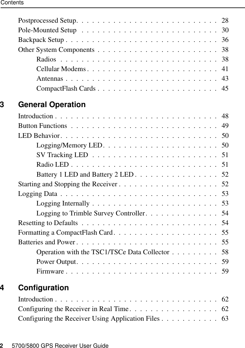
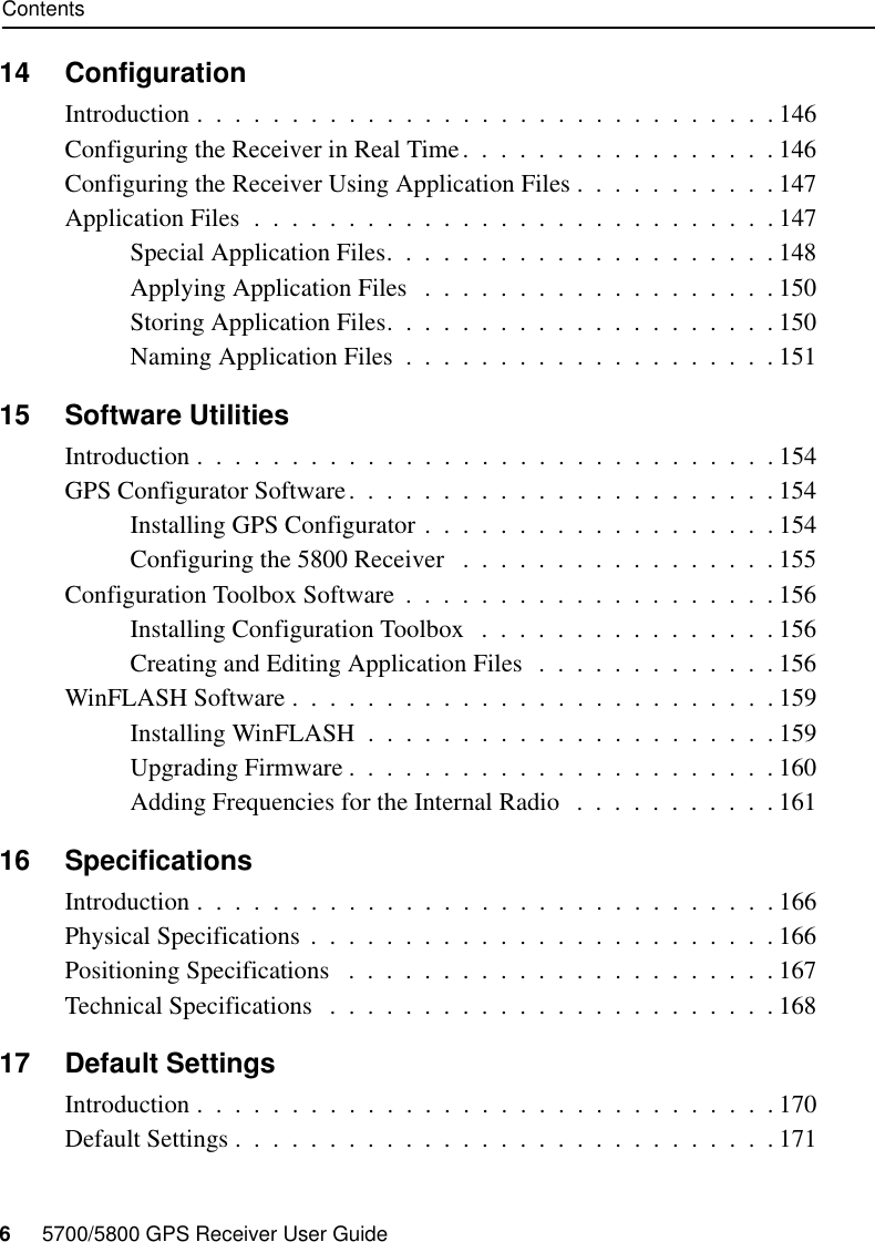

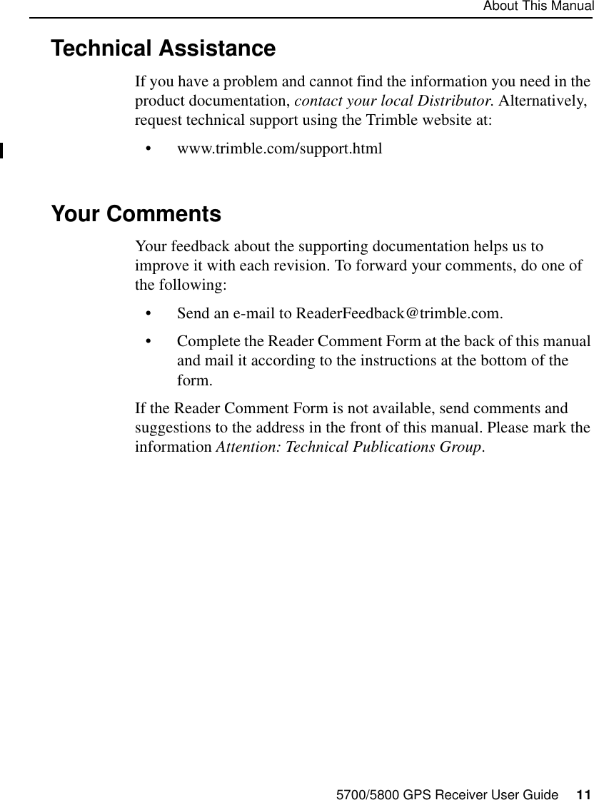


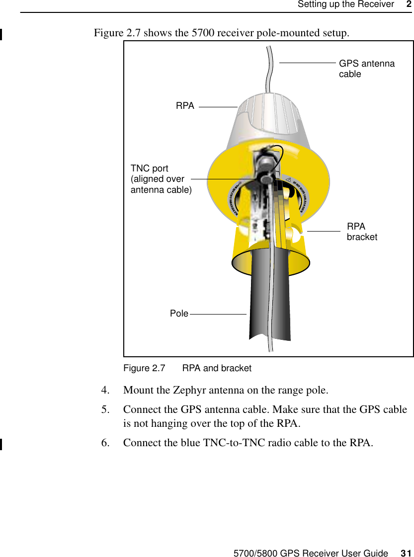
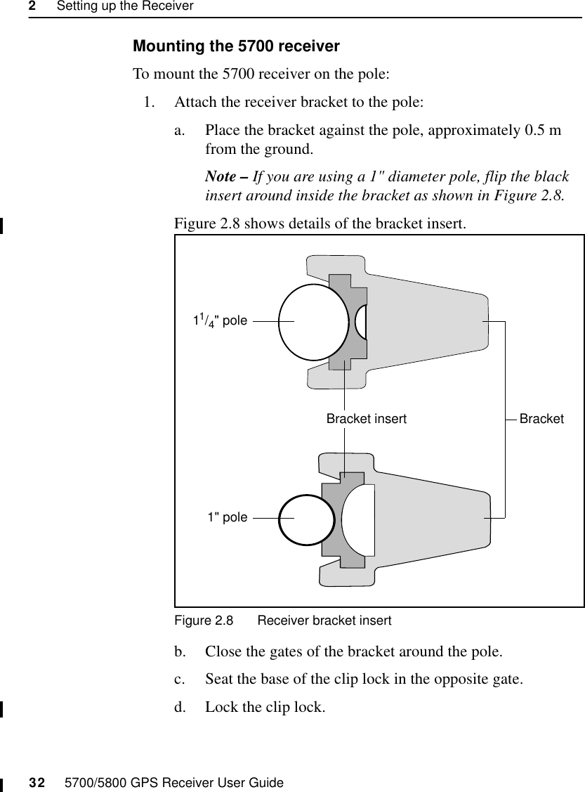
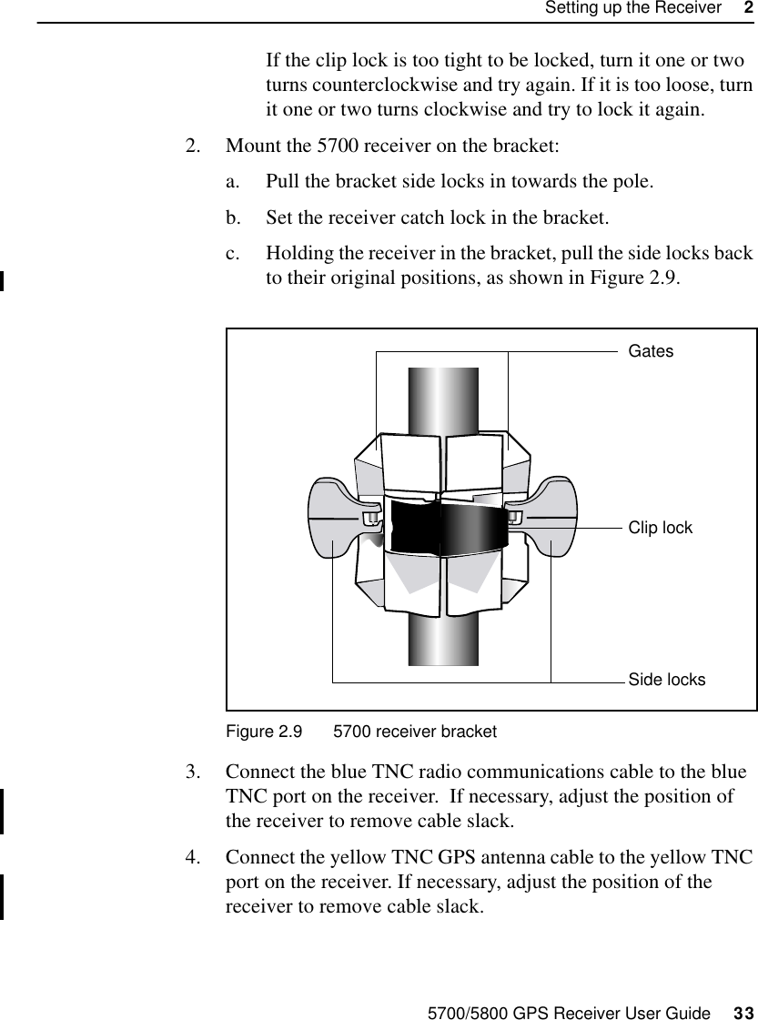

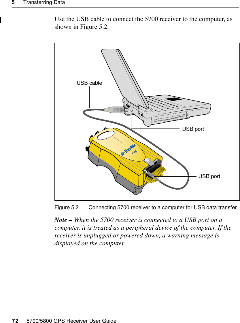
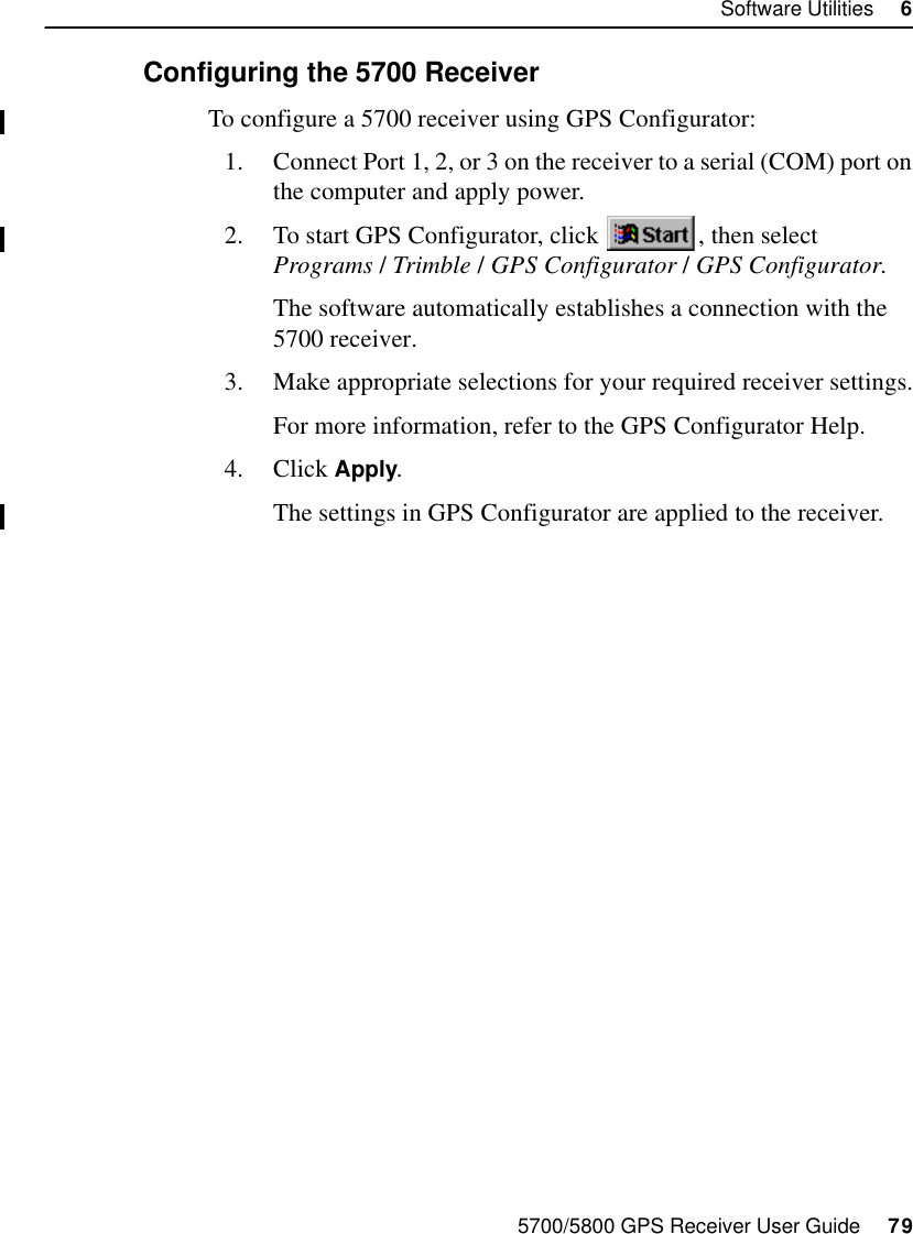

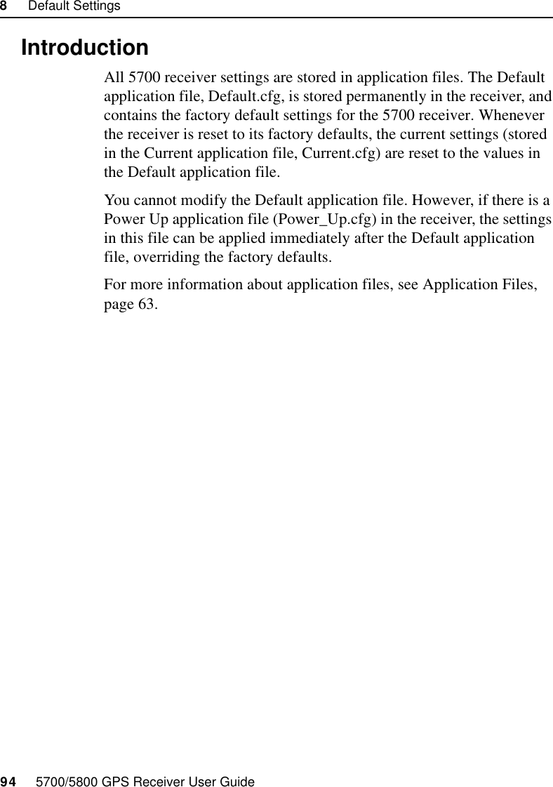
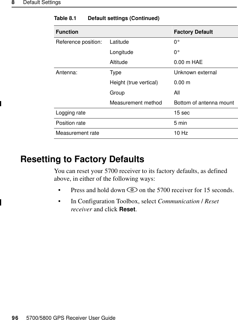
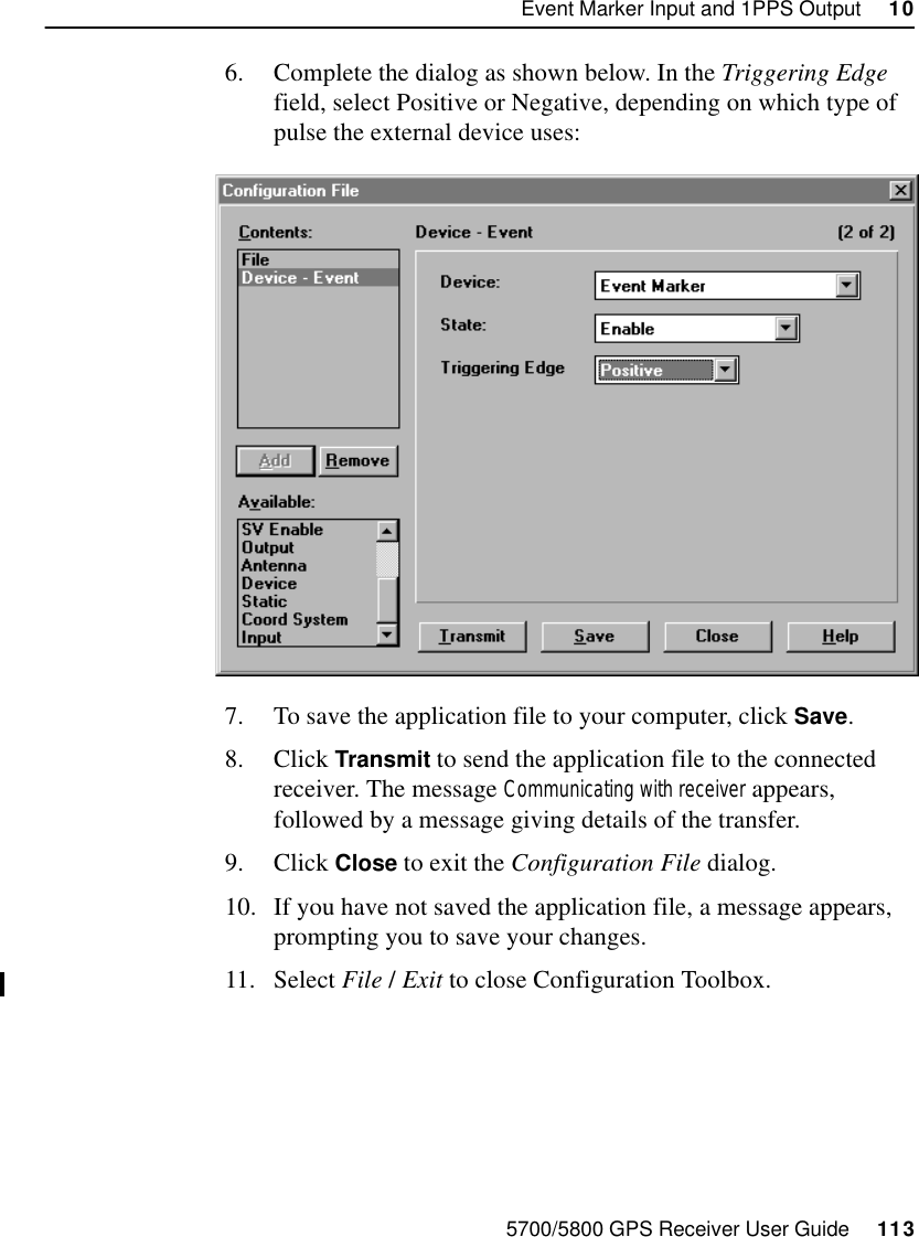
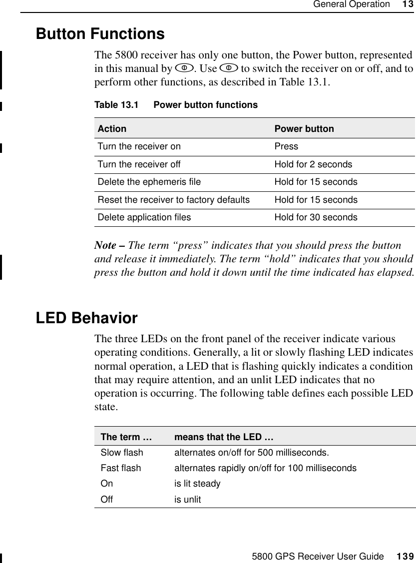
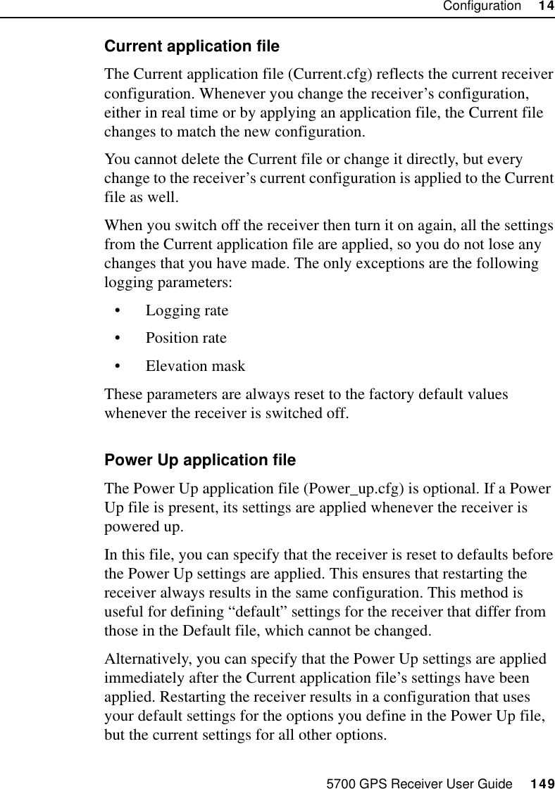
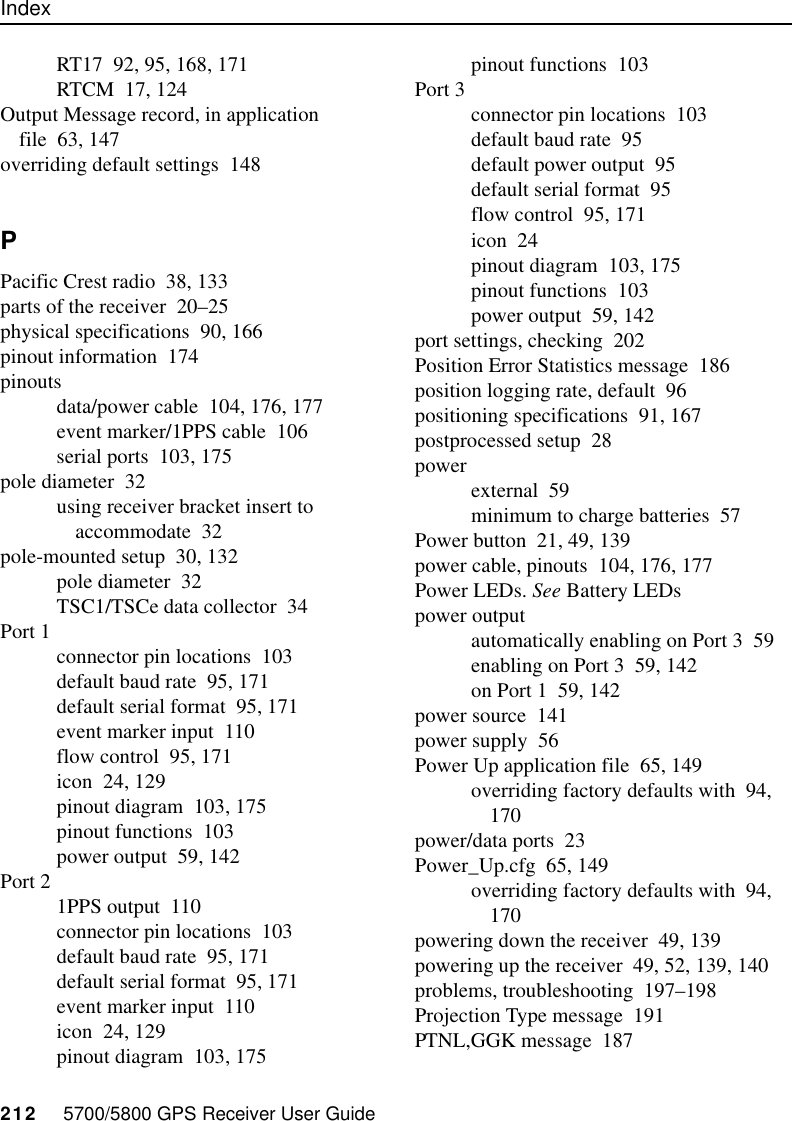
![5700/5800 GPS Receiver User Guide 95Default Settings 855700 Reference8.2 Default SettingsTable 8.1 defines the default settings for the 5700 receiver, as defined in the Default application file:Table 8.1 Default settingsFunction Factory DefaultSV Enable All SVs enabledGeneral Controls: Elevation mask 13°SNR mask 7RTK positioning mode Low LatencyMotion KinematicPower Output 3 Disabled1PPS time tags OffASCII time tags OffSerial Port 1: Baud rate 38400Format 8-None-1Flow control NoneSerial Port 2: Baud rate 38400Format 8-None-1Serial Port 3: Baud rate 38400Format 8-None-1Flow control NoneInput Setup: Station AnyNMEA/ASCII (all messages) All Ports OffStreamed output All Types OffOffset = 00RT17/Binary All Ports OffCMR output [Static] CMR: cref ID 0000RTCM output RTCM: Type 1 ID 0000](https://usermanual.wiki/Trimble/45145-5800/User-Guide-270156-Page-99.png)