Trimble 6248192-B1 GPS Rx with BT and 900 MHz FHSS Tx User Manual SPSx80 Smart GPS Antenna User Guide
Trimble Navigation Ltd GPS Rx with BT and 900 MHz FHSS Tx SPSx80 Smart GPS Antenna User Guide
UserManual.wiki
>
Trimble
>
6248192 B1 User Manual
User Manual
Navigation menu
Upload a User Manual
Namespaces
Wiki Guide
HTML
PDF
Info
Views
User Manual
Discussion / Help
Navigation

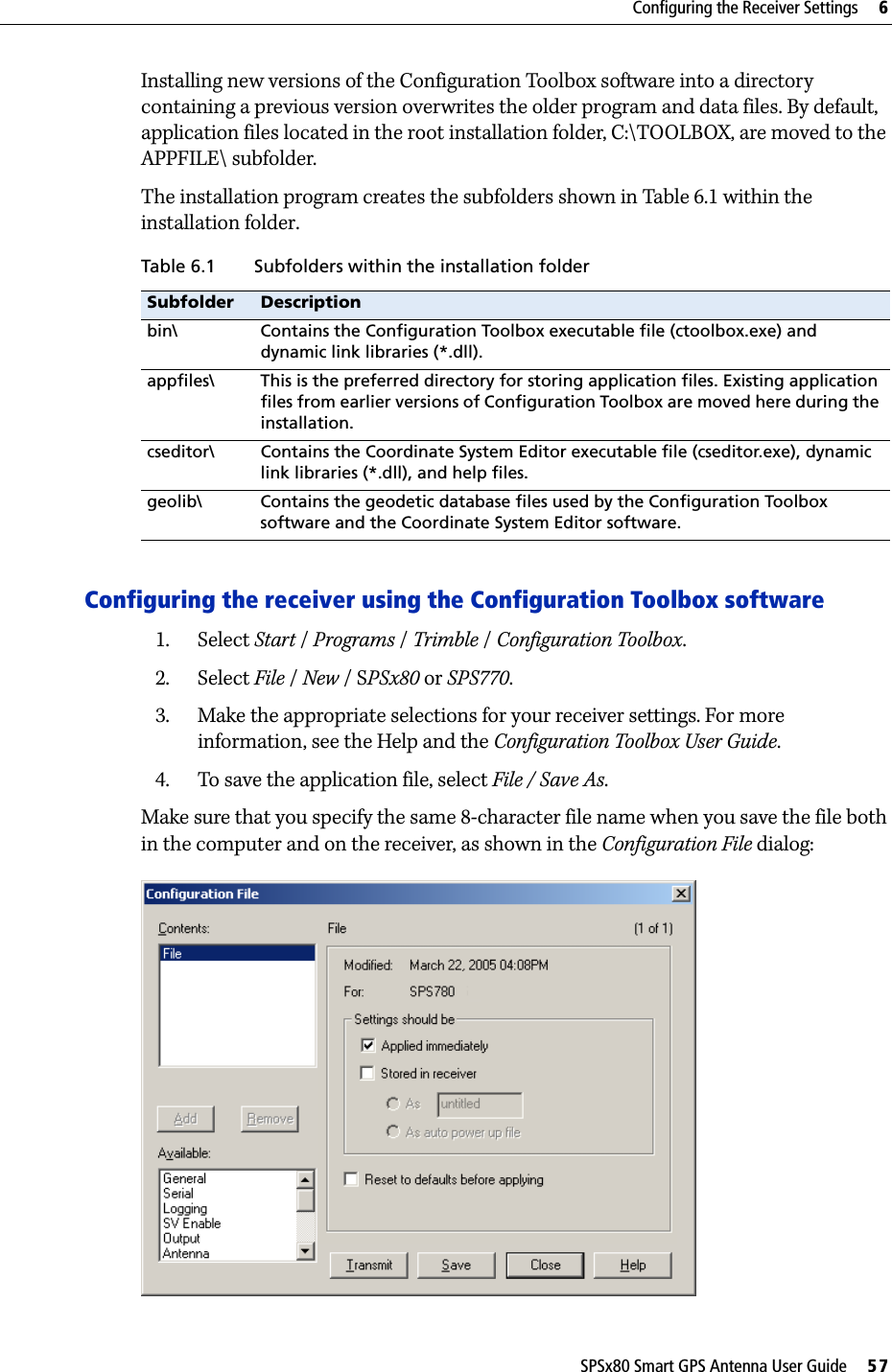
![1 Introduction14 SPSx80 Smart GPS Antenna User GuideRelated InformationSources of related information include the following:•Help – The SCS900 Site Controller software has built-in, context-sensitive help that lets you quickly find the information you need. Access it from the Help menu. Alternatively, click the ? button in a dialog, or press [F1]. On a Microsoft® Windows® CE device, select Start / Help.•Release notes – The release notes describe new features of the product, information not included in the manuals, and any changes to the manuals. They are provided as a .pdf file on the Trimble SPS GPS Receiver CD. •Trimble training courses – Consider a training course to help you use your GPS system to its fullest potential. For more information, go to the Trimble website at www.trimble.com/training.html.Technical SupportIf you have a problem and cannot find the information you need in the product documentation, contact your local dealer. Alternatively, go to the Support area of the Trimble website (www.trimble.com/support.shtml). Select the product you need information on. Product updates, documentation, and any support issues are available for download.If you need to contact Trimble technical support, complete the online inquiry form at www.trimble.com/support_form.asp. Your CommentsYour feedback about the supporting documentation helps us to improve it with each revision. E-mail your comments to ReaderFeedback@trimble.com.](https://usermanual.wiki/Trimble/6248192-B1/User-Guide-882580-Page-14.png)


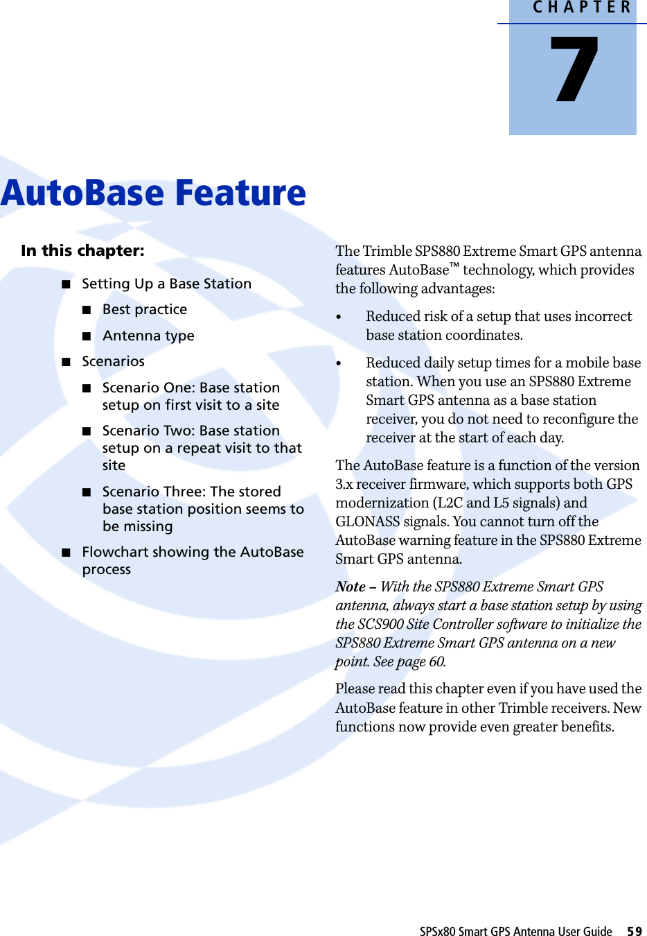


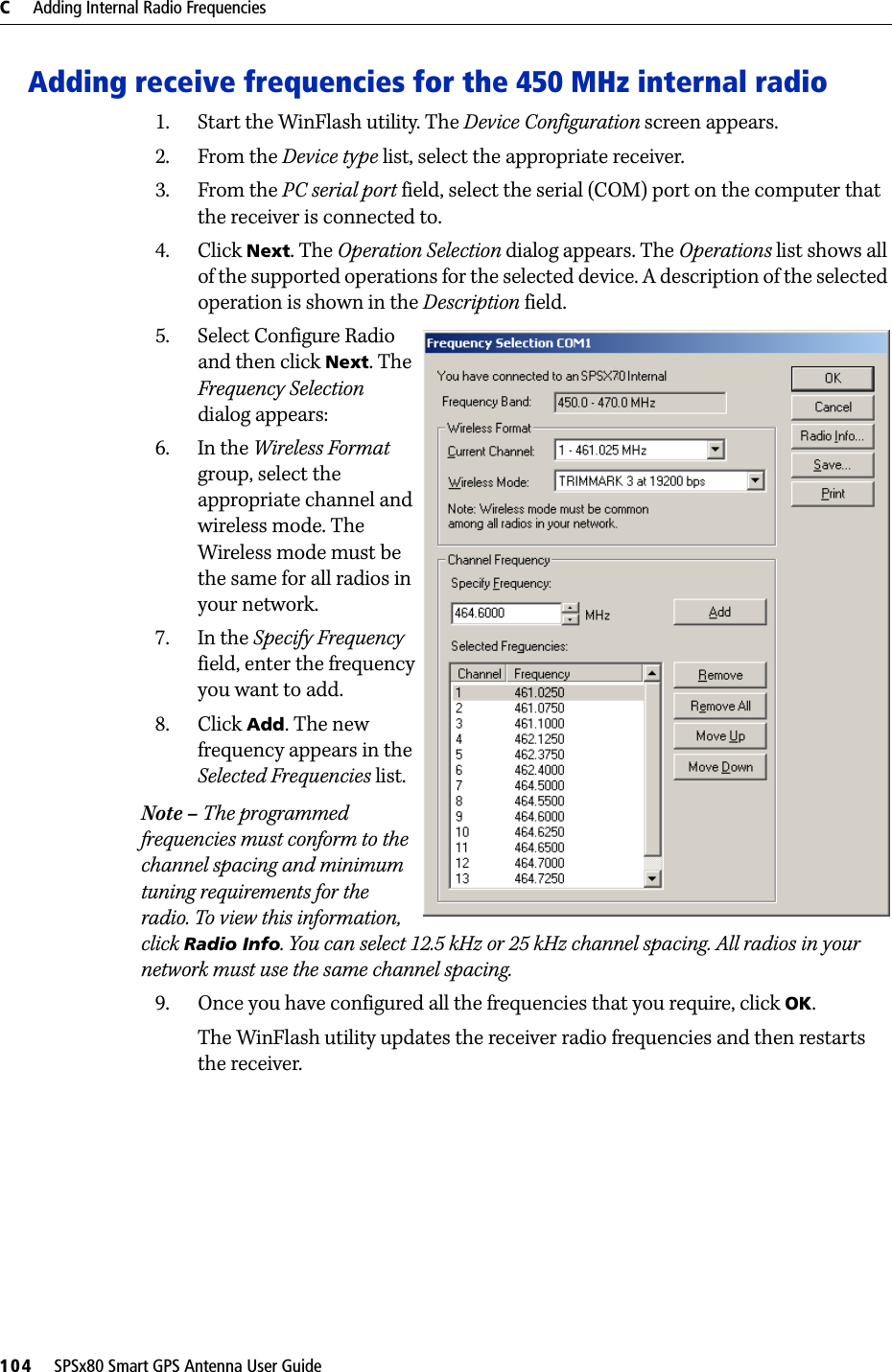

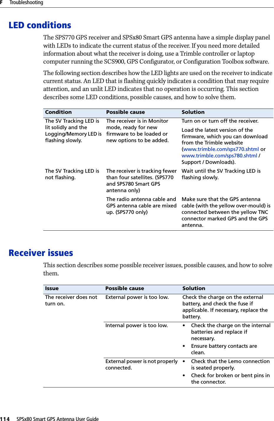
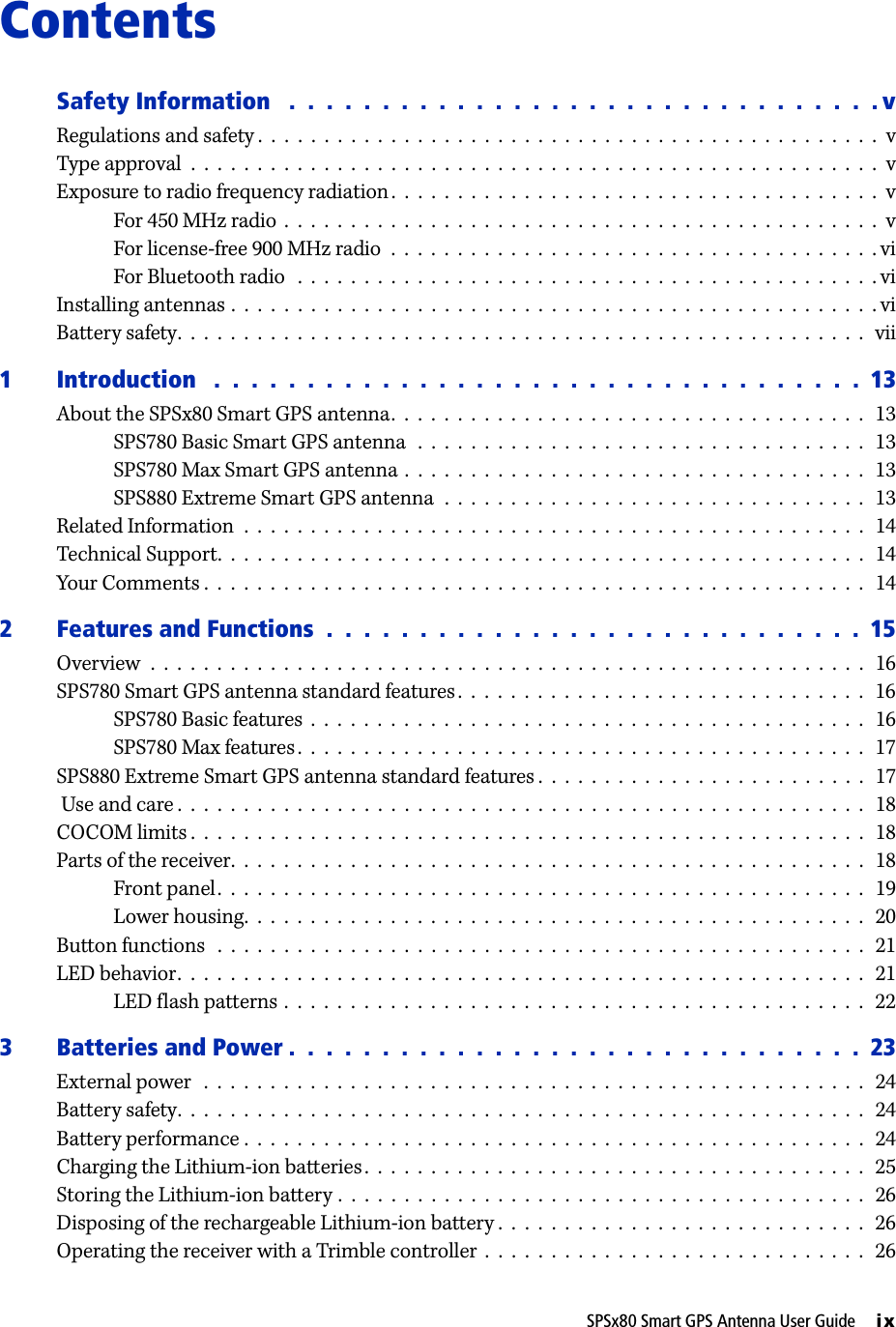
![SPSx80 Smart GPS Antenna User Guide 115Troubleshooting FFaulty external power cable. • Try a different cable.• Check pinouts with multimeter to ensure internal wiring is intact.Receiver does not log data.Insufficient memory on either internal memory or the CompactFlash card.Delete old files using the GPS Configurator software, or press E for 30 seconds.No CompactFlash card is inserted. (SPS770 only)Insert a CompactFlash card in the receiver.The CompactFlash card is not seated properly.Remove the Compact Flash card and reinsert it. Ensure that it slides into the housing easily and seats into the connector.The CompactFlash card is not formatted, or has been corrupted.Format the CompactFlash card using the GPS Configurator software, or press E for 30 seconds. If the problem persists, use the GPS Configurator software to perform a full format.The receiver is tracking fewer than four satellites.• Wait until the SV Tracking LED is flashing slowly.• Use the SCS900 software. Go to the SkyPlot screen and press [Ctrl]+[M] to access the current elevation mask settings. Reduce the mask value to make more satellites available. The default mask setting for receiver is 13° above the horizon. Change the value to a lower setting temporarily while you are waiting for a better constellation availability.The data logging option is not enabled.Check the original purchase order or the receiver configuration using WinFlash. If data logging is not enabled on the receiver, you can order the option from your local Trimble Site Positioning Systems dealer, and upgrade the receiver using the WinFlash utility.Receiver is not tracking any satellitesGPS antenna does not have clear line of sight to the sky.Ensure that the antenna has a clear line of sight.The cable between receiver and the GPS antenna is damaged.Replace the cable.Cable connections at receiver or antenna are not tightly seated, or are connected incorrectly.Check all cable connections.Issue Possible cause Solution](https://usermanual.wiki/Trimble/6248192-B1/User-Guide-882580-Page-115.png)