Trimble 6248192-B1 GPS Rx with BT and 900 MHz FHSS Tx User Manual SPSx80 Smart GPS Antenna User Guide
Trimble Navigation Ltd GPS Rx with BT and 900 MHz FHSS Tx SPSx80 Smart GPS Antenna User Guide
Trimble >
User Manual
Version 2.28 (SPS780 Smart GPS Antennas)
Version 3.20 (SPS880 Smart GPS Antennas)
Revision A
August 2006
USER GUIDE
Trimble® SPSx80 Smart GPS Antenna

Corporate Office
Trimble Navigation Limited
935 Stewart Drive
Sunnyvale, CA 94085
USA
www.trimble.com
Construction Business Area
Trimble Navigation Limited
Construction Business Area
5475 Kellenburger Road
Dayton, Ohio 45424-1099
USA
800-538-7800 (toll free in USA)
+1-937-245-5600 Phone
+1-937-233-9004 Fax
www.trimble.com
E-mail: trimble_support@trimble.com
Legal Notices
Copyright and Trademarks
© 2006, Trimble Navigation Limited. All rights reserved.
Trimble and the Globe & Triangle logo are trademarks of Trimble
Navigation Limited, registered in the United States Patent and
Trademark Office and in other countries. AutoBase, CMR, CMR+,
HydroPro, Maxwell, TRIMMARK, Trimble Geomatics Office,
Trimble Total Control, TSC2, TSCe, VRS, Zephyr, and Zephyr
Geodetic are trademarks of Trimble Navigation Limited.
The Bluetooth word mark and logos are owned by the Bluetooth
SIG, Inc. and any use of such marks by Trimble Navigation Limited
is under license.
Microsoft, Windows, and Windows NT, are either registered
trademarks or trademarks of Microsoft Corporation in the United
States and/or other countries.
All other trademarks are the property of their respective owners.
Release Notice
This is the August 2006 release (Revision A) of the SPSx80 Smart
GPS Antenna User Guide. It applies to version 2.28 and 3.20 of the
SPSx80 Smart GPS antennas.
Product Limited Warranty Information
LIMITED WARRANTY TERMS AND CONDITIONS
Product Limited Warranty
Subject to the following terms and conditions, Trimble Navigation
Limited (“Trimble”) warrants that for a period of one (1) year from
date of purchase this Trimble product (the “Product”) will
substantially conform to Trimble's publicly available specifications
for the Product and that the hardware and any storage media
components of the Product will be substantially free from defects in
materials and workmanship.
Product Software
Product software, whether built into hardware circuitry as
firmware, provided as a standalone computer software product,
embedded in flash memory, or stored on magnetic or other media,
is licensed solely for use with or as an integral part of the Product
and is not sold. If accompanied by a separate end user license
agreement (“EULA”), use of any such software will be subject to the
terms of such end user license agreement (including any differing
limited warranty terms, exclusions, and limitations), which shall
control over the terms and conditions set forth in this limited
warranty.
Software Fixes
During the limited warranty period you will be entitled to receive
such Fixes to the Product software that Trimble releases and makes
commercially available and for which it does not charge separately,
subject to the procedures for delivery to purchasers of Trimble
products generally. If you have purchased the Product from an
authorized Trimble dealer rather than from Trimble directly,
Trimble may, at its option, forward the software Fix to the Trimble
dealer for final distribution to you. Minor Updates, Major Upgrades,
new products, or substantially new software releases, as identified
by Trimble, are expressly excluded from this update process and
limited warranty. Receipt of software Fixes or other enhancements
shall not serve to extend the limited warranty period.
For purposes of this warranty the following definitions shall apply:
(1) “Fix(es)” means an error correction or other update created to fix
a previous software version that does not substantially conform to
its Trimble specifications; (2) “Minor Update” occurs when
enhancements are made to current features in a software program;
and (3) “Major Upgrade” occurs when significant new features are
added to software, or when a new product containing new features
replaces the further development of a current product line. Trimble
reserves the right to determine, in its sole discretion, what
constitutes a Fix, Minor Update, or Major Upgrade.
Warranty Remedies
If the Trimble Product fails during the warranty period for reasons
covered by this limited warranty and you notify Trimble of such
failure during the warranty period, Trimble will repair OR replace
the nonconforming Product with new, equivalent to new, or
reconditioned parts or Product, OR refund the Product purchase
price paid by you, at Trimble’s option, upon your return of the
Product in accordance with Trimble's product return procedures
then in effect.
How to Obtain Warranty Service
To obtain warranty service for the Product, please contact your
local Trimble authorized dealer. Alternatively, you may contact
Trimble to request warranty service at +1-408-481-6940 (24 hours a
day) or e-mail your request to trimble_support@trimble.com.
Please be prepared to provide:
– your name, address, and telephone numbers
– proof of purchase
– a copy of this Trimble warranty
– a description of the nonconforming Product including the model
number
– an explanation of the problem
The customer service representative may need additional
information from you depending on the nature of the problem.
Warranty Exclusions and Disclaimer
This Product limited warranty shall only apply in the event and to
the extent that (a) the Product is properly and correctly installed,
configured, interfaced, maintained, stored, and operated in
accordance with Trimble's applicable operator's manual and
specifications, and; (b) the Product is not modified or misused. This
Product limited warranty shall not apply to, and Trimble shall not
be responsible for, defects or performance problems resulting from
(i) the combination or utilization of the Product with hardware or
software products, information, data, systems, interfaces, or devices
not made, supplied, or specified by Trimble; (ii) the operation of the
Product under any specification other than, or in addition to,
Trimble's standard specifications for its products; (iii) the
unauthorized installation, modification, or use of the Product; (iv)
damage caused by: accident, lightning or other electrical discharge,
fresh or salt water immersion or spray (outside of Product
specifications); or exposure to environmental conditions for which
the Product is not intended; (v) normal wear and tear on
consumable parts (e.g., batteries); or (vi) cosmetic damage. Trimble
does not warrant or guarantee the results obtained through the use
of the Product, or that software components will operate error free.
NOTICE REGARDING PRODUCTS EQUIPPED WITH TECHNOLOGY
CAPABLE OF TRACKING SATELLITE SIGNALS FROM SATELLITE BASED
AUGMENTATION SYSTEMS (SBAS) (WAAS/EGNOS, AND MSAS),
OMNISTAR, GPS, MODERNIZED GPS OR GLONASS SATELLITES, OR
FROM IALA BEACON SOURCES:TRIMBLE IS NOT RESPONSIBLE FOR
THE OPERATION OR FAILURE OF OPERATION OF ANY SATELLITE
BASED POSITIONING SYSTEM OR THE AVAILABILITY OF ANY
SATELLITE BASED POSITIONING SIGNALS.
THE FOREGOING LIMITED WARRANTY TERMS STATE TRIMBLE’S
ENTIRE LIABILITY, AND YOUR EXCLUSIVE REMEDIES, RELATING TO
THE TRIMBLE PRODUCT. EXCEPT AS OTHERWISE EXPRESSLY
PROVIDED HEREIN, THE PRODUCT, AND ACCOMPANYING
DOCUMENTATION AND MATERIALS ARE PROVIDED “AS-IS” AND
WITHOUT EXPRESS OR IMPLIED WARRANTY OF ANY KIND, BY
EITHER TRIMBLE OR ANYONE WHO HAS BEEN INVOLVED IN ITS
CREATION, PRODUCTION, INSTALLATION, OR DISTRIBUTION,
INCLUDING, BUT NOT LIMITED TO, THE IMPLIED WARRANTIES OF
MERCHANTABILITY AND FITNESS FOR A PARTICULAR PURPOSE,
TITLE, AND NONINFRINGEMENT. THE STATED EXPRESS
WARRANTIES ARE IN LIEU OF ALL OBLIGATIONS OR LIABILITIES ON
THE PART OF TRIMBLE ARISING OUT OF, OR IN CONNECTION WITH,
ANY PRODUCT. BECAUSE SOME STATES AND JURISDICTIONS DO NOT
ALLOW LIMITATIONS ON DURATION OR THE EXCLUSION OF AN
IMPLIED WARRANTY, THE ABOVE LIMITATION MAY NOT APPLY OR
FULLY APPLY TO YOU.
Limitation of Liability
TRIMBLE'S ENTIRE LIABILITY UNDER ANY PROVISION HEREIN SHALL
BE LIMITED TO THE AMOUNT PAID BY YOU FOR THE PRODUCT. TO
THE MAXIMUM EXTENT PERMITTED BY APPLICABLE LAW, IN NO
EVENT SHALL TRIMBLE OR ITS SUPPLIERS BE LIABLE FOR ANY
INDIRECT, SPECIAL, INCIDENTAL, OR CONSEQUENTIAL DAMAGE
WHATSOEVER UNDER ANY CIRCUMSTANCE OR LEGAL THEORY
RELATING IN ANYWAY TO THE PRODUCTS, SOFTWARE AND
ACCOMPANYING DOCUMENTATION AND MATERIALS, (INCLUDING,
WITHOUT LIMITATION, DAMAGES FOR LOSS OF BUSINESS PROFITS,

BUSINESS INTERRUPTION, LOSS OF DATA, OR ANY OTHER
PECUNIARY LOSS), REGARDLESS OF WHETHER TRIMBLE HAS BEEN
ADVISED OF THE POSSIBILITY OF ANY SUCH LOSS AND REGARDLESS
OF THE COURSE OF DEALING WHICH DEVELOPS OR HAS
DEVELOPED BETWEEN YOU AND TRIMBLE. BECAUSE SOME STATES
AND JURISDICTIONS DO NOT ALLOW THE EXCLUSION OR
LIMITATION OF LIABILITY FOR CONSEQUENTIAL OR INCIDENTAL
DAMAGES, THE ABOVE LIMITATION MAY NOT APPLY TO YOU.
PLEASE NOTE: THE ABOVE TRIMBLE LIMITED WARRANTY PROVISIONS
WILL NOT APPLY TO PRODUCTS PURCHASED IN THOSE
JURISDICTIONS (E.G., MEMBER STATES OF THE EUROPEAN ECONOMIC
AREA) IN WHICH PRODUCT WARRANTIES ARE THE RESPONSIBILITY
OF THE LOCAL TRIMBLE AUTHORIZED DEALER FROM WHOM THE
PRODUCTS ARE ACQUIRED. IN SUCH A CASE, PLEASE CONTACT YOUR
LOCAL TRIMBLE AUTHORIZED DEALER FOR APPLICABLE WARRANTY
INFORMATION.
Official Language
THE OFFICIAL LANGUAGE OF THESE TERMS AND CONDITIONS IS
ENGLISH. IN THE EVENT OF A CONFLICT BETWEEN ENGLISH AND
OTHER LANGUAGE VERSIONS, THE ENGLISH LANGUAGE SHALL
CONTROL.
Registration
To receive information regarding updates and new products, please
contact your local dealer or visit the Trimble website at
www.trimble.com/register. Upon registration you may select the
newsletter, upgrade, or new product information you desire.
Notices
Class B Statement – Notice to Users. This equipment has been
tested and found to comply with the limits for a Class B digital
device, pursuant to Part 15 of the FCC rules. These limits are
designed to provide reasonable protection against harmful
interference in a residential installation. This equipment generates,
uses, and can radiate radio frequency energy and, if not installed
and used in accordance with the instructions, may cause harmful
interference to radio communication. However, there is no
guarantee that interference will not occur in a particular
installation. If this equipment does cause harmful interference to
radio or television reception, which can be determined by turning
the equipment off and on, the user is encouraged to try to correct
the interference by one or more of the following measures:
– Reorient or relocate the receiving antenna.
– Increase the separation between the equipment and the receiver.
– Connect the equipment into an outlet on a circuit different from
that to which the receiver is connected.
– Consult the dealer or an experienced radio/TV technician for
help.
Changes and modifications not expressly approved by the
manufacturer or registrant of this equipment can void your
authority to operate this equipment under Federal
Communications Commission rules.
Canada
This digital apparatus does not exceed the Class B limits for radio
noise emissions from digital apparatus as set out in the radio
interference regulations of the Canadian Department of
Communications.
Le présent appareil numérique n’émet pas de bruits
radioélectriques dépassant les limites applicables aux appareils
numériques de Classe B prescrites dans le règlement sur le
brouillage radioélectrique édicté par le Ministère des
Communications du Canada.
Europe
This product has been tested and found to comply with the
requirements for a Class B device pursuant to European
Council Directive 89/336/EEC on EMC, thereby satisfying
the requirements for CE Marking and sale within the European
Economic Area (EEA). Contains Infineon radio module ROK 104001.
These requirements are designed to provide reasonable protection
against harmful interference when the equipment is operated in a
residential or commercial environment.
Australia and New Zealand
This product conforms with the regulatory requirements of
the Australian Communications Authority (ACA) EMC
framework, thus satisfying the requirements for C-Tick
Marking and sale within Australia and New Zealand.
Taiwan – Battery Recycling Requirements
The product contains a removable Lithium-ion battery.
Taiwanese regulations require that waste batteries are
recycled.
廢電池請回收
Notice to Our European Union Customers
For product recycling instructions and more information, please go
to www.trimble.com/ev.shtml.
Recycling in Europe: To recycle Trimble WEEE (Waste
Electrical and Electronic Equipment, products that run on
electrical power.), Call +31 497 53 24 30, and ask for the
"WEEE Associate". Or, mail a request for recycling
instructions to:
Trimble Europe BV
c/o Menlo Worldwide Logistics
Meerheide 45
5521 DZ Eersel, NL
iv SPSx80 Smart GPS Antenna User Guide
SPSx80 Smart GPS Antenna User Guide v
Safety Information
Before you use your Trimble® SPS GPS receiver, make sure that you have read and
understood all safety requirements.
Regulations and safety
The receivers contain an internal radio-modem and can send signals through
Bluetooth® wireless technology (SPSx50 Modular GPS receiver and the SPSx80 Smart
GPS antenna only) or through an external data communications radio. Regulations
regarding the use of the radio-modems vary greatly from country to country. In some
countries, the unit can be used without obtaining an end-user license. Other countries
require end-user licensing. For licensing information, consult your local Trimble dealer.
Before operating an SPSx50 Modular GPS receiver or SPSx80 Smart GPS antenna,
determine if authorization or a license to operate the unit is required in your country. It
is the responsibility of the end user to obtain an operator’s permit or license for the
receiver for the location or country of use.
For FCC regulations, see Notices, page iii.
Type approval
Type approval, or acceptance, covers technical parameters of the equipment related to
emissions that can cause interference. Type approval is granted to the manufacturer of
the transmission equipment, independent from the operation or licensing of the units.
Some countries have unique technical requirements for operation in particular
radio-modem frequency bands. To comply with those requirements, Trimble may have
modified your equipment to be granted Type approval. Unauthorized modification of
the units voids the Type approval, the warranty, and the operational license of the
equipment.
Exposure to radio frequency radiation
For 450 MHz radio
Safety. Exposure to RF energy is an important safety consideration. The FCC has
adopted a safety standard for human exposure to radio frequency electromagnetic
energy emitted by FCC regulated equipment as a result of its actions in General Docket
79-144 on March 13, 1986.
Proper use of this radio modem results in exposure below government limits. The
following precautions are recommended:
•DO NOT operate the transmitter when someone is 20 cm (7.8 inches) of the
antenna.
•DO NOT operate the transmitter unless all RF connectors are secure and any
open connectors are properly terminated.

Safety Information
vi SPSx80 Smart GPS Antenna User Guide
•DO NOT operate the equipment near electrical blasting caps or in an explosive
atmosphere.
•All equipment must be properly grounded according to Trimble installation
instructions for safe operation.
•All equipment should be serviced only by a qualified technician.
For license-free 900 MHz radio1
CCAUTION – For your own safety, and in terms of the RF Exposure requirements of the
FCC, always observe the precautions listed here.
•Always maintain a minimum separation distance of 20 cm (7.8 inches) between
yourself and the radiating antenna on the SPSx50 radio-modem.
•Do not co-locate the antenna with any other transmitting device.
For Bluetooth radio
The radiated output power of the internal Bluetooth wireless radio is far below the
FCC radio frequency exposure limits. Nevertheless, the wireless radio shall be used in
such a manner that the Trimble receiver is 20 cm or further from the human body. The
internal wireless radio operates within guidelines found in radio frequency safety
standards and recommendations, which reflect the consensus of the scientific
community. Trimble therefore believes the internal wireless radio is safe for use by
consumers. The level of energy emitted is far less than the electromagnetic energy
emitted by wireless devices such as mobile phones. However, the use of wireless radios
may be restricted in some situations or environments, such as on aircraft. If you are
unsure of restrictions, you are encouraged to ask for authorization before turning on
the wireless radio.
Installing antennas
CCAUTION – For your own safety, and in terms of the RF Exposure requirements of the
FCC, always observe these precautions:
– Always maintain a minimum separation distance of 20 cm (7.8 inches) between yourself
and the radiating antenna.
– Do not co-locate the antenna with any other transmitting device.
This device has been designed to operate with the antennas listed below, and having a
maximum gain of 5 dBi. Antennas not included in this list, or having a gain greater
than 5 dBi, are strictly prohibited for use with this device. The required antenna
impedance is 50 ohms.
The antennas to be used with the 450 MHz radio are 0 dBi and 5 dBi whip antennas.
The antennas to be used with the 900MHz radio are 0dBi, 3dBi, and 5dBi whip
antennas.
1. 900 Mhz radios are not used in Europe.

SPSx80 Smart GPS Antenna User Guide vii
Safety Information
To reduce potential radio interference to other users, the antenna type and its gain
should be so chosen that the equivalent isotropically radiated power (e.i.r.p.) is not
more than that permitted for successful communication.
Battery safety
CWARNING – Do not damage the rechargeable Lithium-ion battery. A damaged battery
can cause an explosion or fire, and can result in personal injury and/or property damage.
To prevent injury or damage:
– Do not use or charge the battery if it appears to be damaged. Signs of damage include,
but are not limited to, discoloration, warping, and leaking battery fluid.
– Do not expose the battery to fire, high temperature, or direct sunlight.
– Do not immerse the battery in water.
– Do not use or store the battery inside a vehicle during hot weather.
– Do not drop or puncture the battery.
– Do not open the battery or short-circuit its contacts.
CWARNING – Avoid contact with the rechargeable Lithium-ion battery if it appears to be
leaking. Battery fluid is corrosive, and contact with it can result in personal injury and/or
property damage.
To prevent injury or damage:
– If the battery leaks, avoid contact with the battery fluid.
– If battery fluid gets into your eyes, immediately rinse your eyes with clean water and
seek medical attention. Do not rub your eyes!
– If battery fluid gets onto your skin or clothing, immediately use clean water to wash off
the battery fluid.
CWARNING – Charge and use the rechargeable Lithium-ion battery only in strict
accordance with the instructions. Charging or using the battery in unauthorized
equipment can cause an explosion or fire, and can result in personal injury and/or
equipment damage.
To prevent injury or damage:
– Do not charge or use the battery if it appears to be damaged or leaking.
– Charge the Lithium-ion battery only in a Trimble product that is specified to charge it.
Be sure to follow all instructions that are provided with the battery charger.
– Discontinue charging a battery that gives off extreme heat or a burning odor.
– Use the battery only in Trimble equipment that is specified to use it.
– Use the battery only for its intended use and according to the instructions in the product
documentation.

Safety Information
viii SPSx80 Smart GPS Antenna User Guide
SPSx80 Smart GPS Antenna User Guide ix
Contents
Safety Information . . . . . . . . . . . . . . . . . . . . . . . . . . . . . . . . v
Regulations and safety . . . . . . . . . . . . . . . . . . . . . . . . . . . . . . . . . . . . . . . . . . . . . . . v
Type approval . . . . . . . . . . . . . . . . . . . . . . . . . . . . . . . . . . . . . . . . . . . . . . . . . . . . v
Exposure to radio frequency radiation . . . . . . . . . . . . . . . . . . . . . . . . . . . . . . . . . . . . . v
For 450 MHz radio . . . . . . . . . . . . . . . . . . . . . . . . . . . . . . . . . . . . . . . . . . . . . v
For license-free 900 MHz radio . . . . . . . . . . . . . . . . . . . . . . . . . . . . . . . . . . . . . vi
For Bluetooth radio . . . . . . . . . . . . . . . . . . . . . . . . . . . . . . . . . . . . . . . . . . . . vi
Installing antennas . . . . . . . . . . . . . . . . . . . . . . . . . . . . . . . . . . . . . . . . . . . . . . . . . vi
Battery safety. . . . . . . . . . . . . . . . . . . . . . . . . . . . . . . . . . . . . . . . . . . . . . . . . . . . vii
1 Introduction . . . . . . . . . . . . . . . . . . . . . . . . . . . . . . . . . . . 13
About the SPSx80 Smart GPS antenna. . . . . . . . . . . . . . . . . . . . . . . . . . . . . . . . . . . . 13
SPS780 Basic Smart GPS antenna . . . . . . . . . . . . . . . . . . . . . . . . . . . . . . . . . . 13
SPS780 Max Smart GPS antenna . . . . . . . . . . . . . . . . . . . . . . . . . . . . . . . . . . . 13
SPS880 Extreme Smart GPS antenna . . . . . . . . . . . . . . . . . . . . . . . . . . . . . . . . 13
Related Information . . . . . . . . . . . . . . . . . . . . . . . . . . . . . . . . . . . . . . . . . . . . . . . 14
Technical Support. . . . . . . . . . . . . . . . . . . . . . . . . . . . . . . . . . . . . . . . . . . . . . . . . 14
Your Comments . . . . . . . . . . . . . . . . . . . . . . . . . . . . . . . . . . . . . . . . . . . . . . . . . . 14
2 Features and Functions . . . . . . . . . . . . . . . . . . . . . . . . . . . . . 15
Overview . . . . . . . . . . . . . . . . . . . . . . . . . . . . . . . . . . . . . . . . . . . . . . . . . . . . . . 16
SPS780 Smart GPS antenna standard features . . . . . . . . . . . . . . . . . . . . . . . . . . . . . . . 16
SPS780 Basic features . . . . . . . . . . . . . . . . . . . . . . . . . . . . . . . . . . . . . . . . . . 16
SPS780 Max features. . . . . . . . . . . . . . . . . . . . . . . . . . . . . . . . . . . . . . . . . . . 17
SPS880 Extreme Smart GPS antenna standard features . . . . . . . . . . . . . . . . . . . . . . . . . 17
Use and care . . . . . . . . . . . . . . . . . . . . . . . . . . . . . . . . . . . . . . . . . . . . . . . . . . . . 18
COCOM limits . . . . . . . . . . . . . . . . . . . . . . . . . . . . . . . . . . . . . . . . . . . . . . . . . . . 18
Parts of the receiver. . . . . . . . . . . . . . . . . . . . . . . . . . . . . . . . . . . . . . . . . . . . . . . . 18
Front panel. . . . . . . . . . . . . . . . . . . . . . . . . . . . . . . . . . . . . . . . . . . . . . . . . 19
Lower housing. . . . . . . . . . . . . . . . . . . . . . . . . . . . . . . . . . . . . . . . . . . . . . . 20
Button functions . . . . . . . . . . . . . . . . . . . . . . . . . . . . . . . . . . . . . . . . . . . . . . . . . 21
LED behavior. . . . . . . . . . . . . . . . . . . . . . . . . . . . . . . . . . . . . . . . . . . . . . . . . . . . 21
LED flash patterns . . . . . . . . . . . . . . . . . . . . . . . . . . . . . . . . . . . . . . . . . . . . 22
3 Batteries and Power . . . . . . . . . . . . . . . . . . . . . . . . . . . . . . . 23
External power . . . . . . . . . . . . . . . . . . . . . . . . . . . . . . . . . . . . . . . . . . . . . . . . . . 24
Battery safety. . . . . . . . . . . . . . . . . . . . . . . . . . . . . . . . . . . . . . . . . . . . . . . . . . . . 24
Battery performance . . . . . . . . . . . . . . . . . . . . . . . . . . . . . . . . . . . . . . . . . . . . . . . 24
Charging the Lithium-ion batteries. . . . . . . . . . . . . . . . . . . . . . . . . . . . . . . . . . . . . . 25
Storing the Lithium-ion battery . . . . . . . . . . . . . . . . . . . . . . . . . . . . . . . . . . . . . . . . 26
Disposing of the rechargeable Lithium-ion battery . . . . . . . . . . . . . . . . . . . . . . . . . . . . 26
Operating the receiver with a Trimble controller . . . . . . . . . . . . . . . . . . . . . . . . . . . . . 26

Contents
x SPSx80 Smart GPS Antenna User Guide
4 Setup Guidelines . . . . . . . . . . . . . . . . . . . . . . . . . . . . . . . . . 27
Base station operation guidelines . . . . . . . . . . . . . . . . . . . . . . . . . . . . . . . . . . . . . . . 28
Base station components. . . . . . . . . . . . . . . . . . . . . . . . . . . . . . . . . . . . . . . . 28
Base station setup guidelines . . . . . . . . . . . . . . . . . . . . . . . . . . . . . . . . . . . . . 29
Permanent installation antenna cabling for the SPSx50 Modular GPS receiver and
SPS770 GPS receiver . . . . . . . . . . . . . . . . . . . . . . . . . . . . . . . . . . . . . . . . . 31
Rover operation guidelines . . . . . . . . . . . . . . . . . . . . . . . . . . . . . . . . . . . . . . . . . . . 31
Rover receiver components . . . . . . . . . . . . . . . . . . . . . . . . . . . . . . . . . . . . . . 32
Rover receiver setup guidelines . . . . . . . . . . . . . . . . . . . . . . . . . . . . . . . . . . . . 33
Cellular modem and external radio . . . . . . . . . . . . . . . . . . . . . . . . . . . . . . . . . 36
5 Setting up the Receiver . . . . . . . . . . . . . . . . . . . . . . . . . . . . . 37
Connecting the receiver to external devices . . . . . . . . . . . . . . . . . . . . . . . . . . . . . . . . 38
Trimble controller with SCS900 Site Controller software . . . . . . . . . . . . . . . . . . . . 38
External radio-modems. . . . . . . . . . . . . . . . . . . . . . . . . . . . . . . . . . . . . . . . . 39
Common ways to set up a base station . . . . . . . . . . . . . . . . . . . . . . . . . . . . . . . . . . . 40
Setting up a base station for permanent or semi-permanent installation. . . . . . . . . . 40
Setting up a base station for daily site use: T-Bar . . . . . . . . . . . . . . . . . . . . . . . . . 41
Setting up a mobile base station: Tripod and fixed height tripod . . . . . . . . . . . . . . . 42
Common ways to set up a rover receiver . . . . . . . . . . . . . . . . . . . . . . . . . . . . . . . . . . 45
Setting up the rover receiver on a jobsite vehicle . . . . . . . . . . . . . . . . . . . . . . . . . 45
Setting up the rover receiver on a rod . . . . . . . . . . . . . . . . . . . . . . . . . . . . . . . . 47
Setting up a rover receiver on a belt or in a backpack . . . . . . . . . . . . . . . . . . . . . . 48
6 Configuring the Receiver Settings . . . . . . . . . . . . . . . . . . . . . . . 51
Using the SCS900 Site Controller software to configure the base station, the rover, and
the radios . . . . . . . . . . . . . . . . . . . . . . . . . . . . . . . . . . . . . . . . . . . . . . . . . . . . 52
Configuring the receiver to log data for postprocessing . . . . . . . . . . . . . . . . . . . . . . . . . 53
Configuring the receiver in real time . . . . . . . . . . . . . . . . . . . . . . . . . . . . . . . . . . . . . 53
Configuring the receiver using application files . . . . . . . . . . . . . . . . . . . . . . . . . . . . . . 53
Overview . . . . . . . . . . . . . . . . . . . . . . . . . . . . . . . . . . . . . . . . . . . . . . . . . . 53
Special application files . . . . . . . . . . . . . . . . . . . . . . . . . . . . . . . . . . . . . . . . . 54
Applying application files. . . . . . . . . . . . . . . . . . . . . . . . . . . . . . . . . . . . . . . . 55
Storing application files . . . . . . . . . . . . . . . . . . . . . . . . . . . . . . . . . . . . . . . . . 55
Naming application files . . . . . . . . . . . . . . . . . . . . . . . . . . . . . . . . . . . . . . . . 56
Creating and editing the configuration files that control the receiver . . . . . . . . . . . . . . . . 56
Installing the Configuration Toolbox software. . . . . . . . . . . . . . . . . . . . . . . . . . . 56
Configuring the receiver using the Configuration Toolbox software . . . . . . . . . . . . . 57
Transmitting the application file to the receiver . . . . . . . . . . . . . . . . . . . . . . . . . 58
7 AutoBase Feature . . . . . . . . . . . . . . . . . . . . . . . . . . . . . . . . 59
Setting Up a Base Station . . . . . . . . . . . . . . . . . . . . . . . . . . . . . . . . . . . . . . . . . . . . 60
Best practice . . . . . . . . . . . . . . . . . . . . . . . . . . . . . . . . . . . . . . . . . . . . . . . . 60
Antenna type . . . . . . . . . . . . . . . . . . . . . . . . . . . . . . . . . . . . . . . . . . . . . . . 60

SPSx80 Smart GPS Antenna User Guide xi
Contents
Scenarios . . . . . . . . . . . . . . . . . . . . . . . . . . . . . . . . . . . . . . . . . . . . . . . . . . . . . . 61
Scenario One: Base station setup on first visit to a site . . . . . . . . . . . . . . . . . . . . . 61
Scenario Two: Base station setup on a repeat visit to that site . . . . . . . . . . . . . . . . 61
Scenario Three: The stored base station position seems to be missing . . . . . . . . . . . 62
Flowchart showing the AutoBase process . . . . . . . . . . . . . . . . . . . . . . . . . . . . . . . . . 63
8 Default Settings . . . . . . . . . . . . . . . . . . . . . . . . . . . . . . . . . 65
Default receiver settings. . . . . . . . . . . . . . . . . . . . . . . . . . . . . . . . . . . . . . . . . . . . . 66
Resetting the receiver to factory defaults . . . . . . . . . . . . . . . . . . . . . . . . . . . . . . . . . . 66
Default behavior. . . . . . . . . . . . . . . . . . . . . . . . . . . . . . . . . . . . . . . . . . . . . . . . . . 67
Power up settings . . . . . . . . . . . . . . . . . . . . . . . . . . . . . . . . . . . . . . . . . . . . . . . . . 67
Logging data . . . . . . . . . . . . . . . . . . . . . . . . . . . . . . . . . . . . . . . . . . . . . . . . . . . . 67
Logging data after a power loss . . . . . . . . . . . . . . . . . . . . . . . . . . . . . . . . . . . . 67
9 Specifications. . . . . . . . . . . . . . . . . . . . . . . . . . . . . . . . . . . 69
General specifications . . . . . . . . . . . . . . . . . . . . . . . . . . . . . . . . . . . . . . . . . . . . . . 70
Physical specifications . . . . . . . . . . . . . . . . . . . . . . . . . . . . . . . . . . . . . . . . . . . . . . 70
Electrical specifications . . . . . . . . . . . . . . . . . . . . . . . . . . . . . . . . . . . . . . . . . . . . . 71
Communication specifications . . . . . . . . . . . . . . . . . . . . . . . . . . . . . . . . . . . . . . . . 72
A NMEA-0183 Output . . . . . . . . . . . . . . . . . . . . . . . . . . . . . . . . 73
NMEA-0183 message overview . . . . . . . . . . . . . . . . . . . . . . . . . . . . . . . . . . . . . . . . 74
Common message elements . . . . . . . . . . . . . . . . . . . . . . . . . . . . . . . . . . . . . . . . . . 75
Message values . . . . . . . . . . . . . . . . . . . . . . . . . . . . . . . . . . . . . . . . . . . . . . 75
NMEA messages . . . . . . . . . . . . . . . . . . . . . . . . . . . . . . . . . . . . . . . . . . . . . . . . . 75
B GSOF Messages. . . . . . . . . . . . . . . . . . . . . . . . . . . . . . . . . . 91
Supported message types . . . . . . . . . . . . . . . . . . . . . . . . . . . . . . . . . . . . . . . . . . . . 92
GSOF message definitions . . . . . . . . . . . . . . . . . . . . . . . . . . . . . . . . . . . . . . . . . . . 92
TIME . . . . . . . . . . . . . . . . . . . . . . . . . . . . . . . . . . . . . . . . . . . . . . . . . . . . 92
LLH . . . . . . . . . . . . . . . . . . . . . . . . . . . . . . . . . . . . . . . . . . . . . . . . . . . . . 93
ECEF. . . . . . . . . . . . . . . . . . . . . . . . . . . . . . . . . . . . . . . . . . . . . . . . . . . . . 93
ECEF DELTA. . . . . . . . . . . . . . . . . . . . . . . . . . . . . . . . . . . . . . . . . . . . . . . . 94
NEU DELTA . . . . . . . . . . . . . . . . . . . . . . . . . . . . . . . . . . . . . . . . . . . . . . . . 94
Velocity . . . . . . . . . . . . . . . . . . . . . . . . . . . . . . . . . . . . . . . . . . . . . . . . . . . 95
PDOP . . . . . . . . . . . . . . . . . . . . . . . . . . . . . . . . . . . . . . . . . . . . . . . . . . . . 95
SIGMA . . . . . . . . . . . . . . . . . . . . . . . . . . . . . . . . . . . . . . . . . . . . . . . . . . . 95
SV Brief . . . . . . . . . . . . . . . . . . . . . . . . . . . . . . . . . . . . . . . . . . . . . . . . . . . 96
SV Detail . . . . . . . . . . . . . . . . . . . . . . . . . . . . . . . . . . . . . . . . . . . . . . . . . . 97
UTC . . . . . . . . . . . . . . . . . . . . . . . . . . . . . . . . . . . . . . . . . . . . . . . . . . . . . 98
Batt/Mem . . . . . . . . . . . . . . . . . . . . . . . . . . . . . . . . . . . . . . . . . . . . . . . . . 98
Attitude . . . . . . . . . . . . . . . . . . . . . . . . . . . . . . . . . . . . . . . . . . . . . . . . . . . 99
Flags . . . . . . . . . . . . . . . . . . . . . . . . . . . . . . . . . . . . . . . . . . . . . . . . . . . . .100
Data collector report structure . . . . . . . . . . . . . . . . . . . . . . . . . . . . . . . . . .102

Contents
xii SPSx80 Smart GPS Antenna User Guide
C Adding Internal Radio Frequencies . . . . . . . . . . . . . . . . . . . . . 103
Adding receive frequencies for the 450 MHz internal radio. . . . . . . . . . . . . . . . . . . . . . .104
D Upgrading the Receiver Firmware . . . . . . . . . . . . . . . . . . . . . . 105
The WinFlash utility . . . . . . . . . . . . . . . . . . . . . . . . . . . . . . . . . . . . . . . . . . . . . . .106
Installing the WinFlash utility . . . . . . . . . . . . . . . . . . . . . . . . . . . . . . . . . . . . .106
Upgrading the receiver firmware . . . . . . . . . . . . . . . . . . . . . . . . . . . . . . . . . . . . . . .106
E Data Logging and Postprocessed Measurement Operations . . . . . . . 109
Connecting to the office computer . . . . . . . . . . . . . . . . . . . . . . . . . . . . . . . . . . . . . .110
Transferring files directly from a CompactFlash card . . . . . . . . . . . . . . . . . . . . . . . . . .110
Deleting files in the receiver . . . . . . . . . . . . . . . . . . . . . . . . . . . . . . . . . . . . . . . . . .111
Supported file types . . . . . . . . . . . . . . . . . . . . . . . . . . . . . . . . . . . . . . . . . . . . . . .111
F Troubleshooting . . . . . . . . . . . . . . . . . . . . . . . . . . . . . . . . 113
LED conditions . . . . . . . . . . . . . . . . . . . . . . . . . . . . . . . . . . . . . . . . . . . . . . . . . .114
Receiver issues. . . . . . . . . . . . . . . . . . . . . . . . . . . . . . . . . . . . . . . . . . . . . . . . . . .114
Base station setup and static measurement problems . . . . . . . . . . . . . . . . . . . . . . . . . .116
Glossary . . . . . . . . . . . . . . . . . . . . . . . . . . . . . . . . . . . . . 119

CHAPTER
1
SPSx80 Smart GPS Antenna User Guide 13
Introduction 1
Welcome to the SPSx80 Smart GPS Antenna User
Guide. This manual describes how to set up and
use the Trimble® SPSx80 Smart GPS antennas.
The SPS GPS receivers is a family of receivers that
comprise the SPSx50 Modular GPS receivers,
SPS770 GPS receivers, and the SPSx80 Smart GPS
antennas. Where necessary, this manual contains
references to specific receivers in the product
family. When information is specific to a
particular model, then the specific model name
is used.
Even if you have used other Global Positioning
System (GPS) products before, Trimble
recommends that you spend some time reading
this manual to learn about the special features of
this product. If you are not familiar with GPS,
visit the Trimble website (www.trimble.com) for
an interactive look at Trimble and GPS.
About the SPSx80 Smart GPS
antenna
The SPSx80 Smart GPS antenna family comprises
the following Smart GPS antennas:
•SPS780 Basic
•SPS780 Max
•SPS880 Extreme
The Smart GPS antennas are designed for all
on-the-rod rover operation and rapid daily base
station setup operation.
SPS780 Basic Smart GPS antenna
The SPS780 Basic Smart GPS antenna is the entry
level receiver in the SPSx80 Smart GPS antenna
family. The SPS780 Basic is available as a base
station only or rover only configuration. The
receiver is optimized for use on small-to-midsize
construction projects.
SPS780 Max Smart GPS antenna
The SPS780 Max Smart GPS antenna is available
from new or as an upgrade to the SPS780 Basic
Smart GPS antenna. The SPS780 Max
configuration provides you with base and rover
operation capability plus the ability to work at
longer ranges from the base station, and to
operate as a rover in a Trimble Virtual Reference
Station (VRS™) network.
SPS880 Extreme Smart GPS antenna
The SPS880 Extreme Smart GPS antenna can
track the existing GPS L1 and L2 satellite signals
plus the future L2C and L5 signals as they
become available. The new signals provide the
ability to initialize faster, work in harsher GPS
environments, and work at longer ranges from
the base station. The SPS880 Extreme can also
utilize signals from the Russian GLONASS
satellites, providing increased satellite availability
and fewer/shorter GPS outages.

1 Introduction
14 SPSx80 Smart GPS Antenna User Guide
Related Information
Sources of related information include the
following:
•Help – The SCS900 Site Controller software
has built-in, context-sensitive help that lets
you quickly find the information you need.
Access it from the Help menu. Alternatively,
click the ? button in a dialog, or press [F1]. On
a Microsoft® Windows® CE device, select
Start / Help.
•Release notes – The release notes describe
new features of the product, information not
included in the manuals, and any changes to
the manuals. They are provided as a .pdf file
on the Trimble SPS GPS Receiver CD.
•Trimble training courses – Consider a
training course to help you use your GPS
system to its fullest potential. For more
information, go to the Trimble website at
www.trimble.com/training.html.
Technical Support
If you have a problem and cannot find the
information you need in the product
documentation, contact your local dealer.
Alternatively, go to the Support area of the
Trimble website
(www.trimble.com/support.shtml). Select the
product you need information on. Product
updates, documentation, and any support issues
are available for download.
If you need to contact Trimble technical support,
complete the online inquiry form at
www.trimble.com/support_form.asp.
Your Comments
Your feedback about the supporting
documentation helps us to improve it with each
revision. E-mail your comments to
ReaderFeedback@trimble.com.

CHAPTER
2
SPSx80 Smart GPS Antenna User Guide 15
Features and Functions 2
In this chapter:
QSPS780 Smart GPS antenna
standard features
QSPS880 Extreme Smart GPS
antenna standard features
QUse and care
QCOCOM limits
QParts of the receiver
QButton functions
QLED behavior
The SPSx80 Smart GPS antennas are designed to
be used for the following infrastructure and site
development applications:
•Layout of structure foundations, caissons
and piles
•Earthworks, fine grading and finishing
stakeout operations
•Initial site measurements to verify design
levels and regular subsequent
measurements to determine progress
volumes
•Measurements and grade/thickness checks
on laid materials
The SPSx80 incorporates a GPS antenna,
receiver, internal radio, and battery in a rugged
light-weight unit that is ideally suited as an all-
on-the-pole RTK rover or quick setup/rapid
mobilization base station. LEDs enable you to
monitor satellite tracking, radio reception, data
logging status, and power. Bluetooth® wireless
technology provides cable-free communications
between the receiver and controller.
You can use the SPSx80 as part of an RTK GPS
system with the Trimble SCS900 Site Controller
software.
All the receivers can optionally record GPS data
to the receiver’s optional internal memory and
download to a computer using the serial
connection.
2 Features and Functions
16 SPSx80 Smart GPS Antenna User Guide
Overview
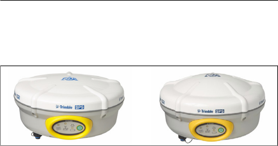
The SPS780 and SPS880 Extreme Smart GPS antennas (see Figure 2.1) are very similar
in setup, operational use, and controls. The SPS880 has a taller antenna dome to
accommodate the larger GPS antenna and the circuitry required to track additional
GPS signals and GLONASS satellites.
Figure 2.1 SPS780 Smart GPS antenna (left), and the SPS880 Extreme Smart GPS antenna (right)
SPS780 Smart GPS antenna standard features
The SPS780 Smart GPS antenna provides the following features:
•Small, lightweight design - 1.31 kg (2.89 lb) (integrated radio, GPS receiver, GPS
antenna and battery) 3.7 kg (8.16 lb) complete system weight (rover including
TSC2 controller and rod)
•The quick setup, high mobility base and rover receiver system is ideal for small
to mid-size jobsites and for working on multiple jobsites on a daily or weekly
basis
•24-channel L1/L2 GPS receiver (SPS780 Basic and SPS780 Max)
•Internal, removable, smart Lithium-ion battery provides up to 6.6 hrs GPS rover
operation per battery
•Bluetooth® wireless technology for cable free, no hassle base or rover operation
•Simple keypad with on/off key and LED indicators for power, radio, and satellite
tracking
•Allows measurement from a moving platform, for example, mounted on a
vehicle or marine vessel for increased efficiency on large jobsites
SPS780 Basic features
•Rover or base configurations, not interchangeable
•2 Hz measurement rover receiver update rate
•Rover operational range limited to 1.5 mile (2.4 km) from base station

SPSx80 Smart GPS Antenna User Guide 17
Features and Functions 2
•Base station operational range limited only by normal restrictions common to
UHF radio transmissions
•Integrated transmit radio (450 MHz Base configuration only)
•Entry level price point for lower cost of base station or rover
•Can be upgraded to the SPS780 Max
SPS780 Max features
•Base/Rover receiver interchangeability for ultimate GPS fleet flexibility
•Rover option offers 10 Hz measurement update rate
•Range limited only by normal restrictions common to UHF radio transmissions
•Operates as a rover within a Virtual Reference Station (VRS) network for
operation without a conventional base station
•Integrated transmit/receive radio provides base station and rover operation
capability (900 MHz variant contains receive only radio and utilizes the SNB900
radio at the base station for transmit capability)
SPS880 Extreme Smart GPS antenna standard features
•Small, lightweight design – 1.35 kg (2.97 lb) (integrated radio, GPS receiver, GPS
antenna and battery) 3.71 kg (8.18 lb) complete system weight (rover including
TSC2 controller and rod)
•The quick setup, high mobility base or rover receiver, is ideal for any size jobsite
as a rover and for working on multiple jobsites on a daily or weekly basis
•72-channel L1/L2/L2C/L5 GPS and L1/L2 GLONASS receiver
•Performs all site measurement and stakeout operations within the operating
range of the radio
•Internal, removable, smart Lithium-ion battery provides up to 5.5 hrs GPS rover
operation per battery
•Bluetooth wireless technology for cable free, no hassle base or rover operation
•Simple keypad with on/off key and LED indicators for power, radio and satellite
tracking
•20 Hz update rate
•Full base/rover interchangeability
•Operates within a VRS network for conventional base station-free rover
capability
•Integrated transmit radio (450MHz version only)
•Receives L2C code and L5 carrier signal for future GPS modernization capability
•Tracks GLONASS L1/L2 signals for increased satellite availability and operation
in harsh GPS environments

2 Features and Functions
18 SPSx80 Smart GPS Antenna User Guide
Use and care
This product is designed to withstand the rough treatment and tough environment
that typically occurs in construction applications. However, the receiver is a
high-precision electronic instrument and should be treated with reasonable care.
CCAUTION – Operating or storing the receiver outside the specified temperature range can
damage it. For more information, see Chapter 10, Specifications.
COCOM limits
The U.S. Department of Commerce requires that all exportable GPS products contain
performance limitations so that they cannot be used in a manner that could threaten
the security of the United States. The following limitations are implemented on this
product:
•Immediate access to satellite measurements and navigation results is disabled
when the receiver velocity is computed to be greater than 1000 knots, or its
altitude is computed to be above 18 000 meters. The receiver GPS subsystem
resets until the COCOM situation clears. As a result, all logging and stream
configurations stop until the GPS subsystem is cleared.
Parts of the receiver
All operating controls on the SPSx80 Smart GPS antenna are located on the front
panel. Serial ports and connectors are located on the bottom of the unit.
SPSx80 Smart GPS Antenna User Guide 19
Features and Functions 2
Front panel
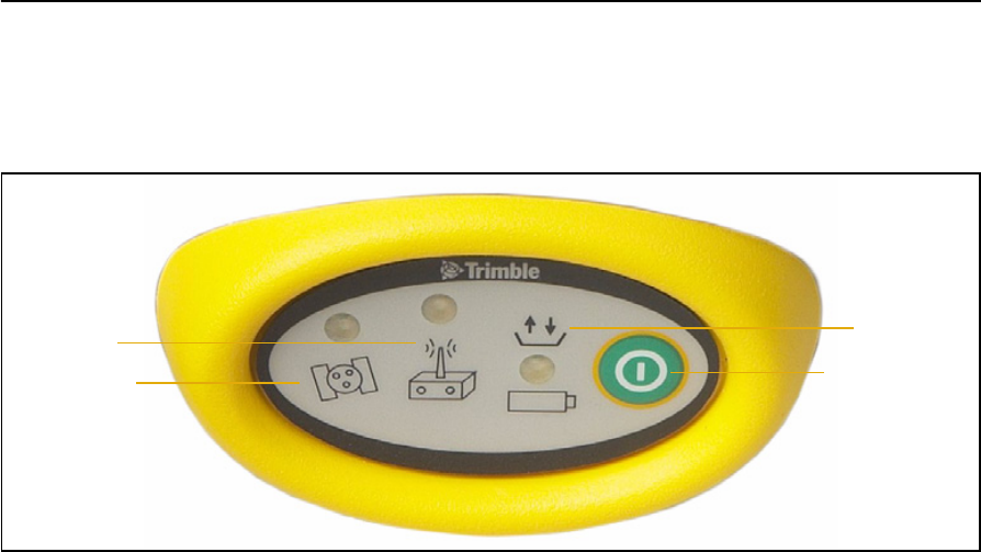
Figure 2.2 shows a front view of the SPSx80 Smart GPS antenna. The front panel
contains the three indicator LEDs, and the power button.
Figure 2.2 Front panel of the SPSx80 Smart GPS antenna
The power button controls the receiver’s power on or off functions.
The indicator LEDs show the status of power, satellite tracking, and radio reception.
For more information, see LED behavior, page 21.
Satellite LED
Radio LED Power LED
Power button
2 Features and Functions
20 SPSx80 Smart GPS Antenna User Guide
Lower housing
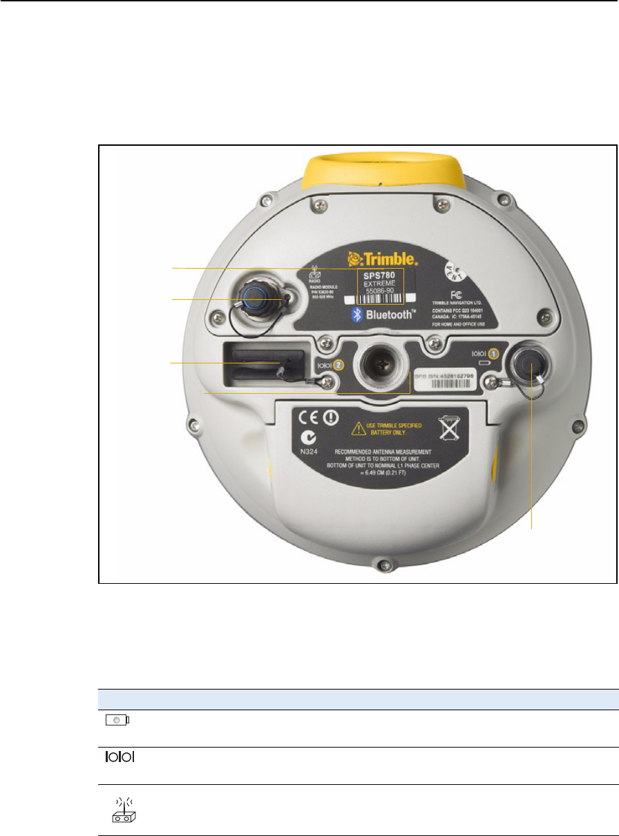
Figure 2.3 shows the lower housing of the SPS780 Smart GPS antenna. The lower
housing is the same for the SPS880, except for the identifying label. The housing
contains the two serial ports, one TNC radio antenna connector, the removable battery
compartment and the 5/8-11 threaded insert.
Figure 2.3 SPSx80 Smart GPS antenna lower housing
Each port or connector on the Smart GPS antenna is marked with an icon to indicate
its main function, as shown in Table 2.1.
Port 1 is a 7-pin 0-shell Lemo connector that supports RS-232 communications and
external power input. Port 1 has no power outputs.
Table 2.1 Receiver ports
Icon Name Connections
Port 1 Device, computer, external radio, power in
Port 2 Device, computer, external radio
RADIO Radio communications antenna
Port 1
Port 2
TNC radio
connection
Receiver identifying
label
antenna
5/8-11" threaded
insert

SPSx80 Smart GPS Antenna User Guide 21
Features and Functions 2
Port 2 is a DB-9 male connector that allows for full 9-pin RS-232 communications.
Port 2 does not support power in or out. For more information on default port settings,
see Default receiver settings, page 66. For more information on connector pinouts, see
Communication specifications, page 72.
The TNC port connector is for connecting a radio antenna to the receiver internal
radio. A whip “rubber duck” antenna is supplied with the system for units with internal
UHF or 900 MHz radios. This connector is not used if you are using an external radio
receiver. For longer range operation (to provide higher gain and to raise the antenna
higher above the ground), you can use a cable to connect an external radio antenna to
the TNC port. For more information on connecting the SPSx80 Smart GPS antenna, see
the Chapter 5, Setting up the Receiver.
Button functions
The receiver has only one button, the Power button, represented in this manual by E .
Press E to switch the receiver on or off, and to perform other functions, as described
as follows:
Note – The term “press” means to press the button and release it immediately. The term
“hold” means to press the button and hold it down for the given time.
LED behavior
The three LEDs on the front panel of the receiver indicate various operating
conditions. Generally, a lit or slowly flashing LED indicates normal operation, a LED
that is flashing quickly indicates a condition that may require attention, and an unlit
LED indicates that no operation is occurring. The following table defines each possible
LED state:
Action Power button
Turn on the receiver Press
Turn off the receiver Hold for 2 seconds
Delete the ephemeris file Hold for 15 seconds
Reset the receiver to factory defaults Hold for 15 seconds
Delete application files Hold for 30 seconds
The term … means that the LED …
Slow flash alternates on/off for 500 milliseconds.
Fast flash alternates rapidly on/off for 100 milliseconds
On is lit steady
Off is unlit

2 Features and Functions
22 SPSx80 Smart GPS Antenna User Guide
LED flash patterns
The following table details the possible flash patterns to indicate various states of
receiver operation.
Note – If a column shows “N/A”, that specific LED may or may not be on, but it is not
relevant to that particular mode.
Receiver mode Power LED
Green
Radio LED
Green
Satellite LED
Amber
Receiver OFF OFF OFF OFF
Receiver ON
Healthy power ON N/A N/A
Low power Fast flash N/A N/A
Tracking <4 SVs ON N/A Fast flash
Tracking >4 SVs ON N/A Slow flash
Logging data internally Flashes off every
3 seconds
N/A N/A
Receiving valid data packets ON Slow flash N/A
No data packets ON OFF N/A
Monitor mode ON Slow flash ON

CHAPTER
3
SPSx80 Smart GPS Antenna User Guide 23
Batteries and Power 3
In this chapter:
QExternal power
QBattery safety
QBattery performance
QCharging the Lithium-ion
batteries
QStoring the Lithium-ion battery
QDisposing of the rechargeable
Lithium-ion battery
QOperating the receiver with a
Trimble controller
The GPS receiver is powered by an internal
Lithium-ion battery, which can be detached from
the receiver for charging. The receiver can also be
connected to an external power source through
Port 1.
During measurement operations, each internal
battery typically provides about 6.6 hours of
power if using the internal RX (receive) radio and
about 4.5 hours operating as a base station using
the internal 450 MHz TX (transmit) radio. These
times vary according to the type of measurement
and the operating conditions.

3 Batteries and Power
24 SPSx80 Smart GPS Antenna User Guide
External power
The GPS receiver uses an external power source in preference to its internal batteries.
If the receiver is not connected to an external power source, or if the external power
supply fails, the internal batteries are used.
While carrying out static measurements for postprocessed computations using the
internal memory, if no external power is supplied and the internal battery is drained,
the receiver shuts down. No data is lost and when power is restored, the receiver
restarts in the same status as it was when power was lost.
Battery safety
The receiver is powered by one rechargable Lithium-ion battery. Charge and use the
battery only in strict accordance with the instructions in this chapter.
CWARNING – Do not damage the rechargeable Lithium-ion battery. A damaged battery
can cause an explosion or fire, and can result in personal injury and/or property damage.
To prevent injury or damage:
– Do not use or charge the battery if it appears to be damaged. Signs of damage include,
but are not limited to, discoloration, warping, and leaking battery fluid.
– Do not expose the battery to fire, high temperature, or direct sunlight.
– Do not immerse the battery in water.
– Do not use or store the battery inside a vehicle during hot weather.
– Do not drop or puncture the battery.
– Do not open the battery or short-circuit its contacts.
CWARNING – Avoid contact with the rechargeable Lithium-ion battery if it appears to be
leaking. Battery fluid is corrosive, and contact with it can result in personal injury and/or
property damage.
To prevent injury or damage:
– If the battery leaks, avoid contact with the battery fluid.
– If battery fluid gets into your eyes, immediately rinse your eyes with clean water and
seek medical attention. Do not rub your eyes!
– If battery fluid gets onto your skin or clothing, immediately use clean water to wash off
the battery fluid.
Battery performance
To optimize battery performance and extend battery life:
•Fully charge all new batteries before use.
•Batteries perform best when they are not used at extreme temperatures. The
receiver is designed to operate at –40 °C to +65 °C (–40 °F to +149 °F). However,
operation at temperatures of less than 0 °C (32 °F) can cause a rapid drop in
battery life.
•Do not allow a battery that is in storage to discharge to below 5 V.
SPSx80 Smart GPS Antenna User Guide 25
Batteries and Power 3
Charging the Lithium-ion batteries
CWARNING – Charge and use the rechargeable Lithium-ion battery only in strict
accordance with the instructions. Charging or using the battery in unauthorized
equipment can cause an explosion or fire, and can result in personal injury and/or
equipment damage.
To prevent injury or damage:
– Do not charge or use the battery if it appears to be damaged or leaking.
– Charge the Lithium-ion battery only in a Trimble product that is specified to charge it.
Be sure to follow all instructions that are provided with the battery charger.
– Discontinue charging a battery that gives off extreme heat or a burning odor.
– Use the battery only in Trimble equipment that is specified to use it.
– Use the battery only for its intended use and according to the instructions in the product
documentation.
The rechargeable Lithium-ion batteries are supplied partially charged.
Note – Charge the battery completely before using it for the first time. If the battery has
been stored for longer than three months, charge it before use.
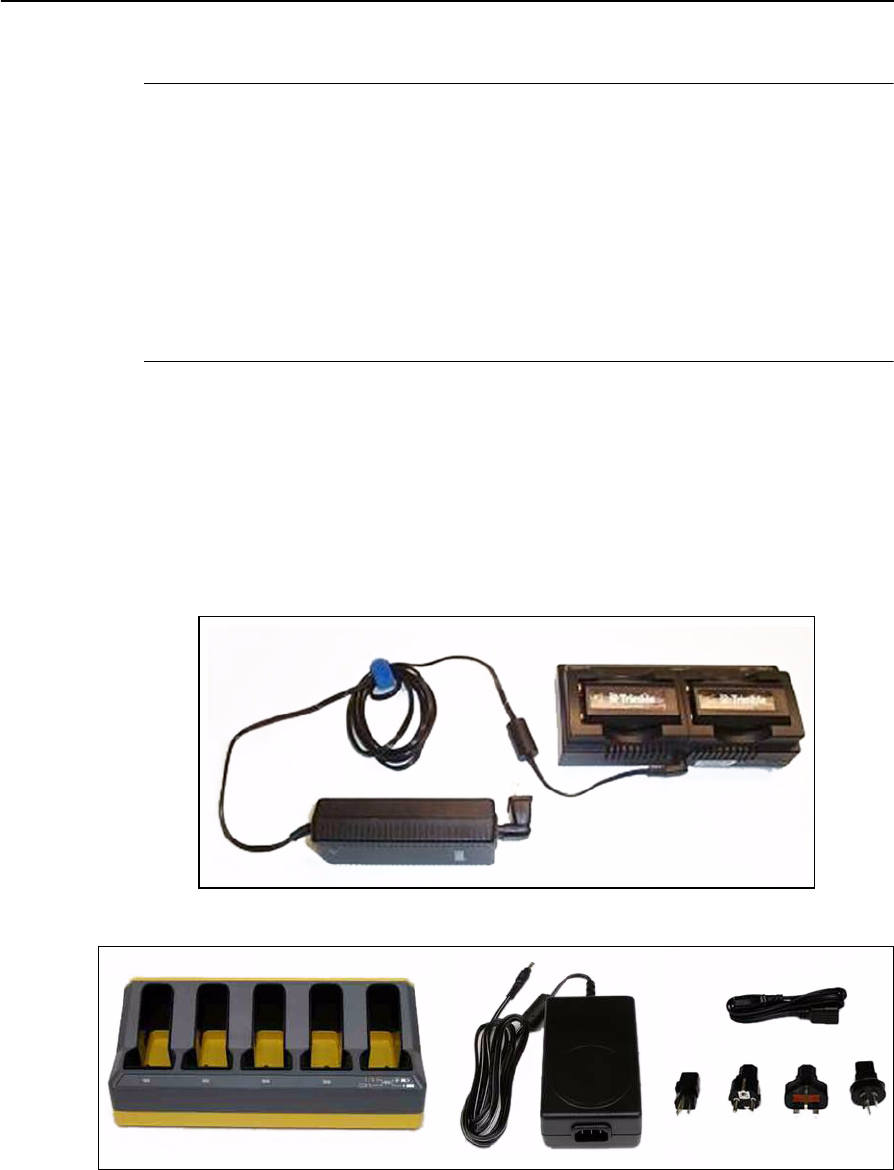
To charge the battery, first remove the battery from the receiver, and then place it in
one of the following battery chargers, which is connected to mains power:
•The dual-slot GPS battery charger (P/N 41114-00) and power supply
(P/N 48800-00):
•The five slot multi charger (P/N 49499-00) and power supply (P/N 51694):

3 Batteries and Power
26 SPSx80 Smart GPS Antenna User Guide
Storing the Lithium-ion battery
If you must store a Lithium-ion battery for long periods, make sure that it is fully
charged before it is stored, and that you charge it at least once every three months
while it is stored.
Do not allow a battery that is in storage to discharge to below 5 V. A battery that
reaches deep discharge level (5 V or less) cannot be recharged and must be replaced.
(To protect a battery that is in use from deep discharge, the receiver switches power
sources or stops drawing power when the battery pack discharges to 5.9 V.)
All batteries discharge over time when not in use, and they discharge faster in colder
temperatures. Do not store the receiver at temperatures outside the range –40 °C to
+70 °C (–40 °F to +158 °F).
Do not store the batteries in the receiver or in the external charger unless power is
applied.
Keep all batteries on continuous charge when not in use. You can keep batteries on
charge indefinitely without damage to the batteries.
Disposing of the rechargeable Lithium-ion battery
Discharge a Lithium-ion battery before disposing of it. Dispose of batteries in an
environmentally sensitive manner, and adhere to any local and national regulations
concerning battery disposal or recycling.
Operating the receiver with a Trimble controller
You can operate an SPS GPS receiver with any Trimble controller, for example, a TSC2
or TCU controller, that is running the SCS900 software. Typically, the receiver and the
controller operate from their own individual power sources. The receiver and
controller can communicate through Bluetooth wireless technology and can be
connected without a cable. However, if a cable is required, the following information
indicates which cable to use with which controller:
Controller Cable Controller connector Receiver connector
TSC2 P/N 18532 DSub9 DSub9
TCU P/N 5302007 6H (Marked “Com” on the controller
GPS holder)
DSub9
TCU
(alternative
connection)
P/N 53004007 6H (Marked “Com” on the controller
GPS holder)
7OS

CHAPTER
4
SPSx80 Smart GPS Antenna User Guide 27
Setup Guidelines 4
In this chapter:
QBase station operation guidelines
QRover operation guidelines
GPS Real-Time Kinematic (RTK) operation
provides centimeter-level accuracy by
eliminating errors that are present in the GPS
system. For all RTK operations, you require both
a base station and a rover receiver.
This chapter introduces the concepts of base
station and rover operation, provides
information to help you identify good setup
locations, describes best practices for setting up
the equipment, and outlines the precautions that
you need to take to protect the equipment.
Note – This chapter provides setup information for
all the receivers in the SPS GPS receiver family.

4 Setup Guidelines
28 SPSx80 Smart GPS Antenna User Guide
Base station operation guidelines
A base station consists of a receiver that is placed at a known (and fixed) position. The
receiver tracks the same satellites that are being tracked by the rover receiver, at the
same time that the rover is tracking them. Errors in the GPS system are monitored at
the fixed (and known) base station, and a series of position corrections are computed.
The corrections are sent through a radio link to the rover receiver, where they are used
to correct the real time positions of the rover.
Base station components
The base station has the following components:
•GPS receiver
•GPS antenna
•Base station radio
•Power supply
GPS receiver and GPS antenna
The base station GPS receiver can be one of following types:
•A Smart GPS antenna, such as the SPSx80, which incorporates a GPS receiver,
GPS antenna, power supply, and base station radio into a single compact unit. A
Smart GPS antenna can be rapidly set up on a tripod, fixed height tripod, or
T-Bar anywhere that is convenient on the jobsite.
•A Modular GPS receiver, such as the SPSx50, which incorporates a GPS receiver,
power supply, and base station radio in a single unit. The GPS antenna (and,
optionally, the base station radio antenna) is separate from the receiver. Because
the GPS antenna is separate, you can use the following optimized components:
– a geodetic antenna with large ground plane, to eliminate multipath (the
major source of GPS errors) at the base station
– a high gain or directional radio antenna, to increase broadcast range and to
provide maximum coverage
You can also place a modular GPS receiver in an easily accessible and secure
location, safe from theft and the weather, while the antennas are placed high on
a tower or building, clear of obstructions and able to deliver maximum
performance.
You can use either type of receiver in a permanent, semi-permanent, or daily quick
setup configuration. If semi-permanent or permanent operation is required, however,
the modular receiver delivers significant advantages.

SPSx80 Smart GPS Antenna User Guide 29
Setup Guidelines 4
Base station setup guidelines
For good performance, observe the following base station setup guidelines:
•Place the GPS receiver in a location on the jobsite where equal range in all
directions provides full coverage of the site. This is more important on larger
jobsites, where the broadcast range of the base station radio may limit the
operations of the GPS system.
•Place the GPS antenna in a location that has a clear line of sight to the sky in all
directions. Do not place the GPS antenna near vertical obstructions such as
buildings, deep cuttings, site vehicles, towers, or tree canopy.
•Place the GPS and radio antennas as high as practical. This minimizes
multipath from the surrounding area, and enables the radio to broadcast to the
maximum distance.
Note – The GPS antenna must have a clear line of sight to the sky at all times during
operation.
•Choose the most appropriate radio antenna for the size and footprint of the site.
The higher the gain on the antenna, the longer the range. If there is more focus
on the transmission signal, there is a reduced coverage area. A 3 db or 5 db gain
antenna provides a mix of good range and reasonable directional coverage.
•Make sure that the GPS receiver does not lose power. The GPS receiver has an
integrated battery, which has to be charged. To operate for the full day without
loss of power at the base station, provide external power. Sources of external
power include:
–AC power
– 12 V car or truck battery
– Trimble custom external battery pack
– Generator power
–Solar panel
When you use an external power supply, the integrated battery provides a
backup power supply, enabling you to maintain continuous operation through a
mains power failure.
When the GPS receiver is connected to a power source greater than 15 V, the
integrated battery is continuously charged from the connected power source.
This helps to ensure that the battery stays charged (SPS770 and SPSx50 only).
•Do not locate a GPS receiver, GPS antenna, or radio antenna within 400 meters
(about 1312 feet) of:
– a powerful radar, television, or cellular communications tower
–another transmitter
– another GPS antenna

4 Setup Guidelines
30 SPSx80 Smart GPS Antenna User Guide
Cellular phone towers can interfere with the base station radio broadcast and
can stop corrections from reaching the rover receiver. High-power signals from a
nearby radio or radar transmitter can overwhelm the receiver circuits. This does
not harm the receiver, but can prevent the receiver electronics from functioning
correctly.
Low-power transmitters, such as those in cellular phones and two-way radios,
do not interfere with receiver operations.
•Do not set up the base station directly beneath or close to overhead power lines
or electrical generation facilities. The electromagnetic fields associated with
these utilities can interfere with GPS receiver operation. Other sources of
electromagnetic interference include:
– Gasoline engines (spark plugs)
– Televisions and computer monitors
– Alternators and generators
– Electric motors
–Equipment with DC-to-AC converters
– Fluorescent lights
–Switching power supplies
•Place the GPS receivers in a protected and secure location. If the base station is
in the center of a jobsite where heavy machinery is operating, place flags around
the base station to warn operators of its existence.
•If you place the SPSx50 Modular GPS receiver or SPS770 GPS receiver in a lock
box on the jobsite to protect the receiver from theft or from the weather, shield
the lock box from direct sunlight and provide ventilation for the receiver
through an inlet and extractor fan. A receiver that has a broadcast radio
generates significant heat. Do not allow the temperature in the box to exceed
65 ºC (149 ºF).
If working in a cold climate, you may need to provide heat to the receiver. Do not
operate the receiver below –40 ºC (–40 ºF).
•Trimble recommends that, wherever possible, you keep GPS receiver equipment
dry. The receivers are designed to withstand wet weather, but keeping them dry
prolongs their life and reduces the effects of corrosion on ports and connectors.
If the equipment gets wet, use a clean dry cloth to dry the equipment, and then
leave the equipment open to the air to dry. Do not lock wet equipment in a
transport case for prolonged periods. Avoid exposing the GPS receiver to
corrosive liquids and salt water wherever possible.

SPSx80 Smart GPS Antenna User Guide 31
Setup Guidelines 4
•Trimble recommends that you install lightning protection equipment at
permanent base station locations. Equipment should include a gas capsule
lightning protector in the GPS and radio antenna feed line and appropriate
safety grounding. A static dissipater near the antennas can reduce the likelihood
of a direct lightning strike. Also protect any communications and power lines at
building entry points. For more information, contact your local Trimble dealer,
or go to the Huber and Suhner website (www.hubersuhnerinc.com).
•Trimble recommends that you use surge protection equipment on all
permanently installed equipment.
Permanent installation antenna cabling for the SPSx50 Modular GPS
receiver and SPS770 GPS receiver
Many permanent base station installations have unique cabling requirements.
Depending on the available infrastructure, you may need to mount the antenna a
considerable distance from the receiver.
The SPSx50 and SPS770 can withstand a loss of 12 dB between the GPS antenna and
the receiver. The degree of loss in a coaxial cable depends on the frequency of the
signal passing through it. Table 4.1 lists some common cable types and the maximum
length you can use before an inline amplifier for GPS frequencies is required.
Rover operation guidelines
The second part of the RTK GPS system is the rover receiver.
The rover receiver is mounted on a pole, vehicle, marine vessel, or in a backpack, and is
moved between the points that require measurement or stakeout. The rover receiver is
connected to a base station or to a source of RTK corrections such as a Virtual
Reference Station (VRS) system. The connection is provided by an integrated radio, a
Table 4.1 Maximum cable lengths
Cable type Maximum length (for use without an inline amplifier)
RG-214 30 m (100 ft)
LMR-400 70 m (230 ft)
LMR-500 85 m (280 ft)
LMR-600 106 m (350 ft)
Heliax LDF4/50 165 m (540 ft)
Heliax LDF4.5/40 225 m (740 ft)

4 Setup Guidelines
32 SPSx80 Smart GPS Antenna User Guide
cellular modem in the controller, or through an external cellular phone that is
connected to the receiver either by Bluetooth wireless technology or by means of a
cable.
The correction stream for some other positioning solutions, such as SBAS
(WAAS/EGNOS, and MSAS) and the OmniSTAR XP or HP service1, is broadcast
through geostationary satellites, and detected by the GPS antenna itself. No integrated
radio or base station is required.
Rover receiver components
The rover receiver has the following components:
•GPS receiver
•GPS antenna
•Optional integrated radio receiver and antenna for RTK operations
•Optional items for the different mounting options (see below)
In most rover applications, the receiver operates entirely from its own integrated
battery unit. On a vehicle or on a marine vessel, however, an external power supply can
be used. Use an external power supply if one is provided. The internal battery then acts
as a uninterruptible power supply, covering any external power failures.
Choose a rover receiver according to the needs of the job:
•A Smart GPS antenna, such as the SPSx80, incorporates the GPS receiver, GPS
antenna, power supply, and receive radio into a single compact unit. A Smart
GPS antenna can be rapidly set up on a pole, vehicle, or backpack. This makes it
easy to carry when you are measuring around the jobsite.
•A Modular GPS receiver, such as the SPSx50, incorporates the GPS receiver,
receive radio, and power supply into a single unit. The GPS antenna and,
optionally, the receive radio antenna, is separate from the receiver. When you
use a modular GPS receiver as a rover, you can use optimized components
placed in the best locations for your application. For example:
– A small, lightweight rover antenna can be mounted on a pole or backpack;
placed in a high, inaccessible location on a marine vessel mast or cabin; or
placed on a site vehicle roof or truck bed.
– A rubber duck radio antenna, or an external radio antenna, can be
mounted on a vehicle or vessel roof to provide maximum coverage.
A Modular GPS receiver can be placed in a location that is both easily accessible
and safe from theft and the weather. The antennas can be placed high on a
vehicle or vessel roof, clear of obstructions and able to deliver maximum
performance.
1. OmniSTAR is only available with the SPSx50 Modular GPS receiver.

SPSx80 Smart GPS Antenna User Guide 33
Setup Guidelines 4
Rover receiver setup guidelines
For good rover operation, observe the following setup guidelines:
•Place the GPS antenna in a location that has a clear line of sight to the sky in all
directions. Do not place the antenna near vertical obstructions such as
buildings, deep cuttings, site vehicles, towers, or tree canopy. GPS rovers and the
base station receive the same satellite signals from the same satellites: if you
obscure the signals at times, the system will be unable to provide RTK Fixed
positions.
•Place the GPS and radio antennas as high as possible to minimize multipath
from the surrounding area. The receiver must have a clear line of sight to the sky
at all times during operation.
•GPS satellites are constantly moving. Because you cannot measure at a specific
location now does not mean that you will not be able to measure there later,
when satellite coverage or location improves. Use GPS planning software to
identify the daily best and worst satellite coverage times for your location, and
then choose measurement times that coincide with optimal GPS performance.
This is especially important when operating in the worst GPS locations.
•The SPS770 Extreme, the SPS850 Extreme, and SPS880 Extreme can track the
GPS L2C modernization signal. Additionally, the SPS850 Extreme and SPS880
Extreme can track the GPS L5 modernization signal and the GLONASS satellite
constellation. These signals help you to get positions at the worst times of the
day and in the worst GPS locations, but do not guarantee that you will.
•To get a fixed position solution with centimeter accuracy, initialize the rover
receiver. For initialization to take place, the receiver must track at least five
satellites that the base station is also tracking. In a dual-satellite constellation
operation, for example, GPS and GLONASS, the receiver must track at least six
satellites.
•To maintain a fixed position solution, the rover must continuously track at least
four satellites that the base station is also tracking. In a dual-satellite
constellation operation, for example, GPS and GLONASS, the receiver must
track at least five satellites.The radio link between the base and rover receivers
must also be maintained.
•Loss of the satellite signals or loss of the radio link results in a loss of centimeter
position accuracy. From Fixed, the receiver changes to Float or Autonomous
mode:
– In Float mode, the rover has connection to the base station through a radio,
but has not yet initialized.
– In Autonomous mode, the rover has lost radio contact with the base
station receiver, and is working by itself with the available GPS signals.
4 Setup Guidelines
34 SPSx80 Smart GPS Antenna User Guide
•On a vehicle or marine vessel, place the GPS antenna in a location as free from
shock and vibration as possible. For the modular receivers, a single magnetic
mount is normally sufficient to hold the antenna in a suitable location, whereas
for the larger smart antenna, a triple magnetic mount is normally
recommended. Good alternatives include a 5/8" thread bolt in a suitable
location on the roof bars, or a door-mounted pole bracket.
CCAUTION – The SPS880 Extreme is not suited to on-vehicle operation where it will be
subject to heavy vibration, that is, operation in rough ungraded terrain. Use in these
conditions can damage the SPS880 Extreme.
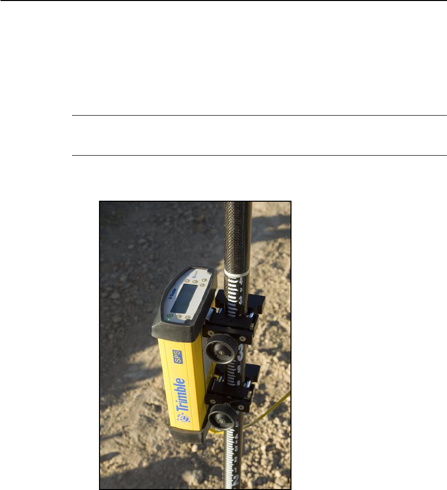
•To mount the modular receiver on a pole, use two pole mounting brackets and a
second tripod clip (P/N 571 204 300). See Figure 4.1.
Figure 4.1 Rod mount for modular receiver
To mount the modular receiver on a marine vessel, use the receiver bracket
(P/N 56830-00). For marine moving base and heading applications, use the
receiver bracket to mount two receivers together.

SPSx80 Smart GPS Antenna User Guide 35
Setup Guidelines 4
•Make sure that the rover receiver does not lose power. An SPSx50 is typically
powered by its internal battery. You cannot change the battery, but the charge
typically lasts for longer than a working day. The batteries in the SPSx80 can be
changed when flat. (See Chapter 3, Batteries and Power). If you do not use the
rover receiver very often, ensure that it is charged at least every three months.
For vehicle operation or marine vessel operation, Trimble recommends that you
use an external power source so that the internal battery can be saved for times
when the receiver is being used off the vehicle or vessel.
•Do not locate the receiver or antenna within 400 meters (1312 ft) of powerful
radar, television, cellular communications tower, or other transmitters or GPS
antennas. Low-power transmitters, such as those in cellular phones and
two-way radios, normally do not interfere with receiver operations. Cellular
towers can interfere with the radio and can interfere with GPS signals entering
the receiver. High-power signals from a nearby radio or radar transmitter can
overwhelm the receiver circuits. This does not harm the receiver, but it can
prevent the receiver electronics from functioning correctly.
•Do not use the rover receiver directly beneath or close to overhead power lines
or electrical generation facilities. The electromagnetic fields associated with
these utilities can interfere with GPS receiver operation. Other sources of
electromagnetic interference include:
– gasoline engines (spark plugs)
– televisions and computer monitors
– alternators and generators
– electric motors
–equipment with DC-to-AC converters
– fluorescent lights
– switching power supplies
•Trimble recommends that, wherever possible, all GPS receiver equipment is
protected from rain or water. Although, the receivers are designed to withstand
all wet weather conditions, keeping the receivers dry prolongs the life of the
equipment and reduces the effects of corrosion on ports and connectors. If the
equipment gets wet, use a clean dry cloth to dry the equipment, and then leave
the equipment open to the air to dry. Do not lock wet equipment in a transport
case for prolonged periods. Wherever possible, avoid exposing the GPS receiver
to corrosive liquids and salt water.
•If you are using the rover receiver in open spaces, Trimble recommends that you
stop work during electrical storms where the risk of lightning strike is high.
•Where cables are involved, Trimble recommends that you use cable ties to
secure the cables to the rod or other equipment to avoid inadvertent snagging
while moving about the jobsite. Be careful not to kink, twist, or unnecessarily
extend cables, and avoid trapping them in vehicle doors or windows. Damage to
cables can reduce the performance of GPS equipment.

4 Setup Guidelines
36 SPSx80 Smart GPS Antenna User Guide
Internal radio setup for rover operations
The internal radio of the SPS GPS receiver is delivered with the transmit (Tx) radio
frequencies preprogrammed into the receiver. To add receive (Rx) radio frequencies to
450 MHz radios, use the WinFlash utility (see Appendix C, Adding Internal Radio
Frequencies). Radio frequences cannot be added to the 900 MHz radios.
Once the radio frequencies are configured, use the controller or receiver to select
channel frequencies during base station or rover setup operations.
Cellular modem and external radio
Instead of the internal radio, you can use a cellular modem or an external radio as your
data communications link.
To connect a cellular modem to an SPSx80 Smart GPS antenna, you need the following:
•SPSx80 Smart GPS antenna.
•One of the following:
– TSC2 controller with CompactFlash card cellular modem, for example, a
Audiovox modem card
– Cellular modem or a cellular phone that can transmit data
•Serial (cellphone to DB9) cable (supplied with the cellular modem or phone).
•Port 2 of the SPSx80 supports full RS-232 protocol, and should function properly
with most cellular phone cables. Some cellular units may require custom
cabling.
Alternatively, the receiver also supports a cable-free Bluetooth connection with
Bluetooth-enabled cell phones.
For more information on using a cellular modem as a data link, refer to the SCS900 Site
Controller Software Getting Started Guide and SCS900 Site Controller Software Office
Guide.

CHAPTER
5
SPSx80 Smart GPS Antenna User Guide 37
Setting up the Receiver 5
In this chapter:
QConnecting the receiver to
external devices
QCommon ways to set up a base
station
QCommon ways to set up a rover
receiver
In this chapter, recommendations for setting up
the receiver as a base station or for rover
operations are provided. The recommendations
cover a variety of common use scenarios.
Note – This chapter provides setup information for
all the receivers in the SPS GPS receiver family.

5 Setting up the Receiver
38 SPSx80 Smart GPS Antenna User Guide
Connecting the receiver to external devices
You can connect an SPSx80 to the following devices:
•a Trimble controller running Trimble SCS900 Site Controller software
•an external radio-modem
Trimble controller with SCS900 Site Controller software
To connect a Trimble controller that is running the SCS900 Site Controller software to
an SPS GPS receiver, use Bluetooth wireless technology ( for all except the SPS770 GPS
receiver) or a serial cable. Table 5.1 shows how to connect the cables for each
combination of SPS GPS receiver and Trimble controller.
Table 5.1 Connecting to a Trimble controller running the SCS900 Site Controller software
Use this cable
connector …
and connect the
cable to …
Cable part number
To connect a SPSx50 Modular GPS receiver to a …
TSC2 DB9 TSC2 32960
Lemo SPSx50
TCU 6-pin Hirose TCU 53004007
Lemo SPSx50
TSCe™ Lemo TSCe 31288-xx
Lemo SPSx50 This cable is available in different lengths. The
-xx indicates the length of the cable, in meters.
ACU 4-pin Hirose ACU 44147
Lemo SPSx50
To connect a SPS770 Modular GPS receiver to a …
TSC2 DB9 TSC2 32960
Lemo (Port 1) SPS770
TCU 6-pin Hirose TCU 53004007
Lemo (Port 1) SPS770
TSCe Lemo TSCe 31288-xx
Lemo (Port 1) SPS770 This cable is available in different lengths. The
-xx indicates the length of the cable, in meters.
ACU 4-pin Hirose ACU 44147
Lemo SPS770
To connect a SPSx80 Smart GPS antenna to a …
TSC2 DB9 TSC2 32960
Lemo (Port 1) SPSx80
TCU 6-pin Hirose TCU 53004007
Lemo (Port 1) SPSx80
TSCe Lemo TSCe 31288-xx
Lemo (Port 1) SPSx80 This cable is available in different lengths. The
-xx indicates the length of the cable, in meters.

SPSx80 Smart GPS Antenna User Guide 39
Setting up the Receiver 5
External radio-modems
The most common data link for Real-Time Kinematic (RTK) operation is a radio. The
SPSx80 is available with the following internal radios:
•410 – 430 MHz (Tx/Rx, Rx only, or Tx only)
•430 – 450 MHz (Tx/Rx, Rx only, or Tx only)
•450 – 470 MHz (Tx/Rx, Rx only, or Tx only)
•900 MHz (Rx only)
Note – “Tx” indicates that the radio transmits corrections. “Rx” indicates that the receiver
receives corrections. “Tx/Rx” indicates that the radio both transmits and receives
corrections.
If the SPSx80 does not have an internal transmit radio, or you want to connect to a
higher powered external transmit radio or cellular modem, use the DB9 port, the Lemo
port, or Bluetooth wireless technology.
The SPS780 supports the following Trimble base radios:
•TRIMMARK 3
•Trimble SNB900
•Trimble PDL450
•Trimble HPB450
The receiver also supports third-party transparent radios and third-party cellular
modems.
To use an external radio with the SPSx80, you need an external power source for the
radio—except for the SNB900 radio, which contains an internal battery. To configure
the radio modem separately, use the external radio’s configuration program, or display
and keypad.
ACU 4-pin Hirose ACU 44147
Lemo SPSx80
Table 5.1 Connecting to a Trimble controller running the SCS900 Site Controller software (cont)
Use this cable
connector …
and connect the
cable to …
Cable part number

5 Setting up the Receiver
40 SPSx80 Smart GPS Antenna User Guide
Common ways to set up a base station
You can set up a base station in different ways depending on the application, coverage
area, degree of permanence versus mobility, and available infrastructure. Before you set
up a base station, please read Chapter 4, Setup Guidelines.
Setting up a base station for permanent or semi-permanent installation
For construction applications, where machine and site positioning operations using
GPS will be carried out over a long time (weeks, months, or years), ensure that you
choose the base station location carefully.
A semi-permanent or permanent base station helps to eliminate the types of error that
can result from repeated daily setups, and ensures that you always use the GPS
antenna at the exact original location. The requirement for a permanent base station
setup increases as more receivers that use the base station as a source of corrections,
increases the cost of any base station downtime.
On the largest jobsites, and on those that remain operational for the longest time, a
permanent or semi-permanent installation is a popular solution. An SPSx50 or SPS770
GPS receiver is typically used as the base station, located in a site office or trailer where
it is easy to access (to check or configure), and where it is secure from theft and the
weather. The GPS and radio antennas are normally mounted on a permanent structure
on the roof of the building, where they are high and clear from obstructions and where
the radio antenna can provide the maximum range of operation.
The GPS antenna most commonly used is the Trimble Zephyr Geodetic™ Model 2.
This antenna has a large ground plane that eliminates multipath, providing the best
GPS performance at the base location. The antennas are connected to the receiver by
high quality RF cables.
The receiver is connected to a permanent power supply (mains or generator power).
The internal battery of the receiver is always being charged, and acts as an
uninterruptible power supply if there is a power failure. In some cases, the receiver may
also be connected by an Ethernet cable to the Internet, so that it can be monitored and
configured from a remote location, and can warn an administrator by e-mail or text
message if there is a change to the configuration. In these situations, the receiver can
transmit GPS RTK corrections to a remote radio or receiver over the Internet, for
rebroadcast requirements, without using repeaters.

SPSx80 Smart GPS Antenna User Guide 41
Setting up the Receiver 5
Figure 5.1 SPSx50 receiver permanent installation
Setting up a base station for daily site use: T-Bar
For construction applications where a daily setup and takedown of equipment is
required for security reasons, Trimble recommends that you use a T-Bar setup.
The T-Bar consists of a post mounted in concrete (so it cannot move), which has a
solid metal T-Bar mounted to it to provide lateral separation between the GPS antenna
and radio antenna. The T piece of the T-Bar has a vertical rod at each end. Each end
terminates in a 5/8"×11 thread to which the antennas can be mounted. Trimble
recommends that one end is clearly marked GPS and the other end is clearly marked
Radio so that at each daily setup, the GPS and radio antennas are mounted at the
same location. Switching antennas by mistake introduces a position error in all
resulting measurements. You can buy the parts you need to make a T-Bar from any
reputable hardware store. Make certain that the T-Bar cannot rotate after
construction. Rotation of the T-Bar can introduce a position error into all subsequent
measurements.
On the upright post, mount either a bracket (to which the GPS receiver can be
mounted), or a well-ventilated lockbox (in which the GPS receiver itself can be
secured).
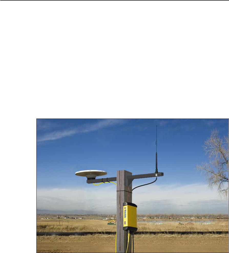
5 Setting up the Receiver
42 SPSx80 Smart GPS Antenna User Guide
Each day, mount the GPS antenna on the GPS end of the T-Bar and the radio antenna
on the Radio end of the T-Bar. Connect the antennas to the receiver using the
appropriate cables.The receiver uses its own integrated battery, or an external 12 V
battery through the 12 V crocodile clips cable that are provided with the receiver. If you
choose to use AC power, remember that the heat generated by the charging process
and the radio transmitter increases the need for good ventilation around the receiver.
In such scenarios, an SPSx80 Smart GPS antenna is also often used. Simply mount the
SPSx80 on the T-Bar, and optionally connect to an external battery or radio unit.
Advantages
Use of a T-Bar setup ensures that the base station is set up with exactly the same
position and height every day. This helps eliminate the errors typically associated with
daily tripod setup. For example, wrong antenna height, base not set up over the point,
base set up in the wrong location.
Figure 5.2 System set up on a T-bar showing an external radio antenna to gain longer
range
Setting up a mobile base station: Tripod and fixed height tripod
If you are repeatedly moving between jobsites, or if you are visiting a jobsite for the first
time before a T-Bar or similar setup can be established, Trimble recommends that you
use either a tripod and tribrach setup, or a fixed height tripod.
The fixed height tripod is quicker and easier to set up over a control point. Take great
care to ensure that the GPS antenna is set up accurately over the control point, and
that the GPS antenna height is measured accurately, in the right way (vertical or slope
GPS
Radio

SPSx80 Smart GPS Antenna User Guide 43
Setting up the Receiver 5
height) to the right location on the antenna (base of antenna or to a specified location
on the antenna). When you start the rover receiver, it is extremely important to check
in, at one or more known locations, to check for possible position or height errors.
Checking in at a known location is good practice and can avoid costly errors caused by
a bad setup.
Typically, the tripod and fixed height tripod methods do not give significant height
clearance above the ground, and can reduce the range of operation caused by radio
limitations.
Tripod and tribrach setup
In the tripod setup, the tripod is located over the control point, and the tribrach and
tribrach adaptor is mounted on the tripod and centered over the point.
1. Mount the GPS antenna on the tribrach adaptor.
– If you are using a SPSx80 Smart GPS antenna, use the 25 cm spacer rod
provided with the SPSx80 base station accessory kit. This allows the radio
antenna in the receiver to clear the head of the tripod.
2. Clip the GPS receiver to the tripod (SPSx50 and SPS770 only).
3. Connect the GPS antenna to the receiver using the appropriate cable (SPSx50
and SPS770 only).
4. If necessary, connect the GPS receiver to an external 12 V power supply. Use the
crocodile clip cable or the Trimble custom power pack.
Figure 5.3 Tripod and tribrach setup for the SPSx50 and the SPSx80
SPSx80 with an internal 450 MHz
TX radio
SPSx50 with an external
high-gain antenna
SPSx50 with a low-gain “rubber
duck” antenna
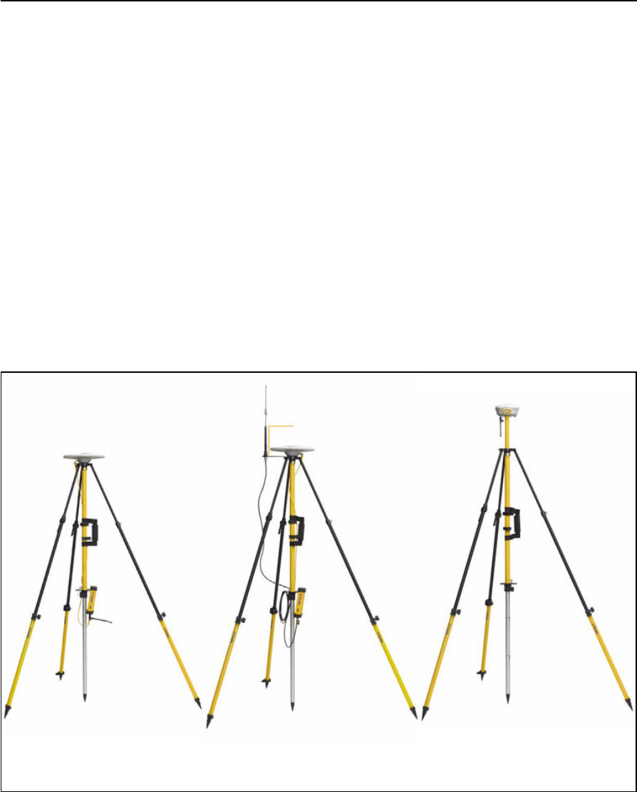
5 Setting up the Receiver
44 SPSx80 Smart GPS Antenna User Guide
Fixed height tripod setup
A fixed height tripod setup is similar to a tripod setup, but is simplified by the central
leg of the tripod, that is placed directly on the control point. If the central leg is leveled
accurately, the fixed height tripod is quick and easy to set up, and provides an accurate
way to measure the true antenna height.
1. Set up the tripod over the control point.
2. Attach the GPS antenna to the head of the tripod.
3. If using an external high-gain radio antenna, mount the radio antenna to the
radio antenna bracket that is attached to the head of the tripod (beneath the
GPS antenna). See Figure 5.4.
4. If using the SPSx50 Modular GPS receiver, hook the receiver to the center leg of
the tripod, using the tripod clip.
5. If using the SPSx80 Smart GPS antenna, you can mount the antenna using the
25 cm spacer rod (supplied with the SPSx80 Base Station Accessory kit) so that
the radio antenna clears the head of the tripod.
Figure 5.4 Fixed height tripod setup for the SPSx50 and SPSx80
SPSx80 with an internal 450 MHz
TX radio on a fixed height tripod
SPSx50 with an external high-
gain radio antenna
SPSx50 with a low-gain “rubber
duck” antenna
Radio antenna bracket

SPSx80 Smart GPS Antenna User Guide 45
Setting up the Receiver 5
Common ways to set up a rover receiver
You can set up a rover receiver in different ways depending on the application. The
components that make up a rover receiver are:
•GPS receiver
•GPS antenna
•controller/computer
•rod mounting equipment, including a rod, receiver bracket, and controller
bracket
•vehicle mounting equipment, including a suction cup and ball joint, extension
arm, controller bracket, magnetic antenna mount, and necessary cables.
•backpack equipment, including backpack and antenna-mounting rod
•marine vessel mounting equipment, including receiver bracket, cables, antenna,
and radio antenna brackets.
Setting up the rover receiver on a jobsite vehicle
CCAUTION – This following rover setup is suited only to offroad (jobsite) vehicle use. Do
not use this method on a vehicle that is driven at speed or in traffic.
1. Do one of the following, depending on your receiver:
– SPSx50 or SPS770: Mount the GPS antenna for the receiver on the roof of
the vehicle. Use a single magnetic mount or a 5/8"×11 thread bolt attached
to the roof bars. Run the GPS antenna cable for the receiver into the vehicle
either through a rubber grommet in the roof, or through the passenger door
window, which needs to be left slightly open during operation.
– SPSx80: Mount the receiver on the roof of the vehicle. Use a triple magnetic
mount or a 5/8"×11 thread bolt attached to the roof bars.
2. Place and secure the GPS receiver in a convenient location in the vehicle.
The GPS receiver can be controlled through the controller connected using
Bluetooth wireless technology (SPSx50 or SPSx80) or a cable connected to a port
on the receiver (SPS770).
The receiver needs to be accessed only to turn it on at the start of each
measurement session. It may be more convenient if the SPSx50 is placed in a
location where the vehicle operator can see the keypad and display, to monitor
receiver status and to configure settings as required. Most receiver capability
can be controlled using the SCS900 Site Controller software.
3. Attach the suction cup to the front windscreen, dashboard, or other convenient
location in the vehicle, making sure that it does not obstruct the driver’s view.

5 Setting up the Receiver
46 SPSx80 Smart GPS Antenna User Guide
4. Attach the RAM extension arm to the suction cup, and the controller bracket to
the RAM extension arm.
5. Lock the controller into the controller bracket and then adjust the bracket until
the controller is in the most convenient location. Make sure that the controller
does not restrict visibility through the front windscreen during vehicle use.
6. Lock the brackets so that the controller is held securely. If required, connect
either the GPS receiver or the controller to an in-vehicle power supply as
needed.
Figure 5.5 Configuring SPSx50 from the cab. A Zephyr Model 2 antenna is mounted on
the roof

SPSx80 Smart GPS Antenna User Guide 47
Setting up the Receiver 5
Setting up the rover receiver on a rod
For rod-based operation, mount the SPSx50 Modular
GPS receiver as follows:
1. Mount the two rod brackets on the rod.
2. Tighten the top bracket, making sure that it is at
a convenient height for the receiver.
3. Place the receiver in the slot in the rod bracket,
and secure with the tripod clip.
4. Move the lower rod bracket down until it is over
the second tripod clip on the receiver, and then
tighten the rod bracket onto the rod. The
receiver is held in place between the two
brackets.
5. Insert the controller into the controller bracket
as shown opposite.
6. Use the 5/8" thread to attach the GPS antenna to
the top of the rod.
7. Use the GPS antenna cable to connect GPS
antenna to the receiver.
For rod-based operation, mount the SPSx80 Smart GPS antenna as follows:
1. Mount the receiver on the top of the rod using the 5/8"×11 thread in the base of
the SPSx80.
2. Insert the controller into the controller bracket.
3. The SPSx80 and controller communicates through Bluetooth wireless
technology. However, if a cable is required, connect the cable between the
controller and receiver (see Figure 5.6 through Figure 5.7).
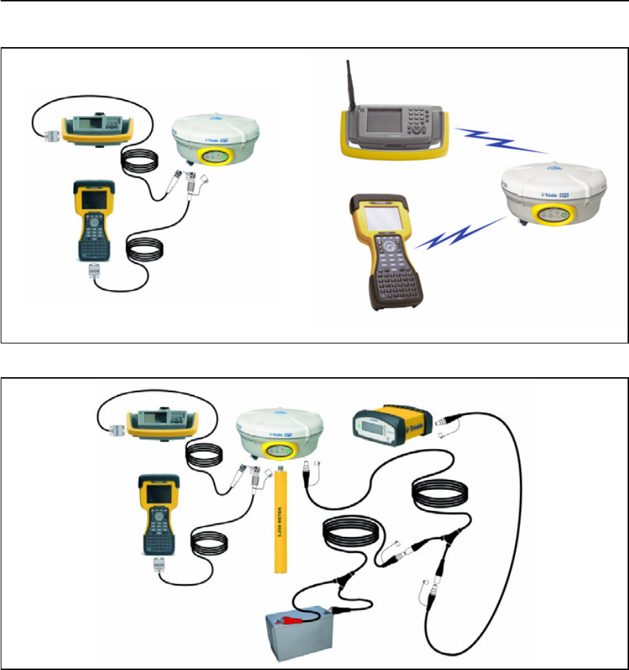
5 Setting up the Receiver
48 SPSx80 Smart GPS Antenna User Guide
Figure 5.6 Connections for a rover SPSx80 setup, a TSC2 or TCU controller, and a 450 Mhz base station
Figure 5.7 Cabled connections for an SPSx80 setup, a TSC2 or TCU controller, and a 900 Mhz base station
(with external power)
Setting up a rover receiver on a belt or in a backpack
If you prefer to work free of the weight of a pole, you can mount the rover receiver on a
belt (SPS770 or SPSx50 only) or carry it in/on a backpack (all receivers). When you
wear the receiver on a belt, ensure that the display is always visible so that you can
easily check the status of the receiver. If you carry the receiver in a backpack, use an
external radio antenna mount to allow for optimal radio signal reception. If you use a
low gain antenna mounted directly on the receiver in a backpack, it may affect the
radio signal reception and reduce the likelihood of obtaining an RTK Fixed solution.
Cabled connections Bluetooth connections
P/N 53002007
P/N 32960
<<diagram being updated>>
P/N 53002007
P/N 32960
P/N 312888-02
P/N 46125-00

SPSx80 Smart GPS Antenna User Guide 49
Setting up the Receiver 5

5 Setting up the Receiver
50 SPSx80 Smart GPS Antenna User Guide

CHAPTER
6
SPSx80 Smart GPS Antenna User Guide 51
Configuring the Receiver Settings 6
In this chapter:
QUsing the SCS900 Site Controller
software to configure the base
station, the rover, and the radios
QConfiguring the receiver to log
data for postprocessing
QConfiguring the receiver in real
time
QConfiguring the receiver using
application files
QCreating and editing the
configuration files that control
the receiver
You can configure the SPS GPS receiver family in
a variety of ways. This chapter describes the
different configuration methods, and explains
when and why each method is used.
The SPS770 and SPSx80 receivers have no
controls for changing settings. To configure these
receivers:
•In real time, use external software such as
the HYDROpro™ software, or the GPS
Configurator or WinFlash utility.
•In an application file, use the Configuration
Toolbox utility.
The SCS900 Site Controller software is likely to be
your main tool to set up and operate the receiver
on a daily basis. All necessary field configurations
are handled through the SCS900 software
running on a TSC2 or TCU controller. For more
information, refer to the Trimble SCS900 Site
Controller Software Getting Started Guide or the
Trimble SCS900 Site Controller Software Office
Guide.
The external software detailed in this chapter is
primarily used to update the receiver firmware
and to configure upgrades or radio channels.
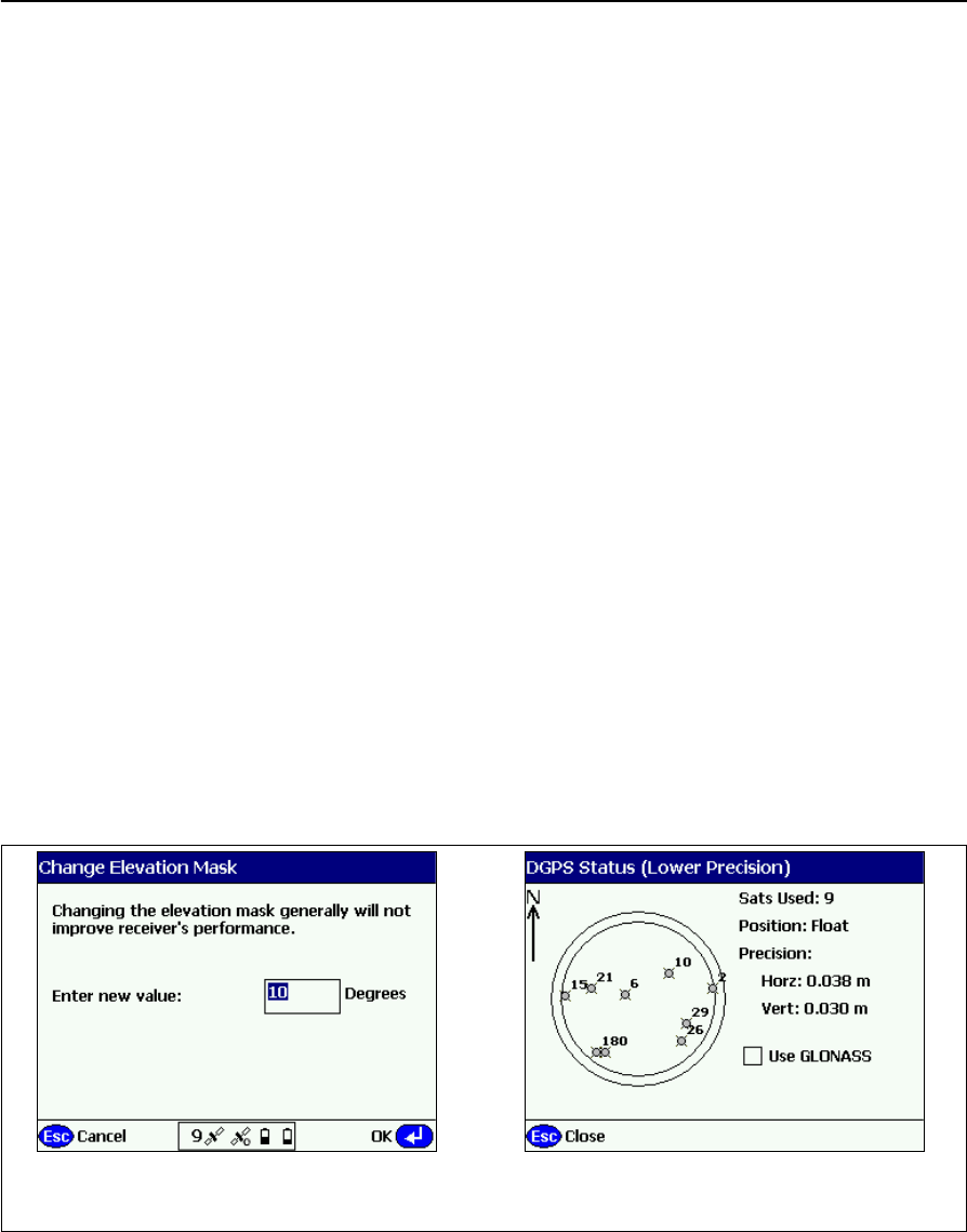
6 Configuring the Receiver Settings
52 SPSx80 Smart GPS Antenna User Guide
Using the SCS900 Site Controller software to configure the
base station, the rover, and the radios
As part of a total system solution for construction applications, the SPS GPS receivers
are operated by a TSCe, ACU, TCU, or TSC2 controller running the SCS900 Site
Controller software. The SCS900 Site Controller software provides the tools to
configure and start the GPS receiver in the modes used by the SCS900 system: Base
Station, RTK Rover, DGPS Rover, OmniSTAR rover, SBAS Rover (using WAAS/EGNOS
and MSAS). Wizards help you through the process and, where possible, assign suitable
default operational parameters to the system. This eliminates the need for an operator
to know how to configure the receiver with the right settings.
The SCS900 Site Controller software manages:
•the radio, whether internal or external
•all cellular communications components, such as modems and cellphones
•the use of the Bluetooth wireless technology
The software also scans communication ports on the receiver to identify connected
devices. If the software cannot automatically identify the connected component, for
example, a GPS antenna, it offers options (often with graphics) to help you manually
select the correct component.
The SCS900 Site Controller software allows you to set operational tolerances and
settings (such as those shown below), which must be achieved before measurements
can be accepted. When outside of these tolerances, the SCS900 Site Controller
software warns you through on-screen messages or indications, and the non-
automatic acceptance of recorded positions. To set operational tolerances, go to the
the Settings menu in the SCS900 Site Controller software.
Example 2: Use the Sky Plot screen toExample 1: From the Sky Plot screen, press
Ctrl+M to open this screen and change the angle
below which the receiver will not track satellites
set if the receiver will track GLONASS satellites

SPSx80 Smart GPS Antenna User Guide 53
Configuring the Receiver Settings 6
Configuring the receiver to log data for postprocessing
The SPS GPS receivers do not come equipped with the Data Logging option. The
receivers can have this added either at the time of purchase, or at a later date as an
option. With the Data Logging option enabled, the receiver has available memory that
facilitates the collection of GPS observations over a period of time, and that can be
used with GPS postprocessing software such as the Trimble Geomatics Office™ for the
computation of control networks and baselines.
Note – The SCS900 system does not support postprocessed applications. Trimble
recommends that you use either the front panel keypad and display, the Web User
Interface, or (SPS770, SPSx80 only) the GPS Configurator software to configure the receiver
for postprocessed measurement sessions.
Configuring the receiver in real time
The SPS770 and SPSx80 receivers can be configured in real time by the GPS
Configurator software.
When you configure the receiver in real time, you use the software to specify which
settings you want to change. When you apply the changes, the receiver settings change
immediately.
Any changes that you apply to the receiver are reflected in the current application file,
which is always present in the receiver. The current application file always records the
most recent configuration, so if you apply further changes (either in real time or using
an application file) the current file is updated and there is no record of the changes that
you applied originally.
Configuring the receiver using application files
An application file contains information for configuring a receiver. To configure a
receiver using an application file, you need to create the application file, transfer it to
the receiver and then apply the file’s settings. The GPS Configurator software does this
automatically when you work with configuration files.
Overview
An application file is organized into records. Each record stores configuration
information for a particular area of receiver operation. Application files can include the
following records:
•File Storage
•General Controls
•Serial Port Baud Rate/Format
•Reference Position

6 Configuring the Receiver Settings
54 SPSx80 Smart GPS Antenna User Guide
•Logging Rate
•SV Enable/Disable
•Output Message
•Antenna
•Device Control
•Static/Kinematic
•Input Message
An application file does not have to contain all of these records. When you apply an
application file, any option that is not included in the records in the file remains at its
current setting. For example, if you apply an application file that only specifies the
elevation mask to use, all other settings remain as they were before the application file
was applied.
You can store up to twenty different application files in the receiver. You can apply an
application file’s settings at the time it is transferred to the receiver, or at any time
afterwards.
Special application files
The receiver has three special application files, which control important aspects of the
receiver’s configuration.
Default application file
The default application file (Default.cfg) contains the original receiver configuration,
and cannot be changed. This file configures the receiver after it is reset. You can reset
the receiver by pressing E for at least 15 seconds, or by using the reset option in the
GPS Configurator software.
For more information, see Chapter 8, Default Settings.
Although you cannot change or delete the default application file, you can use a power
up application file to override any or all of the default settings.
Current application file
The current application file (Current.cfg) reflects the current receiver configuration.
Whenever you change the receiver’s configuration, either in real time or by applying an
application file, the current file changes to match the new configuration.
You cannot delete the current file or change it directly, but every change to the
receiver’s current configuration is applied to the current file as well.
When you switch off the receiver then turn it on again, all the settings from the current
application file are applied, so you do not lose any changes that you have made. The
only exceptions are the following logging parameters:
•Logging rate

SPSx80 Smart GPS Antenna User Guide 55
Configuring the Receiver Settings 6
•Position rate
•Elevation mask
These parameters are always reset to the factory default values whenever the receiver
is switched off.
Power Up application file
The power up application file (Power_up.cfg) is used to set the receiver to a specific
configuration any time the unit is powered up.
In this file, you can specify that the receiver is reset to defaults before the power up
settings are applied. This ensures that restarting the receiver always resets it to factory
defaults prior to applying the power up application file.
Alternatively, you can specify that the power up settings are applied immediately after
the current application file’s settings have been applied. Restarting the receiver results
in a configuration that uses your default settings for the options you define in the
power up file, but the current settings for all other options.
By default, there is no power_up application file on the receiver. To use a power up
application file, you must create and save a power_up application file in the GPS
Configurator software. If you save this file to disk, the file is called power_up.cfg. The
extension .cfg is used, by convention, to identify application files on the office
computer. When you transfer this file to the receiver, the file is saved on the receiver as
power_up, and becomes the new power up file.
The power up file is the only special application file that you can overwrite or delete
from the receiver.
Applying application files
An application file’s settings do not affect the receiver’s configuration until you apply
the application file. You can do this at the same time that you save the file.
Alternatively, you can save the file on the computer or in the receiver, then open it later
and apply its settings.
Storing application files
You can store application files that you create in the GPS Configurator software on the
receiver and on the computer. For example, each file can represent a different user
sharing the same receiver, or a particular mode of operation. Saving application files on
your computer as well as in your receiver is optional, but it is useful because:
•it gives you a permanent copy of the settings you have sent to a receiver, for
audit or your own reference.
•you can use the same file to configure multiple receivers identically.
•you can use an existing application file as a template to create other application
files with similar settings.

6 Configuring the Receiver Settings
56 SPSx80 Smart GPS Antenna User Guide
Naming application files
The application filename in the office computer and in the receiver are always the
same. This makes it easier to recognize and keep track of your application files.
When you change the name of the application file in the receiver, this changes the
application filename on your computer. When you transfer an application file from the
receiver and save it to the computer, the system renames the file to match the internal
receiver file. However, if you use Windows Explorer, for example, to change the .cfg
filename on the computer, this does not change the internal receiver filename. This
means that the GPS receiver does not recognize the change to the filename on the
computer.
Creating and editing the configuration files that control the
receiver
The Configuration Toolbox software enables you to create and edit GPS receiver
configuration files. The settings in these files control the operation of the GPS receiver.
The GPS receiver configuration file can then be copied and sent to the receiver.
You can also create a file, called an application file or appfile, (*.cfg), which contains all
the receiver settings necessary for a particular job or application. Application files can
be stored on both the receiver and computer. Multiple files can be maintained to
represent multiple users sharing a device and/or multiple modes of operation. You can
also save files to audit the operating settings of a receiver.
For applications requiring real-time positions in any coordinate system other than
WGS-84, you need the Configuration Toolbox software to define and transfer the
necessary coordinate system and transformation parameters.
A maximum of ten files can be stored in the receiver. This includes the files default.cfg
and current.cfg, which always reside in the receiver.
Note – If you use the SCS900 Site Controller software in the field, you do not need to use the
Configuration Toolbox software to set up the transformation parameters. This is done
through the Site Calibration process in the SCS900 software.
Installing the Configuration Toolbox software
You can install the Configuration Toolbox software from the Trimble SPS GPS Receiver
CD that is shipped with your receiver, or download it from the Trimble website.
The Configuration Toolbox software requires one serial port dedicated to receiver
communications.
Installing new versions of the Configuration Toolbox software updates the Coordinate
System Library. If you have calibrated sites stored on your computer, save them as
receiver configuration files. This ensures that the coordinate system information for
particular sites are not overwritten.
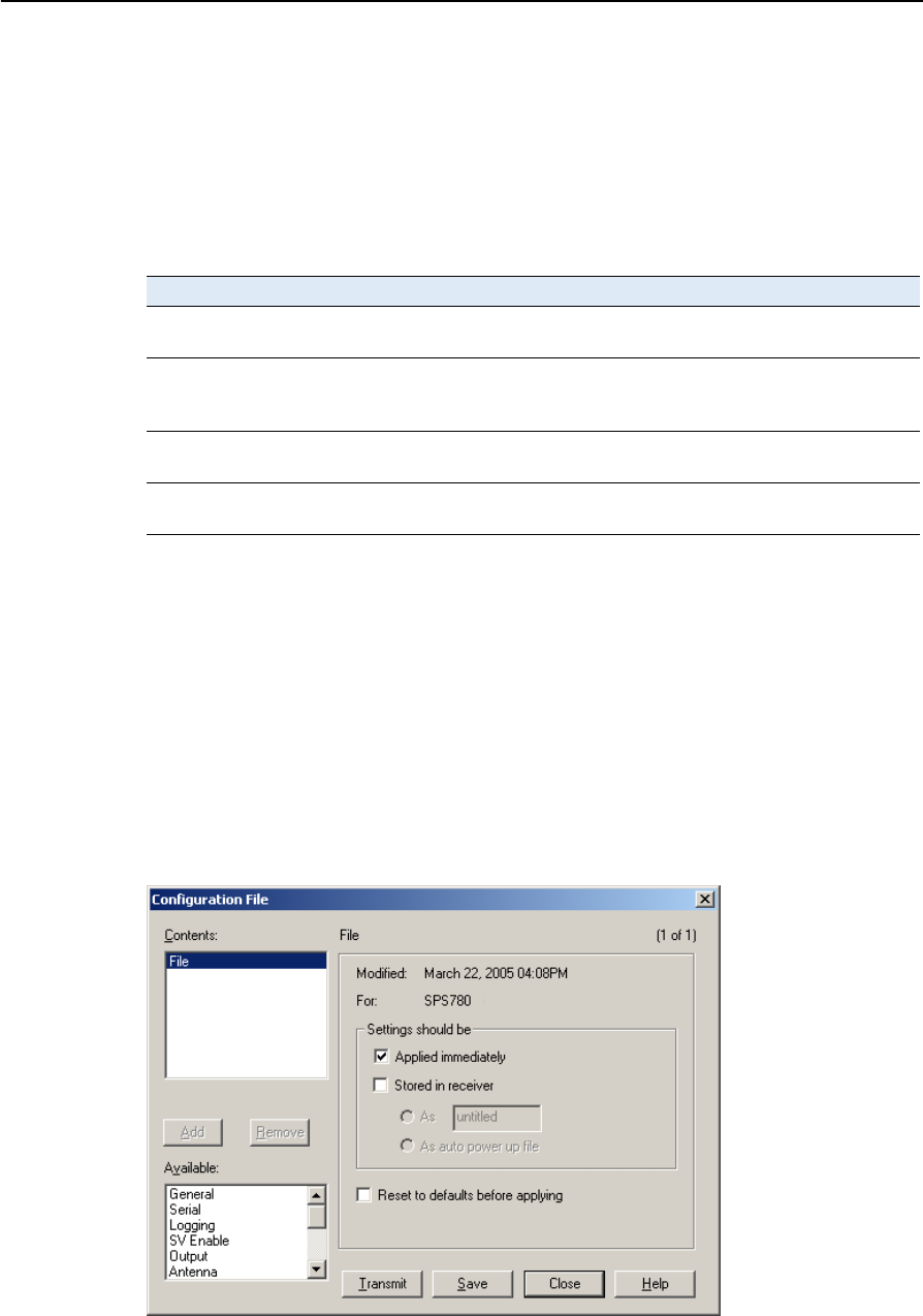
SPSx80 Smart GPS Antenna User Guide 57
Configuring the Receiver Settings 6
Installing new versions of the Configuration Toolbox software into a directory
containing a previous version overwrites the older program and data files. By default,
application files located in the root installation folder, C:\TOOLBOX, are moved to the
APPFILE\ subfolder.
The installation program creates the subfolders shown in Table 6.1 within the
installation folder.
Configuring the receiver using the Configuration Toolbox software
1. Select Start /Programs /Trimble /Configuration Toolbox.
2. Select File /New /SPSx80 or SPS770.
3. Make the appropriate selections for your receiver settings. For more
information, see the Help and the Configuration Toolbox User Guide.
4. To save the application file, select File / Save As.
Make sure that you specify the same 8-character file name when you save the file both
in the computer and on the receiver, as shown in the Configuration File dialog:
Table 6.1 Subfolders within the installation folder
Subfolder Description
bin\ Contains the Configuration Toolbox executable file (ctoolbox.exe) and
dynamic link libraries (*.dll).
appfiles\ This is the preferred directory for storing application files. Existing application
files from earlier versions of Configuration Toolbox are moved here during the
installation.
cseditor\ Contains the Coordinate System Editor executable file (cseditor.exe), dynamic
link libraries (*.dll), and help files.
geolib\ Contains the geodetic database files used by the Configuration Toolbox
software and the Coordinate System Editor software.

6 Configuring the Receiver Settings
58 SPSx80 Smart GPS Antenna User Guide
Transmitting the application file to the receiver
1. Connect the data/power cable (part number 32345) to the receiver and the
computer.
2. Connect the O-shell Lemo connector to the receiver port.
3. Connect the female DB9 connector to the computer.
4. Connect the power leads of the data/power cable to the power supply.
5. To open the application file you require, select File / Open.
6. With the file open and the Configuration File dialog open, select
Communications / Transmit File.
A message appears when the application file is successfully transmitted. If an error
occurs, select Communications / Transmit File again. This overrides any incompatibility
in baud rates and enables successful communication.
To check the successful transmission, close the Configuration File dialog and then
select Communications / Get File. A list of all application files in the receiver appears.
If you clicked Apply Immediately in the application file, the new file will be the
current file.
To change files, select the required file from the list and then select
Communications / Activate File.

CHAPTER
7
SPSx80 Smart GPS Antenna User Guide 59
AutoBase Feature 7
In this chapter:
QSetting Up a Base Station
QBest practice
QAntenna type
QScenarios
QScenario One: Base station
setup on first visit to a site
QScenario Two: Base station
setup on a repeat visit to that
site
QScenario Three: The stored
base station position seems to
be missing
QFlowchart showing the AutoBase
process
The Trimble SPS880 Extreme Smart GPS antenna
features AutoBase™ technology, which provides
the following advantages:
•Reduced risk of a setup that uses incorrect
base station coordinates.
•Reduced daily setup times for a mobile base
station. When you use an SPS880 Extreme
Smart GPS antenna as a base station
receiver, you do not need to reconfigure the
receiver at the start of each day.
The AutoBase feature is a function of the version
3.x receiver firmware, which supports both GPS
modernization (L2C and L5 signals) and
GLONASS signals. You cannot turn off the
AutoBase warning feature in the SPS880 Extreme
Smart GPS antenna.
Note – With the SPS880 Extreme Smart GPS
antenna, always start a base station setup by using
the SCS900 Site Controller software to initialize the
SPS880 Extreme Smart GPS antenna on a new
point. See page 60.
Please read this chapter even if you have used the
AutoBase feature in other Trimble receivers. New
functions now provide even greater benefits.

7 AutoBase Feature
60 SPSx80 Smart GPS Antenna User Guide
Setting Up a Base Station
The AutoBase feature influences how you set up an SPS880 Extreme Smart GPS
antenna as a base station. Before the receiver can transmit RTK corrections (that is,
operate as an RTK base station), the current position of the receiver must correspond
to a previous base station position. The base station position—latitude, longitude, and
height—must be part of the GPS site calibration.
Note – There is no need to configure the base station receiver settings manually.
1. To perform the first base station setup at a new location, always use the SCS900
Site Controller software to initialize the SPS880 Extreme Smart GPS antenna on
a new point. You generally do this only once, the first time that you occupy the
point, but see the Caution below.
When the base station setup is complete, the receiver generates and stores an
application file that contains the parameters for that location.
CCAUTION – When you perform a future base station setup at the same location, the
receiver assumes that there has been no change to either the antenna height or the
antenna height measurement method used previously. It is therefore essential that you
keep the antenna height constant between setups.
If there is any risk that the antenna height might have changed, you must use the SCS900
Site Controller software to start (and so reset) the SPS880 Extreme Smart GPS antenna.
From the SCS900 Site Controller software, select Start Base Station.
2. To perform a future base station setup at the same location, simply press the
Power key on the receiver. The receiver turns on, determines its location, finds
the appropriate application file, initializes the settings, and starts to broadcast
RTK CMR+ corrections through the internal radio or through the external radio
(whichever radio was used the previous time).
If the receiver uses an external radio, such as an SNB900 radio, the AutoBase
feature raises the Bluetooth® wireless connection to the radio. If a Bluetooth
connection is not used, the AutoBase feature searches the receiver
communications ports for the external radio. When the receiver finds the
external radio, the receiver transmits RTK CMR+ corrections to the radio.
Best practice
After each new base station setup, and at the start of every measurement session,
Trimble recommends that you measure one known point to verify that the position
and height errors are within tolerance. The measurement takes only a few seconds, but
can eliminate the gross errors typically associated with daily base station setup.
Antenna type
The selected antenna type determines which options are available for determining the
antenna height. The AutoBase feature uses an antenna type of “R8 Model 2 /SPS880
Internal.”

SPSx80 Smart GPS Antenna User Guide 61
AutoBase Feature 7
Scenarios
These scenarios describe what you may experience when using AutoBase technology.
Note – The AutoBase Warning feature is always turned on in an SPS880 Extreme Smart
GPS antenna.
Scenario One: Base station setup on first visit to a site
•You set up the base station receiver on a point that you have not previously used
as a base station with that receiver.
1. The receiver is powered on.
2. The receiver begins tracking satellites.
3. The receiver determines the current position.
4. The receiver reviews the base positions stored in the receiver.
5. The receiver does not find any base station that corresponds to the current
position.
6. The receiver will not begin transmitting RTK corrections and the radio LED will
not flash.
No RTK corrections will be streamed until the base station is set up using the SCS900
Site Controller software.
Scenario Two: Base station setup on a repeat visit to that site
•You set up the base station receiver on a point that you have previously used as
a base station with that receiver.
1. The receiver is powered on.
2. The receiver begins tracking satellites.
3. The receiver determines the current position.
4. The receiver reviews the base station positions stored in the receiver.
5. The receiver finds a base station position that corresponds to the current
position. A base station position is found, so the AutoBase warning is not
displayed.
6. The receiver loads the previous base information.
7. The antenna type, antenna height, and measurement method used in the
previous setup of this base station are applied.

7 AutoBase Feature
62 SPSx80 Smart GPS Antenna User Guide
CCAUTION – When you perform a future setup at the same location, the receiver assumes
that there has been no change to either the antenna height or the antenna height
measurement method used previously. It is therefore essential that you keep the antenna
height constant between setups.
If there is any risk that the antenna height might have changed, you must use the SCS900
Site Controller software to start (and so reset) the SPS880 Extreme Smart GPS antenna.
From the SCS900 Site Controller software, select Start Base Station.
8. The receiver begins generating RTK CMR+ corrections.
9. The RTK corrections begin streaming on the radio or port defined in the
previous setup of this base station.
Scenario Three: The stored base station position seems to be missing
•You set up the base station receiver on a point that you have previously used as
a base station, as in Scenario Two. But for some reason, the stored base station
position is not found in the receiver. Someone has inadvertently deleted the
data, or perhaps a different receiver ( for example, the other receiver in a pair)
was used on the previous occasion.
1. The base station receiver is set up on a point that you have previously used as a
base station.
2. The receiver is powered on.
3. The receiver begins tracking satellites.
4. The receiver determines the current position.
5. The receiver reviews the base station positions stored in the receiver.
6. The receiver does not find any base station that corresponds to the current
position.
7. The receiver will not begin transmitting RTK corrections and the radio LED will
not flash.
No RTK corrections will be streamed until you do one of the following things:
•Use the SCS900 Site Controller software to set up the base station.
•Change to the receiver that was previously used as the base station at this
location.
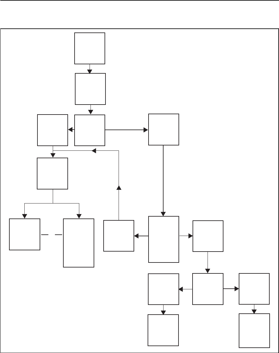
SPSx80 Smart GPS Antenna User Guide 63
AutoBase Feature 7
Flowchart showing the AutoBase process
Figure 7.1 AutoBase feature
Use SCS900
to reset and
restart the
receiver
No
AutoBase
warning is
displayed
Change to
the receiver
that was
previously
used as the
base station
at this
location
Power on
receiver
Receiver
looks for
application
files
Do
application
files exist?
No
Ye s
Any
application
file that
corresponds
with the
current
position?
No
Ye s
Ye s
Make most
recent
created
application
active
Make
corresponding
application
file active
Is there more
than one
acceptable
application
file?
or

7 AutoBase Feature
64 SPSx80 Smart GPS Antenna User Guide

CHAPTER
8
SPSx80 Smart GPS Antenna User Guide 65
Default Settings 8
In this chapter:
QDefault receiver settings
QResetting the receiver to factory
defaults
QDefault behavior
QPower up settings
QLogging data
All SPSx80 Smart GPS antenna settings are stored
in application files. The default application file,
Default.cfg, is stored permanently in the receiver,
and contains the factory default settings for the
SPSx80 Smart GPS antenna. Whenever the
receiver is reset to its factory defaults, the current
settings (stored in the current application file,
Current.cfg) are reset to the values in the default
application file.
You cannot modify the default application file.
However, you can create a power-up application
file so that the settings in this file can be applied
immediately after the default application file,
overriding the factory defaults. For more
information, see Configuring the receiver using
application files, page 53.

8 Default Settings
66 SPSx80 Smart GPS Antenna User Guide
Default receiver settings
These settings are defined in the default application file.
Resetting the receiver to factory defaults
To reset the receiver to its factory defaults, do one of the following:
•On the receiver, press E for 15 seconds.
•In the GPS Configurator software, select Connect to Receiver and then click Reset
receiver in the General tab.
•In the Configuration Toolbox software, select the General tab and then click
Reset Receiver.
Note – For more information on the GPS Configurator and Configuration Toolbox software
which are supplied on the Trimble SPS GPS Receiver CD , see Chapter 6, Configuring the
Receiver Settings.
Function Factory default
SV Enable All SVs enabled
General Controls: Elevation mask 13°
PDOP mask 7
RTK positioning mode Low Latency
Motion Kinematic
Serial Port 1: Baud rate 115,200
Format 8-None-1
Flow control None
Serial Port 2: Baud rate 115,200
Format 8-None-1
Flow control None
Input Setup: Station Any
NMEA/ASCII (all supported messages) All ports Off
Streamed output All Types Off
Offset = 00
RT17/Binary All ports Off
Reference position: Latitude 0°
Longitude 0°
Altitude 0.00 m HAE
Antenna: Type Trimble SPS780, SPS880, Internal
Height (true vertical) 0.00 m
Group All
Measurement method Bottom of mount

SPSx80 Smart GPS Antenna User Guide 67
Default Settings 8
Default behavior
The factory defaults specified on page 66 are applied whenever you start the receiver. If
a power up application file is present in the receiver, its settings are applied
immediately after the default settings, so you can use a power up file to define your
own set of defaults. The factory defaults are also applied when you perform a full reset
of the receiver because resetting the receiver deletes the power up files.
When starting any of the SPS GPS receivers as a base station or rover receiver using the
Trimble SCS900 site controller software or the HYDROpro™ software, the settings as
required for those operations are automatically set and configured in that software. To
change the receiver settings for special applications or for use with third-party
software, use the GPS Configurator software or the Configuration Toolbox software.
Power up settings
When you turn off the receiver, any changes that you have made to logging settings are
lost and these settings are returned to the factory defaults. Other settings remain as
defined in the current file. The next time you turn on the receiver, the receiver checks
for a power up file and, if one is present, applies the settings in this file.
Logging data
Logging data with the SPS GPS receivers is available as an option. By default, the data
logging option is turned off. For information on how to enable the data logging option,
and the necessary postprocessing software options, please contact your Trimble
dealer.
Data logging using GPS receivers requires you to have access to suitable GPS
postprocessing software such as Trimble Geomatics Office™ or
Trimble Total Control™. Data logging involves the collection of GPS measurement data
over a period of time at a static point or points, and subsequent postprocessing of the
information to accurately compute baseline information. Postprocessed GPS data is
typically used for control network measurement applications and precise monitoring.
The following information only applies if you have the Data Logging options enabled in
the receiver, and that you intend to carry out GPS postprocessed measurement
operations.
Logging data after a power loss
If the receiver loses power unexpectedly, when power is restored the receiver tries to
return to the state it was in immediately before the power loss. The receiver does not
reset itself to default settings. If the receiver was logging data when power was lost
unexpectedly, it resumes logging data when power is restored.

8 Default Settings
68 SPSx80 Smart GPS Antenna User Guide

CHAPTER
9
SPSx80 Smart GPS Antenna User Guide 69
Specifications 9
In this chapter:
QGeneral specifications
QPhysical specifications
QElectrical specifications
QCommunication specifications
This chapter details the specifications for the
SPSx80 Smart GPS antenna.
Specifications are subject to change without
notice.

9 Specifications
70 SPSx80 Smart GPS Antenna User Guide
General specifications
Physical specifications
Feature Specification
Keyboard and display On/Off key for one button startup using AutoBase technology
LED indicators For satellite tracking, radio link reception, and power monitoring
Receiver type Fully integrated “Smart” GPS antenna
Feature Specification
Dimensions (LxWxH) 19 cm (7.5 in) x 10 cm (3.9 in) including connectors
Weight 1.28 kg (2.88 lb) receiver only, with internal battery
3.70 kg (8.16 lbs) complete system weight, including controller and pole (when
used as a rover)
Temperature1
Operating
Storage
–40 °C to +65 °C (–40 °F to +149 °F)
–40 °C to +75 °C (–40 °F to +167 °F)
Humidity 100%, condensing
Waterproof IP67 for submersion to depth of 1 m (3.28 ft)
Shock and vibration
Shock, non operating
Shock, operating
Vibration
Tested and meets the following environmental standards:
Designed to survive a 2 m (6.6 ft) pole drop onto concrete
MIL-STD-810F, Fig.514.5C-17
To 40 G, 10 msec, saw-tooth
MIL-STD-810F, FIG.514.5C-1
Measurements • Advanced Trimble Maxwell™ Custom GPS chip
• High-precision multiple correlator for L1 and L2 pseudo-range
measurements
• Unfiltered, unsmoothed pseudo range measurements data for low noise,
low multipath error, low time domain correlation and high dynamic
response
• Very low noise L1 and L22 carrier phase measurements with <1 mm
precision in a 1 Hz bandwidth
• Proven Trimble low elevation tracking technology
• 24 Channels (SPS780 only)
• L1/L2 full cycle carrier (SPS780 only)
• L1 and L2 Signal-to-Noise ratios reported in dB-Hz
• 72 Channels L1/L2/L2C/L5 GPS and L1/L2 GLONASS (SPS880 Extreme only)
• WAAS / EGNOS support
Code differential GPS
positioning3
Horizontal accuracy
Vertical accuracy
±(0.25 m + 1 ppm) RMS, ± (9.84 in + 1 ppm) RMS
±(0.50 m + 1 ppm) RMS, ± (19.68 in + 1 ppm) RMS

SPSx80 Smart GPS Antenna User Guide 71
Specifications 9
Electrical specifications
WAAS differential
positioning accuracy4Typically <5 m (16.40 ft) 3D RMS
Real Time Kinematic (RTK)
positioning3
Horizontal
Vertical
Initialization time
Regular RTK operation
with base station
RTK operation with
Scalable GPS
infrastructure
Initialization reliability5
±(10 mm + 1 ppm) RMS, ± (0.38 in +1 ppm) RMS
±(20 mm + 1 ppm) RMS, ± (0.78 in +1 ppm) RMS
Single/Multi-base minimum 10 sec + 0.5 times baseline length in km, <30 km
<30 seconds typical anywhere within coverage area (SPS780 Max and SPS880
Extreme only).
Typically >99.9%
1 Receiver will operate normally to –40 °C. Bluetooth module and internal batteries are rated to –20 °C.
2 The availability of the L2C code GPS signal is dependent on the US government.
3 Accuracy and reliability may be subject to anomalies such as multipath, obstructions, satellite geometry, and
atmospheric conditions. Always follow recommended practices.
4 Depends on WAAS/EGNOS system performance.
5 May be affected by atmospheric conditions, signal multipath, and satellite geometry. Initialization reliability is
continuously monitored to ensure highest quality
Feature Specification
Power, internal 11 to 28 V DC external power input with over-voltage protection on
Port 1 (7-pin Lemo)
Battery Rechargeable, removable 7.4 V, 2.4 Ah Lithium-ion battery in internal
battery compartment
Power consumption <2.5 W, in RTK rover mode with internal radio
Rover operation time on
internal battery
450 MHz
900 MHz
5.5 hours; varies with temperature (Rx only)
5.5 hours; varies with temperature (Rx only)
Base station operation times on
internal battery
450 MHz
900 MHz
4.2 hours; varies with temperature (Tx/Rx)
5.5 hours; varies with temperature (External Tx radio)
Certification Class B Part 15, 22, 24FCC certification
Canada FCC
CE mark approval
C-tick approval
WEEE
Feature Specification

9 Specifications
72 SPSx80 Smart GPS Antenna User Guide
Communication specifications
Feature Specification
Communications
Port 1 (7-pin 0S Lemo)
Port 2 (DSub 9-pin)
Bluetooth
3-wire RS-232
Full RS-232
Fully integrated, fully sealed 2.4 GHz Bluetooth1
1 Bluetooth type approvals are country specific. Contact your local Trimble office or representative for more
information.
Integrated radios Fully integrated, fully sealed internal 450 MHz, TX, RX, or
Tx/Rx2
Fully integrated, fully sealed internal 900 MHz, Rx3
2 Tx only or Rx only with SPS780 Basic; Tx/Rx with SPS780 Max.
3900 MHz is Rx only with SPS780, external transmit radio must be used when configured as a base.
450 MHz transmitter radio power output 0.5 W
External GSM/GPRS, cellular phone support Supported for direct dial and Internet-based VRS correction
streams
Cellular phone or GSM/GPRS modem inside TSC2 controller
Receiver position update rate
SPS780 Basic
SPS780 Max
SPS880 Extreme
1 Hz and 2 Hz positioning
1 Hz, 2 Hz, 5 Hz, and 10 Hz positioning
1 Hz, 2 Hz, 5 Hz, 10 Hz, and 20 Hz positioning
Data Input and Output CMR, CMR+, RTCM 2.1, RTCM 2.2, RTCM 2.3, RTCM 3.0
Outputs NMEA, GSOF, and RT17
Carrier Supports BINEX and smoothed carrier (SPS880 Extreme only)

APPENDIX
A
SPSx80 Smart GPS Antenna User Guide 73
NMEA-0183 Output A
In this appendix:
QNMEA-0183 message overview
QCommon message elements
QNMEA messages
This appendix describes the formats of the
subset of NMEA-0183 messages that are available
for output by the receivers. For a copy of the
NMEA-0183 Standard, go to the National Marine
Electronics Association website at
www.nmea.org.

A NMEA-0183 Output
74 SPSx80 Smart GPS Antenna User Guide
NMEA-0183 message overview
When NMEA-0183 output is enabled, a subset of NMEA-0183 messages can be output
to external instruments and equipment connected to the receiver serial ports. These
NMEA-0183 messages let external devices use selected data collected or computed by
the GPS receiver.
All messages conform to the NMEA-0183 version 3.01 format. All begin with $ and end
with a carriage return and a line feed. Data fields follow comma (,) delimiters and are
variable in length. Null fields still follow comma (,) delimiters but contain no
information.
An asterisk (*) delimiter and checksum value follow the last field of data contained in
an NMEA-0183 message. The checksum is the 8-bit exclusive of all characters in the
message, including the commas between fields, but not including the $ and asterisk
delimiters. The hexadecimal result is converted to two ASCII characters (0–9, A–F).
The most significant character appears first.
The following table summarizes the set of NMEA messages supported by the receiver,
and shows the page that contains detailed information about each message.
To enable or disable the output of individual NMEA messages, do one of the following:
•Create an application file in the GPS Configurator software that contains NMEA
output settings and then send the file to the receiver.
•Add NMEA outputs in the Serial outputs tab of the GPS Configurator software
and then apply the settings. (You cannot use the GPS Configuration software to
load application files to the SPSx50 Modular GPS receivers.)
•For SPSx50 Modular GPS receivers, set up the NMEA output using the keypad
and display or a web browser.
Message Function Page
ADV Position and Satellite information for RTK network operations 76
GGA Time, position, and fix related data 77
GSA GPS DOP and active satellites 78
GST Position error statistics 79
GSV Number of SVs in view, PRN, elevation, azimuth, and SNR 80
HDT Heading from True North 81
PTNL,AVR Time, yaw, tilt, range, mode, PDOP, and number of SVs for
Moving Baseline RTK
82
PTNL,GGK Time, position, position type and DOP values 83
PTNL,PJK Local coordinate position output 84
PTNL,VGK Time, locator vector, type and DOP values 85
PTNL,VHD Heading Information 86
RMC Position, Velocity, and Time 87
ROT Rate of turn 88
VTG Actual track made good and speed over ground 89
ZDA UTC day, month, and year, and local time zone offset 90

SPSx80 Smart GPS Antenna User Guide 75
NMEA-0183 Output A
Common message elements
Each message contains:
•a message ID consisting of $GP followed by the message type. For example, the
message ID of the GGA message is $GPGGA.
•a comma
•a number of fields, depending on the message type, separated by commas
•an asterisk
•a checksum value
Below is an example of a simple message with a message ID ($GPGGA), followed by 13
fields and a checksum value:
$GPGGA,172814.0,3723.46587704,N,12202.26957864,W,2,6,1.2,18.893,M,-
25.669,M,2.0,0031*4F
Message values
NMEA messages that the receiver generates contains the following values.
Latitude and longitude
Latitude is represented as ddmm.mmmm and longitude is represented as
dddmm.mmmm, where:
•dd or ddd is degrees
•mm.mmmm is minutes and decimal fractions of minutes
Direction
Direction (north, south, east, or west) is represented by a single character: N, S, E, or W.
Time
Time values are presented in Universal Time Coordinated (UTC) and are represented
as hhmmss.cc, where:
•hh is hours, from 00 through 23
•mm is minutes
•ss is seconds
•cc is hundredths of seconds
NMEA messages
When NMEA-0183 output is enabled, the following messages can be generated.

A NMEA-0183 Output
76 SPSx80 Smart GPS Antenna User Guide
ADV Position and Satellite information for RTK network operations
An example of the ADV message string is shown below. Table A.1 and Table A.2
describe the message fields. The messages alternate between subtype 110 and 120.
$PGPPADV,110,39.88113582,-105.07838455,1614.125*1M
$PGPPADV,120,21,76.82,68.51,29,20.66,317.47,28,52.38,276.81,22,42.26,198.96*5D
Table A.1 ADV subtype 110 message fields
Field Meaning
0 message ID $PPGPADV
1 Message sub-type 110
2Latitude
3 Longitude
4 Ellipsoid height
6 Elevation of second satellite, in degrees, 90° maximum
7 Azimuth of second satellite, degrees from True North, 000° through 359°
8 The checksum data, always begins with *
Table A.2 ADV subtype 120 message fields
Field Meaning
0 message ID $PPGPADV
1 Message sub-type 120
2 First SV PRN number
3 Elevation of first satellite, in degrees, 90° maximum
4 Azimuth of first satellite, degrees from True North, 000° through 359°
5 Second SV PRN number
6 Elevation of second satellite, in degrees, 90° maximum
7 Azimuth of second satellite, degrees from True North, 000° through 359°
8 The checksum data, always begins with *

SPSx80 Smart GPS Antenna User Guide 77
NMEA-0183 Output A
GGA Time, Position, and Fix Related Data
An example of the GGA message string is shown below. Table A.3 describes the
message fields.
$GPGGA,172814.0,3723.46587704,N,12202.26957864,W,
2,6,1.2,18.893,M,-25.669,M,2.0,0031*4F
Table A.3 GGA message fields
Field Meaning
0 message ID $GPGGA
1 UTC of position fix
2Latitude
3 Direction of latitude:
N: North
S: South
4 Longitude
5 Direction of longitude:
E: East
W: West
6 GPS Quality indicator:
0: Fix not valid
1: GPS fix
2: Differential GPS fix
4: Real Time Kinematic, fixed integers
5: Real Time Kinematic, float integers
7 Number of SVs in use, range from 00 through 12
8 HDOP
9 Orthometric height (MSL reference)
10 M: unit of measure for orthometric height is meters
11 Geoid separation
12 M: geoid separation is measured in meters
13 Age of differential GPS data record, Type 1 or Type 9. Null field when DGPS is
not used.
14 Reference station ID, ranging from 0000 through 1023. A null field when any
reference station ID is selected and no corrections are received.
15 The checksum data, always begins with *

A NMEA-0183 Output
78 SPSx80 Smart GPS Antenna User Guide
GSA GPS DOP and active satellites
An example of the GSA message string is shown below. Table A.4 describes the
message fields.
$GPGSA,<1>,<2>,<3>,<3>,,,,,<3>,<3>,<3>,<4>,<5>,<6>*<7><CR><LF>
Table A.4 GSA message fields
Field Meaning
0 message ID $GPGSA
1Mode 1, M = manual, A = automatic
2 Mode 2, Fix type, 1 = not available, 2 = 2D, 3 = 3D
3 PRN number, 01 through 32, of satellite used in solution, up to 12 transmitted
4 PDOP-Position dilution of precision, 0.5 through 99.9
5 HDOP-Horizontal dilution of precision, 0.5 through 99.9
6 VDOP-Vertical dilution of precision, 0.5 through 99.9
7 The checksum data, always begins with *

SPSx80 Smart GPS Antenna User Guide 79
NMEA-0183 Output A
GST Position Error Statistics
An example of the GST message string is shown below. Table A.5 describes the
message fields.
$GPGST,172814.0,0.006,0.023,0.020,273.6,0.023,0.020,0.031*6A
Table A.5 GST message fields
Field Meaning
0 message ID $GPGST
1 UTC of position fix
2 RMS value of the pseudorange residuals; includes carrier phase residuals during
periods of RTK(float) and RTK(fixed) processing
3 Error ellipse semi-major axis 1 sigma error, in meters
4 Error ellipse semi-minor axis 1 sigma error, in meters
5 Error ellipse orientation, degrees from true north
6 Latitude 1 sigma error, in meters
7 Longitude 1 sigma error, in meters
8 Height 1 sigma error, in meters
9 The checksum data, always begins with *

A NMEA-0183 Output
80 SPSx80 Smart GPS Antenna User Guide
GSV Satellite Information
The GSV message string identifies the number of SVs in view, the PRN numbers,
elevations, azimuths, and SNR values. An example of the GSV message string is shown
below. Table A.6 describes the message fields.
$GPGSV,4,1,13,02,02,213,,03,-3,000,,11,00,121,,14,13,172,05*67
Table A.6 GSV message fields
Field Meaning
0 message ID $GPGSV
1 Total number of messages of this type in this cycle
2 Message number
3 Total number of SVs visible
4 SV PRN number
5 Elevation, in degrees, 90° maximum
6 Azimuth, degrees from True North, 000° through 359°
7 SNR, 00–99 dB (null when not tracking)
8–11 Information about second SV, same format as fields 4 through 7
12–15 Information about third SV, same format as fields 4 through 7
16–19 Information about fourth SV, same format as fields 4 through 7
20 The checksum data, always begins with *

SPSx80 Smart GPS Antenna User Guide 81
NMEA-0183 Output A
HDT Heading from True North
The HDT string is shown below, and Table A.7 describes the message fields.
$GPHDT,123.456,T*00
Table A.7 Heading from true north fields
Field Meaning
0 message ID $GPHDT
1 Heading in degrees
2 T: Indicates heading relative to True North
3 The checksum data, always begins with *

A NMEA-0183 Output
82 SPSx80 Smart GPS Antenna User Guide
PTNL,AVR
Time, Yaw, Tilt, Range for Moving Baseline RTK
The PTNL,AVR message string is shown below, and Table A.8 describes the message
fields.
$PTNL,AVR,181059.6,+149.4688,Yaw,+0.0134,Tilt,,,60.191,3,2.5,6*00
Table A.8 AVR message fields
Field Meaning
0 message ID $PTNL,AVR
1UTC of vector fix
2 Yaw angle in degrees
3Yaw
4 Tilt angle in degrees
5Tilt
6 Reserved
7 Reserved
8 Range in meters
9 GPS quality indicator:
0: Fix not available or invalid
1: Autonomous GPS fix
2: Differential carrier phase solution RTK (Float)
3: Differential carrier phase solution RTK (Fix)
4: Differential code-based solution, DGPS
10 PDOP
11 Number of satellites used in solution
12 The checksum data, always begins with *

SPSx80 Smart GPS Antenna User Guide 83
NMEA-0183 Output A
PTNL,GGK
Time, Position, Position Type, DOP
An example of the PTNL,GGK message string is shown below. Table A.9 describes the
message fields.
$PTNL,GGK,172814.00,071296,3723.46587704,N,12202.26957864,W,3,06,1.7,EHT-
6.777,M*48
Note – The PTNL,GGK message is longer than the NMEA-0183 standard of 80 characters.
Table A.9 PTNL,GGK message fields
Field Meaning
0 message ID $PTNL,GGA
1 UTC of position fix
2Date
3Latitude
4 Direction of latitude:
N: North
S: South
5 Longitude
6 Direction of Longitude:
E: East
W: West
7 GPS Quality indicator:
0: Fix not available or invalid
1: Autonomous GPS fix
2: Differential, floating carrier phase integer-based solution, RTK(float)
3: Differential, fixed carrier phase integer-based solution, RTK(fixed)
4: Differential, code phase only solution (DGPS). Also, OmniSTAR XP/HP
converging
5: SBAS solution – WAAS, EGNOS
6: RTK Float 3D in a VRS/Network. Also OmniSTAR XP/HP converged
7: RTK Fixed 3D in a VRS/Network
8: RTK Float 2D in a VRS/Network
8 Number of satellites in fix
9DOP of fix
10 Ellipsoidal height of fix
11 M: ellipsoidal height is measured in meters
12 The checksum data, always begins with *

A NMEA-0183 Output
84 SPSx80 Smart GPS Antenna User Guide
PTNL,PJK
Local Coordinate Position Output
An example of the PTNL,PJK message string is shown below. Table A.10 describes the
message fields.
$PTNL,PJK,010717.00,081796,+732646.511,N,+1731051.091,E,1,05,2.7,EHT-
28.345,M*7C
Note – The PTNL,PJK message is longer than the NMEA-0183 standard of 80 characters.
Table A.10 PTNL,PJK message fields
Field Meaning
0 message ID $PTNL,PJK
1 UTC of position fix
2Date
3 Northing, in meters
4 Direction of Northing will always be N (North)
5 Easting, in meters
6 Direction of Easting will always be E (East)
7 GPS Quality indicator:
0: Fix not available or invalid
1: Autonomous GPS fix
2: Differential, floating carrier phase integer-based solution, RTK(float)
3: Differential, fixed carrier phase integer-based solution, RTK(fixed)
4: Differential, code phase only solution (DGPS). Also, OmniSTAR XP/HP
converging
5: SBAS solution – WAAS, EGNOS
6: RTK Float 3D in a VRS/Network. Also OmniSTAR XP/HP converged
7: RTK Fixed 3D in a VRS/Network
8: RTK Float 2D in a VRS/Network
8 Number of satellites in fix
9DOP of fix
10 Ellipsoidal height of fix
11 M: ellipsoidal height is measured in meters
12 The checksum data, always begins with *

SPSx80 Smart GPS Antenna User Guide 85
NMEA-0183 Output A
PTNL,VGK
Vector Information
An example of the PTNL,VGK message string is shown below. Table A.11 describes the
message fields.
$PTNL,VGK,160159.00,010997,-0000.161,00009.985,-0000.002,3,07,1,4,M*0B
Table A.11 PTNL,VGK message fields
Field Meaning
0 message ID $PTNL,VGK
1 UTC of vector in hhmmss.ss format
2 Date in mmddyy format
3 East component of vector, in meters
4 North component of vector, in meters
5 Up component of vector, in meters
6 GPS Quality indicator:
0: Fix not available or invalid
1: Autonomous GPS fix
2: Differential, floating carrier phase integer-based solution, RTK(float)
3: Differential, fixed carrier phase integer-based solution, RTK(fixed)
4: Differential, code phase only solution (DGPS). Also, OmniSTAR XP/HP
converging
5: SBAS solution – WAAS, EGNOS
6: RTK Float 3D in a VRS/Network. Also OmniSTAR XP/HP converged
7: RTK Fixed 3D in a VRS/Network
8: RTK Float 2D in a VRS/Network
7 Number of satellites if fix solution
8DOP of fix
9 M: Vector components are in meters
10 The checksum data, always begins with *

A NMEA-0183 Output
86 SPSx80 Smart GPS Antenna User Guide
PTNL,VHD
Heading Information
An example of the PTNL,VHD message string is shown below. Table A.12 describes the
message fields.
$PTNL,VHD,030556.00,093098,187.718,-22.138,-76.929,-
5.015,0.033,0.006,3,07,2.4,M*22
Table A.12 PTNL,VHD message fields
Field Meaning
0 message ID $PTNL,VHD
1 UTC of position in hhmmss.ss format
2 Date in mmddyy format
3Azimuth
4ΔAzimuth/ΔTime
5 Vertical Angle
6ΔVertical/ΔTime
7Range
8ΔRange/ΔTime
9 GPS Quality indicator:
0: Fix not available or invalid
1: Autonomous GPS fix
2: Differential, floating carrier phase integer-based solution, RTK(float)
3: Differential, fixed carrier phase integer-based solution, RTK(fixed)
4: Differential, code phase only solution (DGPS). Also, OmniSTAR XP/HP
converging
5: SBAS solution – WAAS, EGNOS
6: RTK Float 3D in a VRS/Network. Also OmniSTAR XP/HP converged
7: RTK Fixed 3D in a VRS/Network
8: RTK Float 2D in a VRS/Network
10 Number of satellites used in solution
11 PDOP
12 The checksum data, always begins with *

SPSx80 Smart GPS Antenna User Guide 87
NMEA-0183 Output A
RMC Position, Velocity, and Time
The RMC string is shown below, and Table A.13 describes the message fields.
$GPRMC,123519,A,4807.038,N,01131.000,E,022.4,084.4,230394,003.1,W*6A
Table A.13 GPRMC message fields
Field Meaning
0 message ID $GPRMC
1 UTC of position fix
2 Status A=active or V=void
3Latitude
4 Longitude
5 Speed over the ground in knots
6 Track angle in degrees (True)
7Date
8 Magnetic variation in degrees
9 The checksum data, always begins with *

A NMEA-0183 Output
88 SPSx80 Smart GPS Antenna User Guide
ROT Rate and Direction of Turn
The ROT string is shown below, and Table A.14 describes the message fields.
$GPROT,35.6,A*4E
Table A.14 ROT message fields
Field Meaning
0 message ID $GPROT
1 Rate of turn, degrees/minutes, "–" indicates bow turns to port
2 A: Valid data
V: Invalid data
3 The checksum data, always begins with *

SPSx80 Smart GPS Antenna User Guide 89
NMEA-0183 Output A
VTG Track Made Good and Speed Over Ground
An example of the VTG message string is shown below. Table A.15 describes the
message fields.
$GPVTG,,T,,M,0.00,N,0.00,K*4E
Table A.15 VTG message fields
Field Meaning
0 message ID $GPVTG
1 Track made good (degrees true)
2 T: track made good is relative to true north
3 Track made good (degrees magnetic)
4 M: track made good is relative to magnetic north
5 Speed, in knots
6 N: speed is measured in knots
7 Speed over ground in kilometers/hour (kph)
8 K: speed over ground is measured in kph
9 The checksum data, always begins with *

A NMEA-0183 Output
90 SPSx80 Smart GPS Antenna User Guide
ZDA UTC Day, Month, And Year, and Local Time Zone Offset
An example of the ZDA message string is shown below. Table A.16 describes the
message fields.
$GPZDA,172809,12,07,1996,00,00*45
Fields 5 and 6 together yield the total offset. For example, if field 5 is –5 and field 6 is
+15, local time is 5 hours and 15 minutes earlier than GMT.
Table A.16 ZDA message fields
Field Meaning
0 message ID $GPZDA
1UTC
2 Day, ranging between 01 and 31
3 Month, ranging between 01 and 12
4Year
5 Local time zone offset from GMT, ranging from 00 through ±13 hours
6 Local time zone offset from GMT, ranging from 00 through 59 minutes
7The checksum data, always begins with *

APPENDIX
B
SPSx80 Smart GPS Antenna User Guide 91
GSOF Messages B
In this appendix:
QSupported message types
QGSOF message definitions
This appendix provides information on the
General Serial Output Format (GSOF) messages
that the SPS GPS receivers support. GSOF
messages are a Trimble proprietary format and
can be used to send information such as position
and status to a third-party device.
For information on how to output GSOF
messages from the SPSx50 Modular GPS receiver,
refer to Chapter 6, Configuring the SPSx50 Using
the Keypad and Display and Chapter 7,
Configuring the Receiver Settings in the SPSx50
Modular GPS Receiver User Guide.

B GSOF Messages
92 SPSx80 Smart GPS Antenna User Guide
Supported message types
This table summarizes the GSOF messages that are supported by the receiver, and
shows the page that contains detailed information about each message.
GSOF message definitions
When GSOF output is enabled, the following messages can be generated.
TIME
This message describes position time information. It contains the following data:
•GPS time, in milliseconds of GPS week
•GPS week number
•Number of satellites used
•Initialization counter
Message Description Page
TIME Position time 92
LLH Latitude, longitude, height 93
ECEF Earth-Centered, Earth-Fixed position 93
ECEF DELTA Earth-Centered, Earth-Fixed Delta position 94
NEU DELTA Tangent Plane Delta 94
Velocity Velocity data 95
PDOP PDOP info 95
SIGMA Position Sigma info 95
SV Brief SV Brief info 96
SV Detail SV Detailed info 97
UTC Current UTC time 98
BATT/MEM Receiver battery and memory status 98
ATTITUDE Attitude info 99
Table B.1 Time (Type 1 record)
Field Item Type Value Meaning
0 Output record type Char 01h Position time output record
1 Record length Char 0Ah Bytes in record
2–5 GPS time (ms) Long msecs GPS time, in milliseconds of GPS week
6–7 GPS week number Short number GPS week count since January 1980
8 Number of SVs used Char 00h-0Ch Number of satellites used to determine the
position (0-12)
9 Position flags 1 Char See Table B.14 Reports first set of position attribute flag
values

SPSx80 Smart GPS Antenna User Guide 93
GSOF Messages B
LLH
This message describes latitude, longitude, and height. It contains the following data:
•WGS-84 latitude and longitude, in radians
•WGS-84 height, in meters
ECEF
This message describes the ECEF position. It contains the following data:
•Earth-Centered, Earth-Fixed X, Y, Z coordinates, in meters
10 Position flags 2 Char See Table B.15 Reports second set of position attribute flag
values
11 Initialized number Char 00h-FFh Increments with each initialization (modulo
256)
Table B.2 Latitude, longitude, height (Type 2 record)
Field Item Type Value Meaning
0 Output record type Char 02h Latitude, longitude, and height output record
1 Record length Char 18h Bytes in record
2–9 Latitude Double Radians Latitude from WGS-84 datum
10–17 Longitude Double Radians Longitude from WGS-84 datum
18–25 Height Double Meters Height from WGS-84 datum
Table B.3 ECEF position (Type 3 record)
Field Item Type Value Meaning
0 Output record type Char 03h Earth-Centered, Earth-Fixed (ECEF) position output
record
1 Record length Char 18h Bytes in record
2–9 X Double Meters WGS-84 ECEF X-axis coordinate
10–17 Y Double Meters WGS-84 ECEF Y-axis coordinate
18–25 Z Double Meters WGS-84 ECEF Z-axis coordinate
Table B.1 Time (Type 1 record)
Field Item Type Value Meaning

B GSOF Messages
94 SPSx80 Smart GPS Antenna User Guide
ECEF DELTA
This message describes the ECEF Delta position. It contains the following data:
•Earth-Centered, Earth-Fixed X, Y, Z deltas between the rover and base position,
in meters.
NEU DELTA
This message contains Tangent Plane Delta information. It contains the following
data:
•North, East, and Up deltas of the vector from the base to the rover (in meters)
projected onto a plane tangent to the WGS-84 ellipsoid at the base receiver.
Note – These records are only output if a valid DGPS/RTK solution is computed.
Table B.4 ECEF Delta (Type 6 record)
Field Item Type Value Meaning
0 Output record type Char 06h Earth-Centered, Earth-Fixed (ECEF) Delta output record
1 Record length Char 18h Bytes in record
2–9 Delta X Double Meters ECEF X-axis delta between rover and base station
positions
10–17 Delta Y Double Meters ECEF Y-axis delta between rover and base station
positions
18–25 Delta Z Double Meters ECEF Z-axis delta between rover and base station
positions
Table B.5 NEU Delta (Type 7 record)
Field Item Type Value Meaning
0 Output record type Char 07h Tangent Plane Delta output record
1 Record length Char 18h Bytes in record
2–9 Delta east Double meters East component of vector from base station to rover,
projected onto a plane tangent to the WGS-84 ellipsoid
at the base station
10–17 Delta north Double meters North component of tangent plane vector
18–25 Delta up Double meters Difference between ellipsoidal height of tangent plane
at base station and a parallel plane passing through
rover point

SPSx80 Smart GPS Antenna User Guide 95
GSOF Messages B
Velocity
This message provides velocity information. It contains the following data:
•Horizontal velocity, in meters per second
•Vertical velocity, in meters per second
•Heading, in radians, referenced to WGS-84 True North
PDOP
This message describes the PDOP information. It contains the following data:
•PDOP
•HDOP
•VDOP
•TDOP
SIGMA
This message describes the Position Sigma information. It contains the following data:
•Position RMS
•Sigma east, in meters
•Sigma north, in meters
•Sigma up, in meters
Table B.6 Velocity (Type 8 record)
Field Item Type Value Meaning
0 Output record type Char 08h Velocity data output record
1 Record length Char 0Dh Bytes in record
2 Velocity flags Char See Table B.17 Velocity status flags
3–6 Speed Float Meters per second Horizontal speed
7–10 Heading Float Radians True north heading in the WGS-84 datum
11–14 Vertical velocity Float Meters per second Vertical velocity
Table B.7 PDOP (Type 9 record)
Field Item Type Value Meaning
0 Output record type Char 09h PDOP information output record
1 Record length Char 10h Bytes in record
2–5 PDOP Float Positional Dilution of Precision
6–9 HDOP Float Horizontal Dilution of Precision
10–13 VDOP Float Vertical Dilution of Precision
14–17 TDOP Float Time Dilution of Precision

B GSOF Messages
96 SPSx80 Smart GPS Antenna User Guide
•Covariance east-north
•Error Ellipse Semi-major axis, in meters
•Error Ellipse Semi-minor axis, in meters
•Orientation of Semi-major axis in degrees from True North
•Unit variance
•Number of epochs
SV Brief
This message provides brief satellite information. It contains the following data:
•Number of satellites tracked
•The PRN number of each satellite
•Flags indicating satellite status
Table B.8 Sigma (Type 12 record)
Field Item Type Value Meaning
0 Output record type Char 0Ch Position sigma information output record
1 Record length Char 26h Bytes in record
2–5 Position RMS Float Root means square of position error calculated
for overdetermined positions
6–9 Sigma east Float Meters
10–13 Sigma north Float Meters
14–17 Covar. east-north Float number Covariance east-north (dimensionless)
18–21 Sigma up Float Meters
22–25 Semi-major axis Float Meters Semi-major axis of error ellipse
26–29 Semi-minor axis Float Meters Semi-minor axis of error ellipse
30–33 Orientation Float degrees Orientation of semi-minor axis, clockwise from
True North
34–37 Unit variance Float Valid only for over-determined solutions. Unit
variance should approach 1.0 value. A value of
less than 1.0 indicates that apriori variances are
too pessimistic.
30–39 Number of epochs short count Number of measurement epochs used to
compute the position. Could be greater than 1
for positions subjected to static constraint.
Always 1 for kinematic.
Table B.9 SV brief (Type 13 record)
Field Item Type Value Meaning
0 Output record type Char 0Dh Brief satellite information output record
1 Record length Char Bytes in record
2 Number of SVs Char 00h-18h Number of satellites included in record1

SPSx80 Smart GPS Antenna User Guide 97
GSOF Messages B
SV Detail
This message provides detailed satellite information. It contains the following data:
•Number of satellites tracked
•The PRN number of each satellite
•Flags indicating satellite status
•Elevation above horizon, in degrees
•Azimuth from True North, in degrees
•Signal-to-noise ratio (SNR) of L1 signal
•Signal-to-noise ratio (SNR) of L2 signal
The following bytes are repeated for Number of SVs
PRN Char 01h-20h Pseudorandom number of satellites (1-32)
SV Flags1 Char See Table B.18 First set of satellite status bits
SV Flags2 Char See Table B.19 Second set of satellite status bits
1Includes all tracked satellites, all satellites used in the position solution, and all satellites in view.
Table B.10 SV detail (Type 14 record)
Field Item Type Value Meaning
0 Output record
type
Char 0Eh Detailed satellite information output record
1 Record length Char 1 + 8×(number of SVs) Bytes in record
2–9 Number of SVs Char 00h-18h Number of satellites included in record1
1Includes all tracked satellites, all satellites used in the position solution, and all satellites in view.
The following bytes are repeated for Number of SVs
PRN Char 01h-20h Pseudorandom number of satellites (1–32)
Flags1 Char See Table B.18 First set of satellite status bits
Flags2 Char See Table B.19 Second set of satellite status bits
Elevation Char Degrees Angle of satellite above the horizon
Azimuth Short Degrees Azimuth of satellite from True North
SNR L1 Char dB * 4 Signal-to-noise ratio of L1 signal (multiplied
by 4)2
2THe SNR L1 and SNR L2 items are set to zero for satellites that are not tracked on the current frequency.
SNR L2 Char dB * 4 Signal-to-noise ratio of L2 signal (multiplied
by 4)2
Table B.9 SV brief (Type 13 record)
Field Item Type Value Meaning

B GSOF Messages
98 SPSx80 Smart GPS Antenna User Guide
UTC
This message describes current time information. It contains the following data:
•GPS time, in milliseconds of GPS week
•GPS week number
•GPS to UTC time offset, in seconds
Batt/Mem
This message provides information relating to the receiver battery and memory. It
contains the following data:
•Remaining battery power
•Remaining memory
Table B.11 UTC (Type 16 record)
Field Item Type Value Meaning
0 Output record type Char 10h
1 Record length Char 09h Bytes in record
2–5 GPS millisecond of
week
Long msecs Time when packet is sent from the receiver, in GPS
milliseconds of week
6–7 GPS week number Short number Week number since start of GPS time
8–9 UTC offset Short seconds GPS to UTC time offset
10 Flags Char See Table B.16 Flag bits indicating validity of Time and UTC offsets
Table B.12 Batt/Mem (Type 37 record)
Field Item Type Value Meaning
0 Output record type Char 25h
1 Record length Char 0Ah Bytes in record
2–3 Battery capacity Unsigned short percentage Remaining battery capacity in percentage
4–11 Remaining memory Double hours Estimated remaining data logging time in
hours

SPSx80 Smart GPS Antenna User Guide 99
GSOF Messages B
Attitude
This message provides attitude information relating to the vector between the Heading
antenna and the Moving Base antenna. It contains the following data:
•Tilt or vertical angle, in radians, from the Heading antenna to the Moving Base
antenna relative to a horizontal plane through the Heading antenna
•Heading or yaw, in radians, relative to True North
•Range or slope distance between the Heading antenna and the Moving Base
antenna
Table B.13 Attitude (Type 27 record)
Field Item Type Value Meaning
0 Output record type Char 1Bh Attitude information
1 Record length Char 2Ah Bytes in record
2–5 GPS time Long msecs GPS time in milliseconds of GPS week
6 Flags Char See Table B.20 Flag bits indicating validity of attitude components
7 Number of SVs used Char 00h-0Ch Number of satellites used to calculate attitude
8 Calculation mode Char See Table B.21 Positioning mode
9 Reserved Reserved
10–17 Tilt Double radians Tilt relative to horizontal plane
18–25 Yaw Double radians Rotation about the vertical axis relative to True
North
26–33 Reserved Reserved
34–41 Range Double meters Distance between antennas
42–43 PDOP Short 0.1 Position Dilution of Precision

B GSOF Messages
100 SPSx80 Smart GPS Antenna User Guide
Flags
Table B.14 Position flags 1: bit values
Bit Meaning
0 New position
0: No. 1: Yes.
1 Clock fix calculated for current position
0: No. 1: Yes.
2 Horizontal coordinates calculated this position
0: No. 1: Yes.
3 Height calculated this position
0: No. 1: Yes.
4 Weighted position
0: No. 1: Yes.
5 Overdetermined position
0: No. 1: Yes.
6 Ionosphere-free position
0: No. 1: Yes.
7 Position uses filtered L1 pseudoranges
0: No. 1: Yes.
Table B.15 Position flags 2: bit values
Bit Meaning
0 Differential position
0: No. 1: Yes.
1 Differential position method
0: RTCM (Code)
1: RTK, OmniSTAR HP (Phase)
2 Differential position method
0: Differential position is code (RTCM) or a float position (RTK)
1: Differential position is a fixed integer phase position (RTK if Bit-0 = 1, WAAS
if Bit-0=0)
3OmniSTAR HP
0: Not active
1: OmniSTAR HP differential solution
4 Position determined with static as a constant
0: No. 1: Yes.
5 Position is network RTK solution
0: No. 1: Yes.
6–7 Reserved (set to zero)

SPSx80 Smart GPS Antenna User Guide 101
GSOF Messages B
Table B.16 Flags: Bit values
Bit Meaning
0 Time information (week and millisecond of week) validity
0: Not valid
1: Valid
1 UTC offset validity
0: Not valid
1: Valid
Table B.17 Velocity flags: Bit values
Bit Meaning
0 Velocity data validity
0: Not valid
1: Valid
1 Velocity computation
0: Computed from doppler
1: Computed from consecutive measurements
2–7 Reserved (set to zero)
Table B.18 SV flags: 1 bit values
Bit Meaning
0 Satellite Above Horizon
0: No. 1: Yes.
1 Satellite Currently Assigned to a Channel (trying to track)
0: No. 1: Yes.
2 Satellite Currently Tracked on L1 Frequency
0: No. 1: Yes.
3 Satellite Currently Tracked on L2 Frequency
0: No. 1: Yes.
4 Satellite Reported at Base on L1 Frequency
0: No. 1: Yes.
5 Satellite Reported at Base on L2 Frequency
0: No. 1: Yes.
6 Satellite Used in Position
0: No. 1: Yes.
7 Satellite Used in Current RTK Process (Search, Propagate, Fix Solution)
0: No. 1: Yes.
Table B.19 SV flags: 2 bit value
Bit Meaning
0 Satellite Tracking P-Code on L1 Band
0: No. 1: Yes.
1 Satellite Tracking P-Code on L2 Band
0: No. 1: Yes.
2–7 Reserved. Set to zero.

B GSOF Messages
102 SPSx80 Smart GPS Antenna User Guide
Data collector report structure
Table B.20 Attitude flags
Bit Meaning
0Calibrated
0: No. 1: Yes.
1 Tilt valid
0: No. 1: Yes.
2 Yaw valid
0: No. 1: Yes.
3 Reserved
4 Range valid
0: No. 1: Yes.
5–7 Reserved
Table B.21 Attitude calculation flags
Bit Meaning
0 0: No position
1: Autonomous position
2: RTK/Float position
3: RTK/Fix position
4: DGPS position
Table B.22 Report packet 40h structure
Byte Item Type Value Meaning
0 STX CHAR 02h Start transmission.
1 STATUS CHAR See Table B.23 Receiver status code.
2 PACKET TYPE CHAR 40h Report Packet 40h.
3 LENGTH CHAR 00h–FAh Data byte count.
4 TRANSMISSION
NUMBER
CHAR Unique number assigned to a group of
record packet pages. Prevents page
mismatches when multiple sets of
record packets exist in output stream.
5 PAGE INDEX CHAR 00h–FFh Index of current packet page.
6 MAX PAGE INDEX CHAR 00h–FFh Maximum index of last packet in one
group of records.
Table B.23 Receiver Status code
Byte
number
Message Description
Bit 0 1 Reserved
Bit 1 1 Low battery
Bit 2–7 0–63 Reserved

APPENDIX
C
SPSx80 Smart GPS Antenna User Guide 103
Adding Internal Radio Frequencies C
In this appendix:
QAdding receive frequencies for
the 450 MHz internal radio
If you have installed the optional internal
450 MHz radio in your GPS receiver, use the
WinFlash utility to add the relevant receive
frequencies to the default list of frequencies. To
install the WinFlash utility, see Installing the
WinFlash utility, page 140.
If you have also purchased the transmit option
(SPSx50 and SPSx80 only), Trimble must specify
and configure the (FCC-approved) transmit
broadcast frequencies at the factory. You cannot
configure these yourself.
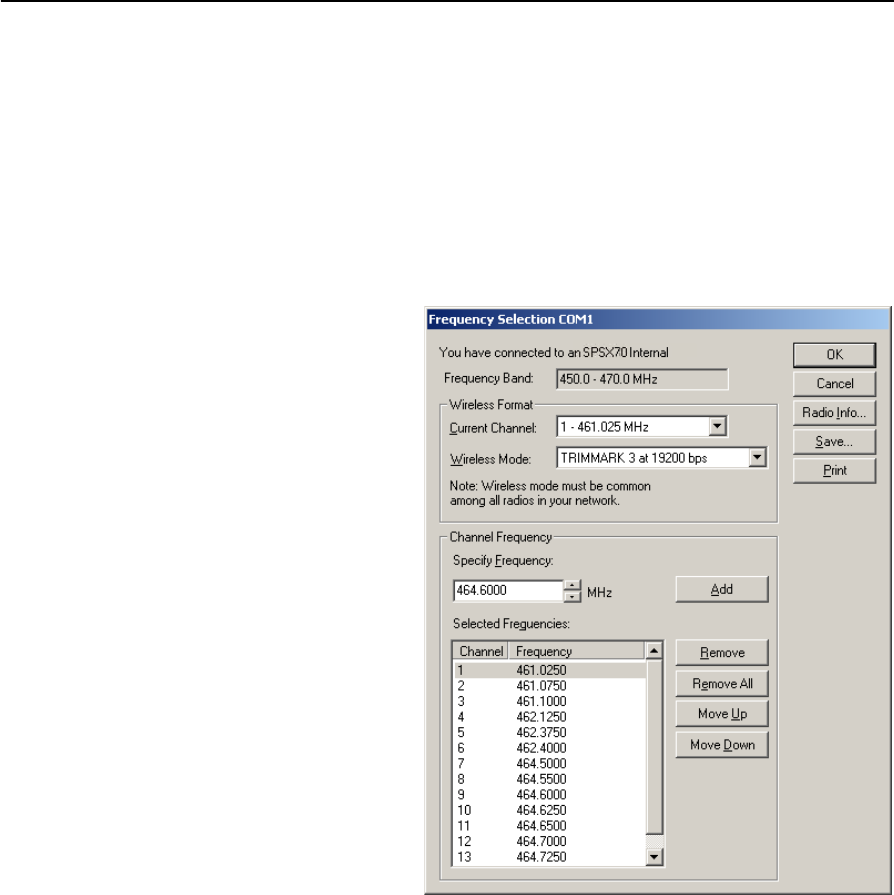
C Adding Internal Radio Frequencies
104 SPSx80 Smart GPS Antenna User Guide
Adding receive frequencies for the 450 MHz internal radio
1. Start the WinFlash utility. The Device Configuration screen appears.
2. From the Device type list, select the appropriate receiver.
3. From the PC serial port field, select the serial (COM) port on the computer that
the receiver is connected to.
4. Click Next. The Operation Selection dialog appears. The Operations list shows all
of the supported operations for the selected device. A description of the selected
operation is shown in the Description field.
5. Select Configure Radio
and then click Next. The
Frequency Selection
dialog appears:
6. In the Wireless Format
group, select the
appropriate channel and
wireless mode. The
Wireless mode must be
the same for all radios in
your network.
7. In the Specify Frequency
field, enter the frequency
you want to add.
8. Click Add. The new
frequency appears in the
Selected Frequencies list.
Note – The programmed
frequencies must conform to the
channel spacing and minimum
tuning requirements for the
radio. To view this information,
click Radio Info. You can select 12.5 kHz or 25 kHz channel spacing. All radios in your
network must use the same channel spacing.
9. Once you have configured all the frequencies that you require, click OK.
The WinFlash utility updates the receiver radio frequencies and then restarts
the receiver.

APPENDIX
D
SPSx80 Smart GPS Antenna User Guide 105
Upgrading the Receiver Firmware D
In this appendix:
QThe WinFlash utility
QUpgrading the receiver firmware
Your receiver is supplied with the latest version of
receiver firmware installed. If a later version
becomes available, upgrade the firmware
installed on your receiver using the WinFlash
utility.
You can also upgrade the SPSx50 receiver
through the web interface.

D Upgrading the Receiver Firmware
106 SPSx80 Smart GPS Antenna User Guide
The WinFlash utility
The WinFlash utility communicates with Trimble products to perform various
functions including:
•installing software, firmware, and option upgrades
•running diagnostics (for example, retrieving configuration information)
•configuring radios
For more information, online help is also available when using the WinFlash utility.
Note – The WinFlash utility runs on Microsoft Windows 95, 98, Windows NT®, 2000, Me,
or XP operating systems.
Installing the WinFlash utility
You can install the WinFlash utility from the Trimble SPS GPS Receiver CD, or from the
Trimble website.
To install the WinFlash utility from the CD:
1. Insert the disk into the CD drive on your computer.
2. From the main menu select Install individual software packages.
3. Select Install WinFlash.
4. Follow the on-screen instructions.
The WinFlash utility guides you through the firmware upgrade process, as described
below. For more information, refer to the WinFlash Help.
Upgrading the receiver firmware
1. Start the WinFlash utility. The Device Configuration screen appears.
2. From the Device type list, select your receiver.
3. From the PC serial port field, select the serial (COM) port on the computer that
the receiver is connected to.
4. Click Next.
The Operation Selection screen appears. The Operations list shows all of the
supported operations for the selected device. A description of the selected
operation is shown in the Description field.
5. Select Load GPS software and then click Next.
The GPS Software Selection window appears. This screen prompts you to select
the software that you want to install on the receiver.
6. From the Available Software list, select the latest version and then click Next.

SPSx80 Smart GPS Antenna User Guide 107
Upgrading the Receiver Firmware D
The Settings Review window appears. This screen prompts you to connect the
receiver, suggests a connection method, and then lists the receiver configuration
and selected operation.
7. If all is correct, click Finish.
Based on the selections shown above, the Software Upgrade window appears and
shows the status of the operation ( for example, Establishing communication
with <your receiver>. Please wait.).
8. Click OK.
The Software Upgrade window appears again and states that the operation was
completed successfully.
9. To select another operation, click Menu; to quit, click Exit.
If you click Exit, the system prompts you to confirm.
10. Click OK.

D Upgrading the Receiver Firmware
108 SPSx80 Smart GPS Antenna User Guide

APPENDIX
E
SPSx80 Smart GPS Antenna User Guide 109
Data Logging and Postprocessed
Measurement Operations E
In this appendix:
QConnecting to the office
computer
QTransferring files directly from a
CompactFlash card
QDeleting files in the receiver
QSupported file types
By default, the SPS GPS receivers cannot log data
unless you purchase the Data Logging option. For
more information, see Configuring the receiver to
log data for postprocessing, page 38.
The SPS770 GPS receiver keeps satellite
measurements and other data in files stored on a
CompactFlash card when the data has been used
for static measurement. An SPSx80 Smart GPS
antenna uses the internal memory of the receiver
to store this data. The data files cannot be
processed until you transfer them to your office
computer.
Note – The SPS770 GPS receiver supports a
maximum of 512 files on the CompactFlash cards.
Note – The SPS780 has an available memory of
2 MB. The SPS880 Extreme has an available
memory of 6 MB. The SPS750 Basic has an
available memory of 2 MB when the Data Logging
option is enabled. The SPS750 Max has an
available memory of 27 MB when the option is
enabled. The SPS850 Extreme has an available
memory of 27 MB when the option is enabled. None
of the receivers have a maximum file quantity limit.
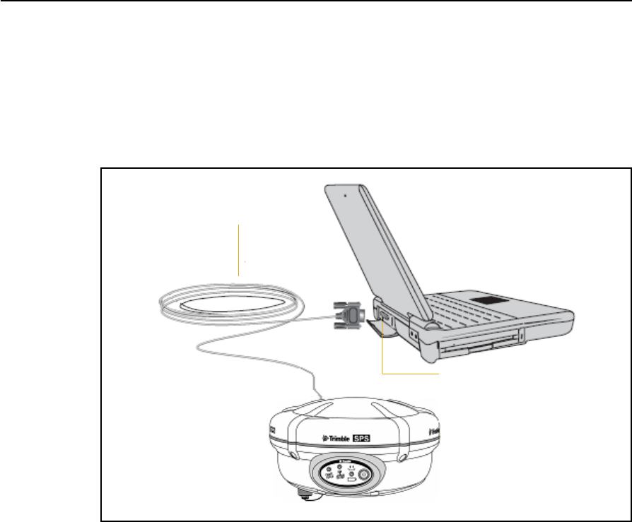
E Data Logging and Postprocessed Measurement Operations
110 SPSx80 Smart GPS Antenna User Guide
Connecting to the office computer
The SPSx80 Smart GPS antenna can communicate with the office computer using a
serial connection from the DB9 connector on the receiver to a DB9 connector on the
computer (see Figure E.1). To do this, use cable P/N 18532 that is supplied with the
receiver. Before you connect to the office computer, ensure that the receiver battery is
fully charged.
Figure E.1 Connecting the SPSx80 to a computer for serial data transfer
Transferring files directly from a CompactFlash card
In an SPS770 GPS receiver, all data is stored on an internal CompactFlash card. With a
SPSx80 Smart GPS antenna or SPSx50 Modular GPS receiver, data is stored in the
internal flash memory. There are two ways to transfer files between the receiver and
your office computer:
•Connect the receiver to the office computer and use the Data Transfer utility to
transfer files.
•With a SPS770 GPS receiver, remove the CompactFlash card from the receiver
and insert it into the CompactFlash card slot in your office computer, where it
functions like a normal disk drive. Use Windows Explorer to transfer files.
When you use the Data Transfer utility to transfer data files from the receiver, the Data
Transfer utility converts the raw receiver data (.T01) files you select into the Trimble
DAT file format.
Serial (COM) port
Serial cable

SPSx80 Smart GPS Antenna User Guide 111
Data Logging and Postprocessed Measurement Operations E
However, if you connect the CompactFlash card/USB memory device to your
computer and then copy or move files to your computer, it treats the card like any
other disk drive, and transfers the files without converting them. You need to convert
these raw receiver files to DAT format files before you can use them on your office
computer.
You can convert receiver data files by using a Windows Explorer extension which is
installed on your computer when you install the Data Transfer utility.
Deleting files in the receiver
You can delete files stored in the receiver at any time. Do one of the following:
•Press E for 30 seconds after the receiver is turned on. (When you use this
method, all data is deleted, and for a SPS770, the CompactFlash card is
reformatted.)
•Use the Data Transfer utility
•With the SPSx50 Modular GPS receiver, use the Web interface.
Supported file types
Table E.1 shows the file types that you can transfer to or from a SPS GPS receiver, and
the software or utility that you must use to transfer each file type.
Note – The SPS770 supports a maximum of 512 files on the CompactFlash card. Files
stored on the CompactFlash card must be named using the 8.3 character format. The
receiver does not support extended file names.
Table E.1 Supported file types
File Type Extensions Transfer
from
receiver
Transfer to
receiver
Software
Ephemeris .eph Yes No Data Transfer
Raw observations .T01, .dat Yes No Data Transfer
Web interface
(SPSx50)
Receiver firmware files .elf No Yes WinFlash utility
Application files
(SPS770 GPS
receiver/SPSx80 Smart GPS
antenna)
.cfg Yes Yes GPS Configurator
Configuration
Toolbox

E Data Logging and Postprocessed Measurement Operations
112 SPSx80 Smart GPS Antenna User Guide


F Troubleshooting
114 SPSx80 Smart GPS Antenna User Guide
LED conditions
The SPS770 GPS receiver and SPSx80 Smart GPS antenna have a simple display panel
with LEDs to indicate the current status of the receiver. If you need more detailed
information about what the receiver is doing, use a Trimble controller or laptop
computer running the SCS900, GPS Configurator, or Configuration Toolbox software.
The following section describes how the LED lights are used on the receiver to indicate
current status. An LED that is flashing quickly indicates a condition that may require
attention, and an unlit LED indicates that no operation is occurring. This section
describes some LED conditions, possible causes, and how to solve them.
Receiver issues
This section describes some possible receiver issues, possible causes, and how to solve
them.
Condition Possible cause Solution
The SV Tracking LED is
lit solidly and the
Logging/Memory LED is
flashing slowly.
The receiver is in Monitor
mode, ready for new
firmware to be loaded or
new options to be added.
Turn on or turn off the receiver.
Load the latest version of the
firmware, which you can download
from the Trimble website
(www.trimble.com/sps770.shtml or
www.trimble.com/sps780.shtml /
Support / Downloads).
The SV Tracking LED is
not flashing.
The receiver is tracking fewer
than four satellites. (SPS770
and SPS780 Smart GPS
antenna only)
Wait until the SV Tracking LED is
flashing slowly.
The radio antenna cable and
GPS antenna cable are mixed
up. (SPS770 only)
Make sure that the GPS antenna
cable (with the yellow over-mould) is
connected between the yellow TNC
connector marked GPS and the GPS
antenna.
Issue Possible cause Solution
The receiver does not
turn on.
External power is too low. Check the charge on the external
battery, and check the fuse if
applicable. If necessary, replace the
battery.
Internal power is too low. • Check the charge on the internal
batteries and replace if
necessary.
• Ensure battery contacts are
clean.
External power is not properly
connected.
• Check that the Lemo connection
is seated properly.
• Check for broken or bent pins in
the connector.

SPSx80 Smart GPS Antenna User Guide 115
Troubleshooting F
Faulty external power cable. • Try a different cable.
• Check pinouts with multimeter
to ensure internal wiring is
intact.
Receiver does not log
data.
Insufficient memory on either
internal memory or the
CompactFlash card.
Delete old files using the GPS
Configurator software, or press E
for 30 seconds.
No CompactFlash card is
inserted. (SPS770 only)
Insert a CompactFlash card in the
receiver.
The CompactFlash card is not
seated properly.
Remove the Compact Flash card and
reinsert it. Ensure that it slides into
the housing easily and seats into the
connector.
The CompactFlash card is not
formatted, or has been
corrupted.
Format the CompactFlash card using
the GPS Configurator software, or
press E for 30 seconds.
If the problem persists, use the GPS
Configurator software to perform a
full format.
The receiver is tracking fewer
than four satellites.
• Wait until the SV Tracking LED is
flashing slowly.
• Use the SCS900 software. Go to
the SkyPlot screen and press
[Ctrl]+[M] to access the current
elevation mask settings. Reduce
the mask value to make more
satellites available.
The default mask setting for
receiver is 13° above the horizon.
Change the value to a lower
setting temporarily while you are
waiting for a better constellation
availability.
The data logging option is
not enabled.
Check the original purchase order or
the receiver configuration using
WinFlash. If data logging is not
enabled on the receiver, you can
order the option from your local
Trimble Site Positioning Systems
dealer, and upgrade the receiver
using the WinFlash utility.
Receiver is not tracking
any satellites
GPS antenna does not have
clear line of sight to the sky.
Ensure that the antenna has a clear
line of sight.
The cable between receiver
and the GPS antenna is
damaged.
Replace the cable.
Cable connections at receiver
or antenna are not tightly
seated, or are connected
incorrectly.
Check all cable connections.
Issue Possible cause Solution

F Troubleshooting
116 SPSx80 Smart GPS Antenna User Guide
Base station setup and static measurement problems
This section describes some possible station setup and static measurement issues,
possible causes, and how to solve them.
Trimble recommends that you use the SCS900 software to restart or configure base
and rover receivers. The SCS900 software sets up all radio and receiver operating
parameters, and is the most likely route to a successful problem resolution once you
have checked all connections, cables, and batteries.
The receiver is not
responding.
Receiver needs a soft reset. Turn off the receiver and then turn it
back on again.
Receiver needs a full reset. Press E for 30 seconds.
Note – To retain data files, remove
the CompactFlash card (SPS770) or
download the files (SPS780) first.
Issue Possible cause Solution
Base station is not
broadcasting.
Port settings between base
receiver and external radio
are incorrect.
Note – The SPS770 has an
integrated RX only radio. For
use as a base station, the
receiver must be connected to
an external radio, such as a
TRIMMARK™ 3.
Note – The SPSx80 has the
option for an integrated TX
radio that allows it to be used
without an external radio at
the base and rover location.
The SPSx80 can also be
connected to an external high
power radio in certain
countries.
Using the Trimble SCS900 Site
Controller software connect to the
radio through the receiver. If no
connection is made, connect directly
to the radio and change the port
settings. Try to connect through the
receiver again to ensure that they
are communicating.
Note – The SCS900 software does
not support direct connection to the
external radio; it only allows
configuration through the receiver.
The TRIMMARK 3 and SNB900 radios
can be configured directly using the
keypad and display. The Trimble PDL
or Trimble HPB radios can be
configured using the accompanying
configuration software through a
laptop computer.
Faulty cable between receiver
and external radio
• Try a different cable
• Examine the ports for missing
pins
• Use a multimeter to check the
pins
No power to radio If the radio has its own power
supply, check the charge and
connections.
No Bluetooth connections
(SPS780 / SNB900)
Make sure that the radio and
receiver are within Bluetooth range
of each other and that the Bluetooth
antennae are visible to each other.
Issue Possible cause Solution

SPSx80 Smart GPS Antenna User Guide 117
Troubleshooting F
Roving receiver is not
receiving radio from
the base station.
The base station is not
broadcasting.
See Base station is not broadcasting.
Incorrect over air baud rates
between base station and
rover.
Connect to the roving receiver’s
radio and make sure that it has the
same setting as the base station
receiver.
Mismatched channel or
network number selection.
Match the base station and rover
radio channels/network number and
try again.
Incorrect port settings
between the rover external
radio and receiver.
If the radio is receiving data (the
Radio LED is flashing) and the
receiver is not receiving data, check
the port settings of the receiver and
radio using the Trimble SCS900 Site
Controller software; match the
settings and try again.
The radio antenna cable and
GPS antenna cable are mixed
up.
Make sure that the radio antenna
cable (with the blue over-mould) is
connected between the blue TNC
connector marked RADIO and the
radio antenna.
Issue Possible cause Solution

F Troubleshooting
118 SPSx80 Smart GPS Antenna User Guide

SPSx80 Smart GPS Antenna User Guide 119
Glossary
almanac A file that contains orbit information on all the satellites, clock corrections, and
atmospheric delay parameters. The almanac is transmitted by a GPS satellite to a GPS
receiver, where it facilitates rapid acquisition of GPS signals when you start collecting
data, or when you have lost track of satellites and are trying to regain GPS signals.
The orbit information is a subset of the emphemeris / ephemerides data.
AutoBase AutoBase technology uses the position of the receiver to automatically select the
correct base station; allowing for one button press operation of a base station. It
shortens setup time associated with repeated daily base station setups at the same
location on jobsites.
base station Also called reference station. A base station in construction, is a receiver placed at a
known point on a jobsite that tracks the same satellites as an RTK rover, and provides
a real-time differential correction message stream through radio to the rover, to obtain
centimeter level positions on a continuous real-time basis. A base station can also be a
part of a virtual reference station network, or a location at which GPS observations are
collected over a period of time, for subsequent postprocessing to obtain the most
accurate position for the location.
BINEX BInary EXchange format. BINEX is an operational binary format standard for
GPS/GLONASS/SBAS research purposes. It has been designed to grow and allow
encapsulation of all (or most) of the information currently allowed for in a range of
other formats.
broadcast server An Internet server that manages authentication and password control for a network of
VRS servers, and relays VRS corrections from the VRS server that you select.
carrier A radio wave having at least one characteristic (such as frequency, amplitude, or phase)
that can be varied from a known reference value by modulation.
carrier frequency The frequency of the unmodulated fundamental output of a radio transmitter. The GPS
L1 carrier frequency is 1575.42 MHz.
carrier phase The time taken for the L1 or L2 carrier signal generated by the satellite to reach the
GPS receiver. Measuring the number of carrier waves between the satellite and receiver
is a very accurate method of calculating the distance between them.
cellular modems A wireless adaptor that connects a laptop computer to a cellular phone system for data
transfer. Cellular modems, which contain their own antennas, plug into a PC Card slot
or into the USB port of the computer and are available for a variety of wireless data
services such as GPRS.
CMR
CMR+
Compact Measurement Record. A real-time message format developed by Trimble for
broadcasting corrections to other Trimble receivers. CMR is a more efficient
alternative to RTCM.
covanance The mean value.

Glossary
120 SPSx80 Smart GPS Antenna User Guide
datum Also called geodetic datum. A mathematical model designed to best fit the geoid,
defined by the relationship between an ellipsoid and, a point on the topographic
surface, established as the origin of the datum. World geodetic datums are typically
defined by the size and shape of an ellipsoid and the relationship between the center of
the ellipsoid and the center of the earth.
Because the earth is not a perfect ellipsoid, any single datum will provide a better
model in some locations than in others. Therefore, various datums have been
established to suit particular regions.
For example, maps in Europe are often based on the European datum of 1950 (ED-50).
Maps in the United States are often based on the North American datum of 1927
(NAD-27) or 1983 (NAD-83).
All GPS coordinates are based on the WGS-84 datum surface.
deep discharge Withdrawal of all electrical energy to the end-point voltage before the cell or battery is
recharged.
DGPS See real-time differential GPS.
differential
correction
Differential correction is the process of correcting GPS data collected on a rover with
data collected simultaneously at a base station. Because the base station is on a known
location, any errors in data collected at the base station can be measured, and the
necessary corrections applied to the rover data.
Differential correction can be done in real-time, or after the data has been collected by
postprocessing.
differential GPS See real-time differential GPS.
DOP Dilution of Precision. A measure of the quality of GPS positions, based on the geometry
of the satellites used to compute the positions. When satellites are widely spaced
relative to each other, the DOP value is lower, and position accuracy is greater. When
satellites are close together in the sky, the DOP is higher and GPS positions may
contain a greater level of error.
PDOP (Position DOP) indicates the three-dimensional geometry of the satellites. Other
DOP values include HDOP (Horizontal DOP) and VDOP (Vertical DOP), which
indicate the accuracy of horizontal measurements (latitude and longitude) and
vertical measurements respectively. PDOP is related to HDOP and VDOP as follows:
PDOP = HDOP + VDOP
dual-frequency GPS A type of receiver that uses both L1 and L2 signals from GPS satellites. A
dual-frequency receiver can compute more precise position fixes over longer distances
and under more adverse conditions because it compensates for ionospheric delays.
EGNOS European Geostationary Navigation Overlay Service. A satellite-based augmentation
system (SBAS) that provides a free-to-air differential correction service for GPS.
EGNOS is the European equivalent of WAAS, which is available in the United States.
elevation mask The angle below which the receiver will not track satellites. Normally set to 10 degrees
to avoid interference problems caused by buildings and trees, and multipath errors.
ellipsoid An ellipsoid is the three-dimensional shape that is used as the basis for mathematically
modeling the earth’s surface. The ellipsoid is defined by the lengths of the minor and
major axes. The earth’s minor axis is the polar axis and the major axis is the equatorial
axis.
emphemeris /
ephemerides
A list of predicted (accurate) positions or locations of satellites as a function of time. A
set of numerical parameters that can be used to determine a satellite’s position.
Available as broadcast ephemeris or as postprocessed precise ephemeris.

SPSx80 Smart GPS Antenna User Guide 121
Glossary
epoch The measurement interval of a GPS receiver. The epoch varies according to the
measurement type: for real-time measurement it is set at one second; for
postprocessed measurement it can be set to a rate of between one second and one
minute. For example, if data is measured every 15 seconds, loading data using
30-second epochs means loading every alternate measurement.
feature A feature is a physical object or event that has a location in the real world, which you
want to collect position and/or descriptive information (attributes) about. Features
can be classified as surface or non-surface features, and again as points,
lines/breaklines, or boundaries/areas.
firmware The program inside the receiver that controls receiver operations and hardware.
GLONASS Global Orbiting Navigation Satellite System. GLONASS is a Soviet space-based
navigation system comparable to the American GPS system. The operational system
consists of 21 operational and 3 non-operational satellites in 3 orbit planes.
GNSS Global Navigation Satellite System.
GSOF General Serial Output Format. A Trimble proprietary message format.
HDOP Horizontal Dilution of Precision. HDOP is a DOP value that indicates the accuracy of
horizontal measurements. Other DOP values include VDOP (vertical DOP) and PDOP
(Position DOP).
Using a maximum HDOP is ideal for situations where vertical precision is not
particularly important, and your position yield would be decreased by the vertical
component of the PDOP (for example, if you are collecting data under canopy).
L1 The primary L-band carrier used by GPS satellites to transmit satellite data.
L2 The secondary L-band carrier used by GPS satellites to transmit satellite data.
L5 The third L-band carrier used by GPS satellites to transmit satellite data. L5 will
provide a higher power level than the other carriers. As a result, acquiring and tracking
weak signals will be easier.
Moving Base Moving Base is an RTK positioning technique in which both reference and rover
receivers are mobile. Corrections are sent from a “base” receiver to a “rover” receiver
and the resultant baseline (vector) has centimeter-level accuracy.
MSAS MTSAT Satellite-Based Augmentation System. A satellite-based augmentation system
(SBAS) that provides a free-to-air differential correction service for GPS. MSAS is the
Japanese equivalent of WAAS, which is available in the United States.
multipath Interference, similar to ghosts on a television screen, that occurs when GPS signals
arrive at an antenna having traversed different paths. The signal traversing the longer
path yields a larger pseudorange estimate and increases the error. Multiple paths can
arise from reflections off the ground or off structures near the antenna.
NMEA National Marine Electronics Association. NMEA 0183 defines the standard for
interfacing marine electronic navigational devices. This standard defines a number of
'strings' referred to as NMEA strings that contain navigational details such as positions.
Most Trimble GPS receivers can output positions as NMEA strings.
OmniSTAR The OmniSTAR HP/XP service allows the use of new generation dual-frequency
receivers with the OmniSTAR service. The HP/XP service does not rely on local
reference stations for its signal, but utilizes a global satellite monitoring network.
Additionally, while most current dual-frequency GPS systems are accurate to within a
meter or so, OmniSTAR with XP is accurate in 3D to better than 30 cm.

Glossary
122 SPSx80 Smart GPS Antenna User Guide
PDOP Position Dilution of Precision. PDOP is a DOP value that indicates the accuracy of
three-dimensional measurements. Other DOP values include VDOP (vertical DOP) and
HDOP (Horizontal Dilution of Precision).
Using a maximum PDOP value is ideal for situations where both vertical and
horizontal precision are important.
postprocessing Postprocessing is the processing of satellite data after it has been collected, in order to
eliminate error. This involves using computer software to compare data from the rover
with data collected at the base station.
real-time differential
GPS
Also known as real-time differential correction or DGPS. Real-time differential GPS is the
process of correcting GPS data as you collect it. Corrections are calculated at a base
station and then sent to the receiver through a radio link. As the rover receives the
position it applies the corrections to give you a very accurate position in the field.
Most real-time differential correction methods apply corrections to code phase
positions. RTK uses carrier phase measurements.
While DGPS is a generic term, its common interpretation is that it entails the use of
single-frequency code phase data sent from a GPS base station to a rover GPS receiver
to provide sub-meter position accuracy. The rover receiver can be at a long range
(greater than 100 kms (62 miles)) from the base station.
rover A rover is any mobile GPS receiver that is used to collect or update data in the field,
typically at an unknown location.
Roving mode Roving mode applies to the use of a rover receiver to collect data, stakeout, or control
earthmoving machinery in real time using RTK techniques.
RTCM Radio Technical Commission for Maritime Services. A commission established to
define a differential data link for the real-time differential correction of roving GPS
receivers. There are three versions of RTCM correction messages. All Trimble GPS
receivers use Version 2 protocol for single-frequency DGPS type corrections. Carrier
phase corrections are available on Version 2, or on the newer Version 3 RTCM protocol,
which is available on certain Trimble dual-frequency receivers. The Version 3 RTCM
protocol is more compact but is not as widely supported as Version 2.
RTK real-time kinematic. A real-time differential GPS method that uses carrier phase
measurements for greater accuracy.
SBAS Satellite-Based Augmentation System. SBAS is based on differential GPS, but applies to
wide area (WAAS/EGNOS and MSAS) networks of reference stations. Corrections and
additional information are broadcast via geostationary satellites.
signal-to-noise ratio SNR. The signal strength of a satellite is a measure of the information content of the
signal, relative to the signal’s noise. The typical SNR of a satellite at 30° elevation is
between 47 and 50 dBHz. The quality of a GPS position is degraded if the SNR of one or
more satellites in the constellation falls below 39.
skyplot The satellite skyplot confirms reception of a differentially corrected GPS signal and
displays the number of satellites tracked by the GPS receiver, as well as their relative
positions.
SNR See signal-to-noise ratio.
triple frequency GPS A type of receiver that uses three carrier phase measurements (L1, L2, and L5).
UTC Universal Time Coordinated. A time standard based on local solar mean time at the
Greenwich meridian.

SPSx80 Smart GPS Antenna User Guide 123
Glossary
VRS Virtual Reference Station. A VRS system consists of GPS hardware, software, and
communication links. It uses data from a network of base stations to provide
corrections to each rover that are more accurate than corrections from a single base
station.
To start using VRS corrections, the rover sends its position to the VRS server. The VRS
server uses the base station data to model systematic errors (such as ionospheric
noise) at the rover position. It then sends RTCM correction messages back to the rover.
WAAS Wide Area Augmentation System. WAAS was established by the Federal Aviation
Administration (FAA) for flight and approach navigation for civil aviation. WAAS
improves the accuracy and availability of the basic GPS signals over its coverage area,
which includes the continental United States and outlying parts of Canada and
Mexico.
The WAAS system provides correction data for visible satellites. Corrections are
computed from ground station observations and then uploaded to two geostationary
satellites. This data is then broadcast on the L1 frequency, and is tracked using a
channel on the GPS receiver, exactly like a GPS satellite.
Use WAAS when other correction sources are unavailable, to obtain greater accuracy
than autonomous positions. For more information on WAAS, refer to the FAA website
at http://gps.faa.gov.
The EGNOS service is the European equivalent and MSAS is the Japanese equivalent of
WAAS.
WGS-84 World Geodetic System 1984. Since January 1987, WGS-84 has superseded WGS-72 as
the datum used by GPS.
The WGS-84 datum is based on the ellipsoid of the same name.

Glossary
124 SPSx80 Smart GPS Antenna User Guide