Trimble 9091191 GNSS Receiver+900 MHz+Wi-Fi+Bluetooth User Manual Trimble R10 GNSS Receiver User Guide
Trimble Navigation Ltd GNSS Receiver+900 MHz+Wi-Fi+Bluetooth Trimble R10 GNSS Receiver User Guide
Trimble >
Users Manual

Version 1.00
Revision B
October 2014
USER GUIDE
Trimble R10 GNSS receiver
1

Corporate Office
Trimble Navigation Limited
935 Stewart Drive
Sunnyvale, CA 94085
USA
www.trimble.com
Geospatial Division
Trimble Navigation Limited
Geospatial Division
10368 Westmoor Drive
Westminster, CO 80021
USA
www.trimble.com
Email: trimble_support@trimble.com
Legal Notices
© 2006–2014, Trimble Navigation Limited. All rights reserved.
Trimble, the Globe & Triangle logo, and OmniSTAR are trademarks of
Trimble Navigation Limited, registered in the United States and in other
countries. CenterPoint, CMR+, Connected Community, EVEREST, HD-
GNSS, HYDROpro, Maxwell, RTX, SurePoint, Trimble Access, TRIMMARK,
VRS, and xFill are trademarks of Trimble Navigation Limited.
Microsoft, Internet Explorer, Silverlight, Windows, and Windows Vista
are either registered trademarks or trademarks of Microsoft Corporation
in the United States and/or other countries.
The Bluetooth word mark and logos are owned by the Bluetooth SIG,
Inc. and any use of such marks by Trimble Navigation Limited is under
license.
All other trademarks are the property of their respective owners.
Support for Galileo is developed under a license of the European Union
and the European Space Agency.
NTP Software Copyright
© David L. Mills 1992-2009. Permission to use, copy, modify, and
distribute this software and its documentation for any purpose with or
without fee is hereby granted, provided that the above copyright notice
appears in all copies and that both the copyright notice and this
permission notice appear in supporting documentation, and that the
name University of Delaware not be used in advertising or publicity
pertaining to distribution of the software without specific, written prior
permission. The University of Delaware makes no representations about
the suitability this software for any purpose. It is provided "as is" without
express or implied warranty.
Release Notice
This is the October 2014 release (Revision B) of the Trimble R10
GNSS receiver documentation.
Product Limited Warranty Information
For applicable product Limited Warranty information, please refer to the
Limited Warranty Card included with this Trimble product, or consult your
local Trimble authorized dealer.
COCOM limits
The U.S. Department of Commerce requires that all exportable GPS
products contain performance limitations so that they cannot be used in
a manner that could threaten the security of the United States. The
following limitations are implemented on this product:
– Immediate access to satellite measurements and navigation results is
disabled when the receiver velocity is computed to be greater than
1,000 knots, or its altitude is computed to be above 18,000 meters. The
receiver GPS subsystem resets until the COCOM situation clears. As a
result, all logging and stream configurations stop until the GPS
subsystem is cleared.
Notices
Class B Statement – Notice to Users. This equipment has been
tested and found to comply with the limits for a Class B digital device,
pursuant to Part 15 of the FCC rules and Part 90. These limits are
designed to provide reasonable protection against harmful interference
in a residential installation. This equipment generates, uses, and can
radiate radio frequency energy and, if not installed and used in
accordance with the instructions, may cause harmful interference to
radio communication. However, there is no guarantee that interference
will not occur in a particular installation. If this equipment does cause
harmful interference to radio or television reception, which can be
determined by turning the equipment off and on, the user is encouraged
to try to correct the interference by one or more of the following
measures:
– Increase the separation between the equipment and the receiver.
– Connect the equipment into an outlet on a circuit different from that to
which the receiver is connected.
– Consult the dealer or an experienced radio/TV technician for help.
Changes and modifications not expressly approved by the manufacturer
or registrant of this equipment can void your authority to operate this
equipment under Federal Communications Commission rules.
Canada
This Class B digital apparatus complies with Canadian ICES-003.
Cet appareil numérique de la classe B est conforme à la norme NMB-003
du Canada.
This apparatus complies with Canadian RSS-GEN, RSS-310, RSS-210, and
RSS-119.
Cet appareil est conforme à la norme CNR-GEN, CNR-310, CNR-210, et
CNR-119 du Canada.
Europe
The product covered by this guide are intended to be
used in all EU member countries, Norway, and
Switzerland. Products been tested and found to
comply with the requirements for a Class B device
pursuant to European Council Directive 89/336/EEC
on EMC, thereby satisfying the requirements for CE Marking and sale
within the European Economic Area (EEA). Contains a Bluetooth radio
module. These requirements are designed to provide reasonable
protection against harmful interference when the equipment is operated
in a residential or commercial environment. The 450 MHZ (PMR) bands
are non-harmonized throughout Europe.
CE Declaration of Conformity
Hereby, Trimble Navigation, declares that the GPS receivers are in
compliance with the essential requirements and other relevant
provisions of Directive 1999/5/EC.
Australia and New Zealand
This product conforms with the regulatory requirements of
the Australian Communications and Media Authority
(ACMA) EMC framework, thus satisfying the
requirements for C-Tick Marking and sale within Australia
and New Zealand.
Taiwan – Battery Recycling Requirements
The product contains a removable Lithium-ion battery. Taiwanese
regulations require that waste batteries are recycled.
廢電池請回收
Restriction of Use of Certain Hazardous Substances in Electrical
and Electronic Equipment (RoHS)
Trimble products in this guide comply in all material respects with
DIRECTIVE 2002/95/EC OF THE EUROPEAN PARLIAMENT AND OF THE
COUNCIL of 27 January 2003 on the restriction of the use of certain
hazardous substances in electrical and electronic equipment (RoHS
Directive) and Amendment 2005/618/EC filed under C(2005) 3143, with
exemptions for lead in solder pursuant to Paragraph 7 of the Annex to
the RoHS Directive applied.
Waste Electrical and Electronic Equipment (WEEE)
For product recycling instructions and more information,
please go to www.trimble.com/ev.shtml.
Recycling in Europe: To recycle Trimble WEEE (Waste
Electrical and Electronic Equipment, products that run on
electrical power.), Call +31 497 53 24 30, and ask for the
“WEEE Associate”. Or, mail a request for recycling instructions to:
Trimble Europe BV
c/o Menlo Worldwide Logistics
Meerheide 45
5521 DZ Eersel, NL
2Trimble R10 GNSS Receiver User Guide

FCC Declaration of Conformity
We, Trimble Navigation Limited.
935 Stewart Drive
PO Box 3642
Sunnyvale, CA 94088-3642
United States
+1-408-481-8000
Declare under sole responsibility that DoC products
comply with Part 15 of FCC Rules.
Operation is subject to the following two conditions:
(1) This device may not cause harmful interference,
and
(2) This device must accept any interference received,
including interference that may cause undesired
operation
Unlicensed radios in products
This device complies with part 15 of the FCC Rules.
Operation is subject to the following two conditions:
(1) This device may not cause harmful interference, and
(2) This device must accept any interference received, including
interference that may cause undesired operation.
Licensed radios in products
This device complies with part 15 of the FCC Rules.
Operation is subject to the condition that this device may not cause
harmful interference.
Trimble R10 GNSS Receiver User Guide 3
Safety Information
Before you use your Trimble product, make sure that you have read and understood all safety
requirements.
WARNING – This alert warns of a potential hazard which, if not avoided, could result in severe injury or even
death.
CAUTION – This alert warns of a potential hazard or unsafe practice that could result in minor injury or property
damage or irretrievable data loss.
Note – An absence of specific alerts does not mean that there are no safety risks involved.
Use and care
This product is designed to withstand the rough treatment and tough environment that typically
occurs in construction applications. However, the receiver is a high-precision electronic instrument
and should be treated with reasonable care.
CAUTION – Operating or storing the receiver outside the specified temperature range can damage it.
Exposure to radio frequency radiation
For 450 MHz radio
Safety. Exposure to RF energy is an important safety consideration. The FCC has adopted a safety
standard for human exposure to radio frequency electromagnetic energy emitted by FCC regulated
equipment as a result of its actions in General Docket 79-144 on March 13, 1986.
Proper use of this radio modem results in exposure below government limits. The following
precautions are recommended:
lDO NOT operate the transmitter when someone is within the following distances of the
antenna:
l lBluetooth, Wi-Fi, GSM/UTMS – less than 20 cm (7.9 inches)
l410-470 MHz UHF radio – less than 35 cm (13.8 inches)
lDO NOT operate the transmitter unless all RF connectors are secure and any open connectors
are properly terminated.
lDO NOT operate the equipment near electrical blasting caps or in an explosive atmosphere.
Trimble R10 GNSS Receiver User Guide 4

Safety Information
lAll equipment must be properly grounded according to Trimble installation instructions for safe
operation.
lAll equipment should be serviced only by a qualified technician.
For internal wireless radio transmitters
The radiated output power of the internal Bluetooth wireless radio and the Wi-Fi radio included in
some Trimble receivers is far below the FCC radio frequency exposure limits. Nevertheless, the
wireless radio(s) shall be used in such a manner that the Trimble receiver is 20 cm or further from the
human body. The internal wireless radio(s) operate within guidelines found in radio frequency safety
standards and recommendations, which reflect the consensus of the scientific community. Trimble
therefore believes that the internal wireless radio(s) are safe for use by consumers. The level of
energy emitted is far less than the electromagnetic energy emitted by wireless devices such as
mobile phones. However, the use of wireless radios may be restricted in some situations or
environments, such as on aircraft. If you are unsure of restrictions, you are encouraged to ask for
authorization before turning on the wireless radio.
Exposure to radio frequency radiation from cellular wireless
transmitters
Trimble receivers equipped with wireless cellular modem radios have been designed and
manufactured to meet safety requirements for limiting exposure to radio waves. When used in
accordance with the instructions set forth in this manual, the equipment has been independently
verified to not exceed the emission limits for safe exposure to radio frequency (RF) energy as
specified by the Federal Communications Commission of the U.S. Government in 47 CFR §2.1093.
These limits are part of comprehensive guidelines and establish permitted levels of RF energy for the
general population. The guidelines are based on standards that were developed by independent
scientific organization through periodic and thorough evaluation of scientific studies. The standards
include a substantial safety margin designed to assure the safety of all persons, regardless of age
and health.
For UMTS radio
Safety. Exposure to RF energy is an important safety consideration. The FCC has adopted a safety
standard for human exposure to radio frequency electromagnetic energy emitted by FCC regulated
equipment as a result of its actions in General Docket 79-144 on March 13, 1986.
Proper use of this radio modem results in exposure below government limits. The following
precautions are recommended:
lDO NOT operate the transmitter when someone is within 20 cm (7.9 inches) of the antenna.
lAll equipment should be serviced only by a qualified technician.
Trimble R10 GNSS Receiver User Guide 5
Safety Information
Installing antennas
CAUTION – For your own safety, and in terms of the RF exposure requirements of the FCC, always observe these
precautions:
– Always maintain a minimum separation distance of 20 cm (7.9 inches) between yourself and the radiating
antenna.
– Do not co-locate the antenna with any other transmitting device.
WARNING – The GNSS antenna and its cabling should be installed in accordance with all national and local
electrical codes, regulations, and practices. The antenna and cabling should be installed where they will not
become energized as a result of falling nearby power lines, nor be mounted where they are subjected to over-
voltage transients, particularly lightning. Such installations require additional protective means that are detailed
in national and local electrical codes.
Trimble receiver internal radios have been designed to operate with the antennas listed below.
Antennas not included in this list are strictly prohibited for use with this device. The required
antenna impedance is 50 ohms.
The antennas that can be used (country dependent) with the:
l450 MHz radio are 0 dBi and 5 dBi whip antennas
To reduce potential radio interference to other users, the antenna type and its gain should be so
chosen so that the equivalent isotropically radiated power (e.i.r.p.) is not more than that permitted
for successful communication.
Type approval
Type approval, or acceptance, covers technical parameters of the equipment related to emissions
that can cause interference. Type approval is granted to the manufacturer of the transmission
equipment, independent from the operation or licensing of the units. Some countries have unique
technical requirements for operation in particular radio-modem frequency bands. To comply with
those requirements, Trimble may have modified your equipment to be granted type approval.
Unauthorized modification of the units voids the type approval, the warranty, and the operational
license of the equipment.
Trimble R10 GNSS Receiver User Guide 6

Contents
Safety Information 4
Use and care 4
Exposure to radio frequency radiation 4
For 450 MHz radio 4
For internal wireless radio transmitters 5
Exposure to radio frequency radiation from cellular wireless transmitters 5
For UMTS radio 5
Installing antennas 6
Type approval 6
1 Getting Started 10
The Trimble R10 GNSS receiver 11
Features 12
Parts of the receiver 13
Front panel 13
Lower housing 13
Receiver ports 14
Batteries 16
Battery safety 16
Connecting the receiver to a vehicle battery 16
Wet locations 17
Charging the Lithium-ion battery 17
Battery charger 17
Storing the Lithium-ion battery 21
Disposing of the rechargeable Lithium-ion battery 21
Inserting the battery and SIM card 21
Accessories 22
Attaching the quick release adapter 22
Height measurement methods 23
Base station extension with measurement lever 24
Button and LED operations 26
LED flash patterns 29
Connecting to an office computer 30
Connecting to a USB flash memory stick 31
Configuring a PC USB port as a virtual serial port 32
Windows 7 Professional operating system 32
Windows Vista and Windows 7 operating system 32
Windows XP operating system 32
Logging data 33
Logging data after a power loss 33
Default receiver settings 34
Trimble R10 GNSS Receiver User Guide 7

Contents
2 Base Station Operation 35
Base station operation guidelines 36
Base station components 36
Base station setup guidelines 37
Common ways to set up a base station 39
Tripod and tribrach setup 39
Fixed height tripod setup 40
Using a remote radio antenna with the receiver 41
Using an external radio with the receiver 43
Outputting corrections using a TDL450/HPB450 radio-modem 43
3 Rover Setup and Operation 44
Rover operation guidelines 45
Surepoint (integrated tilt sensor) 47
Calibrating the integrated tilt sensor 47
Integrated cellular modem 51
Connecting the receiver to external devices 52
Connecting to a Trimble controller running Trimble Access software 52
Internal radio-modems 52
External radio-modems 52
Configuring the receiver 54
Configuring the receiver using the Web User Interface (Web UI) 54
Configuring the receiver in real time 59
Configuring the receiver using application files 60
Configuring the receiver to use specific settings when it is turned on 63
Transferring files directly from the receiver 63
Deleting files in the receiver 63
4 The WinFlash Utility 64
The WinFlash utility 65
Installing the WinFlash utility 65
Upgrading the receiver firmware 65
To upgrade the firmware using WinFlash 66
Configuring the internal transceiver 68
Updating the frequency list 69
Configuring a PC USB port as a virtual serial port 70
Windows 7 Professional operating system 70
Windows Vista and Windows 7 operating system 70
Windows XP operating system 70
5 Troubleshooting 72
Troubleshooting receiver issues 73
Trimble R10 GNSS Receiver User Guide 8

Contents
Troubleshooting LED conditions 74
Troubleshooting base station setup and static measurement problems 75
6 Output Messages 76
NMEA-0183 messages: Overview 77
NMEA-0183 messages: Common message elements 79
Message values 79
GSOF Messages: Overview 80
GSOF messages: General Serial Output Format 81
GSOF messages: Reading binary values (Motorola format) 83
Login authentication 85
7 Specifications 86
Specifications 87
Measurements 87
Positioning performance 87
Hardware 89
Antenna phase center offsets 92
Pinout information 93
Glossary 94
Trimble R10 GNSS Receiver User Guide 9

1 Getting Started
In this chapter:
nThe Trimble R10 GNSS receiver
nFeatures
nParts of the receiver
nBatteries
nInserting the battery and SIM card
nAccessories
nButton and LED operations
nLED flash patterns
nConnecting to an office computer
nConnecting to a USB flash memory stick
nConfiguring a PC USB port as a virtual serial
port
nConfiguring the receiver
nLogging data
nDefault receiver settings
Trimble R10 GNSS Receiver User Guide 10
1
CHAPTER
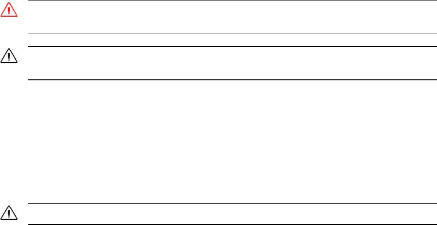
The Trimble R10 GNSS receiver
The Trimble R10 GNSS receiver incorporates a GNSS antenna, receiver, internal radio, and battery in
a rugged light-weight unit that is ideally suited as an all-on-the-pole RTK rover or quick setup/rapid
mobilization base station. LEDs enable you to monitor satellite tracking, radio reception, data
logging status, Wi-Fi status, and power. Bluetooth wireless technology provides cable-free
communications between the receiver and controller.
You can use the receiver as part of an RTK GNSS system with the Trimble Access™ software. The
receiver can optionally record GNSS data to the receiver’s internal memory and download to a
computer or USB flash memory stick.
The receiver has no front panel controls for changing settings. To configure the receiver, use the
web interface which is available by connecting to the receiver’s Wi-Fi via a PC or a smartphone.
Trimble R10 GNSS Receiver User Guide 11

Features
The Trimble R10 GNSS receiver has the following features:
lSmall, lightweight design – 1.12 kg (2.49 lb) (integrated radio, GNSS receiver, GNSS antenna and
battery); 3.57 kg (7.86 lb) complete system weight (rover including TSC3 controller and rod)
lThe quick setup, high mobility base or rover receiver, is ideal for any size jobsite as a rover and
for working on multiple jobsites on a daily or weekly basis
l440-channel, Trimble 360 receiver, fully future-proof signal tracking of current GNSS systems:
l lGPS: L1C/A, L1C, L2C, L2E, L5
lGLONASS: L1C/A, L1P, L2C/A, L2P, L3
lSBAS: L1C/A, L5
lGalileo: E1, E5a, E5B
lBeiDou: B1, B2
lMeasure points sooner, faster and in harsh environments with HD-GNSS™
lIncreased productivity and measurement traceability with Surepoint™ auto-tilt compensation
technology
lCapable of tracking the CenterPoint™ RTX® correction service using satellite delivery
lReduced downtime due to loss of radio signal with Trimble xFill™ service
lCapable of tracking all OmniSTAR® signals
lPerforms all site measurement and stakeout operations within the operating range of the radio
lInternal, removable, smart Lithium-ion battery provides up to 5+ hrs GNSS rover operation per
battery
lBluetooth wireless technology for cable free, no hassle, base or rover operation
lSimple keypad with on/off key and LED indicators for power, radio, Wi-Fi, and satellite tracking
l20 Hz update rate
lFull base/rover interoperability
lOperates within a VRS™ network for conventional base station-free rover capability
lFully integrated 3.5G UMTS cellular modem
lIntegrated receive and transmit radio
lCapable of tracking all SBAS systems
Trimble R10 GNSS Receiver User Guide 12
Parts of the receiver
All operating controls are located on the front panel. Serial ports and connectors are located on the
bottom of the unit.
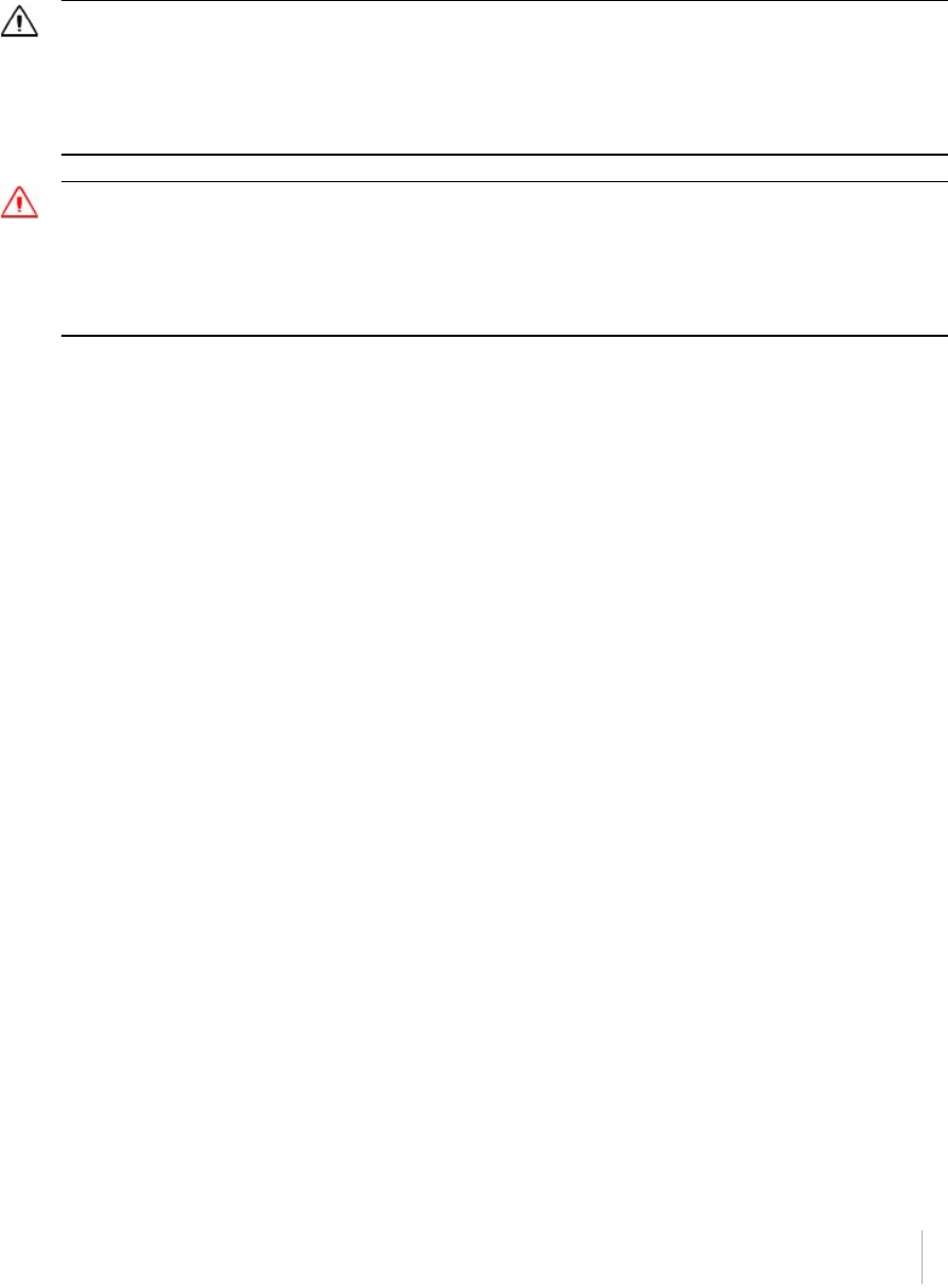
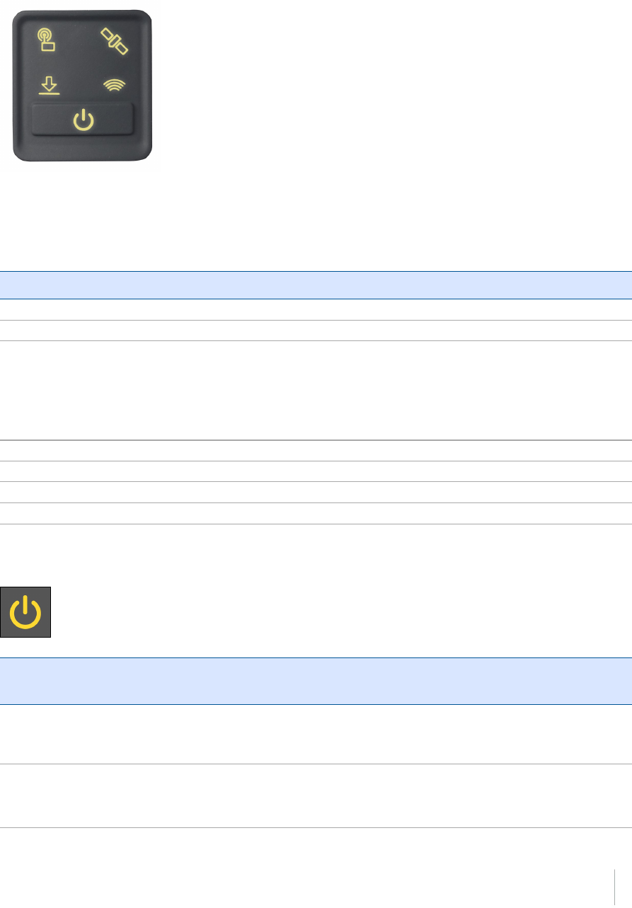
Front panel
The following figure shows a front view of the receiver. The front panel contains the four indicator
LEDs and the Power button with LED.
The Power button controls the receiver’s power on or off functions.
The indicator LEDs show the status of data logging/downloading, power, satellite tracking,
Bluetooth/Wi-Fi, and radio transmit/receive.
For more information, see Button and LED operations, page 26.
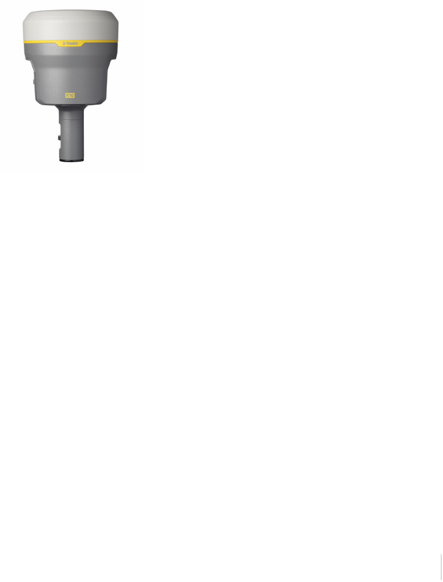
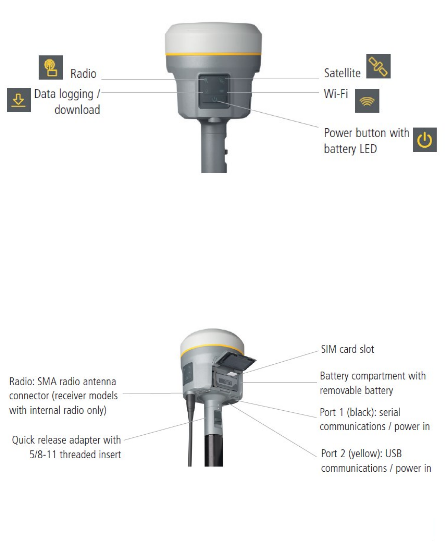
Lower housing
The lower housing contains the two communication and power ports, one TNC radio antenna
connector, and the Quick Release Socket.
Trimble R10 GNSS Receiver User Guide 13
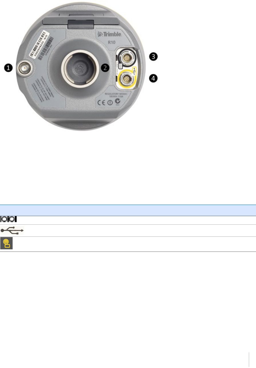
❶SMA Connection: UHF/VHF antenna
❷Quick Release socket
❸Lemo Port 1: Serial connection
❹Lemo Port 2: USB connection
Receiver ports
Icon Name Connections
Port 1 Device, computer, external radio, power in, power out
Port 2 Device, computer, USB flash memory stick, power in
RADIO Radio communications antenna
Trimble R10 GNSS Receiver User Guide 14

Port 1 is a 7-pin 0-shell Lemo connector that supports RS-232 communications and
external power input. Port 1 has no power outputs.
Port 2 is a 7-pin 0-shell Lemo connector that allows for USB 2.0 communications and
external power input. For more information, see Default receiver settings, page 34.
The SMA port connector is for connecting a radio antenna to the receiver internal
radio. A whip “rubber duck” antenna is supplied with the system for units with
internal UHF or VHF MHz radios. This connector is not used if you are using an
external UHF/VHF radio. For longer range operation (to provide higher gain and to
raise the antenna higher above the ground), you can use a cable to connect an
external radio antenna to the SMA port. For more information, refer to the
"Connecting the receiver to external devices" topic in the Web Help.
Trimble R10 GNSS Receiver User Guide 15
Batteries
The receiver has one rechargeable Lithium-ion battery, which can be removed for charging. You can
also connect the receiver to an external power source through Port 1 or Port 2.
During measurement operations, the internal battery typically provides about 5.5 hours of power if
using the internal Rx (receive) radio and about 4.5 hours operating as a base station using the
internal 450 MHz Tx (transmit at 0.5 watt) radio. These times vary according to the type of
measurement and the operating conditions.
Battery safety
Charge and use the battery only in strict accordance with the instructions provided.
WARNING – Do not damage the rechargeable Lithium-ion battery. A damaged battery can cause an explosion or
fire, and can result in personal injury and/or property damage.
To prevent injury or damage:
– Do not use or charge the battery if it appears to be damaged. Signs of damage include, but are not limited to,
discoloration, warping, and leaking battery fluid.
– Do not expose the battery to fire, high temperature, or direct sunlight.
– Do not immerse the battery in water.
– Do not use or store the battery inside a vehicle during hot weather.
– Do not drop or puncture the battery.
– Do not open the battery or short-circuit its contacts.
WARNING – Avoid contact with the rechargeable Lithium-ion battery if it appears to be leaking. Battery fluid is
corrosive, and contact with it can result in personal injury and/or property damage.
To prevent injury or damage:
– If the battery leaks, avoid contact with the battery fluid.
– If battery fluid gets into your eyes, immediately rinse your eyes with clean water and seek medical attention.
Do not rub your eyes!
– If battery fluid gets onto your skin or clothing, immediately use clean water to wash off the battery fluid.
Connecting the receiver to a vehicle battery
WARNING – Use caution when connecting battery cable's clip leads to a vehicle battery. Do not allow any metal
object or jewelry to connect (short) the battery's positive (+) terminal to either the negative (-) terminal or the
metal of the vehicle connected to the battery. This could result in high current, arcing, and high temperatures,
exposing the user to possible injury.
WARNING – When connecting an external battery, such as a vehicle battery, to the receiver, be sure to use the
Trimble cable with proper over-current protection intended for this purpose, to avoid a safety hazard to the user
or damage to the product.
Trimble R10 GNSS Receiver User Guide 16
Wet locations
WARNING – This product is not intended to be used outdoors or in a wet location when it is powered by the
external power supply. The connection is not waterproof and could be subject to electrical shorting.
WARNING – The external power adaptor and its associated power cord and plug are not intended to be installed
outdoors, or in a wet location.
Charging the Lithium-ion battery
The rechargeable Lithium-ion battery is supplied partially charged. Charge the battery completely
before using it for the first time. Charging takes approximately 3 hours per battery at room
temperature. If the battery has been stored for longer than three months, charge it before use.
WARNING Charge and use the rechargeable Lithium-ion battery only in strict accordance with the instructions.
Charging or using the battery in unauthorized equipment can cause an explosion or fire, and can result in personal
injury and/or equipment damage.
To prevent injury or damage:
– Do not charge or use the battery if it appears to be damaged or leaking.
– Charge the Lithium-ion battery only in a Trimble product that is specified to charge it. Be sure to follow all
instructions that are provided with the battery charger.
– Discontinue charging a battery that gives off extreme heat or a burning odor.
– Use the battery only in Trimble equipment that is specified to use it.
– Use the battery only for its intended use and according to the instructions in the product documentation.
To charge the battery, first remove the battery from the receiver, and then place it in the battery
charger, which is connected to AC power.
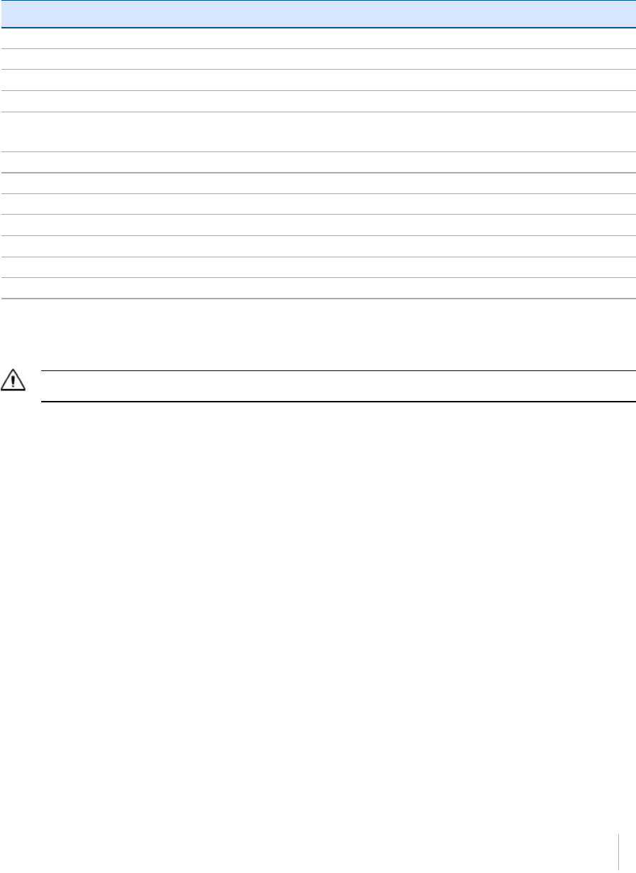
Battery charger
The charger can charge three types of Lithium-ion batteries. It can be powered by AC power or
vehicle battery.
Trimble R10 GNSS Receiver User Guide 17

The Charger Kit Dual Slot consists of:
lCharger dual-battery slot (P/N 53018010)
lPower supply for charger (P/N 55001403, Japan: P/N 78650)
lCable Kit-AC for power supply (P/N 55001402; Japan: P/N 78656)
lCharger battery slot insert (P/N 89843-00)
Chargeable batteries
The charge can charge the following types of batteries:
lLithium-ion Rechargeable Battery (Smart Battery), 3.7 Ah, 7.4 V, (P/N 76767, P/N 89840-00)
lLithium-ion Rechargeable Battery, 2.6 Ah, 7.4 V, P/N 92600 (remove battery slot inserts to
charge this type of battery)
lLithium-ion Rechargeable Battery, 4,4 Ah, 11.1.V, P/N 49400 (remove battery slot inserts to
charge this type of battery)
Charger slots
The charger has two slots. Each slot can charge either type of battery. When charging the smart
battery, you must place the inserts into the battery slot before inserting the battery. Batteries are
charged sequentially. Beside each slot are two LED indicators (red and green) to indicate the battery
status.
Power supply
The charger can be powered by AC power (using the power supply for the charger) or by car voltage
using a 12V vehicle adapter for dual battery charger (P/N 89844-00, not included with receiver kit).
AC power supply is an external adapter, usable worldwide. Different cords with appropriate plugs for
different countries are supplied with adapter.
Vehicle power
The charger can be powered by vehicle voltage of nominal 12 V. It can withstand voltages of a
vehicle voltage of nominal 24 V (maximum 32 V). So if the user connects the vehicle cable by mistake
to a 24 V socket in a vehicle the charger does not start charging but latches in fault condition and
flashes all green LEDs. The power must be removed to reset the fault condition.
Trimble R10 GNSS Receiver User Guide 18
Technical data
Power Supply Receiver Connection
AC Input Voltage 100 to 240 V AC +/-10%
AC Frequency 50 to 60 Hz
DC Output Voltage 19 V
DC Output current charger Approx. 3.5 A
DC Power Input Voltage operation 10 V to 21 V
Unit switches off if voltage is out of range
DC Power Input Voltage limits 8 V to 32 V
Absolute maximum input voltage 32 V
Over voltage 21 V to 32 V
Working voltage 10 V to 21 V
Under voltage charging <10 V
Sum of charge time for all batteries 5 to 6 hours
Charger in first hour >60%
Charging the battery
Caution – Ensure that nothing obstructs the vents in the back and bottom of the charger.
The battery is supplied partially charged. Charge the battery completely before using it for the first
time.
lTo charge the battery, use only a charger that Trimble recommends for charging the Lithium-
ion battery.
lIf the equipment has been stored for longer than three months, charge the battery before
using the receiver.
The charger operates between 0 °C (32 °F) and 40 °C (104 °F). Charging a battery at temperatures in
the range of 0 °C (32 °F) to 5 °C (41 °F) will take longer than charging at room temperature.
To charge the battery:
1. Ensure that the vents in the back and bottom of the charger are unobstructed.
2. Place the charger on a hard, flat and level surface, to ensure that there is airflow under the
charger.
3. To apply power to the charger, use the AC to DC converter or 12 V vehicle adapter. The charger
scans the slots for a battery.
4. Place the battery in any of the slots. The red light turns off (can take up to 5s). For an
Trimble R10 GNSS Receiver User Guide 19
explanation of the LED, see LED Status Indicator below.
5. Charging takes approximately 3 hours per battery at room temperature. If several batteries are
charging in the battery charger, the batteries will be charged sequentially, from left to right.
Leave a deeply discharged or shorted battery overnight in the charger to attempt to revive the
battery. A shorted battery is typically revived as soon as the slot is scanned. If the red LED turns off,
the battery is revived. If the red LED stays on, the battery is no longer functional and needs to be
replaced.
LED status indicator
Beside each slot are two LED indicators (Red and Green) to display the battery status:
Status Red Green
No battery detected (no battery present or battery
defect)
On Off
Battery detected (charging not started yet)
- Conditioning not required
- Conditioning required
Off
Blinking
Off
Off
Charging in progress
- Conditioning not required
- Conditioning required
- Over/under temperature (charge is inhibited)
Off
Blinking
One flash every 2.5
seconds
Off
Blinking
Blinking
Conditioning in progress On Blinking
Conditioning done (battery fully charged) On On
Battery fully charged
- Conditioning not required
- Conditioning required
Off
Blinking
On
On
Power supply over/under voltage Off One flash every 2.5
seconds
Trimble R10 GNSS Receiver User Guide 20
Troubleshooting
Issue Solution
Battery is not detected (Red LED
does not turn off)
The battery is not properly inserted. Reinsert battery into
battery charger slot.
Battery contacts contaminated. Clean the battery (for example, by inserting and removing the
battery several times) or replace the battery.
Deeply discharged. Leave the battery overnight in the charger to attempt to revive
the battery.
Battery defective. Replace the battery.
Storing the Lithium-ion battery
Do not store batteries in the receiver or in the external charger unless power is applied.
Keep all batteries on continuous charge when not in use. You can keep batteries on charge
indefinitely without damage to the batteries.
Disposing of the rechargeable Lithium-ion battery
Discharge a Lithium-ion battery before disposing of it. Dispose of batteries in an environmentally
sensitive manner, and adhere to any local and national regulations concerning battery disposal or
recycling.
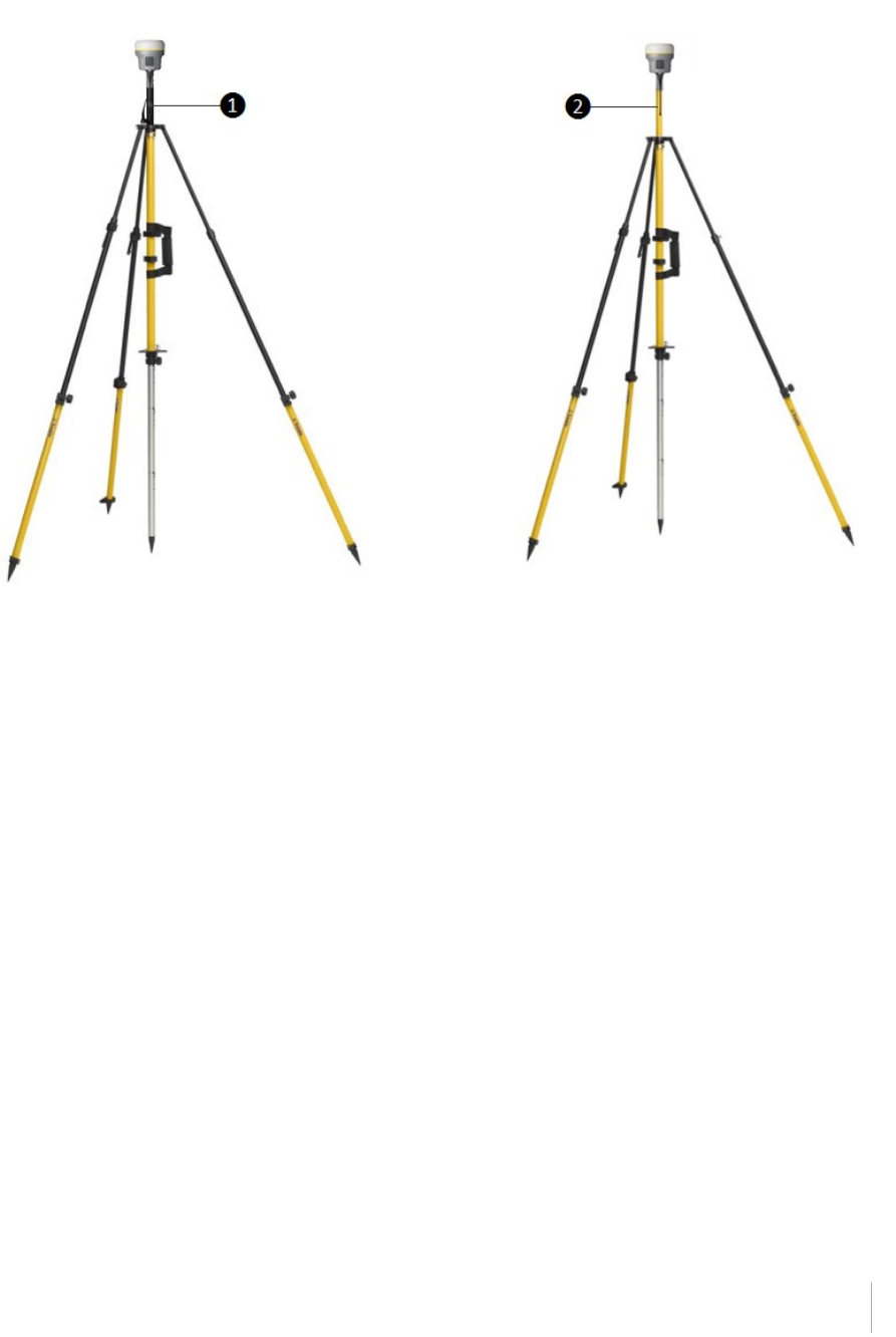
Inserting the battery and SIM card
Align the arrows and on the battery and battery compartment and then insert the battery as
indicated in the images below.
To remove the battery, slide the battery bail to the left.
Note – The gasket on the inside of the battery door should be clean of any dirt or dust to ensure
proper sealing of the battery compartment.
Trimble R10 GNSS Receiver User Guide 21
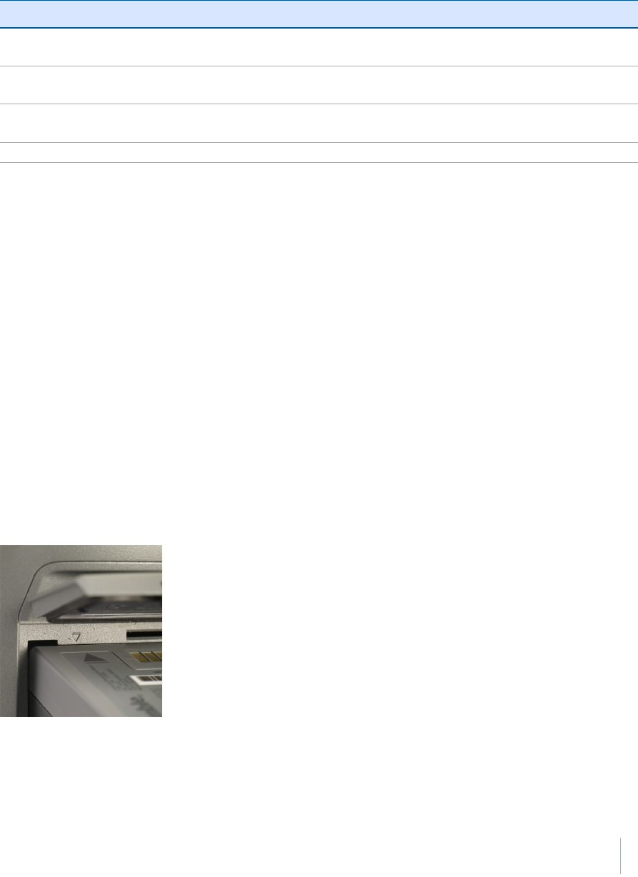
Insert the SIM card with the contacts facing upward, as indicated by the SIM card icon next to the
SIM card slot.
To eject the SIM card, slightly push it in to trigger the spring-loaded release mechanism.
Tip – The SIM card is provided by your cellular network service provider.
Accessories
Attaching the quick release adapter
Push down the spring-loaded button of the quick release adapter and then align the white dots on
the bottom of the receiver and the quick release adapter. Slide in the quick release adapter and then
release the button.
Trimble R10 GNSS Receiver User Guide 22
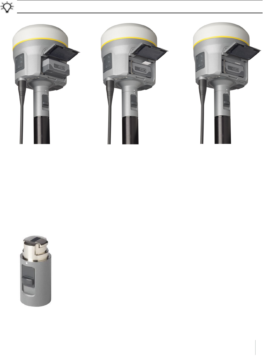
Height measurement methods
The following antenna height measurement methods are available in the field/office software and
web interface:
❶ Bottom of antenna mount
❷ Bottom of quick release
❸ Lever of R10 extension
Note – For information on using the Trimble R10 receiver with the Trimble V10 Imaging Rover, refer
to the Trimble V10 User Guide.
Trimble R10 GNSS Receiver User Guide 23
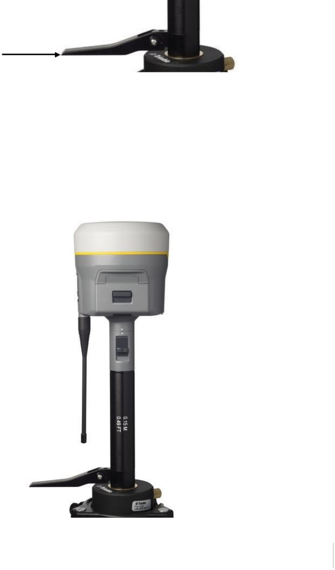
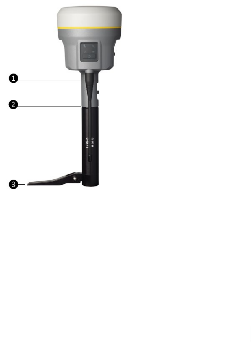
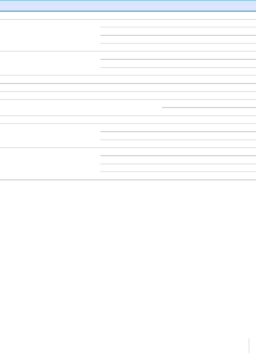
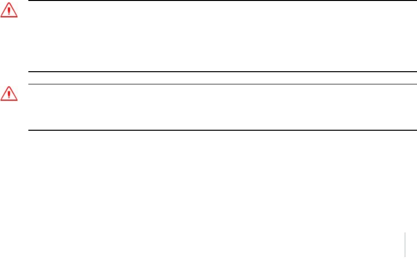
Base station extension with measurement lever
The Trimble R10 GNSS receiver uses a base station extension pole that increases the height of the
receiver to allow clearance for the 450 MHz internal radio antenna and also allows for easy and
accurate measurement of the base station antenna height. The extension pole includes a height
measurement lever with a defined measurement point:
To measure the height of the base station extension with measurement lever, measure the slant
height from the control point on the ground to the height measurement point on the lever. Enter
the slant height into the field software (or web interface) and then select the Lever of R10 extension
measurement method. The field software (or web interface) automatically calculates the antenna
height from the slant height. The base station extension with measurement lever should be used
when setting up a base station or static session on an extension leg tripod with tribrach.
The illustration below shows the Trimble R10 GNSS receiver with base station extension with
measurement lever (P/N 89846-00):
Trimble R10 GNSS Receiver User Guide 24
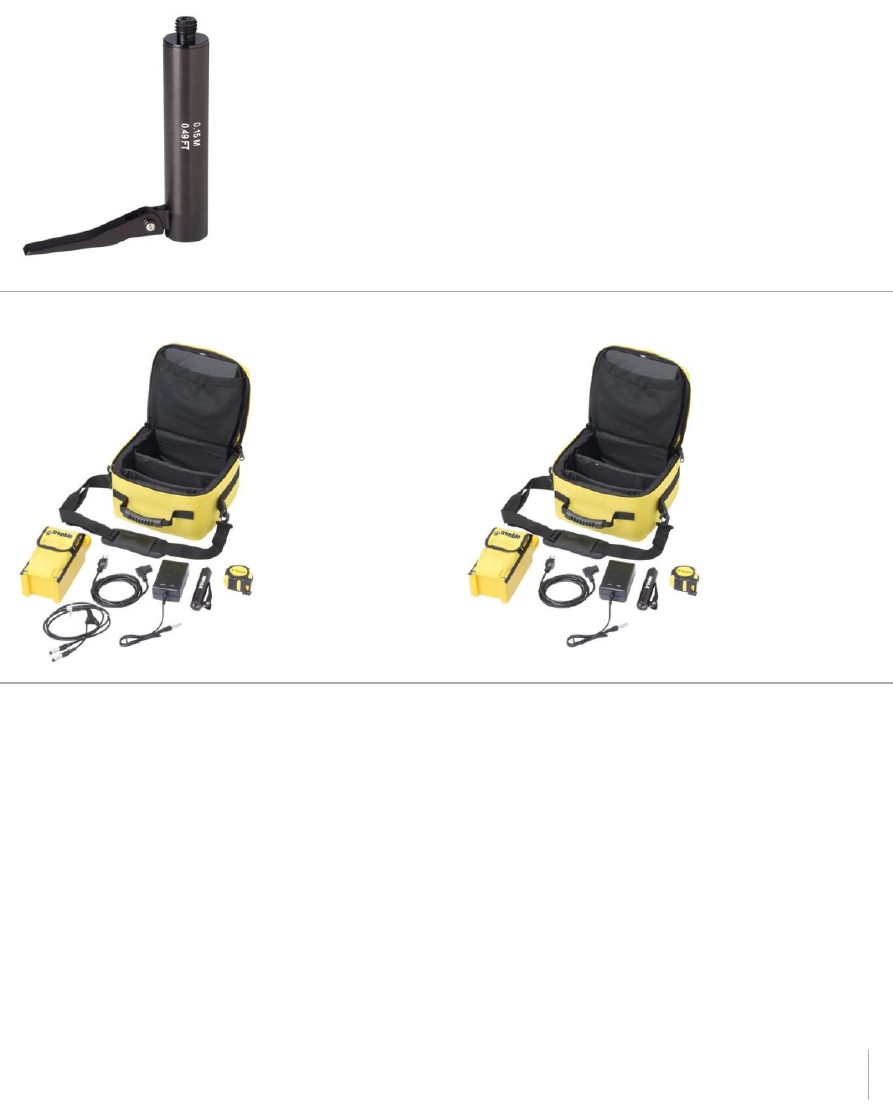
The Base Station Extension with Measurement Lever is available as a standalone accessory
(P/N 89846-00) or within the Base Kit or Post processed (PP) Kit.
Note – Measuring to the measurement lever is not required when using a fixed height tripod. If the
base station extension with measurement lever is used with a fixed height tripod, the height of the
extension pole (0.15 m (0.49 ft)) should be added to the height of the fixed height tripod and the
measurement method “bottom of quick release” used.
Base Extension with Measurement Lever (P/N 89846-00):
Base Kit (P/N 89861-00): PP Kit (P/N 89862-00):
Note – Measuring to the measurement lever is not required when using a fixed height tripod. If the
base station extension with measurement lever is used with a fixed height tripod, the height of the
extension pole (0.15 m (0.49 ft)) should be added to the height of the fixed height tripod and the
measurement method “bottom of quick release” used.
Trimble R10 GNSS Receiver User Guide 25
Button and LED operations
The LEDs on the front panel indicate various operating conditions. Generally, a lit or slowly flashing
LED indicates normal operation, a LED that is flashing quickly indicates a condition that may require
attention, and an unlit LED indicates that no operation is occurring. The following table defines each
possible LED state:
The term... means that the LED...
Very slow flash is off and on equally with a 1.5 second cycle.
Slow flash alternates on/off every ½ second.
Radio slow flash is off longer than it is on when the receiver is receiving
corrections. The receiver repeats this cycle typically once per
second.
is on more than off when the receiver is transmitting corrections.
The receiver repeats this cycle typically once per second.
Medium flash is off and on equally more than once per second.
Fast flash alternates rapidly on/off every 1/10 of a second.
On is lit steady.
Off is unlit.
Power button
Action Power
button
Description
Turn on
the
receiver
Press (see
the note
below)
All four LEDs light up and remain lit for 3 seconds. Then all LEDs go off and
then the power LED immediately comes back on.
Turn off
the
receiver
Hold for 2
seconds
and then
When holding down the Power button; the battery LED remains on. The
Satellite LED turns constant and then turns off after 2 seconds.
After releasing the power button, the battery LED stays lit for about 5
Trimble R10 GNSS Receiver User Guide 26
Action Power
button
Description
release seconds and then all LEDs go blank.
Clear the
ephemeris
file and
reset the
receiver to
the factory
defaults
Hold for
15
seconds
The Radio, Wi-Fi, and Satellite LEDs turn off after 2 seconds. The battery LED
remains on. After 15 seconds, the Satellite LED comes on to indicate that it is
time to release the Power button. Upon restart, the Wi-Fi will also turn on in
Access Point mode.
Delete
application
files and
data
logging
files
Hold for
30
seconds
The Radio, Wi-Fi, and Satellite LEDs turn off after 2 seconds. After 15 seconds,
the Satellite LED comes on and stays on for 15 seconds, then turns off to
indicate that it is time to release the Power button. The receiver then
restarts.
Note – The term “press” means to press the button and release it immediately. The term “hold”
means to press the button and hold it down for the given time.
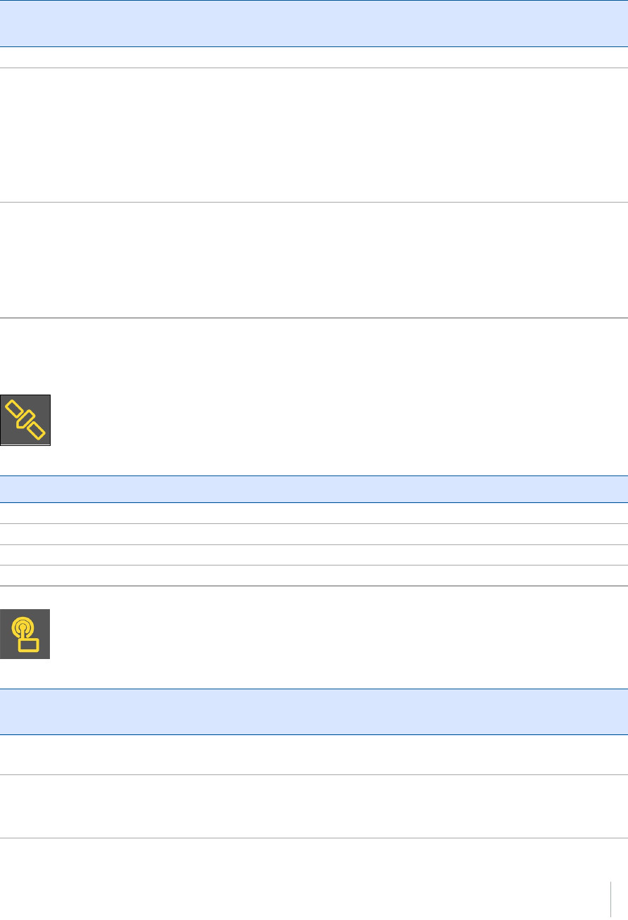
Satellite LED
Receiver mode Satellite LED Amber
No satellites tracked Off
Boot up or when in Monitor mode On
Tracking fewer than 4 SVs Fast flash
Tracking more than 4 SVs Slow flash
Radio LED
Radio
mode
Radio
LED Amber
Description
No receive
or transmit
Off
Receive Radio slow flash See the table at the top of this topic.
This LED also flashes when using the Wi-Fi only for receiving
corrections.
Trimble R10 GNSS Receiver User Guide 27
Radio
mode
Radio
LED Amber
Description
Transmit Radio slow flash See the table at the top of this topic.
This LED also flashes when using the Wi-Fi only for transmitting
corrections
Wi-Fi LED
Receiver mode Wi-Fi LED Amber
Wi-Fi off Off
Wi-Fi is access point (base mode/sending corrections) Medium flash
Wi-Fi is client (and not connected to an access point) Off
Wi-Fi as client (rover mode receiving corrections) Very slow flash
Data logging/downloading LED
Receiver mode Data LED Amber
Data logging off Off
Data logging on On
Downloading to USB flash memory stick Slow flash
Full USB flash memory stick detected Fast flash
Download to USB flash memory stick complete Very slow flash
Trimble R10 GNSS Receiver User Guide 28
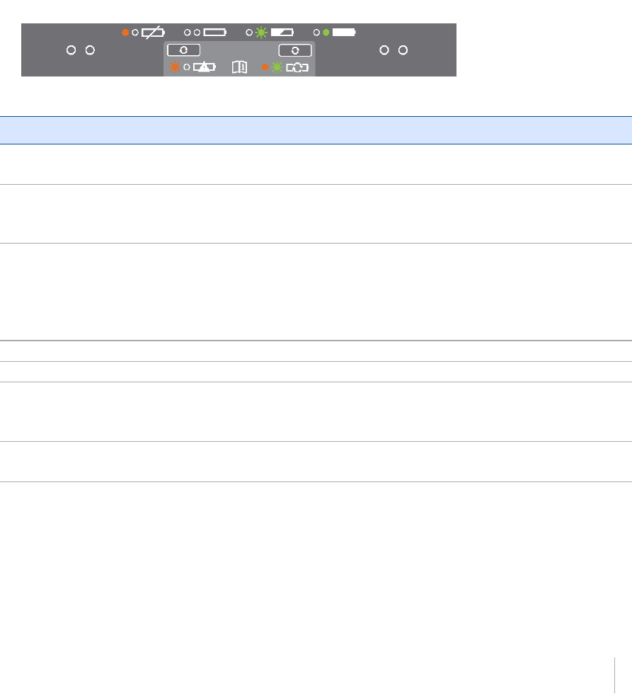
LED flash patterns
The following table details the possible flash patterns to indicate various states of receiver
operation.
Receiver mode Power
button
Radio LED Satellite
LED
Data LED Wi-Fi
LED
Receiver OFF OFF OFF OFF OFF OFF
Receiver ON, healthy power ON N/A N/A N/A N/A
Low power Fast flash N/A N/A N/A N/A
Transmitting correction messages N/A Flashes off when
transmitting
N/A N/A N/A
Receiving valid data packets N/A Slow flash N/A N/A N/A
Tracking fewer than 4 SVs ON N/A Fast
flash
N/A N/A
Tracking more than 4 SVs ON N/A Slow
flash
N/A N/A
Logging data internally N/A N/A N/A Solid N/A
Transferring data to flash memory stick N/A N/A N/A Slow flash N/A
All data transferred to flash memory stick N/A N/A N/A Very slow
flash
N/A
Flash memory stick full N/A N/A N/A Fast flash N/A
Wi-Fi configured as an access point N/A N/A N/A N/A Slow
flash
Wi-Fi configured as a client N/A N/A N/A N/A On
Receiver in monitor mode (loading
firmware from WinFlash)
ON Slow flash Solid OFF OFF
Note – If a column shows “N/A”, that specific LED may or may not be on, but it is not relevant to
that particular mode.
Trimble R10 GNSS Receiver User Guide 29
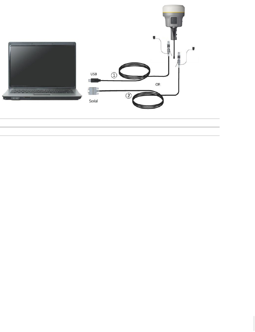
Connecting to an office computer
The receiver can communicate with the office computer using a serial connection by either using a
serial cable (P/N 89851-00 or P/N 59046), or by using the USB cable (P/N 89852-00 or P/N 80751) and
then Configuring a PC USB port as a virtual serial port, page 70. Before you connect to the office
computer, ensure that the receiver battery is fully charged.
The following figure shows how to connect to the computer for serial data transfer:
①USB cable (P/N 89852-00 or 80751)
②Serial cable (P/N 89851-00 or P/N 59046)
Trimble R10 GNSS Receiver User Guide 30
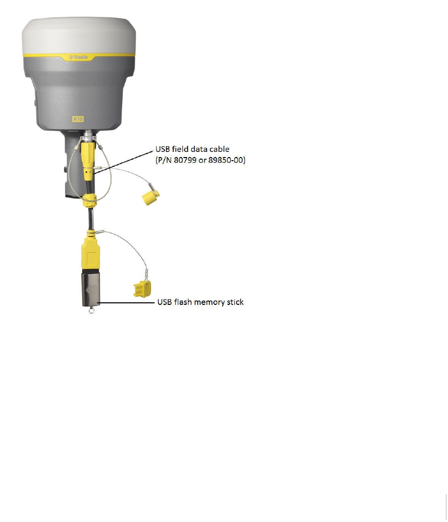
Connecting to a USB flash memory stick
The receiver can download logged data directly to a USB flash memory stick using the supplied USB
field data cable (P/N 80799 or 89850-00). After the cable is connected to the receiver’s port 2 (USB)
and the flash memory stick attached, the receiver will download all logged files to the flash memory
stick.
Note – The USB field data cable is used to download logged (existing) data files from the receiver
memory to the flash memory stick. The USB field data cable cannot be used to log data files
directly to the flash memory stick.
The following figure shows a flash memory stick connected to the receiver using the USB download
cable:
Trimble R10 GNSS Receiver User Guide 31

Configuring a PC USB port as a virtual serial port
It is possible to use the USB interface from a Trimble R10 GNSS receiver with a software application
that requires a serial port.
For example, the Trimble WinFlash utility can be run on a computer that has no physical serial port
by connecting the USB cable between the computer and the receiver.
Windows 7 Professional operating system
1. The simplest way to install the virtual serial port for the USB interface to the receiver is to go to
the Trimble Support website (www.trimble.com/support) and search for the Trimble R10 GNSS
receiver. In the Downloads section, download the file called Windows7 USB Installer to your
computer.
This file contains a Support Note and installation program.
2. Run the installation program. It will load the virtual serial port for the USB interface on your
computer.
Note – If you have installed the Trimble WinFlash utility (www.trimble.com/support) on your
computer, then another way to install the virtual serial port for the USB interface is to run the
USB Installer program, which is located in C:\Program Files\Common Files\Trimble\USBDriver.
If this process does not work for your computer, or if you have a different Windows operating
system on your computer, then follow the procedure below.
Windows Vista and Windows 7 operating system
1. Go to the Trimble Support website (www.trimble.com/support) and search for the receiver you
have. In the Support Notes section, download the file called R10 GNSS Interface to a Virtual
COM port on a Computer to your computer.
2. Open the file and place the trmbUsb.inf file in a temporary folder on your computer.
3. On the computer, select Control Panel / Device Manager.
4. Click on the name of the computer and then from the Action menu, select Add Legacy Driver.
5. A wizard prompts you to locate the TrimbleUsb.inf file. Locate the file and then follow the
prompts in the wizard to continue.
Windows XP operating system
1. Go to the Trimble Support website (www.trimble.com/support) and search for the Trimble R10
GNSS receiver. In the Support Notes section, download the file called R10 GNSS Interface to a
Virtual COM port on a Computer to your computer.
2. Open the file and place the trimble.Usb.INF file in a temporary folder on your computer.
3. Turn on the receiver and then connect the USB cable to the computer. The New Hardware
Trimble R10 GNSS Receiver User Guide 32

wizard appears.
4. Select the No, not this time option and then click Next.
5. A dialog prompts you to specify the location of the USBSer.sys file. For example,
C:\Windows\System32\Drivers.
6. On some computers you may need to repeat Step 4 for the TrimbleUsb.inf file.
7. Check that the receiver is available for use. Go to the Device Manager menu on the computer.
The receiver should appear in the Ports list.
Note – If you are running an application such as WinFlash software on the computer and you
physically disconnect the USB cable from the computer and then reconnect it, it does not always
re-establish the connection. This is because opening the serial port from the application locks the
device handle and when the USB device is disconnected, the application does not close the serial
port and the device handle is still locked. On reconnecting, the USB cable is unable to get the device
handle since it is locked. You must close the application before the reconnect to the port will work.
This limitation is due to the behavior of the Microsoft USB serial driver.
Logging data
Data logging involves the collection of GNSS measurement data over a period of time at a static
point or points, and subsequent postprocessing of the information to accurately compute baseline
information. Data logging using receivers requires access to suitable GNSS postprocessing software
such as the Trimble Business Center software.
Postprocessed GNSS data is typically used for control network measurement applications and
precise monitoring. GNSS measurement data is collected over a period of time at a static point or
points and then postprocessed to accurately compute baseline information.
Logging data after a power loss
If power is unexpectedly lost while the receiver is logging data, the receiver tries to return to the
state it was in immediately before the power loss. The receiver does not reset itself to default
settings.
If the receiver was logging data when power was lost, it resumes logging data when power is
restored.
Trimble R10 GNSS Receiver User Guide 33
Default receiver settings
These settings are defined in the default application file.
Function Settings Factory default
SV Enable - All SVs enabled
General Controls Elevation mask 10°
PDOP mask 25
RTK positioning mode Low Latency
Motion Kinematic
Serial Port 1 Baud rate 38,400
Format 8-None-1
Flow control None
Serial Port 2 USB
Input Setup Station Any
NMEA/ASCII (all supported messages) All ports Off
Streamed Output All types Off
Offset=00
RT17/Binary All ports Off
Reference Position Latitude 0°
Longitude 0°
Altitude 0.00 m HAE
Antenna Type Trimble R10 GNSS receiver, Internal
Height (true vertical) 0.00 m
Group All
Measurement method Antenna Phase Center
Trimble R10 GNSS Receiver User Guide 34


2 Base Station Operation
Base station operation guidelines
This topic introduces the concept of base station operation, provides information to help you
identify good setup locations, describes best practices for setting up the equipment, and outlines
the precautions that you need to take to protect the equipment.
Real-Time Kinematic (RTK) operation provides centimeter-level precision by eliminating errors that
are present in the GNSS system. For all RTK operations, you require both a rover receiver and a
source of corrections from a base station or network of base stations.
A base station consists of a receiver that is placed at a known (and fixed) position. The receiver
tracks the same satellites that are being tracked by the rover receiver, at the same time that the
rover is tracking them. Errors in the GNSS system are monitored at the fixed (and known) base
station, and a series of position corrections are computed. The messages are sent through a radio
link to the rover receiver, where they are used to correct the real time positions of the rover.
Base station components
The base station has the following components:
lGNSS receiver
lGNSS antenna
lHeight extension pole with measurement level
lBase station radio and antenna
lPower source
GNSS receiver and GNSS antenna
The base station GNSS receiver can be one of following types:
lAn integrated receiver that incorporates a GNSS receiver, GNSS antenna, power source, and
radio into a single compact unit. An integrated GNSS antenna can be rapidly set up on a tripod,
fixed height tripod, or T-Bar anywhere that is convenient on the jobsite.
lA modular receiver that incorporates a GNSS receiver and separate GNSS antenna. The GNSS
antenna (and, optionally, the base station radio antenna) is separate from the receiver.
Because the GNSS antenna is separate, you can use the following optimized components:
n na geodetic antenna with large ground plane, to eliminate multipath (the major source of
GNSS errors) at the base station
na high-gain or directional radio antenna, to increase broadcast range and to provide
maximum coverage
You can place a modular receiver in an easily accessible and secure location, safe from theft and the
weather, while the antennas are placed high on a tower or building, clear of obstructions and able to
deliver maximum performance.
Trimble R10 GNSS Receiver User Guide 36

2 Base Station Operation
You can use either type of receiver in a permanent, semi-permanent, or daily quick setup
configuration. If semi-permanent or permanent operation is required, however, the modular
receiver delivers significant advantages.
Base station setup guidelines
For good performance, observe the following base station setup guidelines:
lPlace the GNSS receiver in a location on the jobsite where equal range in all directions provides
full coverage of the site. This is more important on larger jobsites, where the broadcast range of
the base station radio may limit the operations of the system.
lPlace the GNSS antenna in a location that has a clear line of sight to the sky in all directions. Do
not place the antenna near vertical obstructions such as buildings, deep cuttings, site vehicles,
towers, or tree canopy.
lPlace the GNSS and radio antennas as high as practical. This minimizes multipath from the
surrounding area, and enables the radio to broadcast to the maximum distance.
Note – The GNSS antenna must have a clear line of sight to the sky at all times during
operation.
lChoose the most appropriate radio antenna for the size and footprint of the site. The higher
the gain on the antenna, the longer the range. If there is more focus on the transmission signal,
there is a reduced coverage area. A 5 db gain antenna provides a mix of good range and
reasonable directional coverage.
Note – A 5 db gain antenna with remote mount and cable is available as an accessory for the
internal radio.
lMake sure that the GNSS receiver does not lose power. To operate continuously for more than
a few hours without loss of power at the base station, provide external power. Sources of
external power include:
n nAC power
n12 V vehicle battery
nTrimble custom external battery pack
nGenerator power
nSolar panel
When you use an external power supply, the integrated battery provides a backup power
supply, enabling you to maintain continuous operation through a mains power failure.
lDo not locate a GNSS receiver, GNSS antenna, or radio antenna within 400 meters (about 1,300
feet) of:
n na powerful radar, television, or cellular communications tower
nanother transmitter
nanother GNSS antenna
Trimble R10 GNSS Receiver User Guide 37

2 Base Station Operation
Cell phone towers can interfere with the base station radio broadcast and can stop
corrections from reaching the rover receiver. High-power signals from a nearby radio or
radar transmitter can overwhelm the receiver circuits. This does not harm the receiver, but
can prevent the receiver electronics from functioning correctly.
Low-power transmitters, such as those in cell phones and two-way radios, do not interfere
with receiver operations
lDo not set up the base station directly beneath or close to overhead power lines or electrical
generation facilities. The electromagnetic fields associated with these utilities can interfere with
GNSS receiver operation. Other sources of electromagnetic interference include:
n nGasoline engines (spark plugs)
nTelevisions and computer monitors
nAlternators and generators
nElectric motors
nEquipment with DC-to-AC converters
nFluorescent lights
nSwitching power supplies
lPlace the GNSS receivers in a protected and secure location. If the base station is in the center
of a jobsite where heavy machinery is operating, place flags around the base station to warn
operators of its existence.
lIf you place the receiver in a lock box on the jobsite to protect the receiver from theft or from
the weather, shield the lock box from direct sunlight and provide ventilation for the receiver
through an inlet and extractor fan. A receiver that has a broadcast radio generates significant
heat. Do not allow the temperature in the box to exceed 50 °C (122 °F).
If working in a cold climate, you may need to provide heat to the receiver. Do not operate the
receiver below –40 °C (–40 °F)
lTrimble recommends that, wherever possible, you keep GNSS receiver equipment dry. The
receivers are designed to withstand wet weather, but keeping them dry prolongs their life and
reduces the effects of corrosion on ports and connectors. If the equipment gets wet, use a
clean dry cloth to dry the equipment and then leave the equipment open to the air to dry. Do
not lock wet equipment in a transport case for prolonged periods. Avoid exposing the receiver
to corrosive liquids and salt water wherever possible.
lTrimble recommends that you install lightning protection equipment at permanent base
station locations. Equipment should include a gas capsule lightning protector in the GNSS and
radio antenna feed line and appropriate safety grounding. A static dissipater near the antennas
can reduce the likelihood of a direct lightning strike. Also protect any communications and
power lines at building entry points. For more information, contact your local Trimble dealer, or
go to the Huber and Suhner website (www.hubersuhnerinc.com).
lTrimble recommends that you use surge protection equipment on all permanently installed
equipment.
Trimble R10 GNSS Receiver User Guide 38

2 Base Station Operation
Common ways to set up a base station
Trimble recommends that you use a tripod and tribrach setup or a fixed height tripod. The fixed
height tripod is quicker and easier to set up over a control point.
Take great care to ensure that the GNSS antenna is set up accurately over the control point, and
that the GNSS antenna height is measured accurately, in the right way (vertical or slope height) to
the right location on the antenna (base of antenna or to a specified location on the antenna) or
height extension pole with height measurement lever (P/N 89846-00) or Base Station Kit (P/N 89861-
00). When you start the rover receiver, it is important to check in, at one or more known locations,
to check for possible position or height errors. Checking in at a known location is good practice and
can avoid costly errors caused by a bad setup.
Tripod and tribrach setup
In the tripod setup, the tripod is located over the control point, and the tribrach, tribrach adaptor,
and height extension pole with measurement lever is mounted on the tripod and centered over the
point.
1. Mount the quick release adapter onto the height extension pole with measurement lever.
2. Screw the height extension pole with measurement lever into the tribrach. Attach the GNSS
receiver to the quick release adapter.
3. Level and plumb the GNSS receiver over the control point.
4. Measure the height of the base station GNSS antenna by measuring the slant height from the
control point to the measurement lever. Select the “Lever of R10 extension” as the
measurement method when starting the base station. Trimble Access calculates the height to
the Antenna Phase Center (APC) automatically.
5. If required, connect the GNSS receiver to an external 12 V power supply. Use the external
battery cable set (P/N 89864-00) or the Trimble customer 6Ah power pack.
Trimble R10 GNSS Receiver User Guide 39
2 Base Station Operation
Receiver tripod and tribrach setup with an internal 450 MHz Tx radio (Measuring Slant Height)
Fixed height tripod setup
A fixed height tripod setup is similar to a tripod setup, but is simplified by the central leg of the
tripod, which is placed directly on the control point. If the central leg is leveled accurately, the fixed
height tripod is quick and easy to set up, and provides an accurate way to measure the true
antenna height.
1. Screw the quick release adapter onto the tripod head or extension pole used to increase the
height of the receiver above the tripod head.
2. Attach the GNSS receiver to the quick release adapter.
3. Plumb and level the tripod over the control point.
4. Determine the height of the base station GNSS antenna by adding the fixed height of the tripod
from the control point to the tripod head to the height of any extension pole used to increase
the height of the receiver. Select the “Bottom of Quick Release” as the measurement method
when starting the base station. Trimble Access calculates the height to the Antenna Phase
Center (APC) automatically.
5. If required, connect the GNSS receiver to an external 12 V power supply. Use the crocodile clip
cable or the Trimble custom power pack.
Trimble R10 GNSS Receiver User Guide 40
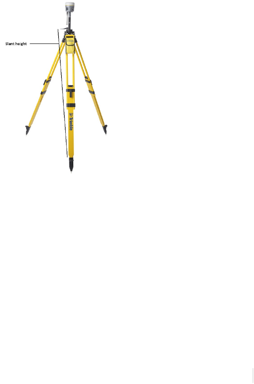
2 Base Station Operation
❶ Base extension with height measurement lever
❷ Standard 20 cm extension pole
Receiver with an internal 450 MHz Transmit radio on a fixed height tripod
Note – Measuring to the measurement lever is not required when using a fixed height tripod. If the
base station extension with measurement lever is used with a fixed height tripod, the height of the
extension pole (0.15m (0.49ft)) should be added to the height of the fixed height tripod and the
measurement method “bottom of quick release” used.
Using a remote radio antenna with the receiver
A remote radio antenna can be used with the Trimble R10 GNSS receiver’s internal 450 MHz radio.
The remote antenna allows the use of a high gain antenna (country dependent) and the ability to
increase the height of the radio antenna for a larger coverage area. The remote antenna cable and
mount, along with the high gain antenna, is available as an accessory for the receiver (P/N 89856-00-
6x Radio frequency dependent).
Typically, the tripod and fixed height tripod methods do not give significant height clearance above
the ground, and can reduce the range of operation caused by radio limitations.
Trimble R10 GNSS Receiver User Guide 41
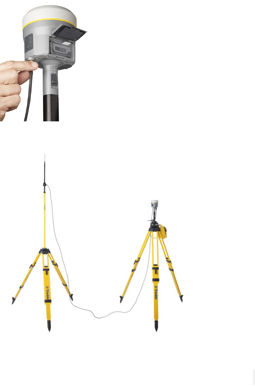
2 Base Station Operation
Connecting remote radio antenna cable to the receiver
Receiver with a remote radio antenna
Trimble R10 GNSS Receiver User Guide 42

2 Base Station Operation
Using an external radio with the receiver
An external radio can be used with the Trimble R10 GNSS receiver. Using a high powered UHF radio
will increase the radio coverage area. The external radio data cable is connected to Port 1 (Serial) on
the receiver.
Outputting corrections using a TDL450/HPB450
radio-modem
The TDL450/HPB450 radio comes with a 5-pin Lemo to 7-pin Lemo connector with a power
connection lead:
1. Connect the 7-pin Lemo connector to the serial port (Port 1) on the receiver.
2. Connect the 5-pin Lemo connector to the TDL450/HPB450 radio.
3. Connect the DC power lead to an external power source.
4. Turn on the TDL450/HPB450 radio.
To configure the system, do one of the following:
lUse the Trimble Access software to connect to the receiver. Set up the base station with the
external radio. The Trimble Access software will locate the TDL450/HPB450 radio and then allow
you to set the radio channel.
lUse the web interface to configure the settings. Select I/O Configuration / Port Configuration.
Select the Serial 1 / Lemo option and select corrections to be sent on the Lemo port at those
baud rate settings (the TDL450/HPB450 serial interface is shipped with the default rates 38400
8/N/1).
Configuration software accompanies the TDL450/HPB450 radio if you need to change the serial
connection baud rate.
Trimble R10 GNSS Receiver User Guide 43

3 Rover Setup and Operation
In this chapter:
nRover operation guidelines
nSurepoint (integrated tilt sensor)
nIntegrated cellular modem
nConnecting the receiver to external devices
nTransferring files directly from the receiver
nDeleting files in the receiver
Trimble R10 GNSS Receiver User Guide 44
3
CHAPTER
3 Rover Setup and Operation
Rover operation guidelines
Real-Time Kinematic (RTK) operation provides centimeter-level precision by eliminating errors that
are present in the GNSS system. For all RTK operations, you require both a rover receiver and a
source of corrections from a base station or network of base stations.
This topic introduces the concept of rover operation, provides information to help you identify
good setup locations, describes best practices for setting up the equipment, and outlines the
precautions that you need to take to protect the equipment.
The second part of the RTK GNSS system is the rover receiver. The rover receiver is moved between
the points that require measurement or stakeout. The rover receiver is connected to a base station
or to a source of RTK corrections such as a VRS system or the Trimble CenterPoint RTX correction
service. The connection is provided by:
lan integrated radio
lan integrated cellular modem
lan integrated Wi-Fi module
la cellular modem in the controller
lan integrated GNSS antenna (L-Band)
In most rover applications, the receiver operates entirely from its own integrated battery unit.
However, you can use an external power supply if one is provided. The internal battery then acts as
an uninterruptible power supply, covering any external power failures.
For good rover operation, observe the following setup guidelines:
lPlace the GNSS antenna in a location that has a clear line of sight to the sky in all directions. Do
not place the antenna near vertical obstructions such as buildings, deep cuttings, site vehicles,
towers, or tree canopy. GNSS rovers and the base station receive the same satellite signals from
the same satellites. The system needs five common satellites to provide RTK positioning.
WARNING – The GNSS antenna and its cabling should be installed in accordance with all national and local
electrical codes, regulations, and practices. The antenna and cabling should be installed where they will not
become energized as a result of falling nearby power lines, nor be mounted where they are subjected to
over-voltage transients, particularly lightning. Such installations require additional protective means that
are detailed in national and local electrical codes.
WARNING – Take care not to touch overhead power lines with the Trimble R10 GNSS receiver or the range
pole when moving the equipment into position. Touching overhead power lines may cause electrocution,
leading to serious injury.
lGNSS satellites are constantly moving. Because you cannot measure at a specific location now
does not mean that you will not be able to measure there later, when satellite coverage at the
location improves. Use GNSS planning software to identify the daily best and worst satellite
coverage times for your location and then choose measurement times that coincide with
Trimble R10 GNSS Receiver User Guide 45
3 Rover Setup and Operation
optimal GNSS performance. This is especially important when operating in the worst GNSS
locations. You can download the Trimble Planning software from the Trimble website
(ww2.trimble.com/planningsoftware_ts.asp). You can also use Trimble GNSS Planning Online at
www.trimble.com/GNSSPlanningOnline/#/Settings. To use online GNSS planning, may need to
first install the Microsoft Silverlight® add-on for your Internet browser.
lTo get a fixed position solution with centimeter
precision, initialize the RTK rover receiver. For
initialization to take place, the receiver must track
at least five satellites that the base station is also
tracking. In a dual-satellite constellation operation,
for example, GPS and GLONASS, the receiver must
track at least six satellites.
lTo continue to survey at centimeter precisions, the
rover must continuously track at least four satellites
that the base station is also tracking. The radio link
between the base and rover receivers must also be
maintained.
lLoss of the satellite signals will result in a loss of
centimeter position precision.
lIf the radio link is lost, xFill takes over, which allows
for centimeter precisions.
CAUTION – The Trimble R10 GNSS receiver is not suited to
on-vehicle operation where it will be subject to heavy
vibration, that is, operation in rough ungraded terrain. Use in
these conditions can damage the receiver.
Trimble R10 GNSS Receiver User Guide 46
3 Rover Setup and Operation
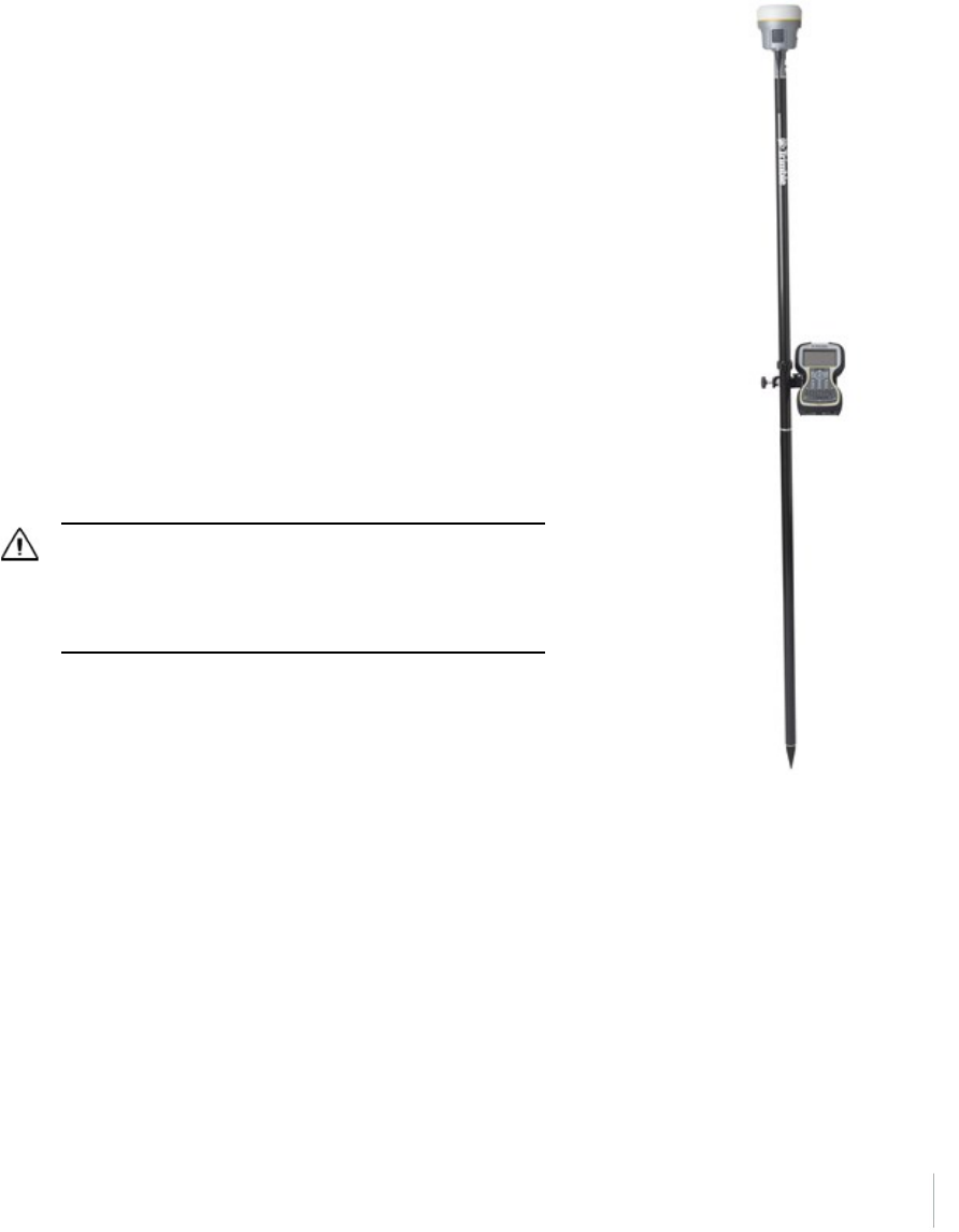
Surepoint (integrated tilt sensor)
The receiver comes with the Surepoint™ technology, which allows the use of full-tilt compensation
and an eBubble (electronic bubble). Surepoint’s full-tilt compensation allows the collection of points
even when the R10 receiver is tilted up to 15 degrees off plumb. When the terrain or structures
around the point do not allow full plumbing of the R10 receiver, the integrated tilt sensor will
compensate for the tilt of the range pole. The point is collected using a point type of compensated
point to initiate the tilt compensation.The eBubble is displayed within the Trimble Access software.
The eBubble is displayed in a separate window for use during any aspect of your survey. To use the
full-tilt compensation and the eBubble correctly, the TSC3 or Trimble Tablet must be aligned
correctly in relationship to the receiver. When the receiver is placed on a range pole, the controller
or tablet must be placed on the right or left side of the receiver with the screen of the controller or
tablet in the same axis as the receiver front panel:
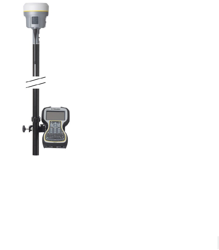
Calibrating the integrated tilt sensor
It is very important to ensure the integrated tilt sensor is correctly calibrated in the same way that
mechanical bubbles are calibrated on your range poles and tribrachs. When calibrating the
integrated tilt sensor you must use a range pole with bi-pod or a tripod with tribrach that have been
well calibrated. The quality of the integrated tilt sensor calibration is directly related to the quality of
the mechanic bubble and its calibration.
Trimble R10 GNSS Receiver User Guide 47
3 Rover Setup and Operation
The integrated tilt sensor calibration is performed within the Trimble Access software. To calibrate
the integrated tilt sensor, place the receiver on a stable range pole or tripod with tribrach. Level the
receiver using the mechanical bubble on the range pole or tribrach. Turn on the receiver and TSC3 or
Trimble Tablet. Run Trimble Access, then:
1. In the General Survey menu:
Tap Instrument.
2. In the Instrument screen:
Tap eBubble options.
3. The eBubble options screen appears.
You are now ready to perform the calibration.
Tap Calib.
Note – An electronic bubble is displayed to indicate if
you are holding the instrument level.
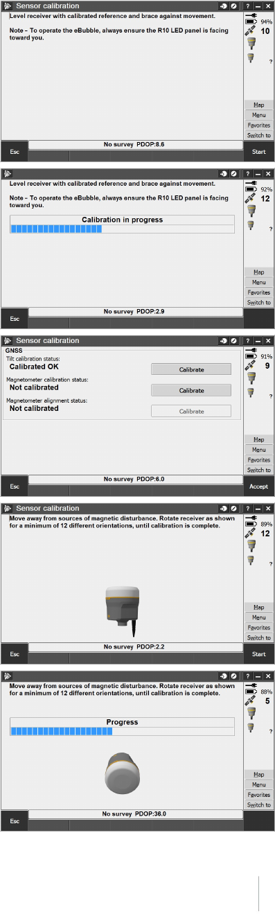
4. The Sensor calibration screen appears.
First the tilt calibration is performed.
Tap the Calibrate button next to the Tilt
calibration status field.
Trimble R10 GNSS Receiver User Guide 48
3 Rover Setup and Operation
5. A message asks you to confirm that the
instrument is level and braced against any
movement.
Tap Start.
6. A progress bar indicates that calibration is in
progress.
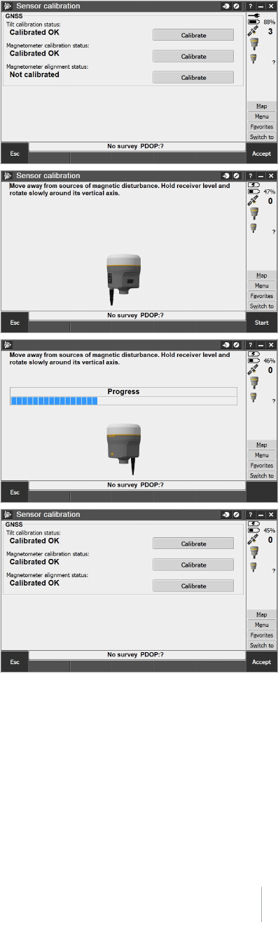
7. Once calibration is complete, the Sensor
calibration screen reappears.
Next you will perform the magnetometer
calibration.
Tap the Calibrate button next to the
Magnetometer calibration status field.
8. A message and graphic is displayed describing the
magnetometer calibration procedure. Observe the
visual graphic of the receiver, and then perform
the calibration as shown.
Tap Start.
9. As you rotate the receiver through the 12
orientations, the progress bar will progress. If the
bar is not progressing or progressing slowly, you
may not be rotating the receiver correctly. Rotate
the receiver in the vertical one complete rotation,
then rotate the receiver in the horizontal a few
degrees. Repeat.
Trimble R10 GNSS Receiver User Guide 49
3 Rover Setup and Operation
10. Once calibration is complete, the Sensor
calibration screen reappears.
Next you will perform the magnetometer
alignment.
Tap the Calibrate button next to the
Magnetometer alignment status field.
11. A message and graphic is displayed describing the
magnetometer alignment procedure. Observe the
visual graphic of the receiver, and then perform
the alignment as shown. Tap Start.
12. As you rotate the receiver 360 degrees in the
horizontal, the progress bar will progress. If the
bar is not progressing or progressing slowly, you
may be rotating the receiver too quickly. Rotate
the receiver at the same speed as the graphic
shows.
13. Once calibration is complete, the Sensor
calibration screen reappears. The full tilt
calibration is complete. Tap Accept to return to
the eBubble options screen.
Trimble R10 GNSS Receiver User Guide 50

3 Rover Setup and Operation
Integrated cellular modem
Instead of the internal radio, you can use the integrated cellular modem as your data
communications link. This will allow you to connect to VRS networks in your area. See your local
Trimble representative for more information on VRS networks.
Using the integrated cellular modem requires a SIM card from your local cellular service provider.
The SIM card is inserted into the SIM card slot in the battery compartment of the receiver. For more
information about setting up your SIM card and cellular service in the receiver, please see your local
Trimble representative.
For more information on using a cellular modem as a data link, refer to the Trimble Access Help.
Trimble R10 GNSS Receiver User Guide 51

3 Rover Setup and Operation
Connecting the receiver to external devices
You can connect the receiver to the following devices:
la Trimble controller running Trimble Access software
lan external radio-modem
Connecting to a Trimble controller running Trimble Access software
You can operate a Trimble R10 GNSS receiver with any Trimble controller, for example, a TSC3 or a
Trimble Tablet. Typically, the receiver and the controller operate from their own individual power
sources. The receiver and controller can communicate through Bluetooth wireless technology and
can be connected without a cable. However, if a cable is required, the following table lists the cables
available for the receiver.
To connect a Trimble R10 GNSS receiver
to a...
Use cable
P/N...
Use cable
connector...
and connect the
cable to the...
computer serial port 89853-00 or
59044
7-pin serial Lemo
DB-9
Receiver
Computer
computer USB port 89852-00 or
80751
7-pin USB Lemo
USB
Receiver
Computer
TSC3 or Trimble Tablet 89851-00 or
59046
DB-9
Serial Lemo
TSC
Receiver
USB flash memory stick 89850-00 or
80799
7-pin USB Lemo
USB flash drive
Receiver
Flash drive
TDL450 66656 7-pin serial Lemo
5-pin Lemo
Receiver
TDL450
Internal radio-modems
The most common data link for Real-Time Kinematic (RTK) operation is a radio. The receiver is
available with the following internal radios:
l410 MHz – 470 MHz (Transmit/Receive)
External radio-modems
If the receiver does not have an internal transmit radio, or you want to connect to a higher powered
external transmit radio or cellular modem, use the Lemo serial port.
The Trimble R10 GNSS receiver supports the following Trimble base radios:
lTrimble TDL450
lTrimble SNB900
Trimble R10 GNSS Receiver User Guide 52

3 Rover Setup and Operation
lLegacy radios such as the Trimble PDL450 radio, Trimble HPB450 radio-modem, and
TRIMMARK™ 3 radio
The receiver also supports third-party transparent radios and third-party cellular modems.
To use an external radio with the receiver, you need an external power source for the radio—except
for the SNB900 radio, which contains an internal battery. To configure the radio modem separately,
use the external radio’s configuration program, or the display and keypad.
Trimble R10 GNSS Receiver User Guide 53

3 Rover Setup and Operation
Configuring the receiver
You can configure the receiver in a number of ways. These topics describe the different
configuration methods, and explain when and why each method is used.
Trimble Access Help is likely to be your main tool to set up and operate the receiver on a daily basis.
All required field configurations are handled through the Trimble Access software running on a
Trimble Tablet, TSC3, or Trimble CU controller. For more information, refer to the Trimble Access
Help.
Configuring the receiver using the Web User Interface (Web UI)
The receiver has a Wi-Fi port so that the receiver can connect directly to a PC or smartphone (access
point mode) or to a wireless network (client mode). You can use Wi-Fi to access, configure, and
monitor the receiver. No cable connection to the receiver is required.
Connecting via Wi-Fi (access point)
The receiver is set to access point by default. In access point mode, the user can connect directly to
the receiver from a PC or smartphone.
1. Using the Wi-Fi connection application on your PC or Smartphone, find the access point SSID
for the receiver. Turn on the Trimble R10 GNSS receiver and wait for the words "Trimble GNSS"
and last four digits of the receiver serial number to appear in your Wi-Fi connection application.
For example, Trimble GNSS xxxx (where xxxx represents the last four digits of the receiver
serial number.
2. Connect to the receiver. By default, all encryption is turned off in the receiver.
3. Open your web browser and then type the receiver IP address into the URL field. By default the
IP address of the receiver is http://192.168.142.1.
4. Enter the login and password for the receiver. By default, the login is admin and the password is
password.
5. The receiver web interface is displayed and the receiver is ready for real-time configuration.
The web page on the smartphone mini-browser opens with a select number of menus. To view
the Full (Classic) menu, use the Show Classic Web GUI link in the heading area. To return to the
mini-browser, the Wi-Fi connection or receiver must be reset (that is, turned on or off).
For more information, search for the topic "Web Interface Menus" in the Trimble R10
Trimble R10 GNSS Receiver User Guide 54
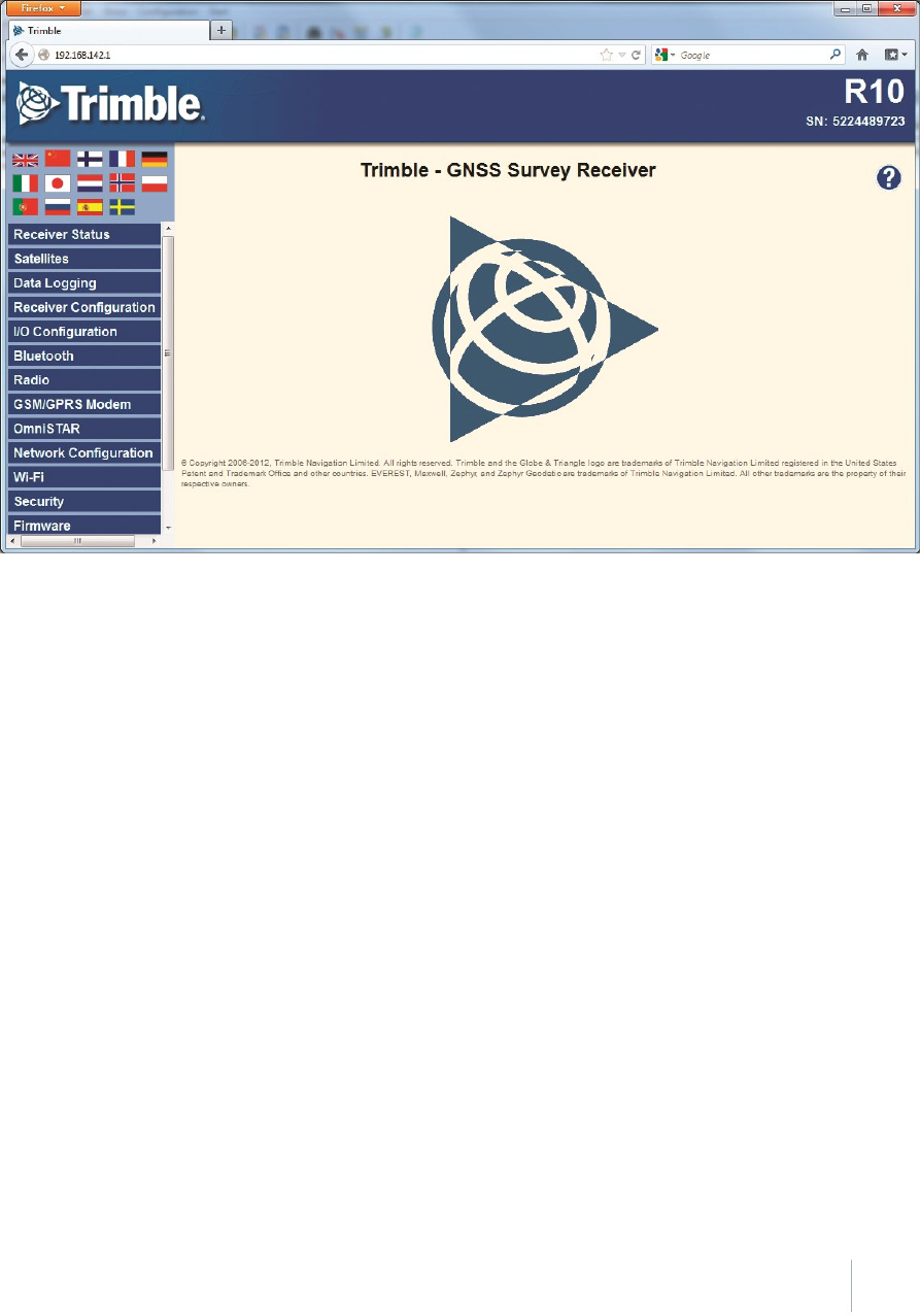
3 Rover Setup and Operation
GNSS Receiver WebHelp.
Default Wi-Fi connection settings
Out of the box, the receiver is configured to default settings for Wi-Fi connections. You can change
any of these settings as required.
The default settings are:
lWi-Fi mode: access point
lWi-Fi SSID: Receiver serial number
lWi-Fi Encryption: Off
lWi-Fi IP Address: 192.168.142.1
lReceiver Login: admin
lReceiver Password: password
Trimble R10 GNSS Receiver User Guide 55

3 Rover Setup and Operation
Web interface menus
Use the web interface to configure the receiver settings
The web interface is available in the following languages:
lEnglish (en)
lChinese (zh)
lDutch (nl)
lFinnish (fi)
lFrench (fr)
lGerman (de)
lItalian (it)
lJapanese (ja)
lNorwegian (n)
lPolish (pl)
lPortuguese (pt)
lRussian (ru)
lSpanish (es)
lSwedish (sv)
Use the Receiver Configuration / Default Language setting to select the default language for your
use.
The web interface shows the configuration menus on the left of the browser window, and the
settings on the right. Each configuration menu contains related submenus to configure the receiver
and monitor receiver performance.
Supported browsers
For PCs and laptops, current versions of these HTML browsers are supported:
lGoogle Chrome
lMozilla Firefox
lMicrosoft Internet Explorer for Windows operating systems
lOpera
lApple Safari
To access the web interface on a Trimble R10 GNSS receiver using a PDA or a smartphone with the
Wi-Fi link to the Trimble R10 GNSS receiver, Trimble recommends:
Trimble R10 GNSS Receiver User Guide 56

3 Rover Setup and Operation
lOpera Mobile for Android-based units
lApple Safari
Menu overview
The following configuration menus are available.
Receiver Status menu
The Receiver Status menu provides a quick link to review the receiver’s available options, current
firmware version, IP address, temperature, runtime, satellites tracked, current outputs, available
memory, position information, and more.
Satellites menu
Use the Satellites menu to view satellite tracking details and enable/disable GPS, GLONASS, and
SBAS satellites.
Note – To configure the receiver for OmniSTAR, use the OmniSTAR menu.
Web Services menu
Use the Web Services menu to plan satellite availability and performance, along with Ionospheric
Maps of your location. All functions are web-based and require an Internet connection.
Data Logging menu
Use the Data Logging menu to set up the receiver to log static GNSS data. You can also configure
settings such as observable rate, position rate, continuous logging, continuous logging rate, and
whether to auto delete old files if memory is low.
Receiver Configuration menu
Use the Receiver Configuration menu to configure such settings as elevation mask and PDOP mask,
and the reference station position, and the reference station name and code.
I/O Configuration menu
Use the I/O Configuration menu to set up all outputs of the receiver. Depending on the receiver's
specification it may output CMR, RTCM, RTCM-REPEAT, RT17/RT27, NMEA, or GSOF messages on a
variety of ports including TCP/IP, NTRIP, UDP, serial, or Bluetooth ports.
Bluetooth menu
Use the Bluetooth menu to configure the receiver to connect to other devices that use Bluetooth
wireless technology. These devices can be used to configure the receiver, and generate or receive
corrections.
The following Trimble devices can be connected to the receiver using Bluetooth wireless technology:
Trimble R10 GNSS Receiver User Guide 57

3 Rover Setup and Operation
lTSC3 controller
lTrimble Tablet
lTrimble Slate controller
lOther Bluetooth-enabled devices
Radio menu
The Trimble R10 receiver can include an internal radio. Either UHF or VHF models are available for
purchase.
Use the Radio menu to configure the internal UHF radio of the receiver, if applicable. The receivers
are available with 410 MHz to 430 MHz radios.
Use the Radio menu to configure the internal VHF radio of the receiver.
If the receiver does not have an internal radio installed, the Radio menu is not available.
GSM/GPRS modem menu
Use the GSM/GPRS modem menu to check the status and configure the internal UMTS modem. It
includes information about the inserted SIM card.
OmniSTAR menu
The receiver can receive OmniSTAR corrections.
To receive CenterPoint RTX corrections, you must enable the receiver to track the RTX satellites and
it must have a valid CenterPoint RTX subscription.
To obtain a subscription or contact support, go to www.omnistar.com/servicemap.html.
To obtain a CenterPoint RTX subscription or contact support, go to
http://www.trimble.com/positioning-services/order-now.aspx.
Network Configuration menu
Use the Network Configuration menu to configure Ethernet settings, email alerts, PPP connection,
HTTP port, and FTP port settings of the receiver.
Wi-Fi
Use the Wi-Fi menu to configure the Wi-Fi access mode and access point, so that using a Wi-Fi
enabled device such as a smartphone, you can access the web interface of a Trimble R10 GNSS
receiver.
Security menu
Use the Security menu to configure the login accounts for all users who will be permitted to
configure the receiver using a web browser. Each account consists of a username, password, and
permissions. Administrators can use this feature to limit access to other users. Security can be
Trimble R10 GNSS Receiver User Guide 58

3 Rover Setup and Operation
disabled for a receiver. However, Trimble discourages this as it makes the receiver susceptible to
unauthorized configuration changes.
Firmware menu
Use the Firmware menu to verify the current firmware and load new firmware to the receiver. You
can upgrade firmware across a network or from a remote location without having to connect to the
receiver with a serial cable.
Help menu
To access the Help, your computer must be connected to the Internet. If you do not have access to
the Internet, there is also a copy of the receiver Help files on the support area of the Trimble website
(www.trimble.com/support.shtml).
Configuring the receiver in real time
You can configure the receiver in real time using the web interface on your PC via Wi-Fi, Bluetooth
(PPP), USB (PPP) or Serial (PPP). A new feature available on the Trimble R10 GNSS receiver is the
mini-browser, easily accessed using a smartphone with Wi-Fi. The new mini-browser makes a select
group of Web GUI menus available, with the option of showing the full set of Web GUI menus.
When you apply the changes you have made to the settings in the web interface, the receiver
settings change immediately.
Note – Instructions for connecting to the Trimble R10 GNSS receiver via PPP (Point-to-Point
Protocol) are found on the Trimble web site under the Trimble R10 GNSS receiver support notes.
Any changes that you apply to the receiver are reflected in the current application file, which is
always present in the receiver.
Trimble R10 GNSS Receiver User Guide 59

3 Rover Setup and Operation
Configuring the receiver using application files
An application file contains information for configuring a receiver. To configure a receiver using an
application file, you need to create the application file, transfer it to the receiver and then apply the
file’s settings. The GPS Configurator software does this automatically when you work with
configuration files.
Overview
An application file is organized into records. Each record stores configuration information for a
particular area of receiver operation. Application files can include the following records:
lFile storage
lGeneral controls
lSerial port baud rate/format
lReference position
lLogging rate
lSV enable/disable
lOutput message
lAntenna
lDevice control
lStatic/Kinematic
An application file does not have to contain all of these records. When you apply an application file,
any option that is not included in the records in the file remains at its current setting. For example, if
you apply an application file that only specifies the elevation mask to use, all other settings remain
as they were before the application file was applied.
You can store up to 11 different application files in the receiver. You can apply an application file’s
settings at the time it is transferred to the receiver, or at any time afterwards.
Special application files
The receiver has three special application files, which control important aspects of the receiver’s
configuration.
Default application file
The default application file (Default.cfg) contains the original receiver configuration, and cannot be
changed. This file configures the receiver after it is reset.
To reset the receiver, see Button and LED operations, page 26
Trimble R10 GNSS Receiver User Guide 60

3 Rover Setup and Operation
Although you cannot change or delete the default application file, you can use a power up
application file to override any or all of the default settings.
Current application file
The current application file (Current.cfg) reflects the current receiver configuration. When you
change the receiver’s configuration, either in real time or by applying an application file, the current
file changes to match the new configuration.
You cannot delete the current file or change it directly, but every change to the receiver’s current
configuration is applied to the current file as well.
When you switch off the receiver and then turn it on again, all the settings from the current
application file are applied, so you do not lose any changes that you have made. The only
exceptions are the following logging parameters:
lLogging rate
lPosition rate
lElevation mask
These parameters are always reset to the factory default values when the receiver is switched off.
Power Up application file
The power up application file (Power_up.cfg) is used to set the receiver to a specific configuration
any time the unit is powered up.
In this file, you can specify that the receiver is reset to defaults before the power up settings are
applied. This ensures that restarting the receiver always resets it to factory defaults before applying
the power up application file.
Alternatively, you can specify that the power up settings are applied immediately after the current
application file’s settings have been applied. Restarting the receiver results in a configuration that
uses your default settings for the options you define in the power up file, but the current settings
for all other options.
By default, there is no power_up application file on the receiver. To use a power up application file,
you must create and save a power_up application file in the GPS Configurator software. If you save
this file to disk, the file is called power_up.cfg. The extension .cfg is used, by convention, to identify
application files on the office computer. When you transfer this file to the receiver, the file is saved
on the receiver as power_up, and becomes the new power up file.
Applying application files
An application file’s settings do not affect the receiver’s configuration until you apply the
application file. You can do this at the same time that you save the file. Alternatively, you can save
the file on the computer or on the receiver, then open it later and apply its settings.
Trimble R10 GNSS Receiver User Guide 61

3 Rover Setup and Operation
Storing application files
You can store application files that you create in the GPS Configurator software on the receiver and
on the computer. For example, each file can represent a different user sharing the same receiver, or
a particular mode of operation. Saving application files on your computer as well as in your receiver
is optional, but it is useful because:
lit gives you a permanent copy of the settings you have sent to a receiver, for audit purposes or
for your own reference.
lyou can use the same file to configure multiple receivers identically.
lyou can use an existing application file as a template to create other application files with similar
settings.
Naming application files
The application filename in the office computer and in the receiver are always the same. This makes
it easier to recognize and keep track of your application files.
When you change the name of the application file in the receiver, this changes the application
filename on your computer. When you transfer an application file from the receiver and save it to
the computer, the system renames the file to match the internal receiver file. However, if you use
Windows Explorer, for example, to change the .cfg filename on the computer, this does not change
the internal receiver filename. This means that the GNSS receiver will not recognize the change to
the filename on the computer.
Trimble R10 GNSS Receiver User Guide 62

3 Rover Setup and Operation
Configuring the receiver to use specific settings when it is turned
on
The power up application file (Power_up.cfg) is used to set the receiver to a specific configuration
any time the unit is turned on.
In this file, you can select to reset the receiver to defaults before the power up settings are applied.
This ensures that when you restart the receiver, it always resets to factory defaults before applying
the power up application file.
Alternatively, you can specify that the power up settings are applied immediately after the current
application file’s settings have been applied. Restarting the receiver results in a configuration that
uses your default settings for the options you define in the power up file, but the current settings
for all other options.
By default, there is no power_up application file on the receiver. To use a power up application file,
you must create and save a power_up application file in the GPS Configurator software. If you save
this file to disk, the file is called power_up.cfg. The extension .cfg is used, by convention, to identify
application files on the office computer. When you transfer this file to the receiver, the file is saved
on the receiver as power_up, and becomes the new power up file.
Transferring files directly from the receiver
Data is stored in the internal flash memory. To transfer files between the receiver and an office
computer, use one of the following methods.
lLemo (Port 1) to traditional serial port and the Trimble Business Center.
lLemo (Port 2) to USB PC connection (Trimble R10 GNSS receiver appears as a Trimble data
external drive).
lLemo (Port 2) to USB field data cable (transfer to USB flash memory stick and then plug flash
memory stick into PC).
lConnect via Wi-Fi to the receiver's Web UI, then use the Datalogging menu to navigate to the
receiver's file directory. Select the files to download to a directory on your PC, and the file
format you want to download the data in (for example, RINEX).
Deleting files in the receiver
You can delete files stored in the receiver at any time. Do one of the following:
lPress for 30 seconds after the receiver is turned on. (When you use this method, all data is
deleted.)
lUse the web interface (Data Logging menu).
Trimble R10 GNSS Receiver User Guide 63

4 The WinFlash Utility
In this chapter:
nThe WinFlash utility
nUpgrading the receiver firmware
nAdding frequencies for the 450 MHz internal
radio using the WinFlash utility
nConfiguring the internal transceiver
nConfiguring a PC USB port as a virtual serial
port
Trimble R10 GNSS Receiver User Guide 64
4
CHAPTER

4 The WinFlash Utility
The WinFlash utility
The WinFlash utility communicates with Trimble products to perform various functions including:
linstalling software, firmware, and option upgrades
lrunning diagnostics (for example, retrieving configuration information)
lconfiguring radios
Note – The WinFlash utility runs on Windows 2000, XP, Windows Vista®, and Windows 7 operating
systems.
Installing the WinFlash utility
You can download and install the WinFlash utility from the Trimble website by downloading the
latest receiver firmware. The latest firmware is available in the Support area under R10 Downloads.
Note – If your computer or laptop only has USB ports, then you must set up a virtual serial port.
See Configuring a PC USB port as a virtual serial port, page 70.
To install the WinFlash utility from the web:
1. Click the link for the latest firmware.
2. When prompted, select Run to install WinFlash.
The Winflash Installation Setup application appears.
3. Follow the on-screen instructions.
Note – The WinFlash utility guides you through the firmware upgrade process. For more
information, refer to the WinFlash Help.
Upgrading the receiver firmware
Your receiver is supplied with the latest version of the receiver firmware already installed. If a later
version of the firmware becomes available, you can use the WinFlash utility to upgrade the firmware
on your receiver as long as your receiver has a current warranty.
You can use Wi-Fi to upgrade the firmware for your receiver using the web browser. Whenever
Trimble releases new firmware your receiver will check and display the new firmware version
number in the Web browser. You can then decide to install the newer firmware from the Web
browser.
Firmware updates are available to download from the Trimble website. Go to
agpartners.trimble.com.
Trimble R10 GNSS Receiver User Guide 65

4 The WinFlash Utility
To upgrade the firmware using WinFlash
1. Start the WinFlash utility. The Device Configuration screen appears.
2. From the Device type list, select the receiver.
3. From the PC serial port field, select the serial (COM) or USB port on the computer that the
receiver is connected to.
4. Click Next.
The Operation Selection screen appears. The Operations list shows all of the supported
operations for the selected device. A description of the selected operation is shown in the
Description field.
5. Select Load GPS software and then click Next.
The GPS Software Selection window appears. This screen prompts you to select the software
that you want to install on the receiver.
6. From the Available Software list, select the latest version and then click Next.
The Settings Review window appears. This screen prompts you to connect the receiver,
suggests a connection method and then lists the receiver configuration and selected operation.
7. If all is correct, click Finish.
Based on your selections, the Software Upgrade window appears and shows the status of the
operation, for example, Establishing communication with <your receiver>. Please wait.
8. Click OK.
The Software Upgrade window appears again with a message that the operation was
completed successfully.
9. To select another operation, click Menu; to quit the WinFlash utility, click Exit.
If you click Exit, the system prompts you to confirm.
10. Click OK.
Trimble R10 GNSS Receiver User Guide 66

4 The WinFlash Utility
Adding frequencies for the 450 MHz internal radio using the WinFlash
utility
If your receiver has the optional internal radio installed, you can use the WinFlash utility to add
receiving frequencies to the default list.
You can also use the web interface to add and manage receiver 450 MHz frequencies.
If you purchase a transmit upgrade (after initial purchase), the broadcast frequencies must be
programmed using a .set file obtained from a Trimble service provider.
1. Start the WinFlash utility. The Device Configuration screen appears.
2. From the Device type list, select the receiver.
3. From the PC serial port field, select the serial (COM) port or USB port on the computer that the
receiver is connected to.
4. Click Next.
The Operation Selection screen appears. The Operations list shows all of the supported
operations for the selected device. A description of the selected operation is shown in the
Description field.
5. Select Configure Radio and then click Next.
The Frequency Selection dialog appears.
6. In the Wireless Format group, select the appropriate channel and wireless mode. The wireless
mode must be the same for all radios in your network.
7. In the Specify Frequency field, enter the frequency you require.
8. Click Add. The new frequency appears in the Selected Frequencies list.
Note – The frequencies that you program must conform to the channel spacing and minimum
tuning requirements for the radio. To view this information, click Radio Info. You may select
either 12.5 or 25 kHz channel spacing. All radios in your network must use the same channel
spacing.
9. When you have configured all the frequencies you require, click OK.
The WinFlash utility updates the receiver radio frequencies and then restarts the receiver.
Note – You can only configure receive frequencies. The FCC-approved transmit frequencies
must be specified and configured by Trimble.
Trimble R10 GNSS Receiver User Guide 67
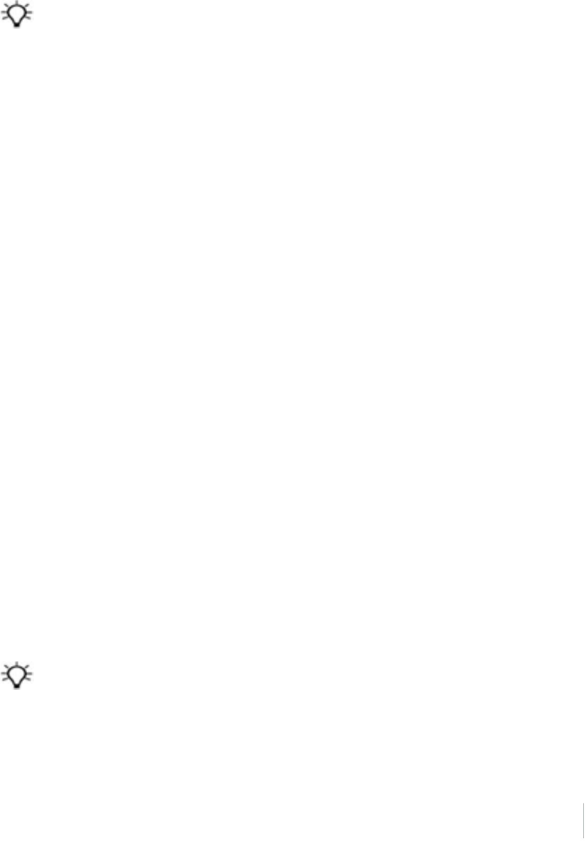
4 The WinFlash Utility
Configuring the internal transceiver
Use the WinFlash utility Internal Transceiver Configuration dialog to configure the internal
transceiver.
Tip – To view a list of all radio information, including the current configuration, click Radio Info.
1. In the Internal Transceiver Configuration dialog, select the current channel. This
determines the radio operating frequency.
2. Select the wireless mode, which determines the over-the-air communications parameters.
To reduce battery consumption on your base receiver, set the wireless mode as high as
possible. For example, 9600 bps (bits per second) consumes half the power of 4800 bps for the
same data format and time of operation.
Note – All radios in the network must be configured with the same wireless setting.
3. Select the appropriate operating mode, depending on how you intend to use the receiver. For
example, select "Base with No Repeaters".
4. For base modes only, select one of the following channel-sharing configurations: (this is not
available for rover modes)
l lOff. The carrier detect mode is off. The unit will ignore other transmissions on your
frequency and continue to transmit data.
Note – It may be illegal in your country of use to set channel sharing to off. You may be
subject to penalties or fines based upon the specific licensing requirements of your
country of use. Please consult your radio license documentation or licensing agency for
operational guidelines.
lAvoid Weak Signals. The carrier detect mode is on. The radio will cease transmitting if it
detects another radio transmission on its frequency. It will resume transmission when the
channel is free of radio traffic.
lAvoid Strong Signals. The carrier detect mode is on, but the radio will stop transmitting
only when there is a strong signal present (receive level greater than 90 dBm).
5. If you are operating in base mode, select the Enable Station ID check box and then enter your
call sign in the Call Sign field. This FCC requirement is for U.S. licensed users. It sets your radio
to transmit your call sign in Morse code every 15 minutes.
6. To update the configuration, click OK.
In the Status dialog that appears, select an option to return to the main menu or to exit the
WinFlash utility.
Tip – You can print or save the radio configuration information for future reference. If required, you can fax or
email the file to Trimble Support to aid in troubleshooting radio issues.
Trimble R10 GNSS Receiver User Guide 68

4 The WinFlash Utility
Updating the frequency list
You can program the internal transceiver modem with a list of up to 20 frequencies, which are
stored in non-volatile memory. This list is pre-configured based on the frequencies that you
requested when you ordered the unit. Government regulations stipulate that only manufacturers
or authorized dealers can create this frequency list and that all frequencies programmed into a unit
must comply with the host country regulations. If you need to add, delete, or replace frequencies,
contact your Trimble dealer, and provide the radio modem serial number and an updated list of the
frequencies you require. Once you receive the frequency file, you can upgrade the radio using the
WinFlash utility.
Trimble R10 GNSS Receiver User Guide 69

4 The WinFlash Utility
Configuring a PC USB port as a virtual serial port
It is possible to use the USB interface from a Trimble R10 GNSS receiver with a software application
that requires a serial port.
For example, the Trimble WinFlash utility can be run on a computer that has no physical serial port
by connecting the USB cable between the computer and the receiver.
Windows 7 Professional operating system
1. The simplest way to install the virtual serial port for the USB interface to the receiver is to go to
the Trimble Support website (www.trimble.com/support) and search for the Trimble R10 GNSS
receiver. In the Downloads section, download the file called Windows7 USB Installer to your
computer.
This file contains a Support Note and installation program.
2. Run the installation program. It will load the virtual serial port for the USB interface on your
computer.
Note – If you have installed the Trimble WinFlash utility (www.trimble.com/support) on your
computer, then another way to install the virtual serial port for the USB interface is to run the
USB Installer program, which is located in C:\Program Files\Common Files\Trimble\USBDriver.
If this process does not work for your computer, or if you have a different Windows operating
system on your computer, then follow the procedure below.
Windows Vista and Windows 7 operating system
1. Go to the Trimble Support website (www.trimble.com/support) and search for the receiver you
have. In the Support Notes section, download the file called R10 GNSS Interface to a Virtual
COM port on a Computer to your computer.
2. Open the file and place the trmbUsb.inf file in a temporary folder on your computer.
3. On the computer, select Control Panel / Device Manager.
4. Click on the name of the computer and then from the Action menu, select Add Legacy Driver.
5. A wizard prompts you to locate the TrimbleUsb.inf file. Locate the file and then follow the
prompts in the wizard to continue.
Windows XP operating system
1. Go to the Trimble Support website (www.trimble.com/support) and search for the Trimble R10
GNSS receiver. In the Support Notes section, download the file called R10 GNSS Interface to a
Virtual COM port on a Computer to your computer.
2. Open the file and place the trimble.Usb.INF file in a temporary folder on your computer.
3. Turn on the receiver and then connect the USB cable to the computer. The New Hardware
Trimble R10 GNSS Receiver User Guide 70

4 The WinFlash Utility
wizard appears.
4. Select the No, not this time option and then click Next.
5. A dialog prompts you to specify the location of the USBSer.sys file. For example,
C:\Windows\System32\Drivers.
6. On some computers you may need to repeat Step 4 for the TrimbleUsb.inf file.
7. Check that the receiver is available for use. Go to the Device Manager menu on the computer.
The receiver should appear in the Ports list.
Note – If you are running an application such as WinFlash software on the computer and you
physically disconnect the USB cable from the computer and then reconnect it, it does not always
re-establish the connection. This is because opening the serial port from the application locks the
device handle and when the USB device is disconnected, the application does not close the serial
port and the device handle is still locked. On reconnecting, the USB cable is unable to get the device
handle since it is locked. You must close the application before the reconnect to the port will work.
This limitation is due to the behavior of the Microsoft USB serial driver.
Trimble R10 GNSS Receiver User Guide 71

5 Troubleshooting
Troubleshooting receiver issues
This section describes some possible receiver issues, possible causes, and how to solve them. Please
read this section before you contact Technical Support.
The receiver does not turn on
Possible cause Solution
External power is too
low.
Check the charge on the external power supply, and check the fuse if
applicable. If required, replace the battery.
Internal power is too
low.
Do the following:
lCheck the charge on the internal batteries and replace if required.
lEnsure battery contacts are clean.
External power is not
properly connected.
Do the following:
lCheck that the Lemo connection is seated properly.
lCheck for broken or bent pins in the connector.
Faulty external
power cable.
Do the following:
lTry a different cable.
lCheck pinouts with multimeter to ensure internal wiring is intact.
The receiver is not tracking any satellites
Possible cause Solution
The GNSS antenna does not have clear
line of sight to the sky.
Ensure that the antenna has a clear line of sight.
The receiver does not log data
Possible cause Solution
Insufficient memory in the
internal memory.
Delete old files. Press the Power button for 30 seconds.
The receiver is not responding
Possible cause Solution
The receiver needs
a soft reset.
Turn off the receiver and then turn it back on again. For more information, see
Button and LED operations, page 26
Trimble R10 GNSS Receiver User Guide 73
5 Troubleshooting
Possible cause Solution
The receiver needs
a full reset.
Press the Power button for 30 seconds. For more information, see Button and
LED operations, page 26.
Troubleshooting LED conditions
The receiver has a simple display panel with LEDs to indicate the current status of the receiver. If you
need more detailed information about what the receiver is doing, use a Trimble controller or access
all configuration settings by connecting the receiver to your smart phone or laptop computer via
Configuring the receiver using the Web User Interface (Web UI), page 54.
This section describes how the LED lights are used on the receiver to indicate current status. An LED
that is flashing quickly indicates a condition that may require attention, and an unlit LED indicates
that no operation is occurring. This section describes some LED conditions, possible causes, and
how to solve them.
The SV Tracking LED is lit solidly and the Logging/Memory LED is flashing
slowly
Possible cause Solution
The receiver is in
Monitor mode, ready
for new firmware to be
loaded or new options
to be added.
Turn on or turn off the receiver. If that does not fix the problem, load the
latest version of the firmware, which you can download from the Trimble
website (www.trimble.com/support.shtml / <product> / Downloads).
The SV Tracking LED is not flashing
Possible cause Solution
The receiver is tracking fewer than
four satellites.
Wait until the SV Tracking LED is flashing slowly.
Trimble R10 GNSS Receiver User Guide 74
5 Troubleshooting
Troubleshooting base station setup and static
measurement problems
This section describes some possible station setup and static measurement issues, possible causes,
and how to solve them.
Trimble recommends that you use the Trimble Access software to restart or configure base and
rover receivers. The Trimble Access software sets up all radio and receiver operating parameters,
and is the most likely route to a successful problem resolution once you have checked all
connections, cables, and batteries.
The roving receiver is not receiving radio from the base station
Possible cause Solution
The base station is not
broadcasting.
See "Base station is not broadcasting" below.
Incorrect over air baud rates
between base station and
rover.
Connect to the roving receiver's radio and make sure that it has
the same setting as the base station receiver.
Mismatched channel or
network number selection.
Match the base station and rover radio channels/network number
and try again.
Incorrect port settings between
the rover external radio and
receiver.
If the radio is receiving data (the Radio LED is flashing) and the
receiver is not receiving data, check the port settings of the
receiver and radio using the Trimble Access software; match the
settings and try again.
The base station is not broadcasting
Possible cause Solution
Port settings between base receiver and
external radio are incorrect.
Note – The Trimble R10 GNSS receiver has
the option for an integrated Tx radio that
allows it to be used without an external radio
at the base and rover location. The receiver
can also be connected to an external high
power radio in certain countries.
Use Trimble Access software to connect to the radio
through the receiver. If no connection is made, connect
directly to the radio and change the port settings. Try to
connect through the receiver again to ensure that they
are communicating.
Note – Trimble Access software does not support direct
connection to the external radio; it only allows configuration
through the receiver.
Faulty cable between receiver and
external radio.
Do one of the following:
lTry a different cable
lExamine the ports for missing pins
lUse a multimeter to check the pins
Trimble R10 GNSS Receiver User Guide 75

6 Output Messages
In this chapter:
nNMEA-0183 messages: Overview
nNMEA-0183 messages: Common message
elements
nGSOF Messages: Overview
nGSOF messages: General Serial Output
Format
nGSOF messages: Reading binary values
(Motorola format)
nLogin authentication
Trimble R10 GNSS Receiver User Guide 76
6
CHAPTER

6 Output Messages
NMEA-0183 messages: Overview
When NMEA-0183 output is enabled, a subset of NMEA-0183 messages can be output to external
instruments and equipment connected to the receiver serial ports. These NMEA-0183 messages let
external devices use selected data collected or computed by the GNSS receiver.
All messages conform to the NMEA-0183 version 3.01 format. All begin with $ and end with a
carriage return and a line feed. Data fields follow comma (,) delimiters and are variable in length. Null
fields still follow comma (,) delimiters, but contain no information.
An asterisk (*) delimiter and checksum value follow the last field of data contained in an NMEA-0183
message. The checksum is the 8-bit exclusive of all characters in the message, including the commas
between fields, but not including the $ and asterisk delimiters. The hexadecimal result is converted
to two ASCII characters (0–9, A–F). The most significant character appears first.
The following table summarizes the set of NMEA messages supported by the receiver, and shows
the page that contains detailed information about each message.
Message Function
DTM Datum reference information
GBS GNSS satellite fault detection (RAIM support)
GGA Time, position, and fix related data
GLL Position data: position fix, time of position fix, and status
GNS GNS Fix data
GRS GRS range residuals
GSA GPS DOP and active satellites
GST Position error statistics
GSV Number of SVs in view, PRN, elevation, azimuth, and SNR
HDT Heading from True North
LLQ Leica local position and quality
PFUGDP A proprietary message containing information about the type of positioning system,
position, number of satellites and position statistics
PTNL,AVR Time, yaw, tilt, range, mode, PDOP, and number of SVs for Moving Baseline RTK
PTNL,BPQ Base station position and position quality indicator
PTNL,DG L-band corrections and beacon signal strength and related information
PTNL,GGK Time, position, position type, and DOP values
PTNL,PJK Time, position, position type, and DOP values
PTNL,PJT Projection type
PTNL,VGK Time, locator vector, type, and DOP values
PTNL,VHD Heading Information
RMC Position, Velocity, and Time
ROT Rate of turn
VTG Actual track made good and speed over ground
ZDA UTC day, month, and year, and local time zone offset
Trimble R10 GNSS Receiver User Guide 77

6 Output Messages
To enable or disable the output of individual NMEA messages, do one of the following:
lCreate an application file in the Configuration Toolbox software that contains NMEA output
settings and then send the file to the receiver.
lAdd NMEA outputs in the Serial outputs tab of the GPS Configurator software and then apply
the settings.
For a copy of the NMEA-0183 Standard, go to the National Marine Electronics Association website at
www.nmea.org.
Trimble R10 GNSS Receiver User Guide 78

6 Output Messages
NMEA-0183 messages: Common message elements
Each message contains:
la message ID consisting of $GP followed by the message type. For example, the message ID of
the GGA message is $GPGGA.
la comma.
la number of fields, depending on the message type, separated by commas.
lan asterisk.
la checksum value.
The following example shows a simple message with a message ID ($GPGGA), followed by 13 fields
and a checksum value:
$GPGGA,172814.0,3723.46587704,N,12202.26957864,W,2,6,1.2,18.893,M,-25.669,M,2.0,0031*4F
Message values
NMEA messages that the receiver generates contains the following values:
Value Description
Latitude and
Longitude
Latitude is represented as ddmm.mmmm and longitude is represented as
dddmm.mmmm, where:
ldd or ddd is degrees
lmm.mmmm is minutes and decimal fractions of minutes
Direction Direction (north, south, east, or west) is represented by a single character: N , S
, E , or W.
Time Time values are presented in Universal Time Coordinated (UTC) and are
represented as hhmmss.ss, where:
lhh is hours, from 00 through 23
lmm is minutes
lss.ss is seconds with variable length decimal-fraction of seconds
Trimble R10 GNSS Receiver User Guide 79

6 Output Messages
GSOF Messages: Overview
These topics provides information on the General Serial Output Format (GSOF) messages. GSOF
messages are a Trimble proprietary format and can be used to send information such as position
and status to a third-party device.
This table summarizes the GSOF messages that the receiver supports. When GSOF output is
enabled, the following messages can be generated:
Message Function
Attitude Info Attitude info
Base Position and Quality Base station position and its quality
Battery/Memory Info Receiver battery and memory status
Brief SV Info GPS SV Brief info
Current Time UTC Current UTC time
Delta ECEF Earth-Centered, Earth-Fixed Delta position
Detail SV Info GPS SV Detailed info
DOP Info PDOP info
Lat, Long, Ht Latitude, longitude, height
Local ENU Local zone north, east, and height - projection/calibration based
Local LLH Local datum position
Position Sigma Position sigma info
Position Time Position time
TPlane ENU Tangent Plane Delta
Velocity Velocity data
ECEF Position ECEF Position
Multiple Page Detail All SV Multiple Page All SV Detailed Info
For information on how to output GSOF messages, see Configuring the receiver, page 54.
Trimble R10 GNSS Receiver User Guide 80

6 Output Messages
GSOF messages: General Serial Output Format
Report packet 40h structure (GENOUT)
Byte Item Type Value Meaning
0 STX Char 02h Start transmission
1 STATUS Char
See
Receiver
status
code
Receiver status code
2 PACKET TYPE Char
40h
Report Packet 40h (GENOUT)
3 LENGTH Char
00h–FAh
Data byte count
4 TRANSMISSION
NUMBER
Char
Unique number assigned to a group of record
packet pages. Prevents page mismatches when
multiple sets of record packets exist in output
stream.
5 PAGE INDEX Char 00h–FFh
Index of current packet page.
6 MAX PAGE
INDEX Char 00h–FFh
Maximum index of last packet in one group of
records.
One or more GSOF messages
Output record
type
Char 01h For example, Time (Type 1 Record)
Record length Char 0Ah Bytes in record
Various fields depending on Output record type.
There can be various records in one GENOUT packet. There could be multiple GENOUT packets per
epoch. Records may be split over two consecutive packets.
Length +
4
CHECKSUM – – (Status + type + length + data bytes) modulo 256
Length +
5
ETX 03h End transmission
Each message begins with a 4-byte header, followed by the bytes of data in each packet. The packet
ends with a 2-byte trailer. Byte 3 is set to 0 (00h) when the packet contains no data. Most data is
transmitted between the receiver and remote device in binary format.
Trimble R10 GNSS Receiver User Guide 81

6 Output Messages
Receiver Status code
Byte
number
Description
Bit 0 Reserved
Bit 1 If set, low battery at the base station
Bit 2 Reserved
Bit 3 If set, receiver's kinematic state is currently set to 'Roving', otherwise 'static'
Bit 4–7 Reserved
Trimble R10 GNSS Receiver User Guide 82

6 Output Messages
GSOF messages: Reading binary values (Motorola format)
The receivers store numbers in Motorola format. The byte order of these numbers is the opposite
of what personal computers (Intel format) expect. To supply or interpret binary numbers (8-byte
DOUBLES, 4-byte LONGS, and 2-byte INTEGERS), the byte order of these values must be reversed.
This section contains a detailed description of the Motorola format.
INTEGER data types
The INTEGER data types (CHAR, SHORT, and LONG) can be signed or unsigned. By default, they are
unsigned. All integer data types use two’s complement representation. The following table lists the
integer data types:
Type # of bits Range of values (Signed) Unsigned
Char 8 -128 to 127 0 to 255
Short 16 -32768 to 32767 0 to 65535
Long 32 –2147483648 to 2147483647 0 to 4294967295
FLOATING-POINT data types
Floating-point data types are stored in the IEEE SINGLE and DOUBLE precision formats. Both formats
have a sign bit field, an exponent field, and a fraction field. The fields represent floating-point
numbers in the following manner:
Floating-Point Number = <sign> 1.<fraction field> x 2(<exponent field> - bias)
Sign bit field
The sign bit field is the most significant bit of the floating-point number. The sign bit is 0 for positive
numbers and 1 for negative numbers.
Fraction field
The fraction field contains the fractional part of a normalized number. Normalized numbers are
greater than or equal to 1 and less than 2. Since all normalized numbers are of the form
1.XXXXXXXX, the 1 becomes implicit and is not stored in memory. The bits in the fraction field are
the bits to the right of the binary point, and they represent negative powers of 2.
For example:
0.011 (binary) = 2-2 + 2-3 = 0.25 + 0.125 = 0.375
Exponent field
The exponent field contains a biased exponent; that is, a constant bias is subtracted from the
number in the exponent field to yield the actual exponent. (The bias makes negative exponents
possible.)
Trimble R10 GNSS Receiver User Guide 83
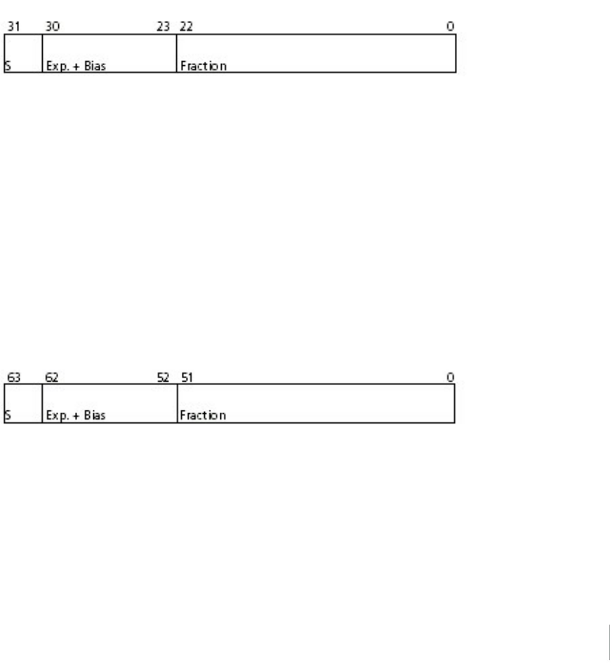
6 Output Messages
If both the exponent field and the fraction field are zero, the floating-point number is zero.
NaN
A NaN (Not a Number) is a special value that is used when the result of an operation is undefined.
For example, adding positive infinity to negative infinity results in a NaN.
FLOAT data type
The FLOAT data type is stored in the IEEE single-precision format which is 32 bits long. The most
significant bit is the sign bit, the next 8 most significant bits are the exponent field, and the
remaining 23 bits are the fraction field. The bias of the exponent is 127. The range of single-precision
format values is from 1.18 x 10–38 to 3.4 x 1038. The floating-point number is precise to 6 decimal
digits.
0 000 0000 0 000 0000 0000 0000 0000 0000 = 0.0
0 011 1111 1 000 0000 0000 0000 0000 0000 = 1.0
1 011 1111 1 011 0000 0000 0000 0000 0000 = -1.375
1 111 1111 1 111 1111 1111 1111 1111 1111 = NaN
DOUBLE
The DOUBLE data type is stored in the IEEE double-precision format which is 64 bits long. The most
significant bit is the sign bit, the next 11 most significant bits are the exponent field, and the
remaining 52 bits are the fractional field. The bias of the exponent is 1023. The range of single
precision format values is from 2.23 × 10–308 to 1.8 × 10308. The floating-point number is precise to
15 decimal digits.
0 000 0000 0000 0000 0000 ... 0000 0000 0000 = 0.0
0 011 1111 1111 0000 0000 ... 0000 0000 0000 = 1.0
1 011 1111 1110 0110 0000 ... 0000 0000 0000 = -0.6875
1 111 1111 1111 1111 1111 ... 1111 1111 1111 = NaN
Trimble R10 GNSS Receiver User Guide 84

6 Output Messages
Login authentication
If you interface to the receivers using binary commands over serial communications, you may need
login authentication. This is added to receiver models that run firmware version 3.30 or later.
If utilities such as the WinFlash utility or the Configuration ToolBox software do not work with the
receivers running firmware version 3.30 or later, go to the Trimble website and then download the
latest versions of these utilities. If your own application software no longer communicates with the
receiver, contact Trimble Support for information about how to use the receiver in these cases.
Trimble R10 GNSS Receiver User Guide 85

7 Specifications
Specifications
Measurements
lAdvanced Trimble Maxwell™ 6 Custom Survey GNSS chips with 440 channels
lSatellite signals tracked simultaneously:
l lGPS: L1C/A, L1C, L2C, L2E, L5
lGLONASS: L1C/A, L1P, L2C/A, L2P, L3
lSBAS: L1C/A, L5 (For SBAS satellites that support L5)
lGalileo: E1, E5a, E5B
lBeidou: B1, B2
lOmniSTAR HP, XP, G2, VBS positioning
lTrimble CenterPoint RTX
lQZSS, WAAS, MSAS, EGNOS, GAGAN
lVery low noise GNSS carrier phase measurements with <1 mm precision in a 1 Hz bandwidth
lSignal-to-noise ratios reported in dB-Hz
lProven Trimble low elevation tracking technology
lPositioning Rates: 1 Hz, 2 Hz, 5 Hz, 10 Hz, and 20 Hz
Positioning performance
Note – Precision and reliability may be subject to anomalies due to multipath, obstructions,
satellite geometry, and atmospheric conditions. The specifications stated recommend the use of
stable mounts in an open sky view, EMI and multipath clean environment, optimal GNSS
constellation configurations, along with the use of survey practices that are generally accepted for
performing the highest-order surveys for the applicable application including occupation times
appropriate for baseline length. Baselines longer than 30 km require precise ephemeris and
occupations up to 24 hours may be required to achieve the high precision static specification.
Code differential GNSS positioning
Horizontal +/-0.25 m + 1 ppm RMS
Vertical +/-0.25 m + 1 ppm RMS
SBAS differential typically <5 m 3DRMS
Note – SBAS differential performance depends on WAAS/EGNOS system performance.
Trimble R10 GNSS Receiver User Guide 87

7 Specifications
Static GNSS surveying
High Precision Static
Horizontal +/-3 mm + 0.1 ppm RMS
Vertical +/-3.5 mm + 0.4 ppm RMS
Static and Fast Static
Horizontal +/-3 mm + 0.5 ppm RMS
Vertical +/-5 mm + 0.5 ppm RMS
Real Time Kinematic surveying
Single Baseline <30 km
Horizontal +/-8 mm + 1 ppm RMS
Vertical +/-15 mm + 1 ppm RMS
Network RTK
Horizontal +/-8 mm + 0.5 ppm RMS
Vertical +/-15 mm + 0.5 ppm RMS
RTK start-up time for specified precisions 2 to 8 seconds
Note – Network RTK PPM values are referenced to the closest physical base station. RTK precision
times may be affected by atmospheric conditions, signal multipath, obstructions and satellite
geometry. Positioning reliability is continuously monitored to ensure highest quality.
Trimble CenterPoint RTX
Horizontal 4 cm
Vertical 9 cm
RTX convergence time for specified precisions 30 minutes or less
RTX QuickStart convergence time for specified precisions 5 minutes or less
Trimble R10 GNSS Receiver User Guide 88

7 Specifications
Trimble xFill
Horizontal RTK + 10 mm/minute RMS
Vertical RTK + 20 mm/minute RMS
Note – Precisions are dependent on GNSS satellite availability. xFill positioning without an RTX
subscription ends after 5 minutes of radio downtime. xFill positioning with an RTX subscription will
continue beyond 5 minutes providing RTX has converged, with typical precisions not exceeding 6
cm horizontal, 14 cm vertical. xFill is not available in all regions, check with your local sales
representative for more information. RTK refers to the last reported precision before the correction
source was lost and xFill started.
Hardware
Physical
Dimensions
(diameter x height)
11.9 cm x 13.6 cm (4.6 in x 5.4 in)
Weight 1.12 kg (2.49 lb) with internal battery, internal radio with UHF antenna
3.57 kg (7.86 lb) items above plus range pole, controller & bracket
Temperature
Operating
-40 ⁰C to +65 ⁰C (-40 ⁰F to +149 ⁰F)
Storage -40 ⁰C to +75 ⁰C (-40 ⁰F to +167 ⁰F)
Note – Receiver will operate normally to –40 °C, internal batteries are rated to –20
°C.
Humidity 100%, condensing
Ingress protection IP67 dustproof, protected from temporary immersion to depth of 1 m (3.28
ft)
Shock and vibration Tested and meets the following environmental standards:
Shock Non-operating: Designed to survive a 2 m (6.6 ft) pole drop onto concrete.
Operating: to 40 G, 10 msec, sawtooth
Vibration MIL-STD-810F, FIG.514.5C-1
Electrical
Voltage 11 to 24 V DC external power input with over-voltage protection on Port 1 and Port 2
(7-pin Lemo)
Battery Rechargeable, removable 7.4 V, 3.7 Ah Lithium-Ion smart battery with LED status
indicators
Trimble R10 GNSS Receiver User Guide 89

7 Specifications
Power
consumption
5.1 Watts in RTK rover mode with internal radio
Operating times on internal battery:
450 MHz receive only option 5.5 hours
450 MHz receive/transmit option (0.5
watts)
4.5 hours
450 MHz receive/transmit option (2.0
watts)
3.7 hours
Cellular receive option 5 hours
Note – Operating times vary with temperature and wireless data rate. When using a receiver
and internal radio in transmit mode, Trimble recommends using an external 6 Ah or higher
battery.
GNSS antenna
Ultra compact Trimble Zephyr technology
Type Dual 4 Point Feed
Polarization Right-hand circular
Axial Ratio 2 dB at zenith
Low Noise Amplifier advanced multi-stage tuned for all GNSS
Integrated level sensor
Accuracy +/- 0.01⁰ horizontal axis
Resolution 0.014⁰
Range +/- 20⁰ from horizontal
Maximum Update Rate 50 Hz
Communications and data storage
lSerial – 3-wire serial (7-pin Lemo)
lUSB – Supports data download and high speed communications
lRadio modem – Integrated, sealed, 450 MHz wide band receiver/transmitter with Frequency
Range of 410 – 470MHz, Transmit power of 2 Watts maximum, Range: 3-5 km typical /10 km
optimal. Varies with terrain and operating conditions.
lCellular – Integrated, 3.5G modem, HSDPA 7.2 Mbps (Download), GPRS multi-slot class 12,
EDGE multi-slot class 12, UMTS/HSDPA (WCDMA/FDD) 850/1900/2100MHz, Quad-band EGSM
850/900/1800/1900 MHz, GSM CSD, 3GPP LTE
lBluetooth – Fully integrated, fully sealed 2.4 GHz communications port
Trimble R10 GNSS Receiver User Guide 90

7 Specifications
Note – Bluetooth type approvals are country-specific.
lWi-Fi – 802.11 b,g, access point and client mode, WEP64/WEP128 encryption
lExternal communication devices for corrections supported on: Serial, USB, Ethernet, and
Bluetooth ports
lData storage – 4 GB internal memory: over three years of raw observables (approx.. 1.4 MB /
Day), based on recording every 15 seconds from an average of 14 satellites
lCMR, CMR+, CMRx, RTCM 2.1, RTCM 2.2, RTCM 2.3, RTCM 3.0, RTCM 3.1 Input and Output
l24 NMEA outputs, GSOF, RT17 and RT27 outputs
Trimble R10 GNSS Receiver User Guide 91
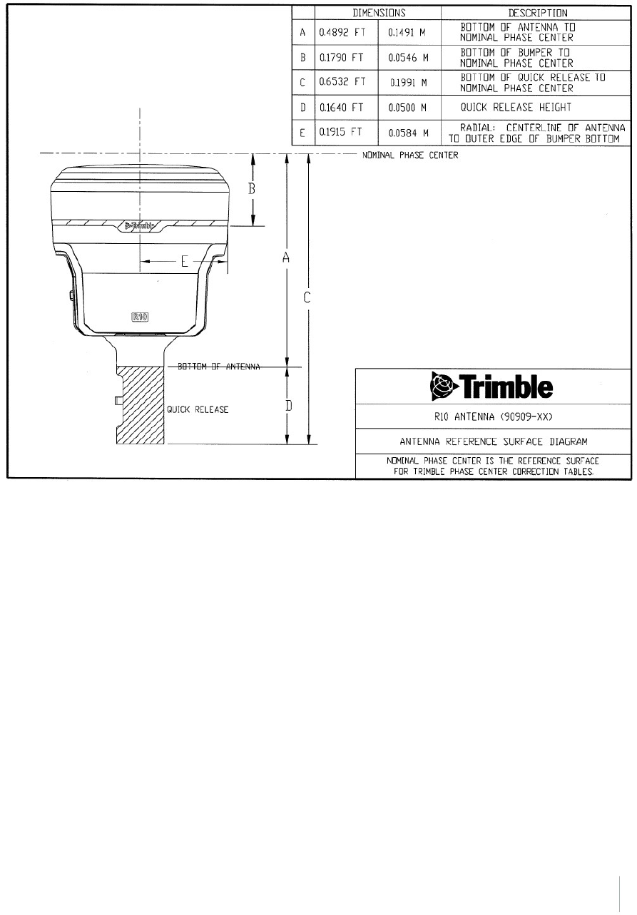
Antenna phase center offsets
Trimble R10 GNSS Receiver User Guide 92
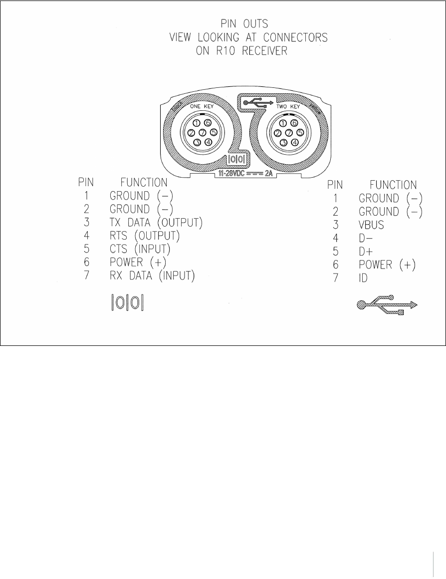
Pinout information
Port 1 is a 7-pin 0-shell Lemo connector that supports RS-232 communications and external power
input. Port 1 has no power outputs.
Port 2 is a 7-pin 0-shell Lemo connector that allows for USB 2.0 communications and external power
input.
Trimble R10 GNSS Receiver User Guide 93

Glossary
1PPS Pulse-per-second. Used in hardware timing. A pulse is generated in conjunction
with a time stamp. This defines the instant when the time stamp is applicable.
almanac A file that contains orbit information on all the satellites, clock corrections, and
atmospheric delay parameters. The almanac is transmitted by a GNSS satellite to a
GNSS receiver, where it facilitates rapid acquisition of GNSS signals when you start
collecting data, or when you have lost track of satellites and are trying to regain
GNSS signals.
The orbit information is a subset of the ephemeris/ephemerides data.
base station Also called reference station. In construction, a base station is a receiver placed at a
known point on a jobsite that tracks the same satellites as an RTK rover, and
provides a real-time differential correction message stream through radio to the
rover, to obtain centimeter level positions on a continuous real-time basis. A base
station can also be a part of a virtual reference station network, or a location at
which GNSS observations are collected over a period of time, for subsequent
postprocessing to obtain the most accurate position for the location.
BeiDou The BeiDou Navigation Satellite System (also known as BDS) is a Chinese satellite
navigation system.
The first BeiDou system (known as BeiDou-1), consists of four satellites and has
limited coverage and applications. It has been offering navigation services mainly
for customers in China and from neighboring regions since 2000.
The second generation of the system (known as BeiDou-2) consists of satellites in a
combination of geostationary, inclined geosynchronous, and medium earth orbit
configurations. It became operational with coverage of China in December 2011.
However, the complete Interface Control Document (which specifies the satellite
messages) was not released until December 2012. BeiDou-2 is a regional navigation
service which offers services to customers in the Asia-Pacific region.
A third generation of the BeiDou system is planned, which will expand coverage
globally. This generation is currently scheduled to be completed by 2020.
broadcast server An Internet server that manages authentication and password control for a network
of VRS servers, and relays VRS corrections from the VRS server that you select.
carrier A radio wave having at least one characteristic (such as frequency, amplitude, or
phase) that can be varied from a known reference value by modulation.
carrier frequency The frequency of the unmodulated fundamental output of a radio transmitter. The
GPS L1 carrier frequency is 1575.42 MHz.
carrier phase Is the cumulative phase count of the GPS or GLONASS carrier signal at a given time.
cellular modems A wireless adaptor that connects a laptop computer to a cellular phone system for
data transfer. Cellular modems, which contain their own antennas, plug into a PC
Card slot or into the USB port of the computer and are available for a variety of
wireless data services such as GPRS.
CMR/CMR+ Compact Measurement Record. A real-time message format developed by Trimble
for broadcasting corrections to other Trimble receivers. CMR is a more efficient
alternative to RTCM.
Trimble R10 GNSS Receiver User Guide 94

Glossary
CMRx A real-time message format developed by Trimble for transmitting more satellite
corrections resulting from more satellite signals, more constellations, and more
satellites. Its compactness means more repeaters can be used on a site.
covariance A statistical measure of the variance of two random variables that are observed or
measured in the same mean time period. This measure is equal to the product of
the deviations of corresponding values of the two variables from their respective
means.
datum Also called geodetic datum. A mathematical model designed to best fit the geoid,
defined by the relationship between an ellipsoid and, a point on the topographic
surface, established as the origin of the datum. World geodetic datums are typically
defined by the size and shape of an ellipsoid and the relationship between the
center of the ellipsoid and the center of the earth.
Because the earth is not a perfect ellipsoid, any single datum will provide a better
model in some locations than in others. Therefore, various datums have been
established to suit particular regions.
For example, maps in Europe are often based on the European datum of 1950 (ED-
50). Maps in the United States are often based on the North American datum of
1927 (NAD-27) or 1983 (NAD-83).
All GPS coordinates are based on the WGS-84 datum surface.
deep discharge Withdrawal of all electrical energy to the end-point voltage before the cell or
battery is recharged.
DGPS See real-time differential GPS.
differential correction Differential correction is the process of correcting GNSS data collected on a rover
with data collected simultaneously at a base station. Because the base station is on a
known location, any errors in data collected at the base station can be measured,
and the necessary corrections applied to the rover data.
Differential correction can be done in real-time, or after the data is collected by
postprocessing.
differential GPS See real-time differential GPS.
DOP Dilution of Precision. A measure of the quality of GNSS positions, based on the
geometry of the satellites used to compute the positions. When satellites are
widely spaced relative to each other, the DOP value is lower, and position precision
is greater. When satellites are close together in the sky, the DOP is higher and GNSS
positions may contain a greater level of error.
PDOP (Position DOP) indicates the three-dimensional geometry of the satellites.
Other DOP values include HDOP(Horizontal DOP) and VDOP (Vertical DOP), which
indicate the precision of horizontal measurements (latitude and longitude) and
vertical measurements respectively. PDOP is related to HDOP and VDOP as follows:
PDOP² = HDOP² + VDOP².
dual-frequency GPS A type of receiver that uses both L1 and L2 signals from GPS satellites. A dual-
frequency receiver can compute more precise position fixes over longer distances
and under more adverse conditions because it compensates for ionospheric delays.
EGNOS European Geostationary Navigation Overlay Service. A Satellite-Based
Augmentation System (SBAS) that provides a free-to-air differential correction
service for GNSS. EGNOS is the European equivalent of WAAS, which is available in
Trimble R10 GNSS Receiver User Guide 95

Glossary
the United States.
elevation The vertical distance from a geoid such as EGM96 to the antenna phase center. The
geoid is sometimes referred to as Mean Sea Level.
elevation mask The angle below which the receiver will not track satellites. Normally set to 10
degrees to avoid interference problems caused by buildings and trees, atmospheric
issues, and multipath errors.
ellipsoid An ellipsoid is the three-dimensional shape that is used as the basis for
mathematically modeling the earth’s surface. The ellipsoid is defined by the lengths
of the minor and major axes. The earth’s minor axis is the polar axis and the major
axis is the equatorial axis.
EHT Height above ellipsoid.
ephemeris/ephemerides A list of predicted (accurate) positions or locations of satellites as a function of time.
A set of numerical parameters that can be used to determine a satellite’s position.
Available as broadcast ephemeris or as postprocessed precise ephemeris.
epoch The measurement interval of a GNSS receiver. The epoch varies according to the
measurement type: for real-time measurement it is set at one second; for
postprocessed measurement it can be set to a rate of between one second and
one minute. For example, if data is measured every 15 seconds, loading data using
30-second epochs means loading every alternate measurement.
feature A feature is a physical object or event that has a location in the real world, which
you want to collect position and/or descriptive information (attributes) about.
Features can be classified as surface or non-surface features, and again as points,
lines/break lines, or boundaries/areas.
firmware The program inside the receiver that controls receiver operations and hardware.
Galileo Galileo is a GNSS system built by the European Union and the European Space
Agency. It is complimentary to GPS and GLONASS.
geoid The geoid is the equipotential surface that would coincide with the mean ocean
surface of the Earth. For a small site this can be approximated as an inclined plane
above the Ellipsoid.
GHT Height above geoid.
GLONASS Global Orbiting Navigation Satellite System. GLONASS is a Soviet space-based
navigation system comparable to the American GPS system. The operational system
consists of 21 operational and 3 non-operational satellites in 3 orbit planes.
GNSS Global Navigation Satellite System.
GSOF General Serial Output Format. A Trimble proprietary message format.
HDOP Horizontal Dilution of Precision. HDOP is a DOP value that indicates the precision of
horizontal measurements. Other DOP values include VDOP (vertical DOP) and
PDOP (Position DOP).
Using a maximum HDOP is ideal for situations where vertical precision is not
particularly important, and your position yield would be decreased by the vertical
component of the PDOP (for example, if you are collecting data under canopy).
height The vertical distance above the Ellipsoid. The classic Ellipsoid used in GPS is WGS-
84.
IBSS Internet Base Station Service. This Trimble service makes the setup of an Internet-
Trimble R10 GNSS Receiver User Guide 96

Glossary
capable receiver as simple as possible. The base station can be connected to the
Internet (cable or wirelessly). To access the distribution server, the user enters a
password into the receiver. To use the server, the user must have a Trimble
Connected Community site license.
L1 The primary L-band carrier used by GPS and GLONASS satellites to transmit satellite
data.
L2 The secondary L-band carrier used by GPS and GLONASS satellites to transmit
satellite data.
L2C A modernized code that allows significantly better ability to track the L2 frequency.
L5 The third L-band carrier used by GPS satellites to transmit satellite data. L5 will
provide a higher power level than the other carriers. As a result, acquiring and
tracking weak signals will be easier.
Mountpoint Every single NTripSource needs a unique mountpoint on an NTripCaster. Before
transmitting GNSS data to the NTripCaster, the NTripServer sends an assignment of
the mountpoint.
MSAS MTSAT Satellite-Based Augmentation System. A Satellite-Based Augmentation
System (SBAS) that provides a free-to-air differential correction service for GNSS.
MSAS is the Japanese equivalent of WAAS, which is available in the United States.
multipath Interference, similar to ghosts on an analog television screen, which occurs when
GNSS signals arrive at an antenna having traversed different paths. The signal
traversing the longer path yields a larger pseudorange estimate and increases the
error. Multiple paths can arise from reflections off the ground or off structures
near the antenna.
NMEA National Marine Electronics Association. NMEA 0183 defines the standard for
interfacing marine electronic navigational devices. This standard defines a number
of 'strings' referred to as NMEA strings that contain navigational details such as
positions. Most Trimble GNSS receivers can output positions as NMEA strings.
NTrip Protocol Networked Transport of RTCM via Internet Protocol (NTrip) is an application-level
protocol that supports streaming Global Navigation Satellite System (GNSS) data
over the Internet. NTrip is a generic, stateless protocol based on the Hypertext
Transfer Protocol (HTTP). The HTTP objects are extended to GNSS data streams.
NTripCaster The NTripCaster is basically an HTTP server supporting a subset of HTTP
request/response messages and adjusted to low-bandwidth streaming data. The
NTripCaster accepts request messages on a single port from either the NTripServer
or the NTripClient. Depending on these messages, the NTripCaster decides whether
there is streaming data to receive or to send.
Trimble NTripCaster integrates the NTripServer and the NTripCaster. This port is
used only to accept requests from NTripClients.
NTripClient An NTripClient will be accepted by and receive data from an NTripCaster, if the
NTripClient sends the correct request message (TCP/UDP connection to the
specified NTripCaster IP and listening port).
NTripServer The NTripServer is used to transfer GNSS data of an NTripSource to the NTripCaster.
An NTripServer in its simplest setup is a computer program running on a PC that
sends correction data of an NTripSource (for example, as received through the
serial communication port from a GNSS receiver) to the NTripCaster.
Trimble R10 GNSS Receiver User Guide 97

Glossary
The NTripServer - NTripCaster communication extends HTTP by additional message
formats and status codes.
NTripSource The NTripSources provide continuous GNSS data (for example, RTCM-104
corrections) as streaming data. A single source represents GNSS data referring to a
specific location. Source description parameters are compiled in the source-table.
OmniSTAR The OmniSTAR HP/XP service allows the use of new generation dual-frequency
receivers with the OmniSTAR service. The HP/XP service does not rely on local
reference stations for its signal, but utilizes a global satellite monitoring network.
Additionally, while most current dual-frequency GNSS systems are accurate to
within a meter or so, OmniSTAR with XP is accurate in 3D to better than 30 cm.
Orthometric elevation The Orthometric Elevation is the height above the geoid (often termed the height
above the 'Mean Sea Level').
PDOP Position Dilution of Precision. PDOP is a DOP value that indicates the precision of
three-dimensional measurements. Other DOP values include VDOP (vertical DOP)
and HDOP (Horizontal Dilution of Precision).
Using a maximum PDOP value is ideal for situations where both vertical and
horizontal precision are important.
POE Power Over Ethernet. Provides DC power to the receiver using an Ethernet cable.
postprocessing Postprocessing is the processing of satellite data after it is collected, in order to
eliminate error. This involves using computer software to compare data from the
rover with data collected at the base station.
QZSS Quasi-Zenith Satellite System. A Japanese regional GNSS eventually consisting of
three geosynchronous satellites over Japan.
real-time differential
GPS
Also known as real-time differential correction or DGPS. Real-time differential GPS is
the process of correcting GPS data as you collect it. Corrections are calculated at a
base station and then sent to the receiver through a radio link. As the rover
receives the position it applies the corrections to give you a very accurate position
in the field.
Most real-time differential correction methods apply corrections to code phase
positions.
While DGPS is a generic term, its common interpretation is that it entails the use of
single-frequency code phase data sent from a GNSS base station to a rover GNSS
receiver to provide sub-meter positionprecision. The rover receiver can be at a
long range (greater than 100 kms (62 miles)) from the base station.
rover A rover is any mobile GNSS receiver that is used to collect or update data in the
field, typically at an unknown location.
Roving mode Roving mode applies to the use of a rover receiver to collect data, stakeout, or
control earthmoving machinery in real time using RTK techniques.
RTCM Radio Technical Commission for Maritime Services. A commission established to
define a differential data link for the real-time differential correction of roving
GNSS receivers. There are three versions of RTCM correction messages. All Trimble
GNSS receivers use Version 2 protocol for single-frequency DGPS type corrections.
Carrier phase corrections are available on Version 2, or on the newer Version 3
RTCM protocol, which is available on certain Trimble dual-frequency receivers. The
Version 3 RTCM protocol is more compact but is not as widely supported as Version
Trimble R10 GNSS Receiver User Guide 98

Glossary
2.
RTK real-time kinematic. A real-time differential GPS method that uses carrier
phasemeasurements for greaterprecision.
SBAS Satellite-Based Augmentation System. SBAS is based on differential GPS, but applies
to wide area (WAAS/EGNOS/MSAS) networks of reference stations. Corrections
and additional information are broadcast using geostationary satellites.
signal-to-noise ratio SNR. The signal strength of a satellite is a measure of the information content of the
signal, relative to the signal’s noise. The typical SNR of a satellite at 30° elevation is
between 47 and 50 dBHz.
skyplot The satellite skyplot confirms reception of a differentially corrected GNSS signal and
displays the number of satellites tracked by the GNSS receiver, as well as their
relative positions.
SNR See signal-to-noise ratio.
Source-table The NTripCaster maintains a source-table containing information on available
NTripSources, networks of NTripSources, and NTripCasters, to be sent to an
NTripClient on request. Source-table records are dedicated to one of the following:
ldata STReams (record type STR)
lCASters (record type CAS)
lNETworks of data streams (record type NET)
All NTripClients must be able to decode record type STR. Decoding types CAS and
NET is an optional feature. All data fields in the source-table records are separated
using the semicolon character.
triple frequency GPS A type of receiver that uses three carrier phase measurements (L1, L2, and L5).
UTC Universal Time Coordinated. A time standard based on local solar mean time at the
Greenwich meridian.
xFill Trimble xFill™ is a new service that extends RTK positioning for several minutes
when the RTK correction stream is temporarily unavailable. The Trimble xFill
service improves field productivity by reducing downtime waiting to re-establish
RTK corrections in black spots. It can even expand productivity by allowing short
excursions into valleys and other locations where continuous correction messages
were not previously possible. Proprietary Trimble xFill corrections are broadcast by
satellite and are generally available on construction sites globally where the GNSS
constellations are also visible. It applies to any positioning task being performed
with a single-base, Trimble Internet Base Station Service (IBSS), or VRS™ RTK
correction source.
VRS Virtual Reference Station. A VRS system consists of GNSS hardware, software, and
communication links. It uses data from a network of base stations to provide
corrections to each rover that are more accurate than corrections from a single
base station.
To start using VRS corrections, the rover sends its position to the VRS server. The
VRS server uses the base station data to model systematic errors (such as
ionospheric noise) at the rover position. It then sends RTCM correction messages
back to the rover.
Trimble R10 GNSS Receiver User Guide 99

Glossary
WAAS Wide Area Augmentation System. WAAS was established by the Federal Aviation
Administration (FAA) for flight and approach navigation for civil aviation. WAAS
improves the accuracy and availability of the basic GNSS signals over its coverage
area, which includes the continental United States and outlying parts of Canada and
Mexico.
The WAAS system provides correction data for visible satellites. Corrections are
computed from ground station observations and then uploaded to two
geostationary satellites. This data is then broadcast on the L1 frequency, and is
tracked using a channel on the GNSS receiver, exactly like a GNSS satellite.
Use WAAS when other correction sources are unavailable, to obtain greater
accuracy than autonomous positions. For more information on WAAS, refer to the
FAA website at http://gps.faa.gov.
The EGNOS service is the European equivalent and MSAS is the Japanese equivalent
of WAAS.
WGS-84 World Geodetic System 1984. Since January 1987, WGS-84 has superseded WGS-
72 as the datum used by GPS.
The WGS-84 datum is based on the ellipsoid of the same name.
Trimble R10 GNSS Receiver User Guide 100