Trimble 9414-450 GPS Data Transciever User Manual
Trimble Navigation Ltd GPS Data Transciever
UserManual.wiki
>
Trimble
>
9414-450 User Manual
>
User Manual
Contents
1.
Operations Manual
2.
User Manual
User Manual
Navigation menu
Upload a User Manual
Namespaces
Wiki Guide
HTML
PDF
Info
Views
User Manual
Discussion / Help
Navigation
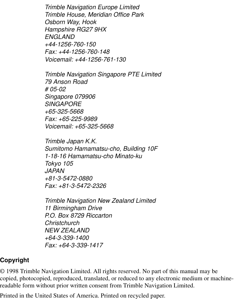


![TRIMMARK 3 User Guide xi PrefaceDocument ConventionsItalics identify software menus, menu commands, dialog boxes, and the dialog box fields.SMALL CAPITALS identify DOS commands, directories, filenames, and filename extensions.Courier represents messages printed on the screen.Courier Bold represents information that you must type in a software screen or window.Helvetica Bold identifies a software command button.[Ctrl] is an example of a hardware function key that you must press on a personal computer (PC). If you must press more than one of these at the same time, this is represented by a plus sign, for example, [Ctrl] + [C].](https://usermanual.wiki/Trimble/9414-450.User-Manual/User-Guide-526913-Page-11.png)
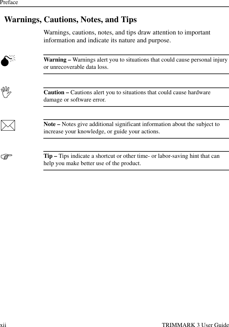


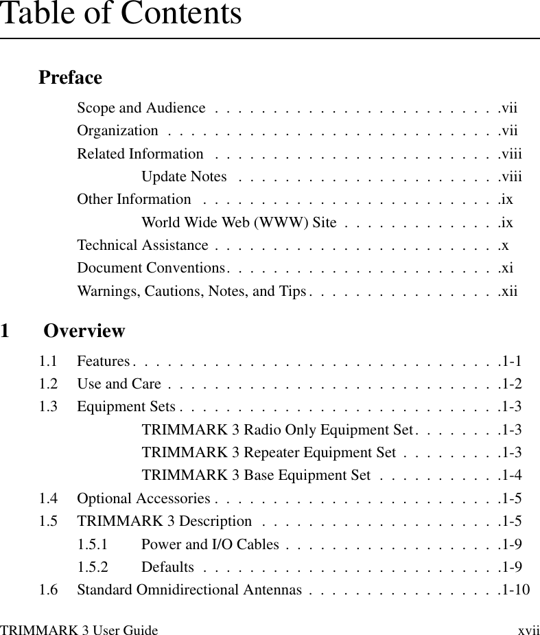


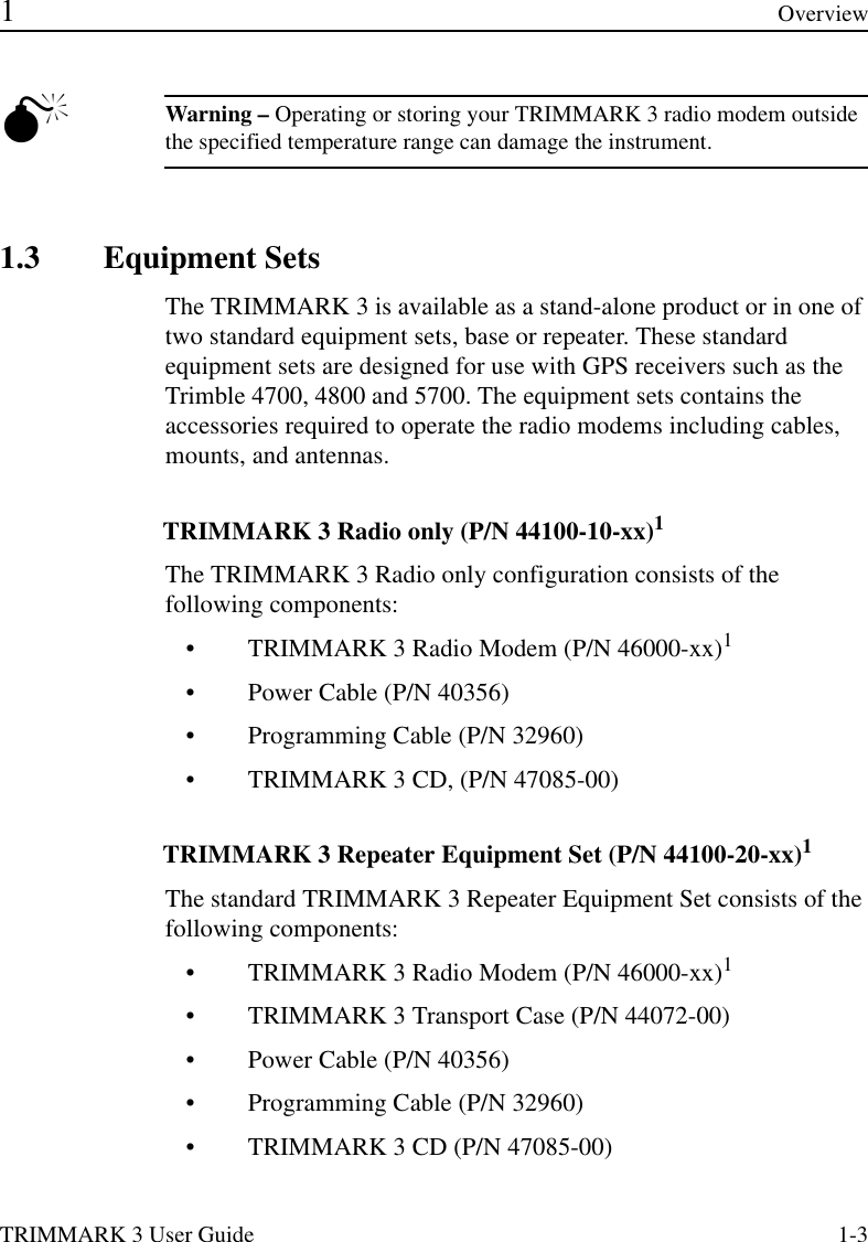


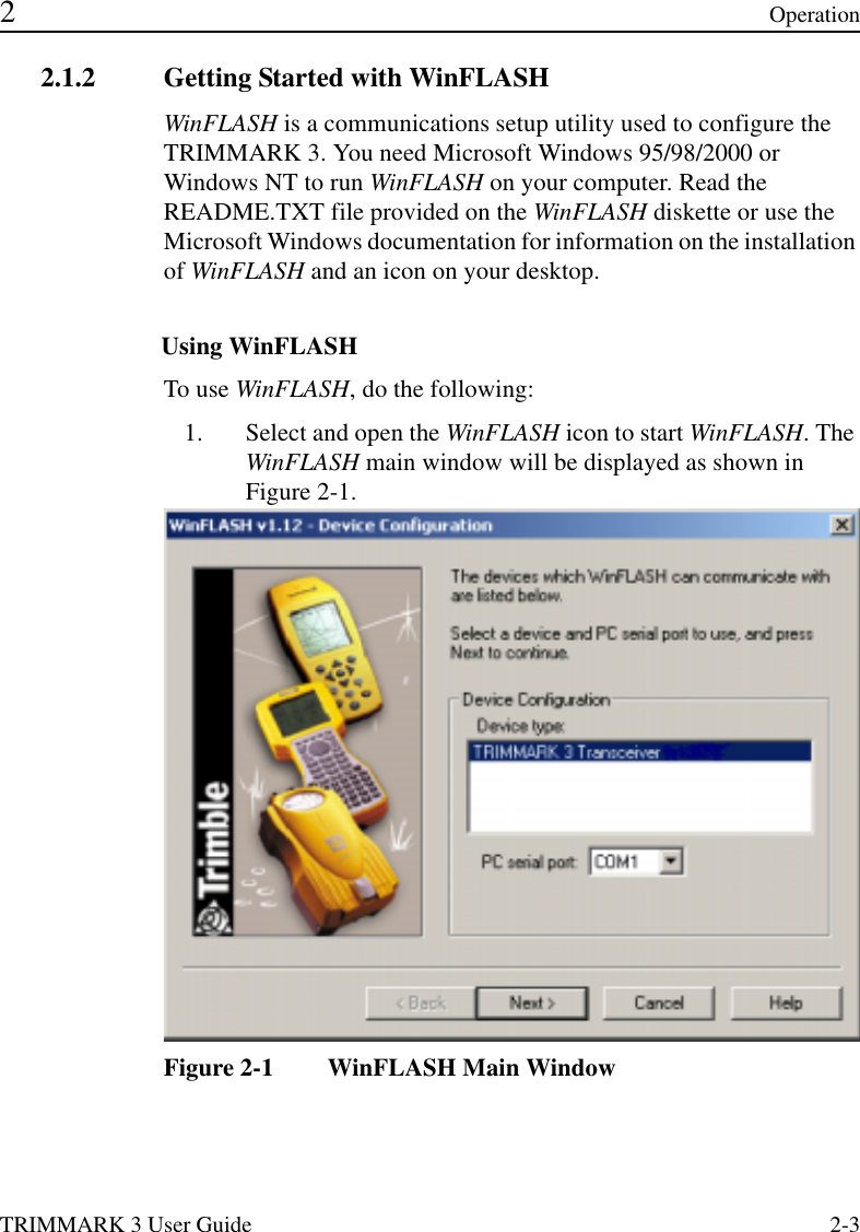
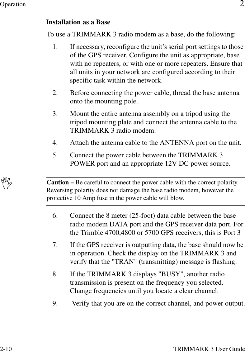
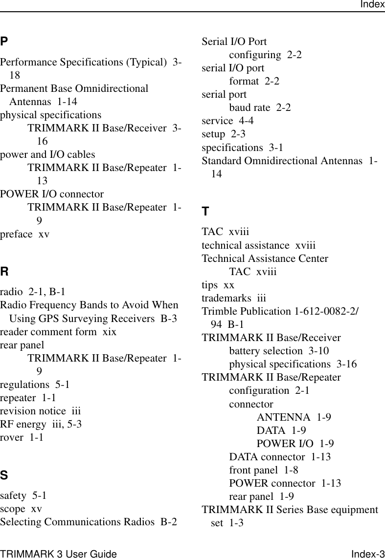
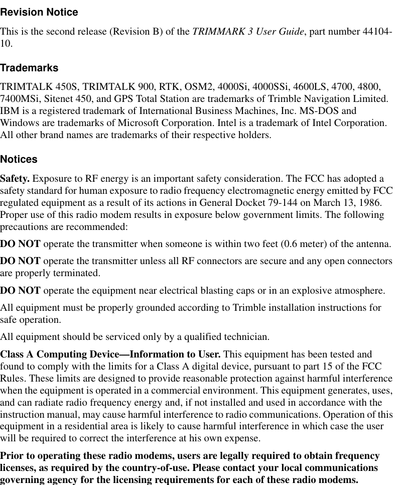
![2-4 TRIMMARK 3 User GuideOperation 22. Follow the directions in the WinFLASH window to make a logical connection to the radio modem.a. Select the appropriate PC serial port (COM port). b. Select the appropriate device, TRIMMARK 3 Transceiver and Press [Next}.The Operation Selection Window as shown in Figure 2-2 appears.Figure 2-2 Operation Selection Window3. Select the appropriate operation in the Operations window, Configure TRIMMARK 3, and Press [Next].a. The Settings Review window appears to confirm you selected operation, Press [Finish].](https://usermanual.wiki/Trimble/9414-450.User-Manual/User-Guide-526913-Page-34.png)
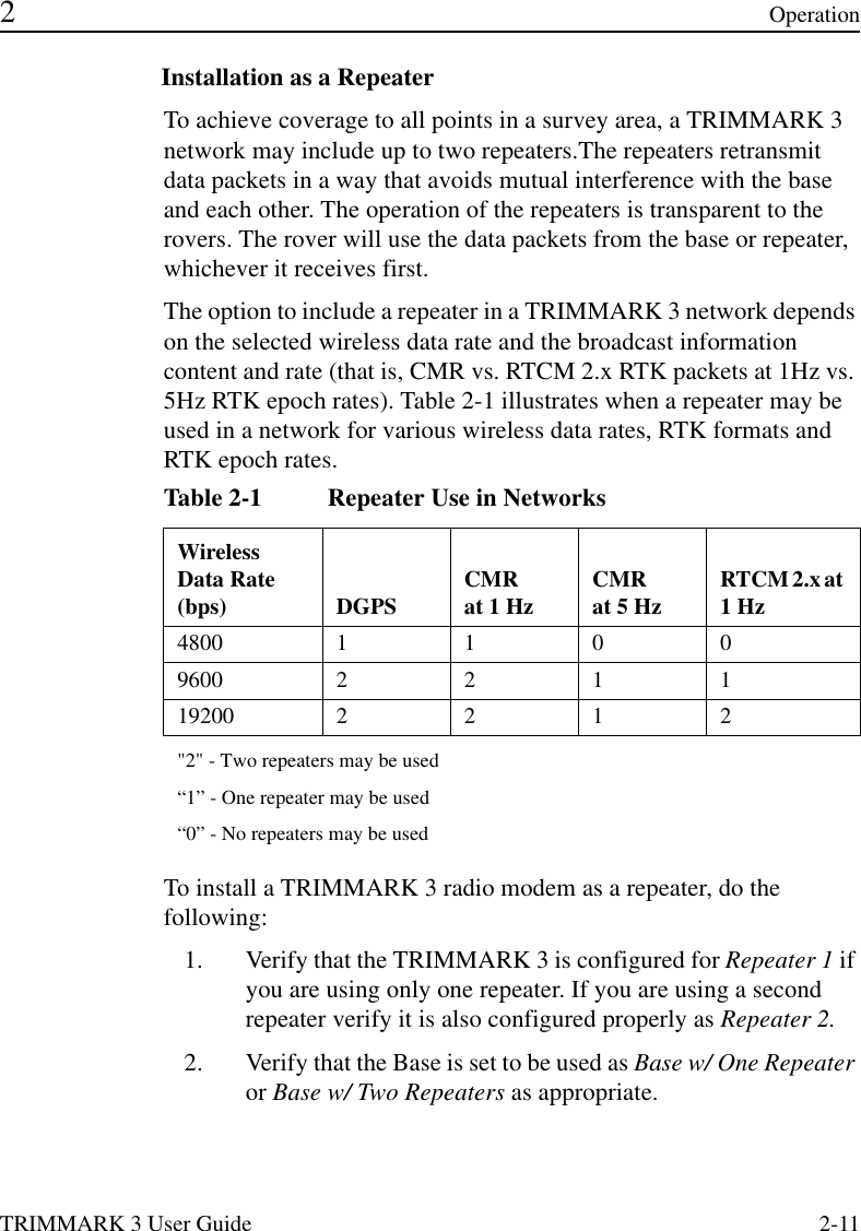
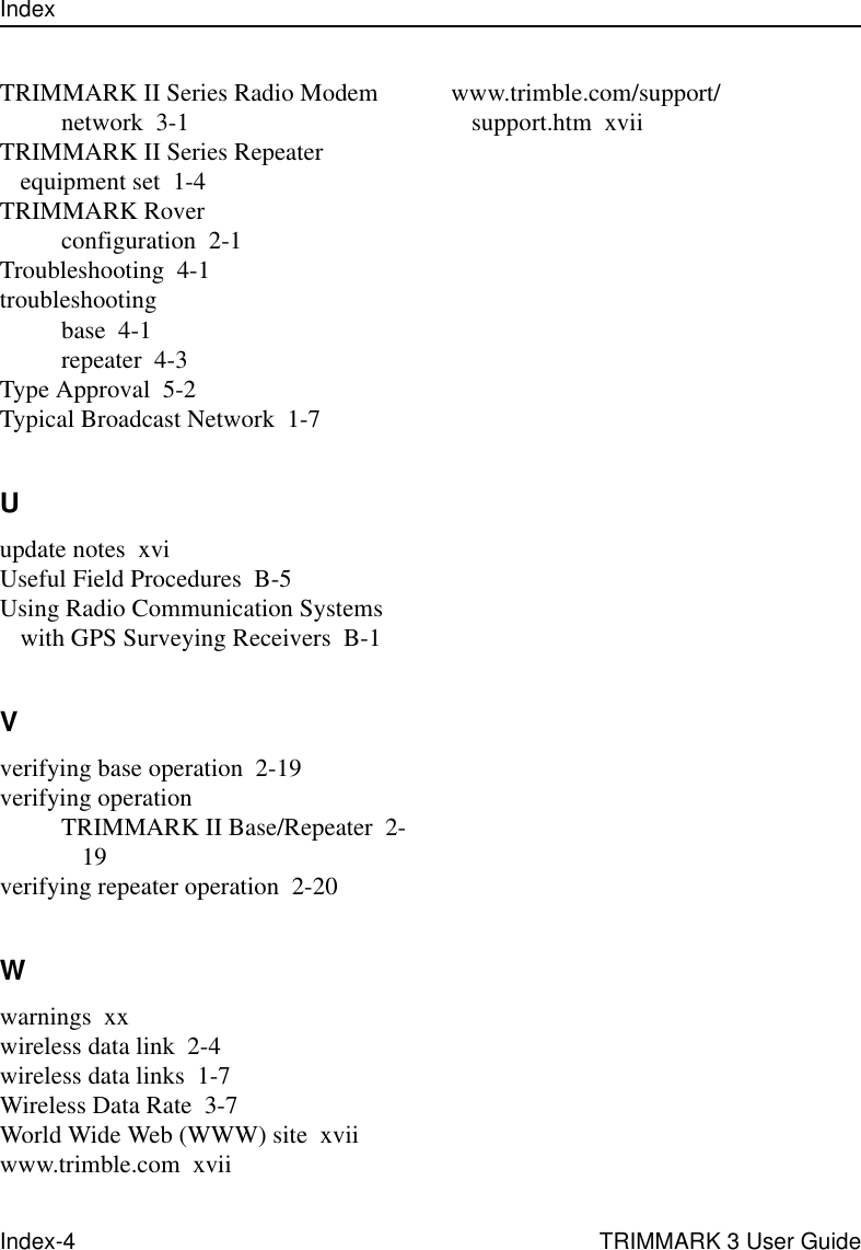
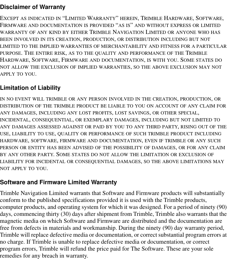
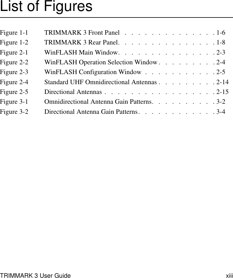
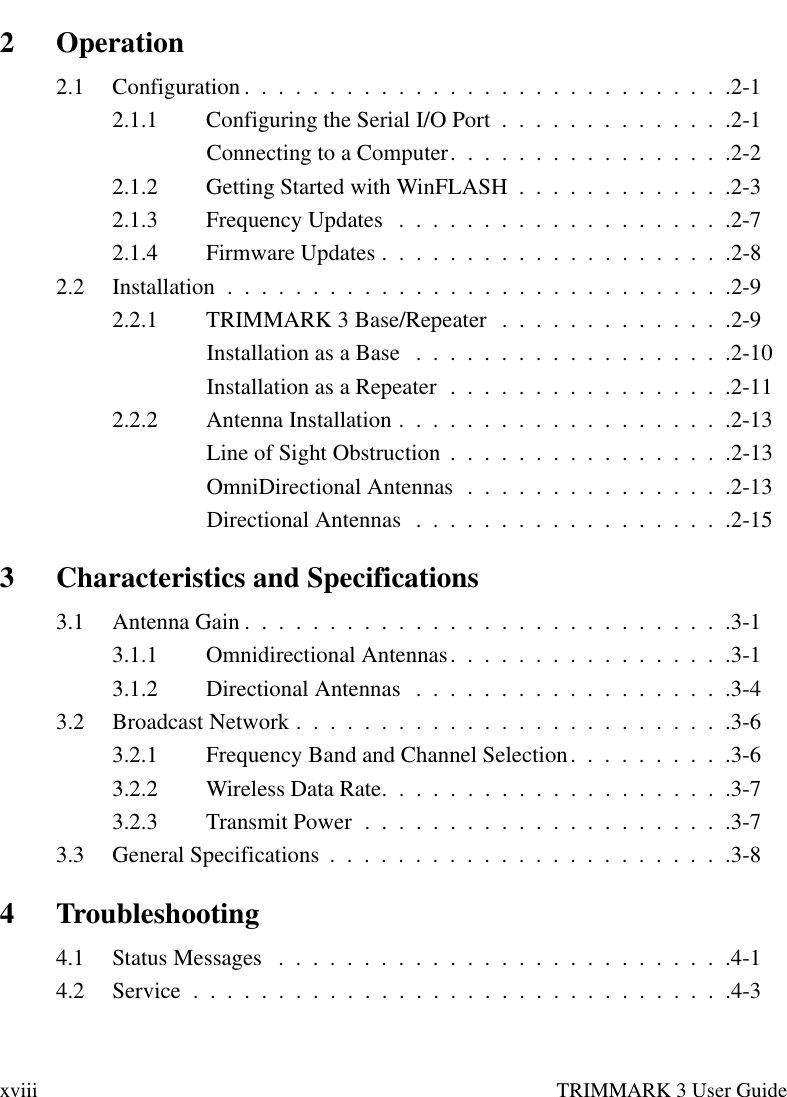
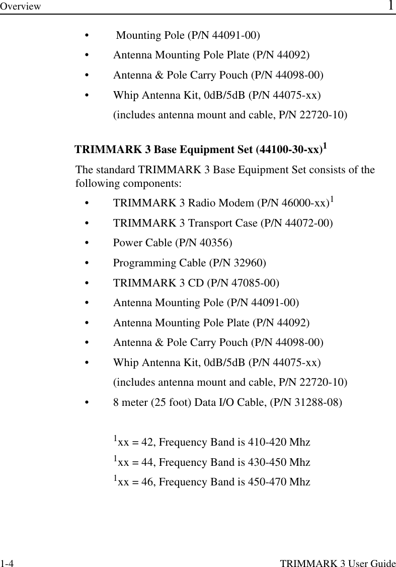
![TRIMMARK 3 User Guide 2-7 2Operation6. In the Wireless Settings dialog, select the appropriate Current Channel, which determines the radio operating frequency. Next, select the desired Wireless Mode, which determines the over-the-air communications settings.Note – All Radios in the network must be configured with the same Wireless Mode Setting, or the radios will not communicate.7. To update the configuration click on the [Set] button. You will then see a Status dialog box. You may now return to the main menu, or exit WinFLASH.8. The [Radio Info] button allows the user to view a text listing of all the radio information, including it’s current configuration.)Tip – You may print or save to file the radio configuration information for future reference. The saved file can be printed and sent via fax or emailed to Trimble Support to aid in troubleshooting radio problems.2.1.3 Frequency List UpdatesThe TRIMMARK 3 radio modem can be programmed with a list of up to 20 frequencies, stored in non-volatile memory. This list is preconfigured based on the frequencies requested when the unit was ordered. Governmental regulations require that only manufacturers or authorized dealers can create this frequency list. All frequencies programmed into a TRIMMARK 3 radio modem must comply with the host country regulations.When you need to change the frequency list (add, delete, or replace frequencies), contact your Trimble dealer and provide the TRIMMARK 3 radio modem’s serial number and an updated list of the frequencies you require. Once you have been provided the frequency file you may upgrade the radio using the WinFLASH utility.](https://usermanual.wiki/Trimble/9414-450.User-Manual/User-Guide-526913-Page-37.png)