Trimble CCKCDPD 46707-00 Crosscheck CDPD User Manual CDPD Book
Trimble Navigation Ltd 46707-00 Crosscheck CDPD CDPD Book
Trimble >
Manual

Part Number 46750-00-ENG
PRELIMINARY - Revision A
January 2002
CrossCheck® CDPD
Mobile Unit Manual

Corporate Office
Trimble Navigation Limited
645 North Mary Avenue
Post Office Box 3642
Sunnyvale, CA 94088-3642
U.S.A.
Phone: +1-408-481-8940, 1-800-545-7762
www.trimble.com
Copyright and Trademarks
© 1997–2002, Trimble Navigation Limited.
All rights reserved.
Printed in the United States of America. Printed
on recycled paper.
The Globe & Triangle, Trimble, Colossus,
EchoLDX, and FirstGPS are trademarks of
Trimble Navigation Limited. The Sextant logo
with Trimble and CrossCheck are trademarks of
Trimble Navigation Limited, registered in the
United States Patent and Trademark Office. All
other trademarks are the property of their
respective owners.
Release Notice
This is January 2002 release (PRELIMINARY -
Revision A) of the CrossCheck® CDPD Mobile
Unit Manual, Part Number 46750-00-ENG. Use
this manual with the EchoLDX Message Terminal
for CrossCheck CDPD and CrossCheck GPRS
Installation and User’s Manual, Trimble part
number 46667-00-ENG.
The following limited warranties give you specific
legal rights. You may have others, which vary
from state/jurisdiction to state/jurisdiction.The
following limited warranties give you specific
legal rights. You may have others, which vary
from state/jurisdiction to state/jurisdiction.
Hardware Limited Warranty
Trimble warrants that this Trimble hardware
product (the “Product”) shall be free from defects
in materials and workmanship and will
substantially conform to Trimble’s applicable
published specifications for the Product for a
period of one (1) year, starting from the date of
delivery. The warranty set forth in this paragraph
shall not apply to software/firmware products.
Software and Firmware License, Limited
Warranty
This Trimble software and/or firmware product
(the “Software”) is licensed and not sold. Its use is
governed by the provisions of the applicable End
User License Agreement (“EULA”), if any,
included with the Software. In the absence of a
separate EULA included with the Software
providing different limited warranty terms,
exclusions, and limitations, the following terms
and conditions shall apply. Trimble warrants that
this Trimble Software product will substantially
conform to Trimble’s applicable published
specifications for the Software for a period of
ninety (90) days, starting from the date of
delivery.
Warranty Remedies
Trimble's sole liability and your exclusive remedy
under the warranties set forth above shall be, at
Trimble’s option, to repair or replace any Product
or Software that fails to conform to such warranty
(“Nonconforming Product”), or refund the
purchase price paid by you for any such
Nonconforming Product, upon your return of any
Nonconforming Product to Trimble in accordance
with Trimble’s standard return material
authorization procedures.

Warranty Exclusions and Disclaimer
These warranties shall be applied only in the event
and to the extent that: (i) the Products and
Software are properly and correctly installed,
configured, interfaced, maintained, stored, and
operated in accordance with Trimble's relevant
operator's manual and specifications, and; (ii) the
Products and Software are not modified or
misused. The preceding warranties shall not apply
to, and Trimble shall not be responsible for defects
or performance problems resulting from (i) the
combination or utilization of the Product or
Software with products, information, data,
systems or devices not made, supplied or specified
by Trimble; (ii) the operation of the Product or
Software under any specification other than, or in
addition to, Trimble's standard specifications for
its products; (iii) the unauthorized modification or
use of the Product or Software; (iv) damage
caused by accident, lightning or other electrical
discharge, fresh or salt water immersion or spray;
or (v) normal wear and tear on consumable parts
(e.g., batteries).
THE WARRANTIES ABOVE STATE TRIMBLE'S
ENTIRE LIABILITY, AND YOUR EXCLUSIVE
REMEDIES, RELATING TO PERFORMANCE OF
THE PRODUCTS AND SOFTWARE. EXCEPT AS
OTHERWISE EXPRESSLY PROVIDED HEREIN,
THE PRODUCTS, SOFTWARE, AND
ACCOMPANYING DOCUMENTATION AND
MATERIALS ARE PROVIDED “AS-IS” AND
WITHOUT EXPRESS OR IMPLIED WARRANTY
OF ANY KIND BY EITHER TRIMBLE
NAVIGATION LIMITED OR ANYONE WHO HAS
BEEN INVOLVED IN ITS CREATION,
PRODUCTION, INSTALLATION, OR
DISTRIBUTION INCLUDING, BUT NOT LIMITED
TO, THE IMPLIED WARRANTIES OF
MERCHANTABILITY AND FITNESS FOR A
PARTICULAR PURPOSE, TITLE, AND
NONINFRINGEMENT. THE STATED EXPRESS
WARRANTIES ARE IN LIEU OF ALL
OBLIGATIONS OR LIABILITIES ON THE PART
OF TRIMBLE ARISING OUT OF, OR IN
CONNECTION WITH, ANY PRODUCTS OR
SOFTWARE. SOME STATES AND
JURISDICTIONS DO NOT ALLOW LIMITATIONS
ON DURATION OR THE EXCLUSION OF AN
IMPLIED WARRANTY, SO THE ABOVE
LIMITATION MAY NOT APPLY TO YOU.
TRIMBLE NAVIGATION LIMITED IS NOT
RESPONSIBLE FOR THE OPERATION OR
FAILURE OF OPERATION OF GPS
SATELLITES OR THE AVAILABILITY OF
GPS SATELLITE SIGNALS.
Limitation of Liability
TRIMBLE’S ENTIRE LIABILITY UNDER ANY
PROVISION HEREIN SHALL BE LIMITED TO
THE GREATER OF THE AMOUNT PAID BY YOU
FOR THE PRODUCT OR SOFTWARE LICENSE OR
U.S.$25.00. TO THE MAXIMUM EXTENT
PERMITTED BY APPLICABLE LAW, IN NO
EVENT SHALL TRIMBLE OR ITS SUPPLIERS BE
LIABLE FOR ANY INDIRECT, SPECIAL,
INCIDENTAL OR CONSEQUENTIAL DAMAGES
WHATSOEVER UNDER ANY CIRCUMSTANCE
OR LEGAL THEORY RELATING IN ANY WAY TO
THE PRODUCTS, SOFTWARE AND
ACCOMPANYING DOCUMENTATION AND
MATERIALS, (INCLUDING, WITHOUT
LIMITATION, DAMAGES FOR LOSS OF
BUSINESS PROFITS, BUSINESS INTERRUPTION,
LOSS OF BUSINESS INFORMATION, OR ANY
OTHER PECUNIARY LOSS), REGARDLESS
WHETHER TRIMBLE HAS BEEN ADVISED OF
THE POSSIBILITY OF ANY SUCH LOSS AND
REGARDLESS OF THE COURSE OF DEALING
WHICH DEVELOPS OR HAS DEVELOPED
BETWEEN YOU AND TRIMBLE. BECAUSE
SOME STATES AND JURISDICTIONS DO NOT
ALLOW THE EXCLUSION OR LIMITATION OF
LIABILITY FOR CONSEQUENTIAL OR
INCIDENTAL DAMAGES, THE ABOVE
LIMITATION MAY NOT APPLY TO YOU.

Notices
Class B Statement – Notice to Users. This
equipment has been tested and found to comply
with the limits for a Class B digital device,
pursuant to Part 15 of the FCC rules. These limits
are designed to provide reasonable protection
against harmful interference in a residential
installation. This equipment generates, uses, and
can radiate radio frequency energy and, if not
installed and used in accordance with the
instructions, may cause harmful interference to
radio communication. However, there is no
guarantee that interference will not occur in a
particular installation. If this equipment does
cause harmful interference to radio or television
reception, which can be determined by turning the
equipment off and on, the user is encouraged to
try to correct the interference by one or more of
the following measures:
–Reorient or relocate the receiving antenna.
–Increase the separation between the equipment
and the receiver.
–Connect the equipment into an outlet on a
circuit different from that to which the receiver
is connected.
–Consult the dealer or an experienced radio/TV
technician for help.
Changes and modifications not expressly
approved by the manufacturer or registrant of this
equipment can void your authority to operate this
equipment under Federal Communications
Commission rules.
Regulatory Approvals CrossCheck CDPD
FCC
The CrossCheck CDPD product complies with the
FCC Part 15, FCC Part 22, and Industry Canada
requirements.
The CrossCheck CDPD product complies with
Part 15 of the FCC rules. Operation is subject to
the following two conditions:
(1) This device may not cause harmful
interference, and
(2) This device must accept any interference
received, including interference that may
cause undesired operation.
FCC ID
This equipment contains FCC ID NBZNRM-6832.

CrossCheck CDPD Mobile Unit Manual v
Contents
About this Manual
Related Information. . . . . . . . . . . . . . . . . . . . . . . . . . . .ix
Technical Assistance . . . . . . . . . . . . . . . . . . . . . . . . . . . x
Your Comments. . . . . . . . . . . . . . . . . . . . . . . . . . . . . .xi
Notes, Cautions, and Warnings . . . . . . . . . . . . . . . . . . . . . .xi
Abbreviations . . . . . . . . . . . . . . . . . . . . . . . . . . . . . . xii
1Overview
Introduction. . . . . . . . . . . . . . . . . . . . . . . . . . . . . . . . 2
Regulatory Approvals - CrossCheck CDPD . . . . . . . . . . . . 2
The CrossCheck CDPD Mobile Unit . . . . . . . . . . . . . . . . . . . 3
CrossCheck CDPD Standard Features . . . . . . . . . . . . . . . 3
CrossCheck CDPD Options . . . . . . . . . . . . . . . . . . . . 4
Antenna Requirements . . . . . . . . . . . . . . . . . . . . . . . 5
CrossCheck CDPD System Accessories . . . . . . . . . . . . . . 5
CrossCheck CDPD Applications . . . . . . . . . . . . . . . . . . . . . 7
The Global Positioning System . . . . . . . . . . . . . . . . . . . . . . 8
GPS Receiver . . . . . . . . . . . . . . . . . . . . . . . . . . . . . . . 8
2 Installation
Introduction . . . . . . . . . . . . . . . . . . . . . . . . . . . . . . . 10
Installing the CrossCheck CDPD Mobile Unit . . . . . . . . . . . . . 10
CrossCheck CDPD Connections . . . . . . . . . . . . . . . . . . . . 11
CDPD Antenna. . . . . . . . . . . . . . . . . . . . . . . . . . 11
Power and Discrete I/O Pinout. . . . . . . . . . . . . . . . . . 12
GPS Antenna . . . . . . . . . . . . . . . . . . . . . . . . . . . 13
MDT Port. . . . . . . . . . . . . . . . . . . . . . . . . . . . . 13

vi CrossCheck CDPD Mobile Unit Manual
Inspecting and Unpacking the Shipment . . . . . . . . . . . . . . . . 14
Installer-Supplied Parts . . . . . . . . . . . . . . . . . . . . . . . . . 15
Mounting the CrossCheck CDPD. . . . . . . . . . . . . . . . . . . . 16
Connecting CrossCheck CDPD to the Vehicle Chassis . . . . . 18
Direct Connection through Mounting Screws . . . . . 19
Connection through the Chassis Ground Wire . . . . . 19
Choosing the GPS Antenna Mounting Location . . . . . . . . . . . . 20
Miniature BulkHead GPS Antenna with Flange (P/N 31192-00) 25
Miniature Bulkhead GPS Antenna without Flange (P/N 32434) 27
Miniature Magnetic GPS Antenna (P/N 37167) . . . . . . . . . 28
Routing the GPS Antenna Cable . . . . . . . . . . . . . . . . . . . . 30
Choosing a CDPD Cellular Antenna Mounting Location . . . . . . . 31
Magnetic Cellular Antenna (P/N 46721). . . . . . . . . . . . . 33
Bulkhead Cellular Antenna (P/N 46730) . . . . . . . . . . . . 34
Routing the Cellular Antenna Cable . . . . . . . . . . . . . . . 38
Connecting the Magnetic Cellular Antenna Cable. . . . . . . . 39
Connecting the Permanent-Mount Cellular Cable . . . . . . . . 39
Inputs (IP0 to IP3) . . . . . . . . . . . . . . . . . . . . . . . . 40
Pulse Counting Inputs (Pulse 0 to Pulse 2) . . . . . . . . . . . 41
Outputs (XP0 to XP2) . . . . . . . . . . . . . . . . . . . . . . 42
CrossCheck CDPD Power . . . . . . . . . . . . . . . . . . . . . . . 44
Connections For Power Management . . . . . . . . . . . . . . 46
Continuous Power Connection (No Power Management) . . . . 48
Installing the EchoLDX Kit . . . . . . . . . . . . . . . . . . . . . . . 50
Configuration Parameters . . . . . . . . . . . . . . . . . . . . 50
Preparing for Installation. . . . . . . . . . . . . . . . . . . . . 50
Inventory . . . . . . . . . . . . . . . . . . . . . . . . 50
Choosing a Location . . . . . . . . . . . . . . . . . . . . . . . 51
Mounting the Pedestal and Installing the EchoLDX. . . . . . . 51
Routing the Power/Data Cable. . . . . . . . . . . . . . . . . . 52
3 Operation
Introduction . . . . . . . . . . . . . . . . . . . . . . . . . . . . . . . 56

CrossCheck CDPD Mobile Unit Manual vii
LED Indicators . . . . . . . . . . . . . . . . . . . . . . . . . . . . . 56
LED States . . . . . . . . . . . . . . . . . . . . . . . . . . . . 57
LED Power-On Sequence . . . . . . . . . . . . . . . . . . . . 57
GPS and CDPD LED States . . . . . . . . . . . . . . . . . . . 58
GPS Receiver Operation . . . . . . . . . . . . . . . . . . . . . . . . 59
A Specifications
Introduction . . . . . . . . . . . . . . . . . . . . . . . . . . . . . . . 62
Standard Components. . . . . . . . . . . . . . . . . . . . . . . . . . 62
Environmental Specifications . . . . . . . . . . . . . . . . . . . . . . 67
I/O Characteristics . . . . . . . . . . . . . . . . . . . . . . . . . . . 69
Accessories (ordered separately) . . . . . . . . . . . . . . . . . . . . 71
CrossCheck CDPD Part Numbers . . . . . . . . . . . . . . . . . . . 71

viii CrossCheck CDPD Mobile Unit Manual

CrossCheck CDPD Mobile Unit Manual ix
About this Manual
Welcome to the CrossCheck® CDPD Mobile Unit Manual. This
manual describes how to install, set up, and troubleshoot the
CrossCheck CDPD product.
Even if you have used other Global Positioning System (GPS)
products before, Trimble recommends that you spend some time
reading this manual to learn about the special features of this product.
If you are not familiar with GPS, visit Trimble’s Web site
(www.trimble.com) for an interactive look at Trimble and GPS.
Trimble assumes that you know how to use a mouse, select options
from menus, and make selections from lists.
Related Information
This manual is available in portable document format (PDF) from the
following Web site:
http://www.trimble.com/support
Use this manual with the EchoLDX™ Message Terminal for
CrossCheck CDPD and CrossCheck GPRS Installation and User’s
Manual, Trimble part number 46667-00-ENG.
Other sources of related information are:
•Release notes – the release notes describe new features of the
product, information not included in the manuals, and any
changes to the manuals. The release notes are available for
download from the above Web address.

About this Manual
x CrossCheck CDPD Mobile Unit Manual
•The Fleet Management and Mobile Asset Tracking section of
the Trimble Web site – application notes, technical notes, and
other useful product information are available from this site.
These documents contain important information about software
and hardware changes.
•ftp.trimble.com – use the Trimble FTP site to send files or to
receive files such as software patches, utilities, service bulletins,
and FAQs. Alternatively, access the FTP site from the Trimble
Web site: www.trimble.com/support.
Technical Assistance
If you have a problem and cannot find the information you need in the
product documentation, contact your local Distributor.
Prospective resellers (not under contract) can get general information
about the CrossCheck CDPD by sending email to:
sales_info@trimble.com
or by searching the Web site for information such as the
CrossCheck CDPD data sheet.
Existing resellers can obtain additional information about the
CrossCheck CDPD by sending email to:
crosscheck@trimble.com
or by contacting your local sales office or sales engineer.

About this Manual
CrossCheck CDPD Mobile Unit Manual xi
Your Comments
Your feedback about the supporting documentation helps us to
improve it with each revision. To forward your comments, do one of
the following:
•Send an e-mail to ReaderFeedback@trimble.com.
•Complete the Reader Comment Form at the back of this manual
and mail it according to the instructions at the bottom of the
form.
If the reader comment form is not available, send comments and
suggestions to the address in the front of this manual. Please mark it
Attention: Technical Publications Group.
Notes, Cautions, and Warnings
Notes, cautions, and warnings are used to emphasize important
information.
Note – Notes provide additional significant information about the
subject to increase your knowledge, or guide your actions.
,Caution – Cautions alert you to situations that could cause hardware
damage or software error.
Warning – Warnings alert you to situations that could cause personal
injury.
About this Manual
xii CrossCheck CDPD Mobile Unit Manual
Abbreviations
The following abbreviations are used in this manual:
Abbreviation Definition
AVL Automatic Vehicle Location
CrossCheck CrossCheck CDPD may be referred to simply as
CrossCheck.
Echo
LDX
or MDT The Echo
LDX
Message Terminal is referred to as the
Echo
LDX
or sometimes as the Mobile Data Terminal
(MDT).
GPS
Global Positioning System
OTA Over the air
TMS Trimble Mobile Solutions Division
WLG Wireless Location Gateway


1 Overview
2 CrossCheck CDPD Mobile Unit Manual
1.1 Introduction
This manual describes the CrossCheck CDPD Mobile Unit which is
designed to be used with Trimble’s Wireless Location Gateway
(WLG) for Fleet Asset Management and Automatic Vehicle Location
(AVL) purposes.
The CrossCheck CDPD runs the firmware necessary to communicate
with the Wire Location Gateway and automatically reports location-
based information such as position, speed, and direction, and when the
vehicle stops or exceeds a specified speed. It also provides information
such as vehicle run time and mileage and is programmable over the air
(OTA) by the gateway. Configuration parameters, or the entire code
set, can be changed.
1.1.1 Regulatory Approvals - CrossCheck CDPD
FCC
The CrossCheck CDPD product complies with the FCC Part 15 Class B and
and Part 22 (from OEM module), and Industry Canada requirements.
The CrossCheck CDPD product complies with Part 15 of the FCC rules.
Operation is subject to the following two conditions:
(1) This device may not cause harmful interference, and
(2) This device must accept any interference received, including interference
that may cause undesired operation.

CrossCheck CDPD Mobile Unit Manual 3
Overview 1
1.2 The CrossCheck CDPD Mobile Unit
The CrossCheck CDPD Mobile Unit is housed in a single, compact
enclosure that simplifies installation and provides greater reliability.
This package is a mobile communications system module for
Automatic Vehicle Location (AVL) and fleet asset management
applications. It operates over the CDPD cellular network and allows
simple, fast, and efficient transfer of information between a vehicle
and Trimble’s Web-based gateway.
The CrossCheck CDPD Mobile Unit integrates the following into a
single package:
•A CDPD cellular transceiver module
•A high-sensitivity, 8-channel GPS receiver
•The controller, featuring the proprietary firmware and
integrated datalogging functions
The product’s features and functions are not identical to other
products in the CrossCheck family, such as the CrossCheck AMPS
CrossCheck GSM, and CrossCheck XR.
Note – The CrossCheck CDPD does not support the IQEventEngine
firmware used by other CrossCheck products and does not support the
TAIP protocol.
1.2.1 CrossCheck CDPD Standard Features
The CrossCheck CDPD automatically reports arrival or departure
from an area that has been previously defined via a Site Dispatching
message, that can include either a new Job Site to be attended or a
return to the Base or Home Site. CrossCheck CDPD also allows
various asset utilization calculations.

1 Overview
4 CrossCheck CDPD Mobile Unit Manual
The CrossCheck CDPD includes the following:
•Eight-channel GPS receiver
•A sophisticated event handler that allows the
CrossCheck CDPD to be configured over the air (OTA) to
respond to a wide variety of dispatch and fleet asset
management operations
•One serial port for Mobile Data Terminal (MDT) operation
•Extensive discrete I/O inputs, pulse counters, and outputs for
vehicle peripheral support
•Configurable Zone Logic Configuration packet:
–Geo-fence area for Job Sites
–Geo-fence area for Home Sites
–Entry Speed Limit for Site Dispatch purposes
–Exit Speed Limit for Site Dispatch purposes
–Site dispatch time-out
–Minimum duration time to detect entry/exit regions
•Support for datalogging that allows the CrossCheck CDPD to
store events and positions for up to 1 week while out of the
network. Each item is checked for the 1-week expiration and
discarded if appropriate.
1.2.2 CrossCheck CDPD Options
The following option is available: EchoLDX™ Message Terminal
(MDT), the messaging user-interface component of a fleet asset-
management system.
The EchoLDX terminal connects to the CrossCheck CDPD to receive
and display text messages, Job Sites, and Home Sites from the
Wireless Location Gateway.

CrossCheck CDPD Mobile Unit Manual 5
Overview 1
1.2.3 Antenna Requirements
CDPD and GPS antennas are required for operation. Bulkhead and
magnetic mount GPS antennas are available from Trimble. Chapter 2
describes the antennas and antenna installation.
The standard CrossCheck CDPD configuration does not include a
GPS or CDPD antenna because the type of antenna required depends
on the application. Antennas must be ordered separately. For more
information, see Appendix A, Specifications.
1.2.4 CrossCheck CDPD System Accessories
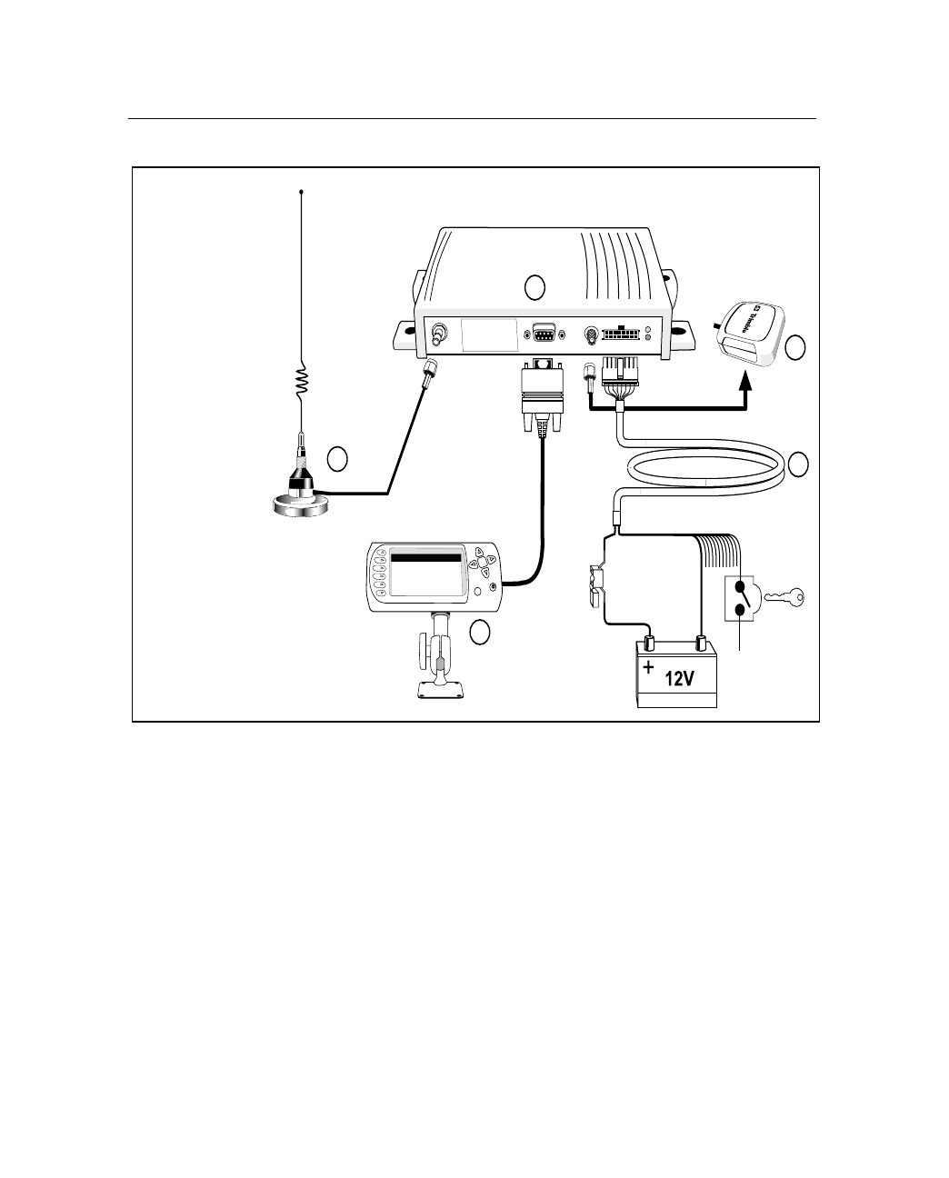
Figure 1.1 illustrates the CrossCheck CDPD Mobile Unit and
accessories.
1. CrossCheck CDPD Mobile Unit
2. EchoLDX Message Terminal Kit . The kit includes:
–EchoLDX Terminal
–Power/Data cable
–Pedestal Mounting Kit
–Quick Reference Guide
3. Power and discrete I/O cable
4. GPS antenna with cable and SMA-p connector
5. CDPD antenna with cable and TNC-p connector
1 Overview
6 CrossCheck CDPD Mobile Unit Manual
Figure 1.1 CrossCheck CDPD Mobile Unit and Accessories
Ignition
Sense
3
CDPD
Antenna
4
Warning: All persons must
be at least 20 cm from
antenna when transmitter
operating to meet FCC RF
exposure requirements.
1
2
CrossCheck CDPD
Echo
LDX
Antenna
GPS
5

CrossCheck CDPD Mobile Unit Manual 7
Overview 1
1.3 CrossCheck CDPD Applications
The Trimble Mobile Solutions (TMS) Division provides you with the
core products around which you can build systems and applications
for managing your transport and logistics assets.
TMS products and services address the need for an end-to-end
solution. They provide the building blocks at both ends of the asset
management system including the on-board units mounted in the
vehicle and the Trimble Web-based gateway for dispatch and control
applications anywhere.
The on-board components are centered on the CrossCheck CDPD
receiver. You can use the receiver as a standalone unit, or you can
interface it with external accessories and sensors to make it function as
part of an on-board system.
The optional EchoLDX Message Terminal provides a driver interface
to exchange messages or generate event reports.
The CrossCheck CDPD and applications can do the following:
•Automate vehicle status changes for dispatching applications
•Determine time spent and distance traveled on jobs for
accounts-payable systems
•Improve efficiency by detecting unauthorized vehicle stops or
off-route activities
•Improve customer service by alerting customer-service systems
of delays
•Drive compliance by keeping a time-stamped log of activities
•Improve safety by indicating speed limit violations
•Identify unauthorized use of equipment and detect theft

1 Overview
8 CrossCheck CDPD Mobile Unit Manual
1.4 The Global Positioning System
The Global Positioning System (GPS) is a satellite-based navigation
system operated and maintained by the U.S. Department of Defense.
GPS consists of a constellation of 24 satellites providing world-wide,
24-hour, three-dimensional (3D) coverage. Although originally
conceived for military needs, GPS has a broad array of civilian
applications including timing, surveying, fleet management, marine,
land, aviation, and vehicle navigation.
GPS is the most accurate technology available for navigation. As a
satellite-based system, GPS is immune from the limitations of land-
based systems, which have limited coverage and whose accuracy
varies with geographic location and, even under ideal conditions,
cannot compare with GPS.
By computing the distance to GPS satellites orbiting the earth, a GPS
receiver can calculate an accurate position. This process is called
satellite ranging. GPS receivers can also provide precise time, speed,
and course measurements which are important for vehicle mobile
positioning and communications applications.
1.5 GPS Receiver
The CrossCheck CDPD includes an advanced GPS receiver, which
provides the position, course, speed and time information required for
AVL and fleet management applications. A brief overview of the GPS
receiver’s architecture and operation is provided in the next paragraph.
The CrossCheck CDPD’s GPS receiver features an eight-channel
digital signal processor (DSP) which operates at the GPS L1
frequency (1575.42 MHz) and processes the Coarse/Acquisition (C/A)
code portion of the GPS signal. The RF and digital signal-processing
components of the GPS module are custom integrated circuits
designed by Trimble.

CHAPTER
2
Installation 2
■Introduction
■Installing the CrossCheck CDPD Mobile Unit
■CrossCheck CDPD Connections
■Inspecting and Unpacking the Shipment
■Installer-Supplied Parts
■Mounting the CrossCheck CDPD
■Choosing the GPS Antenna Mounting Location
■Routing the GPS Antenna Cable
■Choosing a CDPD Cellular Antenna Mounting Location
■CrossCheck CDPD Power
■Installing the Echo
LDX
Kit

2 Installation
10 CrossCheck CDPD Mobile Unit Manual
2.1 Introduction
This chapter presents instructions for installing the CrossCheck CDPD
Mobile Unit in a vehicle.
Warning – The CrossCheck CDPD and its antennas and accessories
should only be professionally installed by Trimble Authorized dealers.
Warning – To meet FCC RF exposure requirements, the maximum gain
for externally mounted antennas (plus any cable losses) cannot be more
than 3 dBi.
Warning – To meet FCC RF exposure requirements, all persons must be
at least 20 cm from the CDPD antenna when the transmitter is operating.
2.2 Installing the CrossCheck CDPD Mobile Unit
The CrossCheck CDPD Mobile Unit can be installed before or after
configuring its firmware. For example, you might want to configure all
of the units for a fleet of vehicles prior to installation.
Note – If you plan to install the CrossCheck CDPD receiver before
installing the EchoLDX Message Terminal, be sure to leave adequate
clearance to the Mobile Data Terminal port and other connectors.
Adequate clearance must exist to connect the MDT to the unit, and you
must be able to read the LED indicators if troubleshooting is required.
CrossCheck CDPD Mobile Unit Manual 11
Installation 2
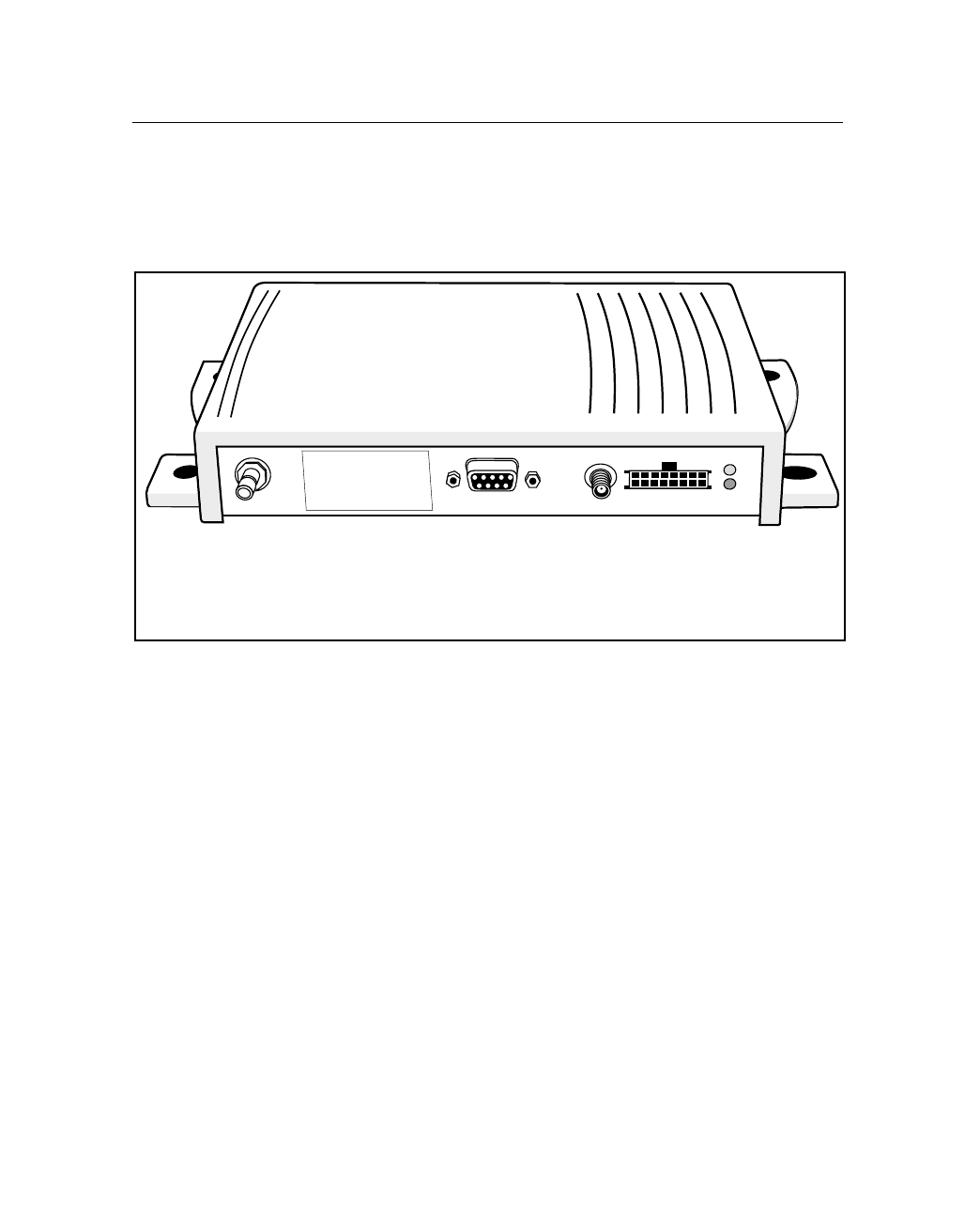
2.3 CrossCheck CDPD Connections
This section describes the CrossCheck CDPD component
connections. Figure 2.1 shows the CrossCheck CDPD connections.
Figure 2.1 CrossCheck CDPD Connections
2.3.1 CDPD Antenna
The CrossCheck CDPD uses a TNC connector for the CDPD antenna.
For more information, see Appendix A.
1234
Warning: All persons must
be at least 20 cm from
antenna when transmitter
operating to meet FCC RF
exposure requirements.
1 Antenna TNC receptacle
2 MDT port
3 GPS antenna
4 Power and discrete I/O

2 Installation
12 CrossCheck CDPD Mobile Unit Manual
2.3.2 Power and Discrete I/O Pinout
Table 2.1 lists how the power and discrete I/O cable carriers signals.
Table 2.1 CrossCheck CDPD Connections
Pin Signal Function Length (Ft.)
1V
GATT
Input: Power 9-32V 16
2 GND Battery Ground 3
3 CHAS Chassis Ground 3
4 GND Ground 3
5 IGN Input: Ignition Sense 16
6 IP3 Discrete Input 3 3
7 IP2 Discrete Input 2 3
8 XP2 Discrete Output 2 3
9 IP1 Discrete Input 1 3
10 XP1 Discrete Output 1 3
11 IPO Discrete Input 0 3
12 XPO Discrete Output 0 3
13 Pulse 0 Pulse Input 0 3
14 Pulse 1 Pulse Input 1 3
15 Pulse 2 Pulse Input 2 3
16 8V AUX 8 VDC Auxiliary output 3
CrossCheck CDPD Mobile Unit Manual 13
Installation 2
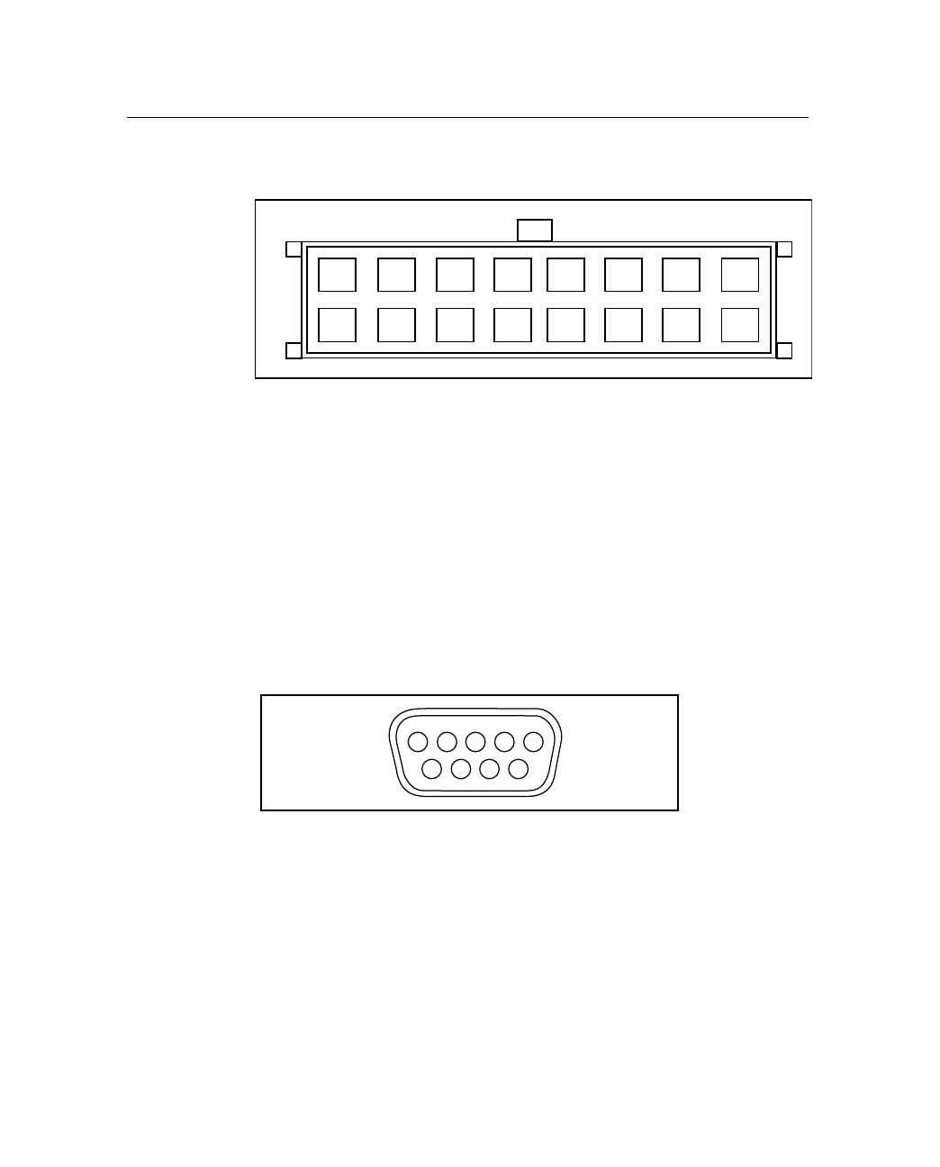
Figure 2.2 illustrates the power and discrete I/O pinout.
Figure 2.2 Power and Discrete I/O Pinout
2.3.3 GPS Antenna
The GPS antenna uses an SMA female connector. For more
information, see Appendix A.
2.3.4 MDT Port
Figure 2.3 illustrates the MDT port pin configuration, a standard 9-pin
DCE configuration.
Figure 2.3 MDT Pinout
12108642
1197531
14
16
13
15
12345
6789

2 Installation
14 CrossCheck CDPD Mobile Unit Manual
Table 2.2 lists the MDT connector pinout.
2.4 Inspecting and Unpacking the Shipment
The CrossCheck CDPD may be shipped in one or more cartons,
depending on the number of units and the options ordered with the
shipment. Before opening the shipping containers, inspect the cartons
for punctures or damage and immediately report any damage to the
shipping carrier. Then open the shipping cartons individually and
check their contents against the packing slip.
Table 2.2 MDT Connector Pinout
Pin Signal Connection
1 DCD Output: Carrier Detect
2 RxD Output: Serial Data
3 TxD Input: Serial Data
4 DTR Input: Data Terminal Ready
5 GND Ground
6 DSR Output: Data Set Ready
7 RTS Input: Request to Send
8 CTS Output: Clear to Send
9 PWR Output: 8.5 VCD @ 200 mA max.
(Interpreted as RS-232 hi-level.)

CrossCheck CDPD Mobile Unit Manual 15
Installation 2
Table 2.3 identifies the CrossCheck CDPDs and bundles and the
included components.
Additional cartons may be included in the shipment for GPS and
cellular antennas interface cables, and EchoLDX Kit options. For a
complete listing of CrossCheck CDPD and component part numbers,
see Appendix A, Table A.16.
2.5 Installer-Supplied Parts
The installer must supply the following parts:
•Mounting fasteners for the CrossCheck CDPD
•Fasteners for mounting the GPS antenna if the antenna is the
bulkhead type
•Cable ties for securing cables to the vehicle
•Any special connectors and adapters required to connect
interface devices and power leads (power and I/O cable supplied
only with the CrossCheck CDPD Starter Kit P/N 46720-00)
•GPS antenna (supplied only with the CrossCheck CDPD P/N
46720-00 but also available as separate accessory item)
•CDPD Cellular antenna (supplied only with the CrossCheck
CDPD Starter Kit P/N 46720-00, but also available as separate
accessory item)
Note – The required accessories are not supplied with the Ten Pack
Bundles.
Table 2.3 CrossCheck CDPD Units and Bundles
Part Number Description
46720-00 CrossCheck CDPD Starter Kit (includes GPS antenna,
CDPD cellular antenna, power and I/O cable, and Echo
LDX
Kit ).
46720-10 CrossCheck CDPD Ten Pack (includes 10 CrossCheck
CDPDs without GPS antennas or accessories).

2 Installation
16 CrossCheck CDPD Mobile Unit Manual
2.6 Mounting the CrossCheck CDPD
The CrossCheck CDPD can be installed inside any type of vehicle and
in any orientation. It can be installed in an enclosed compartment or in
a location with limited accessibility, as long as the environmental
specifications are maintained to ensure reliable operation. For
example, the CrossCheck CDPD can be installed on the floor under a
seat, or on a wall behind a seat.
Note – The CrossCheck CDPD cannot be installed inside the engine
compartment, wheel well, chassis, or on any exterior surface of the
vehicle.
Choose a location for the CrossCheck CDPD that allows for
convenient routing and connection of the antenna and interface cables,
and that has access to a power source. When selecting a mounting
location, consider the specifications listed in Appendix A, and avoid
the following hazards:
•Direct exposure to weather
•Excessive heat (exhaust manifolds)
•Excessive cold (refrigeration units)
•High-vibration areas (engine compartment, transmission)
•Corrosive fluids and gases (acids, petroleum products)
•Direct exposure to water
(The CrossCheck CDPD is not waterproof.)
To mount the CrossCheck CDPD:
1. Choose the mounting location.
The CrossCheck CDPD can be mounted horizontally, vertically,
or in any convenient orientation. During normal system
operation, you do not need to see the CrossCheck CDPD LED
indicators. However, the ability to see the LED indicators is a
definite advantage when troubleshooting the unit.
CrossCheck CDPD Mobile Unit Manual 17
Installation 2
The integral mounting flange is designed to secure the
CrossCheck CDPD to a flat surface. The flange has four holes
for securing the unit with fasteners.
2. Use self-tapping screws or machine screws to secure the unit to
the mounting surface.
,Caution – Over-stressing the plastic mounting surface when
tightening the mounting screws can cause the plastic to crack. Use
washers sized small enough that they do not tighten down on the
plastic cover of the CrossCheck CDPD when the mounting screws are
secured. Tightening screws without using washers can lead to
compressing, cracking, or deforming the mounting surface.
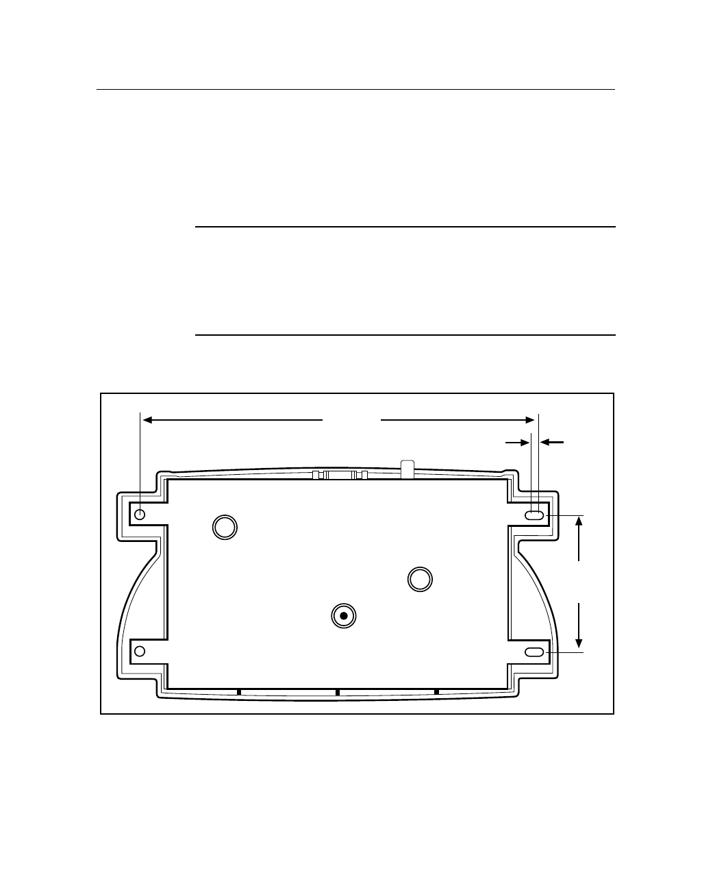
Figure 2.4 shows the mounting dimensions.
Figure 2.4 CrossCheck CDPD Mounting Dimensions (in millimeters)
4.8
205.5
69.9

2 Installation
18 CrossCheck CDPD Mobile Unit Manual
The installer must provide an appropriate selection of fasteners to
secure the CrossCheck CDPD to the mounting surface.
•When using self-tapping screws:
–Select an appropriate size and length for the mounting
surface.
–The hole size leaves some allowance for holes drilled
slightly off center from the specified dimensions.
•When using machine screws:
–Trimble recommends the use of number m3.5
(or number 6) pan-head machine screws.
–Select a screw length, which extends a safe distance
beyond the mounting surface.
–Secure the screw with a washer and nut. Lock washers are
recommended to prevent vehicle vibration from loosening
the fasteners.
2.6.1 Connecting CrossCheck CDPD to the Vehicle Chassis
For proper operation, the aluminum chassis of the CrossCheck CDPD
must be connected electrically (grounded) to the chassis of the vehicle
on which it installed. This can be accomplished in two ways:
•Direct connection through metal screws (preferred)
•Connection through the chassis ground wire

CrossCheck CDPD Mobile Unit Manual 19
Installation 2
Direct Connection through Mounting Screws
To mount the CrossCheck CDPD Mobile Unit on a metal surface that
is permanently attached to the vehicle chassis (for example, the base
of the trunk, or a mounting plate that is permanently attached to the
chassis using metal screws):
1. Fasten down the CrossCheck CDPD using metal screws driven
through the metal tabs on the sides of the unit.
2. Use star washers to ensure a reliable electrical contact to the
metal tabs.
3. Make sure the screws are tight, and that they make contact both
with the metal on the CrossCheck CDPD and with the vehicle
chassis.
Note – If this direct connection through mounting screws method is
used for chassis connection, then the chassis ground (pin 3 on the
power and discrete I/O connector) on the CrossCheck CDPD should
be left unconnected.
Connection through the Chassis Ground Wire
If the CrossCheck CDPD cannot be mounted directly on a metal
surface that is attached to the vehicle, then use the chassis ground wire
(pin 3 on the power and discrete I/O connector) to make electrical
contact to the vehicle chassis:
1. Use a wire with gauge of at least 18 AWG to connect the
CrossCheck CDPD power connector to the vehicle chassis.
2. Use a metal screw with a star washer to ensure a reliable
electrical contact to the vehicle chassis.
3. Keep the wire length as short as possible by selecting a
connection point in the vehicle chassis that is close to the
CrossCheck CDPD.

2 Installation
20 CrossCheck CDPD Mobile Unit Manual
2.7 Choosing the GPS Antenna Mounting Location
Antenna location is critical for optimum GPS performance. When
choosing a location for the GPS antenna, consider these guidelines:
•The antenna has an unobstructed view of the sky.
•The antenna is safe from damage during normal vehicle
operation and maintenance.
•The antenna is not shielded from satellite signals by metal
objects or other impenetrable materials.
GPS signals can penetrate plastic, glass and tinted glass (except
metallized glass), fiberglass, and plexiglass materials as long as the
surface is relatively dry. GPS satellite signals do not penetrate metal or
dense wood.
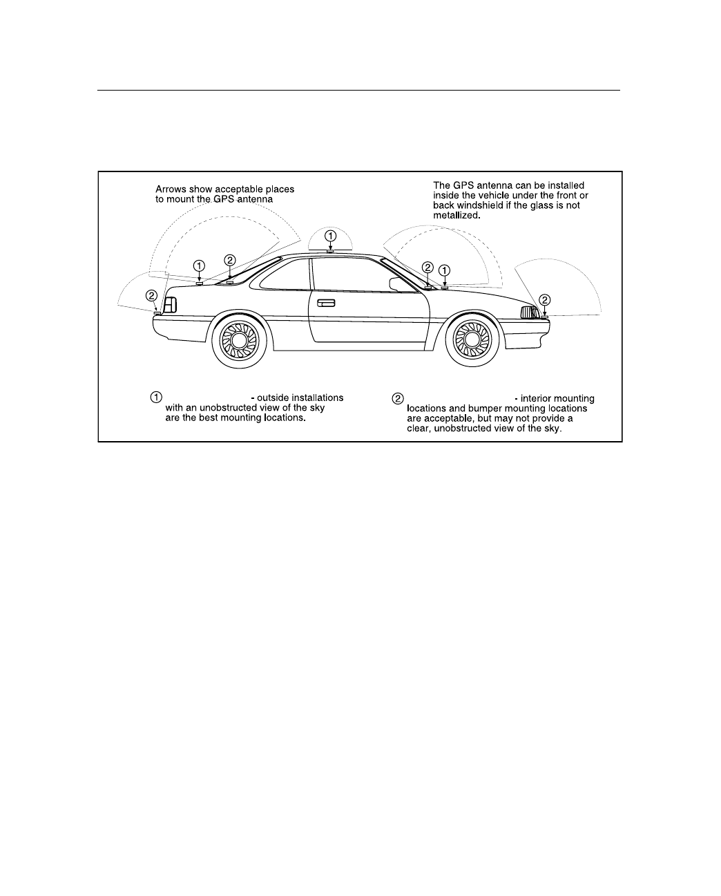
Since GPS satellite signals can penetrate plastic, fiberglass, and glass,
the GPS antenna can also be installed on a dashboard under a sloped
windshield (if the windshield is not metallized) or under a plastic
fender or bumper. These alternative locations are likely to offer less
satellite coverage, since the metal components of the vehicle shield the
antenna from portions of the sky.
,Caution – Do not mount the GPS antenna under a metallized glass
windshield, such as those used in some vehicles for window de-
fogging or de-icing systems. However, the GPS antenna can be
mounted under a tinted-glass windshield.
Disclaimer - The instructions included in this section apply to the
GPS antennas sold by Trimble and may not apply to third-party
products. There are many other GPS antennas available on the
market which may or may not be compatible with the
CrossCheck CDPD, including combined GPS/CDPD cellular
antenna solutions which have not yet been tested and certified
by Trimble.

CrossCheck CDPD Mobile Unit Manual 21
Installation 2
Additional guidelines to follow include:
•Mount the antenna in a horizontal position facing the sky, as
shown in Figure 2.5.
If the antenna must be located in the vicinity of other antennas
(radio, cellular phone), locate the GPS antenna at least 46 cm
(approximately 18 in.) away.
•Avoid areas of high vibration (for example, engine hoods).
For permanent installations, choose a location with access both
above and below the antenna-mounting surface. This access is
required for installing fasteners and for routing the antenna
cable.
Note – The standard length of magnetic-mount and bulkhead-
mount GPS antenna cables supplied by Trimble is 5 m
(approximately 16 ft.). Longer bulkhead-mount antenna cables
can be prepared by the installer using the guidelines presented
in Appendix A.
CrossCheck CDPD Mobile Unit Manual 23
Installation 2
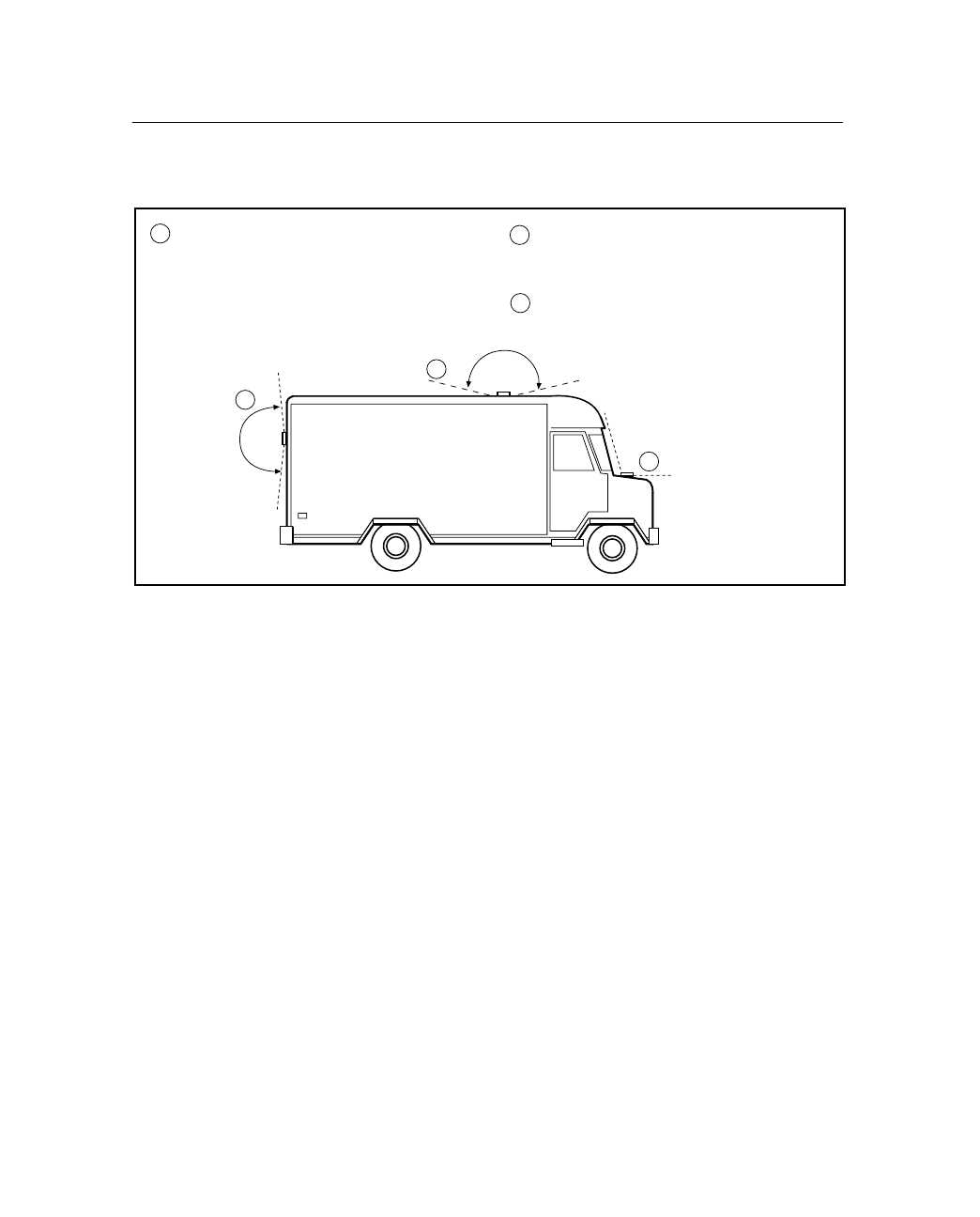
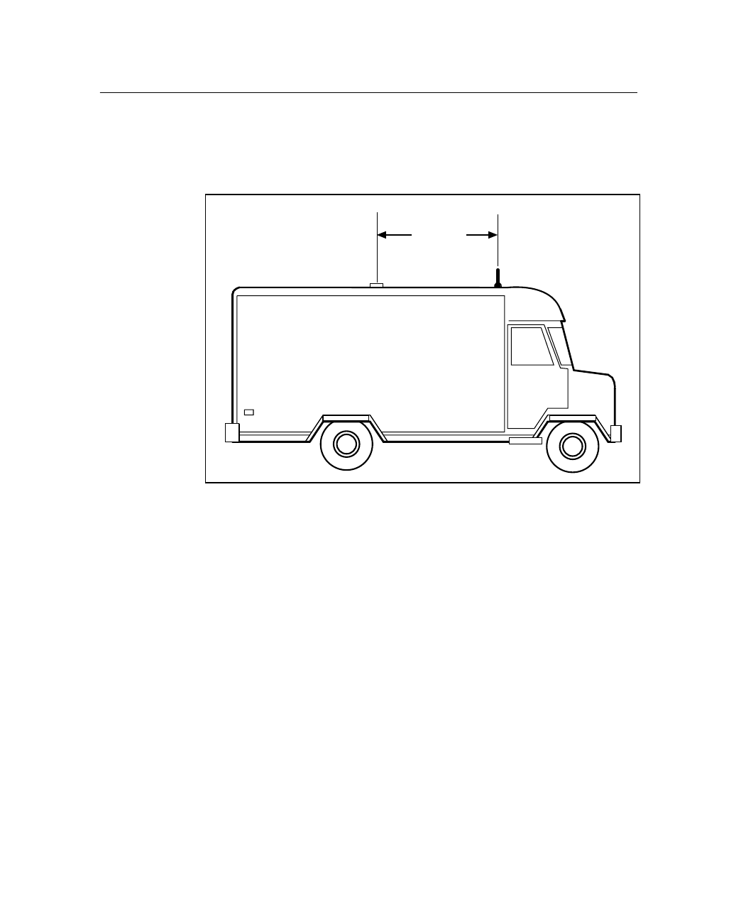
Figure 2.6 shows the typical antenna mounting locations for a van.
Figure 2.6 Antenna Mounting Locations for Van
.
Reduced Performance - avoid locations
where the antenna does not have a
clear unobstructed view of the sky
2
1
3
2
1
Unacceptable Locations
3
Best Performance the GPS antenna
should be mounted in a location with
a clear unobstructed view of the sky
2 Installation
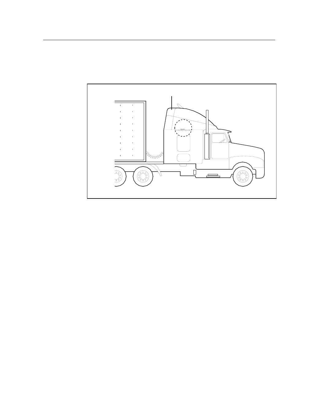
24 CrossCheck CDPD Mobile Unit Manual
The antenna can be mounted under a fiberglass wind deflector such as
those used on conventional and cabover trucks as shown in Figure 2.7.
Make sure the wind deflector is not painted with a metallic finish.
Figure 2.7 Antenna Mounted under Fiberglass Canopy
Note – The GPS antenna may be subject to performance degradation
when covered by a heavy layer of snow or ice. If these are typical
conditions for your application, mount the antenna in an accessible
location so snow can be easily removed.
The CrossCheck CDPD can receive GPS signals from one of two
types of optional Miniature Bulkhead GPS antennas, or a Miniature
Magnetic GPS antenna, all available from Trimble. Follow the
applicable procedure (below) to mount the GPS antenna.
Note: Must be
fiberglass
CrossCheck CDPD Mobile Unit Manual 25
Installation 2
2.7.1 Miniature BulkHead GPS Antenna with Flange
(P/N 31192-00)
Two cables are available for the Miniature Bulkhead Antenna with
Flange:
•A straight TNC-Plug-to-SMA-Plug antenna cable (P/N 36107)
•A right-angle TNC-Plug-to-straight SMA-Plug antenna cable
(P/N 36106)
For more information, see Appendix A.
Figure 2.8 shows the Miniature Bulkhead GPS antenna mounting.
Figure 2.8 Miniature Bulkhead GPS antenna with Flange (P/N 31192-00)
Mounting hardware.
Only two of four sets
shown for clarity.
Gasket
Cable
Mounting Lug
2 Installation
26 CrossCheck CDPD Mobile Unit Manual
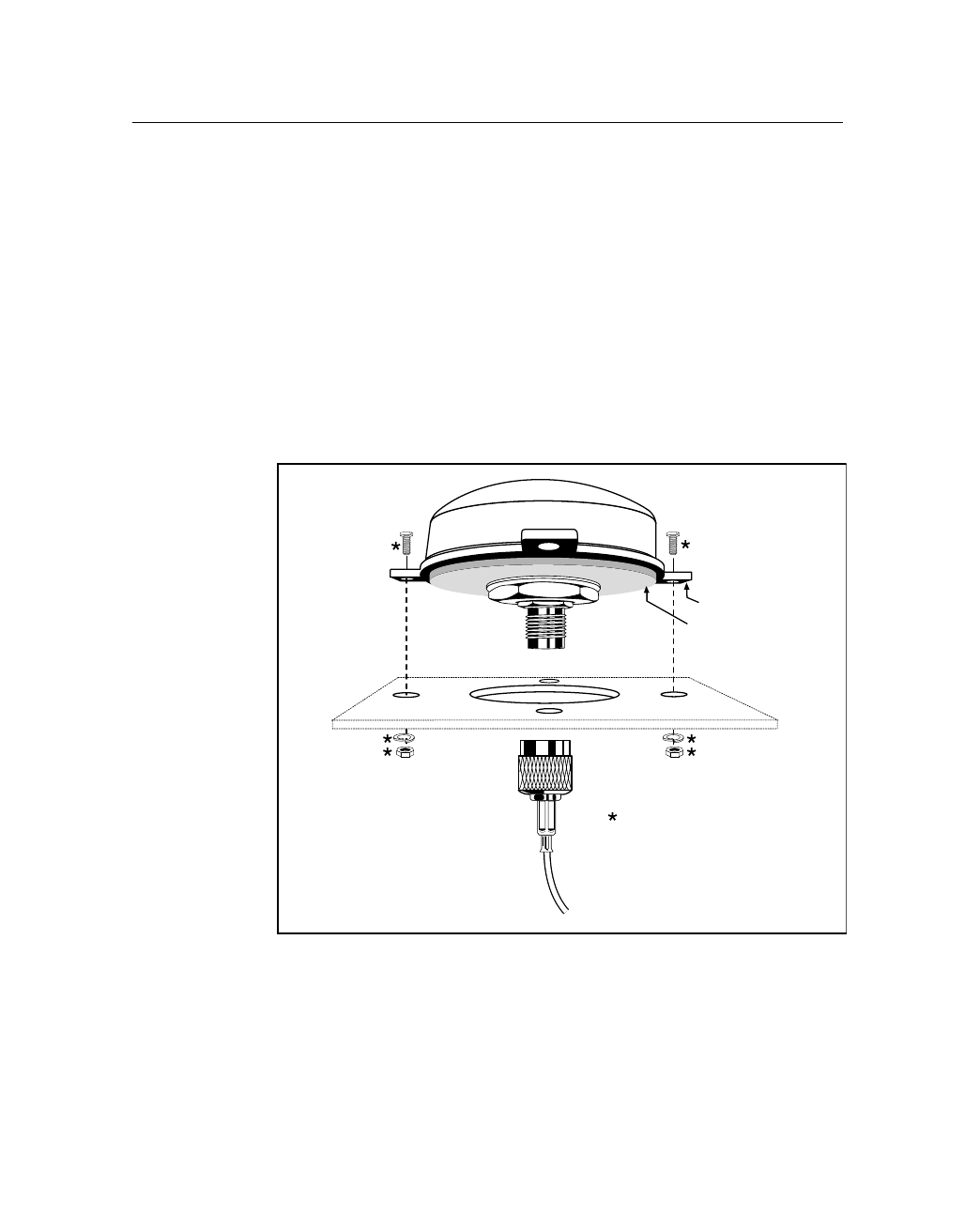
To mount the Miniature Bulkhead GPS antenna with Flange:
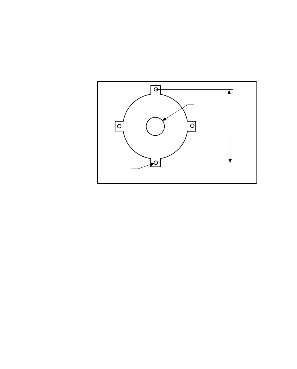
1. Drill holes in the mounting surface using the antenna mounting
template shown in Figure 2.9.
Figure 2.9 Mounting Hole Dimensions
2. Slip the antenna through the larger hole in the center of the hole
pattern and rotate the antenna until the four holes in the antenna
mounting flange are aligned to the hole circle.
3. Secure the antenna with the four screws, lock washers, and nuts.
4. Connect the TNC connector on the antenna cable to the TNC
connector on the antenna.
5. Route the cable to the CrossCheck CDPD mounting location.
Use cable ties to secure the cable along the routing path.
For detailed cable routing guidelines, see Routing the GPS Antenna
Cable on page 2-30.
7.6 cm
(3.0 in)
19 mm
(0.75 in)
3.8 mm
(0.15 in)
CrossCheck CDPD Mobile Unit Manual 27
Installation 2
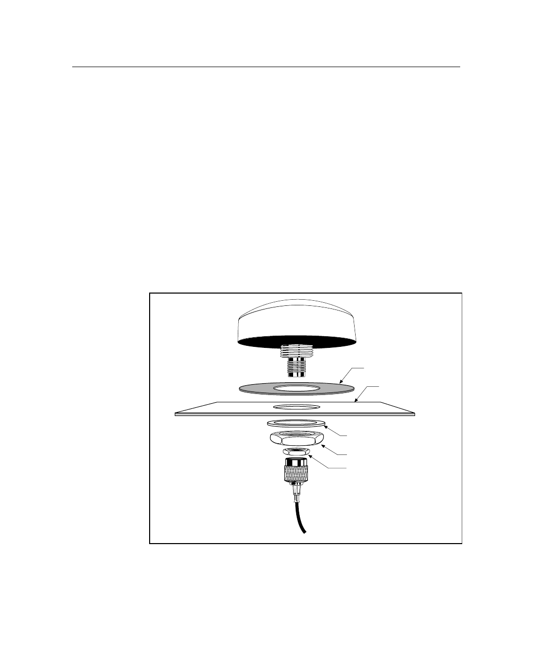
2.7.2 Miniature Bulkhead GPS Antenna without Flange
(P/N 32434)
Two cables are available for the Miniature Bulkhead Antenna
without Flange:
•A straight TNC-Plug-to-SMA-Plug antenna cable (P/N 36107)
•A right-angle TNC-Plug-to-straight-SMA-Plug antenna cable
(P/N 36106)
Check the metal thickness at the mounting location before drilling the
mounting hole. The bulkhead mount on the antenna is designed to
attach to metal surfaces with a thickness of 48 mm (0.1875 in.) or less.
Figure 2.10 illustrates the antenna without the flange. For more
information, see Appendix A.
Figure 2.10 Miniature Bulkhead GPS Antenna without Flange (P/N 32434)
Gasket
Sheet Metal
Mounting Nut
Jam Nut
Metal Washer

2 Installation
28 CrossCheck CDPD Mobile Unit Manual
To mount the antenna:
1. Choose the antenna mounting location (see Choosing the GPS
Antenna Mounting Location on page 2-20).
2. Drill a 19 mm (0.75 in.) hole at the mounting location.
3. Remove the large nut from the bottom of the antenna.
4. Mount the gasket as shown in Figure 2.10.
5. Slip the antenna through the mounting hole, and secure it with
the large nut.
6. Connect the antenna cable as shown in Figure 2.10.
7. Route the cable to the CrossCheck CDPD mounting location.
8. Connect the cable to the GPS antenna connector.
For detailed cable routing guidelines, see Routing the GPS Antenna
Cable on page 2-30.
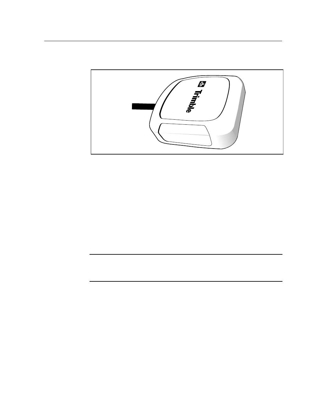
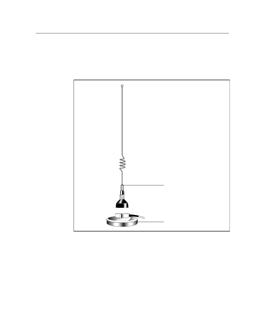
2.7.3 Miniature Magnetic GPS Antenna (P/N 37167)
The Miniature Magnetic Antenna features a magnetic mount for
attaching the unit to ferrous metal surfaces and an integral 5-m cable
with SMA connector.
,Caution – The magnetic-mount antenna cable has no strain relief at
the antenna end of the cable and is not recommended for permanent
installations.
CrossCheck CDPD Mobile Unit Manual 29
Installation 2
Figure 2.11 illustrates the miniature antenna.
Figure 2.11 Miniature Magnetic GPS Antenna
To mount the Magnetic GPS Antenna:
1. Choose the antenna mounting location (see Choosing the GPS
Antenna Mounting Location on page 2-20).
2. Mount the antenna to a ferrous surface.
3. Route the antenna cable.
The antenna features a permanent antenna cable which must be routed
to the location where the CrossCheck CDPD is mounted.
,Caution – The magnetic-mount antenna cable is exposed to the
environment. Wind could cause damage to the cable; use tie wraps to
secure the cable along its route.
See Routing the GPS Antenna Cable in the next section.

2 Installation
30 CrossCheck CDPD Mobile Unit Manual
2.8 Routing the GPS Antenna Cable
The Magnetic GPS Antenna has an integral antenna cable, and the
Miniature Bulkhead GPS Antennas have a separate 5-m
(approximately 16 ft.) cable.
If you are using one of the Miniature Bulkhead GPS Antennas, attach
the antenna cable to the connector on the base of the antenna prior to
routing the cable. When routing the cable, start at the antenna and
choose the most direct path to the CrossCheck CDPD while observing
the following guidelines:
•Make sure that at least 5.1 cm (2 in.) of clearance exists
between the CrossCheck CDPD's antenna connector and the
nearest obstacle.
•Make all cable bends, especially the bend at the SMA strain
relief to the antenna connector, with at least 1.3 cm (0.5 in.)
bend radius.
•Provide an adequate service loop when routing the cable around
vehicle hinges to ensure that the cable is not pinched when a
hinged door opens or closes.
•Make sure that the coax cable is not routed through areas where
vehicle movement can abrade the cable surface.
•Never coil the excess antenna cable, particularly the Magnetic
GPS antenna cable. A coiled cable can act as an antenna and
may receive interference.
•Protect cables from exposure to corrosive fluids.
Once the cable is routed and secured, attach the cable to the
CrossCheck CDPD GPS (SMA) connector.

CrossCheck CDPD Mobile Unit Manual 31
Installation 2
2.9 Choosing a CDPD Cellular Antenna
Mounting Location
,Caution – This product can be used with an externally mounted
antenna of no more than 3db of gain. A minimum separation distance
of 20 cm (approximately 8 in.) must be maintained between the
radiating CDPD antenna and the user for this device to satisfy the
RF Exposure requirements of the FCC
Disclaimer - The instructions included in this section apply to the
cellular antennas sold by Trimble and may not apply to third-party
products. There are many other cellular antennas available on the
market which may or may not be compatible with the
CrossCheck CDPD, including combined GPS/Cellular antenna
solutions which have not yet been tested and certified by Trimble.
Although not as critical as GPS antenna placement, cellular antenna
placement is also important. Mount the cellular whip antenna in a
vertical orientation in a location where it is safe from damage during
normal vehicle operation and maintenance. Automated vehicle washes
may damage misplaced cellular antennas.
2 Installation
32 CrossCheck CDPD Mobile Unit Manual
Maintain a separation of at least 46 cm (or approximately 18 in.)
between the cellular (or other) and GPS antennas (as illustrated in
Figure 2.12).
Figure 2.12 Distance Between Antenna Locations
In general, the greater the separation, the less chance of interference.
For permanent antenna installations, choose a location with access
both above and below the antenna mounting surface. This access is
required for installing fasteners and for routing the antenna cable.
Cellular phone dealers and installers are experts on cellular antenna
placement. For some installations, the installer may substitute a glass-
mount antenna for the antenna supplied by Trimble. Other antennas
are acceptable as long as they conform to the requirements listed in
Appendix A.
Trimble offers two cellular antenna options for the
CrossCheck CDPD. The Magnetic Antenna is recommended for
temporary installations. A Bulkhead Antenna is recommended for
permanent, surface-mount installations.
46cm
(18 in)
minimum
GPS
Antenna
Cellular
Antenna
CrossCheck CDPD Mobile Unit Manual 33
Installation 2
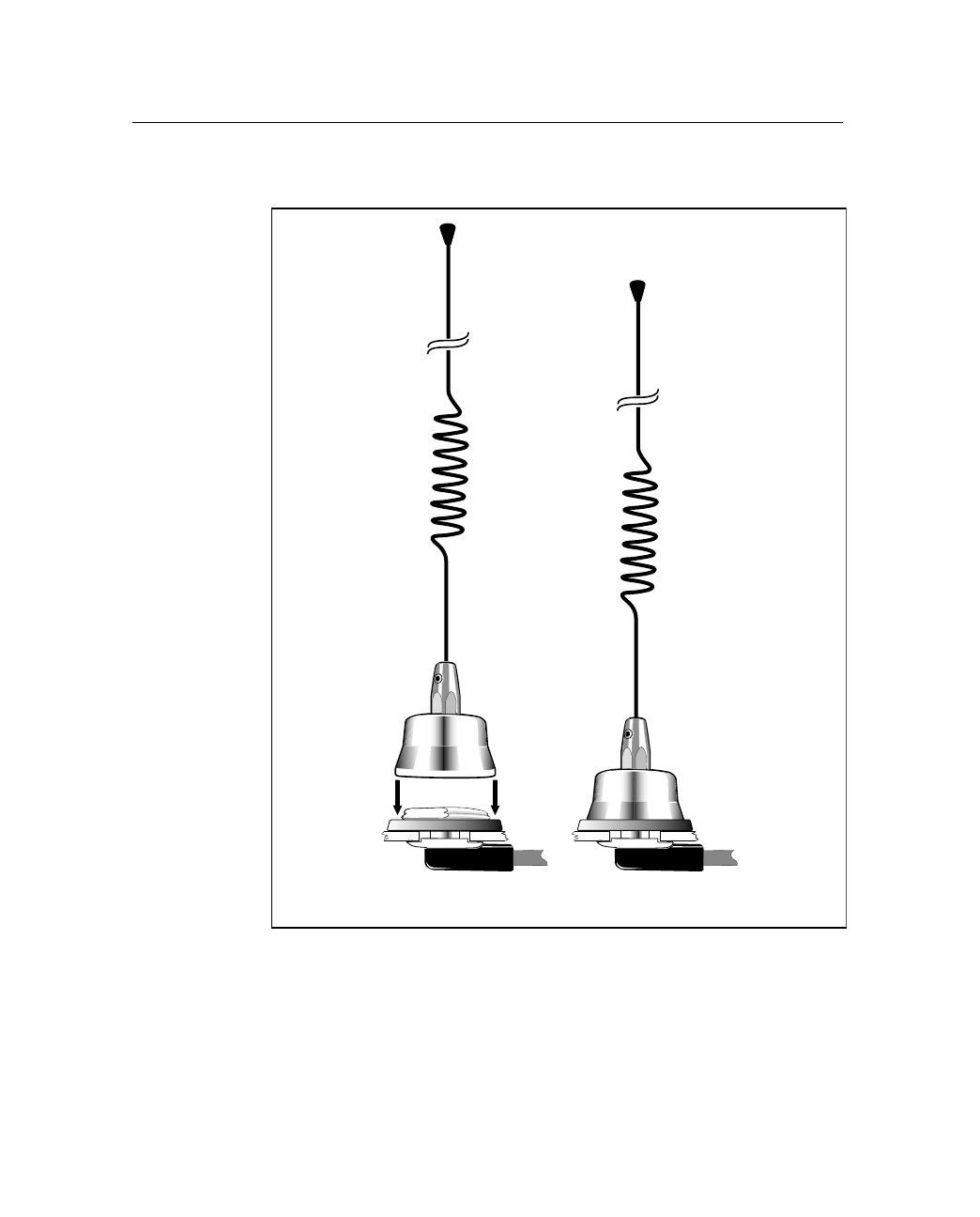
2.9.1 Magnetic Cellular Antenna (P/N 46721)
The Magnetic-Mount Cellular antenna and Magnetic Base (see
Figure 2.13) is designed for temporary mounting on any ferrous
surface.
Figure 2.13 Magnetic Cellular Antenna
The antenna features a 3.5 m (11.5 ft.) integral coaxial cable
terminated with a TNC-M connector, which is compatible with the
CrossCheck CDPD’s Cellular Antenna connector. The antenna’s
magnetic base adheres to any ferrous surface and requires no fasteners
or mounting hardware.
Magnetic Base
Magnetic Mount
Cellular Antenna
2 Installation
34 CrossCheck CDPD Mobile Unit Manual
To mount the Magnetic-Mount Cellular Antenna:
1. Mount the antenna to a ferrous surface, following the
instructions provided with the antenna.
2. Route the antenna cable. For detailed cable routing guidelines,
see Routing the Cellular Antenna Cable on page 2-38.
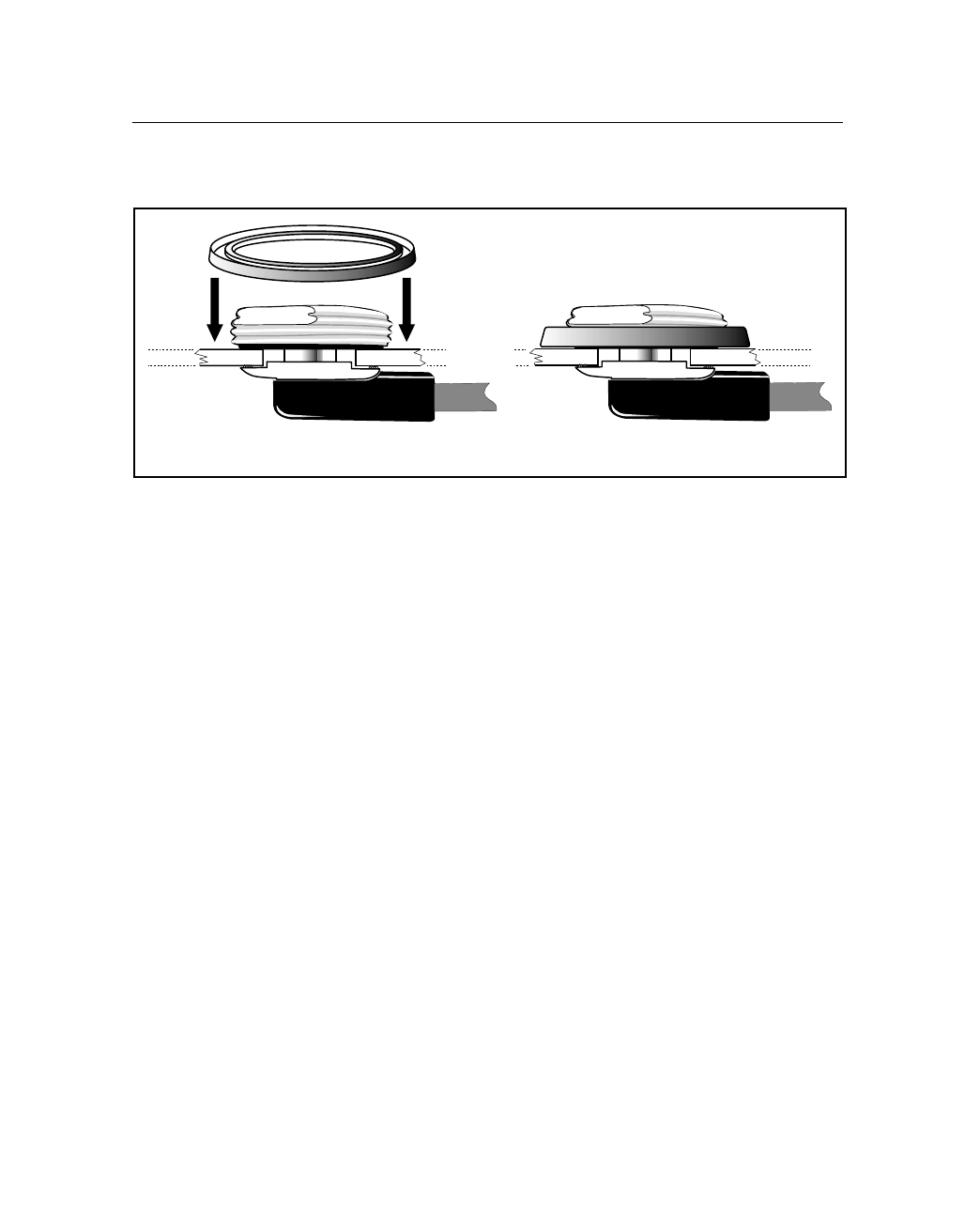
2.9.2 Bulkhead Cellular Antenna (P/N 46730)
The Bulkhead Cellular antenna is designed to be permanently
mounted on the vehicle.
To install the antenna:
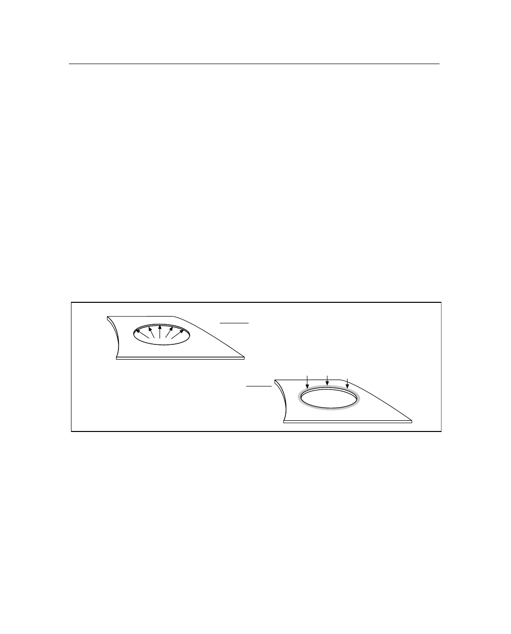
1. Drill a 19 mm (0.75 in) hole through the vehicle’s metal
surface, and carefully use a deburring tool to remove burrs from
the interior and exterior of the hole (see Figure 2.14).
Figure 2.14 Burr Removal and O-Ring Seal Surface Inspection
Note – Use care to avoid scratching the top surface of the hole. The
o-ring on the cable mounting assembly must seal to the top surface of
the vehicle’s sheet metal. Scratches may prevent the o-ring from
sealing properly and could result in water leakage.
2. Carefully remove the brass nut on the antenna cable mounting
assembly, using care to avoid damaging the o-ring in the lower
surface of the brass nut.
Use a deburrin
g
tool to remove all
burrs from the interior and exterior
of hole.
Assure that the o-rin
g
seatin
g
surface is free of scratches.
CrossCheck CDPD Mobile Unit Manual 35
Installation 2
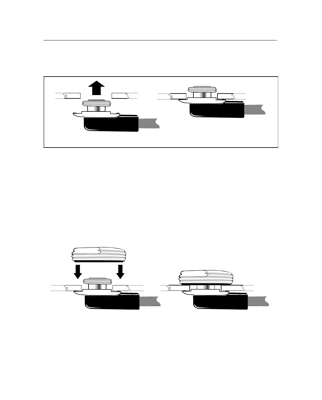
3. Position the cable mounting assembly below the 19 mm
(0.75 in.) hole from the interior of the vehicle (see Figure 2.15).
Figure 2.15 Mounting the Antenna Cable Assembly
Two people may be required to perform this operation,
depending on the vehicle location where the antenna is
mounted.
4. Re-install the brass nut from the exterior of the vehicle (see
Figure 2.16). Turn the brass nut until the cable mounting
assembly is secured in place. The brass nut must make metal-to-
metal contact with the vehicle's sheet metal to allow the o-ring
to seal properly.
Figure 2.16 Re-installing the Brass Nut
12
34
2 Installation
36 CrossCheck CDPD Mobile Unit Manual
5. Place the rubber gasket over the brass nut (see Figure 2.17).
Figure 2.17 Attaching the Antenna to the Cable Assembly
6. Carefully thread the antenna mount onto the brass nut
protruding through the top of the sheet metal. Continue to turn
the antenna mount until the rubber gasket firmly seats against
the vehicle's sheet metal surface.
56

2 Installation
38 CrossCheck CDPD Mobile Unit Manual
8. Cut the antenna cable to remove any extra slack, and install the
TNC connector on the cable end, following the manufacturer’s
recommendations.
2.9.3 Routing the Cellular Antenna Cable
The Magnetic Cellular antenna has an integral antenna cable with a
TNC-M connector. The Bulkhead Cellular antenna has a 5-m (16 ft.)
integral antenna cable, which is terminated within the FME connector.
After routing the Bulkhead Cellular cable, the cable must be fitted
with a TNC (plug) connector, before attaching the cable to the
CrossCheck CDPD. Instructions for installing the TNC connector are
included with the antenna kit.
The next step in the installation process is routing and connecting the
antenna cable to the CrossCheck CDPD. When routing the cable, start
at the antenna and choose the most direct path to the
CrossCheck CDPD while avoiding the following hazards:
•Excess coils in the antenna cable, particularly the cellular
antenna cable. A coiled cable can act as an antenna and may
receive interference.
•Pinching the cable in a hinged door. Provide an adequate service
loop when routing the cable around vehicle hinges.
•Vehicle movement that might cause cable damage. Make sure
that the coax cable is not routed through areas where vehicle
movement can abrade the cable surface.
•Exposure to environmental damage. If your cellular antenna
cable is exposed to the environment, use tie wraps to secure the
cellular antenna cable along its route to prevent wind damage.
The Magnetic Cellular antenna cable is exposed to the
environment. Since the wind could cause the cable to whip
around, tie wraps should be used to secure the cable along
its route.

CrossCheck CDPD Mobile Unit Manual 39
Installation 2
2.9.4 Connecting the Magnetic Cellular Antenna Cable
After routing the Magnetic Cellular Antenna cable, connect the cable
to the TNC connector labeled Cellular on the front panel. Tighten the
connector firmly to prevent loosening caused by normal vehicle
vibration.
2.9.5 Connecting the Permanent-Mount Cellular Cable
Once the cable routing is complete and the cable is secured attach the
TNC connector on the antenna cable. Then attach the cable to the
connector labeled Cellular on the front panel of the
CrossCheck CDPD.
2 Installation
40 CrossCheck CDPD Mobile Unit Manual
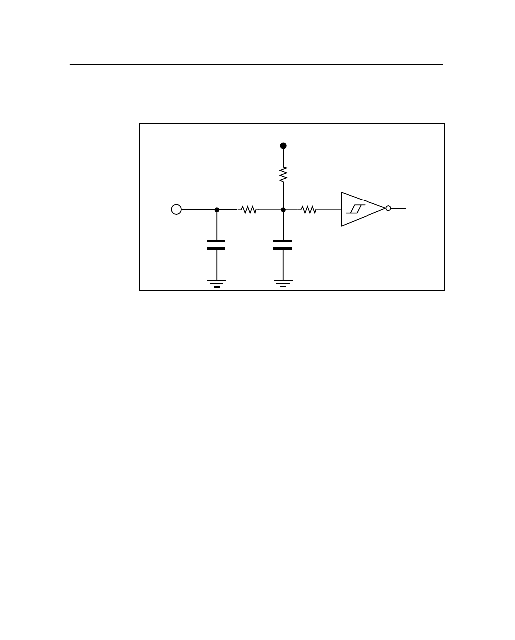
2.9.6 Inputs (IP0 to IP3)
The CrossCheck CDPD supports four discrete inputs. The circuit
diagram is shown in Figure 2.19.
Figure 2.19 Input Circuit Diagram
Each input floats to a logic-high state (inactive) when left open.
Grounding an input causes a logic-low state (active). The
CrossCheck CDPD can be configured to detect either logic-high or
logic-low states at the inputs whenever the unit is powered on.
Note – When the CrossCheck CDPD is powered off or in Power
Management mode, it can only detect a logic-low (grounded) input.
The discrete inputs are compatible with properly connected relays and
switches or with standard 3.3 VDC logic levels. A properly connected
relay or switch allows the input to float high in one position and
grounds the input in the other position.
Input Logic High: Open circuit or Vin > 2.4 VDC
Input Logic Low: Vin < 0.6 VDC
The inputs must remain in either state for at least
200 milliseconds before the CrossCheck CDPD
detects the input.
Input Current (Max) Iin < 3 mA
1 mA is typical at 12 VDC.
Input Protection: Protected up to at least VBatt continuous
3K
330K
0.1µF
To logic
470pf
Input 100K
3.3V/10m/A
CrossCheck CDPD Mobile Unit Manual 41
Installation 2
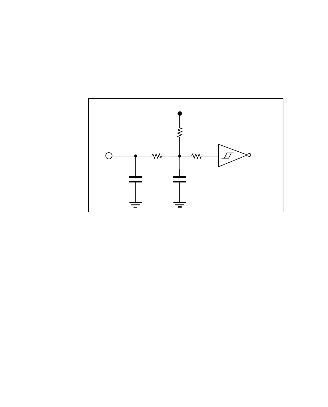
2.9.7 Pulse Counting Inputs (Pulse 0 to Pulse 2)
The CrossCheck CDPD also supports three pulse-counting inputs that
can be used in several applications. The circuit diagram is shown in
Figure 2.19.
Figure 2.20 Pulse Countin Input Circuit Diagram
Input Logic High: Open circuit or Vin > 2.4 VDC
Input Logic Low: Vin < 0.6 VDC
The inputs must remain in either state for at least
200 milliseconds before the CrossCheck CDPD
detects the input.
Input Current
(Max) Iin < 3 mA
1 mA is typical at 12 VDC.
Minimum Pulse
Width 500 microseconds
Input Protection: Protected up to at least VBatt continuous
3K
330K
0.01µF
To logic
470pf
Input 100K
3.3V/0.5/A
2 Installation
42 CrossCheck CDPD Mobile Unit Manual
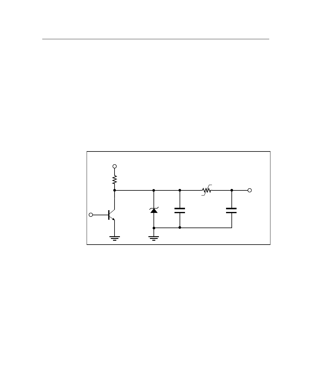
2.9.8 Outputs (XP0 to XP2)
The CrossCheck CDPD features three discrete outputs (XP0–XP2) for
driving external devices such as relays.
•When inactive (use state), the discrete outputs are tied to vehicle
battery voltage (nominally 12 VDC) through a 15 kOhm
resistor.
•When active, the outputs are shorted to ground through a
bipolar junction transistor. In the active (low) state, the outputs
can sink up to 200 mA.
Figure 2.21 shows a diagram of a discrete output.
Figure 2.21 Output Circuit Diagram
Output Inactive: 15 kOhms through Vvehicle-battery
Output Active: Tied to ground through a saturated bipolar
junction transistor, Vout 1.5 VDC at
200 mA; Vout < 0.5 VDC at
10 mA
Output Protection: Protected against direct shorts to ground
Output Sink Current
Capability Up to 200 mA
15K
36V 0.01µF
0.2A
470pf
Output
Vbatt
CrossCheck CDPD Mobile Unit Manual 43
Installation 2
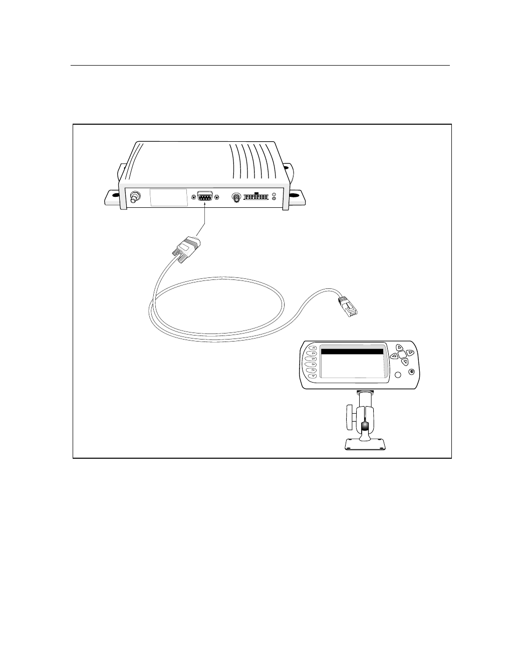
Figure 2.22 shows the cable connections between a PC and the
CrossCheck CDPD.
Figure 2.22 PC to CrossCheck CDPD Connections
Warning: All persons must
be at least 20 cm from
antenna when transmitter
operating to meet FCC RF
exposure requirements.
CrossCheck CDPD
Echo
LDX
Power/Data Cable
Echo
LDX
RJ45 Connector
MDT Port
To Serial Port 2 on
Echo
LDX

2 Installation
44 CrossCheck CDPD Mobile Unit Manual
2.10 CrossCheck CDPD Power
The CrossCheck CDPD operates on input voltages from 9–32 VDC.
The low-noise amplifier integrated on the GPS antenna draws power
from the CrossCheck CDPD through the antenna cable. The
CrossCheck CDPD does not require any special power-up or down
sequencing.
The CrossCheck CDPD’s power circuitry is designed to protect the
unit from random power fluctuations and conditions. Input circuits
protect against transient voltage spikes found in most auto and truck
environments. An external fuse protects against excessive current.
For more information on the CrossCheck CDPD power requirements,
see Appendix A.
CrossCheck CDPD Mobile Unit Manual 45
Installation 2
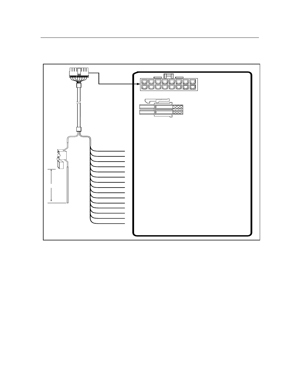
Figure 2.23 illustrates the power and I/O cable.
Figure 2.23 Power and I/O Cable (P/N 46598-00)
Note – Trimble recommends installing the power and ground leads as
close to the battery as possible to ensure that the CrossCheck CDPD is
connected to the cleanest possible source of power.
1 Vbat Red Input Power 9-32V
2 GND Black
3 GND Green Chassis GND
4 GND Blk/White GND
5 White Ignition Sense Input
6 Blue Input 3
7 Purple Input 2
8 Orange Discrete Output 2
9IP1 Input 1
10 Gray Discrete Output 1
1 1 Purple/White Input 0
12 Brown Discrete Output 0
468
10 12
1
2
3579
11
14 16
Connector
Molex Micro-Fit 3.0 16-Pin
Molex P/N 43025-1600
Pins
Molex Female
templated Contact
Molex P/N 43030-0001
Side View
Yellow
XP1
IP0
XP0
IGN
IP3
IP2
XP2
13 Pulse 0 Brn/White Pulse Counter Input 0
14 Pulse 1 Gray/White Pulse Counter Input 1
15 Pulse 2 Orange/White Pulse Counter Input 2
16 8V AUX Red/White 8 VDC Auxiliary Input
Batt.GND
Pulse 0
Pulse 1
Pulse 2
8V Aux
Batt. GND
Chassis GND
GND
IGN
IP3
IP2
XP2
IP1
XP1
IP0
XP0
VBatt.
2A @ 250V
Blade Type
156"
13 15
Front View

2 Installation
46 CrossCheck CDPD Mobile Unit Manual
The CrossCheck CDPD is protected against both input power over-
voltage and reverse polarity. The primary power cable has a built-in
fuse. The DC ground line connects to the vehicle’s DC ground. The
ignition-sense lead, if connected to a source of ignition-switched
battery voltage, senses when the vehicle’s ignition is active. There are
three connection options for connecting the power, ground, and
ignition-sense wires. These options are described in the next three
sections.
2.10.1 Connections For Power Management
The CrossCheck CDPD operates continuously only when the vehicle
is running. When the ignition is off, the CrossCheck CDPD goes to
sleep, drawing reduced power. For more information on current draw
in different operation modes, see Appendix A.
The default Power Management configuration for the
CrossCheck CDPD is the following:
•When the ignition is OFF, the unit goes to sleep state after
3 minutes.
•If the EchoLDX is connected to the CrossCheck, the EchoLDX
will turn off 1 minute after ignition OFF is detected.
CrossCheck CDPD Mobile Unit Manual 47
Installation 2
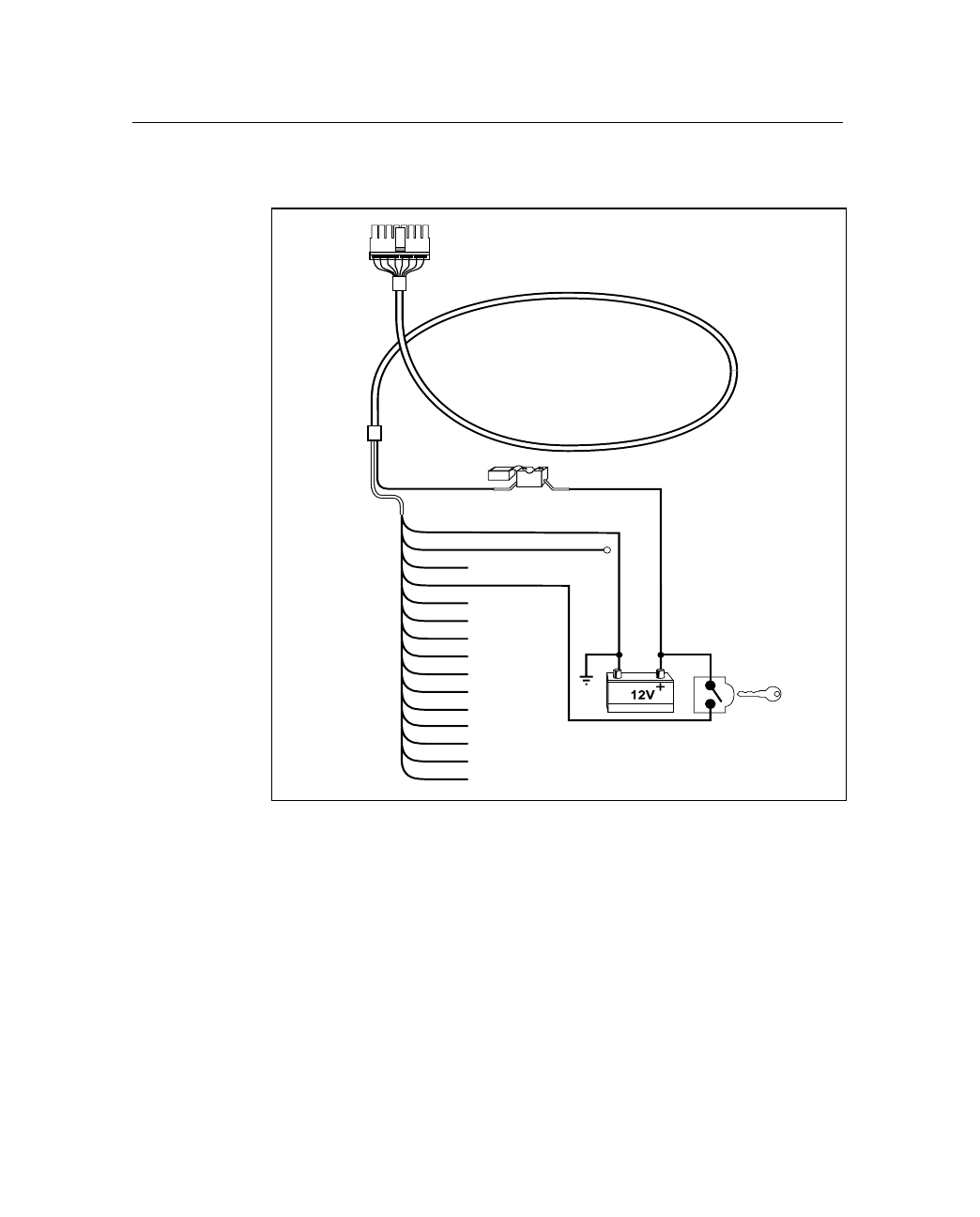
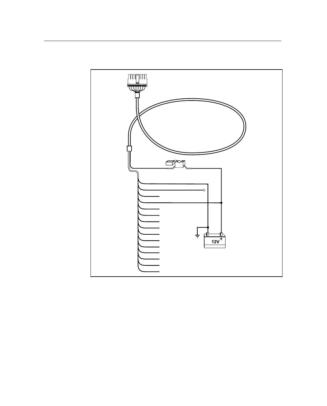
Figure 2.24 illustrates the Power Management connections.
Figure 2.24 Power Management Connections
To install the power cable for use with the Power Management feature:
1. Connect the primary power line to a nonswitched/continuous
source of DC power, such as the vehicle’s battery.
2. Connect the ignition-sense line to ignition-switched battery
power so that this line is active when the ignition is on.
Power and I/O Cable
Vbatt.
Batt. GND
Chassis GND
GND
IGN
IP3
IP2
XP2
IP1
XP1
IP0
XP0
Pulse 0
Pulse 1
Pulse 2
8V Aux
2A @ 250V
Blade Type
To CrossCheck
CDPD
Red
Black
Green
White

2 Installation
48 CrossCheck CDPD Mobile Unit Manual
2.10.2 Continuous Power Connection (No Power Management)
For the Continuous Power configuration (see Figure 2.25), the
CrossCheck CDPD operates and draws power continuously, even
when the vehicle is not running:
•Idle mode (not transmitting) without the EchoLDX Message
Terminal, 130 mA is typical @ 12 VDC
•Idle mode (not transmitting) with the EchoLDX Message
Terminal, 200 mA is typical @ 12 VDC
,Caution – With the Continuous Power Configuration, the
CrossCheck CDPD may drain a car battery in 1 to 3 weeks,
depending on the battery quality and remaining life span, and whether
or not the vehicle is operating during the entire time. Observe
extreme care when using this connection option. The
CrossCheck CDPD will automatically power off when the voltage
drops below 9 VDC.
CrossCheck CDPD Mobile Unit Manual 49
Installation 2
Figure 2.25 illustrates connections for Continuous Power.
Figure 2.25 Continuous Power Connections
To connect the power cable to Continuous Power:
1. Connect the primary power line.
2. Connect the ignition-sense line to a nonswitched/continuous
source of DC power, such as the vehicle’s battery.
Power and I/O Cable
Vbatt.
Batt. GND
Chassis GND
GND
IGN
IP3
IP2
XP2
IP1
XP1
IP0
XP0
Pulse 0
Pulse 1
Pulse 2
8V Aux
2A @ 250V
Blade Type
To CrossCheck
CDPD
Red
Black
Green
White

2 Installation
50 CrossCheck CDPD Mobile Unit Manual
2.11
Installing the Echo
LDX
Kit
The EchoLDX Message Terminal can be installed in almost any type
of vehicle. There are four steps in this procedure:
1. Assemble the mounting pedestal.
2. Mount the EchoLDX.
3. Route the Power/Data cable.
4. Connect the Power/Data cable to the CrossCheck CDPD.
This section provides detailed installation instructions.
2.11.1 Configuration Parameters
In addition to the physical installation of the unit, configuration
parameters can be set in each unit. Trimble recommends that if a
configuration other than the factory setting is used, every unit in the
fleet be given the same settings so that operation is consistent from
vehicle to vehicle. EchoLDX configuration is discussed in the
EchoLDX Message Terminal for CrossCheck CDPS and CrossCheck
GPRS Installation and User’s Manual, Trimble Part Number 46667-
00-ENG.
2.11.2 Preparing for Installation
Inventory
Prior to installation, confirm that you have received the required
EchoLDX components:
•EchoLDX Message Terminal
•Power/Data cable
•EchoLDX mounting pedestal kit (6") and mounting hardware
•EchoLDX Quick Reference Guide

CrossCheck CDPD Mobile Unit Manual 51
Installation 2
2.11.3 Choosing a Location
Choose a location for the EchoLDX where the display is easy to view
and the keypad is readily accessible. When selecting a location, avoid
exposure to extreme environmental conditions, including:
•Excessive heat or cold
•High vibration
•Corrosive fluids and gases
•Wet or damp locations
Avoiding these conditions will improve the EchoLDX's performance
and will ensure long-term reliability.
All standard external connections to the EchoLDX are made through
the connector (marked as 2) on the bottom of the unit.
2.11.4 Mounting the Pedestal and Installing the Echo
LDX
The EchoLDX can be attached to any flat surface using the mounting
assembly. When positioning the assembly on the mounting surface,
allow sufficient clearance beneath the EchoLDX for the Power/Data
cable and on the right side of the unit for the maintenance and
upgrade cable.
To mount the pedestal:
1. In the vehicle, select a mounting surface for the pedestal and
temporarily place the MDT at the top on the pedestal. Ensure
that the MDT is accessible by all possible operators.
2. Verify that there is clearance behind the mounting surface for
the mounting screws. Choose the appropriate screws to install
the pedestal to the mounting surface—either sheet metal screws
or machine screws with lock nuts.
3. Remove the MDT from the top of the pedestal.
2 Installation
52 CrossCheck CDPD Mobile Unit Manual
4. Place the pedestal base on the mounting surface and secure it
with the appropriate screws.
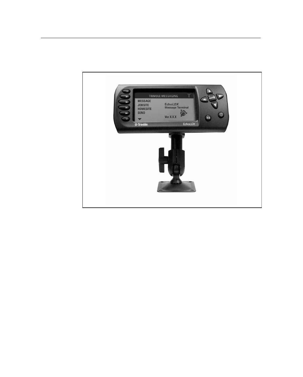
Figure 2.26 Echo
LDX
Attached to Mounting Assembly
5. Affix the MDT to the mounting pedestal. Position the MDT and
tighten all locking nuts.
2.11.5 Routing the Power/Data Cable
The next step in the installation process is to route the Power/Data
cable from the EchoLDX to the CrossCheck. When routing the cable,
avoid the following hazards:
•Sharp bends or kinks in the cable
•Hot surfaces (exhaust manifolds or stacks)
•Rotating or reciprocating equipment
CrossCheck CDPD Mobile Unit Manual 53
Installation 2
•Sharp or abrasive surfaces
•Door and window jambs
•Corrosive fluids or gases
Follow these installation guidelines:
•Choose the most direct path to the destination.
•Leave enough excess cable for a service loop, to allow for
removal of the EchoLDX and the CrossCheck.
•Secure the cable to the pedestal with a cable tie.
Power and Interface Connections
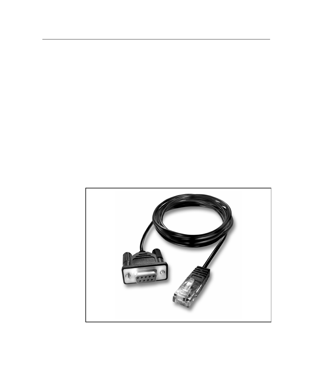
The 2.90 m Power/Data cable provided with the EchoLDX includes a
RJ-45 connector at one end and a serial connection and a DB9M at the
other (as shown in Figure 2.27).
Figure 2.27 Echo
LDX
Power/Data Cable
2 Installation
54 CrossCheck CDPD Mobile Unit Manual
The cable connects to the CrossCheck through the DB9F connector
labeled MDT. Power is supplied to the EchoLDX through the same
data cable.
Note – When the cable connection is complete, secure the cable using
a cable tie.
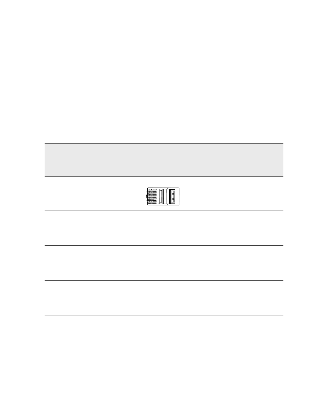
Table 3.1 describes the pin locations for the EchoLDX connector and
the Power/Data cable, as viewed from the front of the connector.
Table 2.4 Echo
LDX
Power/Data Cable Pinout Connections
CrossCheck
MDT Port
DB9
Pin Number
Echo
LDX
Power/Data
Cable Wire Color
Echo
LDX
Cable
RJ-45 Connector
Pin Number Si
g
nal Name
2 Green with white
stripe wire 5 RxD, Input to MDT
3 White with Brown
stripe wire 4 TxD, Output to MDT
5 Gray with white
stripe wire 1 Ground
7 Brown with white
stripe wire 3RTS
(Handshake output from MDT)
8 White with green
stripe wire 6CTS
(Handshake input to MDT)
9 White with Grey
stripe wire 2Power
8
1


3 Operation
56 CrossCheck CDPD Mobile Unit Manual
3.1 Introduction
Once you have installed and configured the CrossCheck CDPD, it is
ready for operation. When power is applied, the CrossCheck CDPD
operates automatically without user intervention, based on its
firmware configuration.
This chapter provides a basic overview of the CrossCheck CDPD’s
operation, including:
•LED Indicators
•GPS Receiver
•CDPD Transceiver
3.2 LED Indicators
The CrossCheck CDPD includes two LED indicators: GPS and GSM.
The firmware:
•Continuously monitors the GPS receiver and the
CrossCheck CDPD phone operation
•Controls the two LED indicators
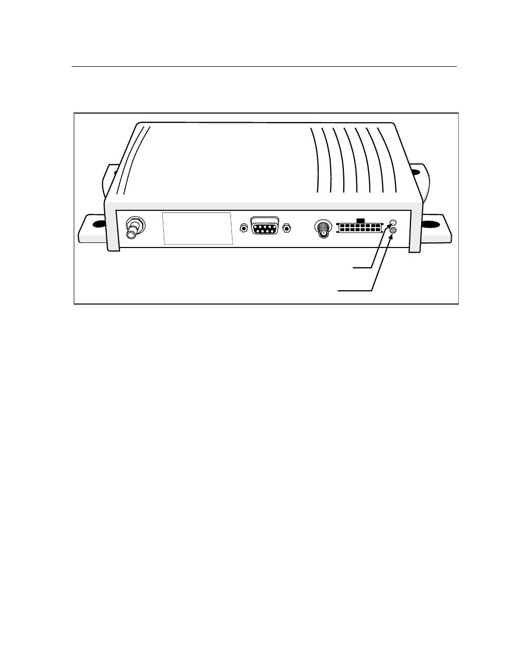
CrossCheck CDPD Mobile Unit Manual 57
Operation 3
Figure 3.1 shows the CrossCheck CDPD LED indicators.
Figure 3.1 CrossCheck CDPD LED Indicators
3.2.1 LED States
The GPS and CDPD LED have three states: On, Off, and Blink.
When both LED indicators are off, the CrossCheck CDPD’s power is
off. When one or more LED indicators are on or blinking, the power
is on.
3.2.2 LED Power-On Sequence
When the CrossCheck CDPD’s ignition input and power inputs are
activated:
•The LEDs blink once.
•Both turn off for approximately 5 seconds.
•Both remain on for approximately 2 seconds.
Warning: All persons must
be at least 20 cm from
antenna when transmitter
operating to meet FCC RF
exposure requirements.
GPS LED (Green)
CDPD LED (Amber)

3 Operation
58 CrossCheck CDPD Mobile Unit Manual
The GPS LED is on for approximately 2 seconds, then blinks until the
first position fix is computed. During this period, the CDPD LED
blinks until the unit is established in a CDPD area, at which point the
CDPD LED turns off. When a call is active, the CDPD LED stays on
for the duration of the call.
3.2.3 GPS and CDPD LED States
Table 3.1 identifies the GPS LED states.
Table 3.2 identifies the GSM LED states.
Table 3.1 GPS LED States (Green LED)
GPS LED State Meaning
On Computing GPS position fixes.
Blink Not computing GPS position fixes.
Off No power is available, or CrossCheck CDPD is in Sleep mode.
Table 3.2 GSM LED States (Amber LED - when GPS green LED is on or flashing)
CDPD LED State Meaning
On Data call in progress.
Slow Blink No CDPD coverage is available; the CrossCheck CDPD is not registered
with network.
Off CDPD coverage is available; no call in progress.

CrossCheck CDPD Mobile Unit Manual 59
Operation 3
3.3 GPS Receiver Operation
At power-up, the GPS receiver initializes with the last-known position.
Using this information, the GPS receiver acquires satellite signals.
•During the satellite acquisition process—which normally
requires less than 2 minutes—the green GPS LED blinks.
•Once three or more satellites are acquired, the GPS receiver
computes positions, course, speed and time fixes, and the GPS
LED remains on.
A blinking GPS LED indicates that the GPS receiver is not tracking
enough satellites to calculate a current position. This occurs
occasionally when the vehicle is obscured from satellite signals by
terrain, buildings, trees, tunnels or other structures. During this
period—called satellite reacquisition—the GPS receiver continuously
searches for the obscured satellites and expands its search to other
satellites to continue position computations. For brief blockages, the
GPS receiver normally reacquires a lost satellite signal and resumes
position fixes in less than 2 seconds.

3 Operation
60 CrossCheck CDPD Mobile Unit Manual


A Specifications
62 CrossCheck CDPD Mobile Unit Manual
A.1 Introduction
This appendix lists the CrossCheck CDPD Mobile Unit and antenna
specifications.
A.2 Standard Components
The tables include general specifications and requirements for the
following:
• General Specifications, Table A.1
• Firmware Specifications, Table A.2
• GPS Specifications, Table A.3
• GPS Antenna Requirements, Table A.4
• CDPD Cellular Specifications, Table A.5
• Cellular Antenna Requirements, Table A.6
• CrossCheck CDPD Mobile Unit Physical Specifications,
Table A.7
• CrossCheck CDPD Mobile Unit P/N 46707-00, Table A.8
• Miniature Bulkhead GPS Antenna with Flange (P/N 31192-00),
Table A.9
• Miniature Bulkhead GPS Antenna without Flange (P/N 32434),
Table A.10
• Miniature Magnetic GPS Antenna (P/N 37167), Table A.11
• MDT Port, Table A.12
• Discrete Inputs: IP0 to IP3, Table A.13
• Pulse Counter Inputs, Table A.14
• Discrete Outputs: XP0 to XP2, Table A.15
• Component Part Numbers, Table A.16

CrossCheck CDPD Mobile Unit Manual 63
Specifications A
Table A.1 General Specifications
Item Specification
Power Requirements Transmitting - without Mobile Data Terminal: Typical 450 mA
(1.5 A peak) at 12 V (Transmitter at max power level)
Transmitting - with Mobile Data Terminal: Typical 520 mA
(1.6 A peak) at 12 V (Transmitter at max power level)
Idle (not transmitting) - without Mobile Data Terminal: Typical
130 mA at 12 V
Idle (not transmitting) - with Mobile Data Terminal: Typical
200 mA at 12 V
Sleepmode (all functions off, IGN sense and inputs active):
< 10 mA at12 V
MDT Port (1) RS-232 DCE
Serial Port Speed (bps) 9600
Data Rate over the Air 19,200 bps maximum
Discrete I/O Ports Discrete Inputs: (4) switch closures; ignition
Pulse Counting Inputs (3) minimum pulse width:
500 microseconds
Outputs: (3) 200 mA low-side drivers, Auxiliary output for
sensors: 100 mA max at 8.5 ±0.5 V
Status LEDs GPS (green) and CDPD (amber)

A Specifications
64 CrossCheck CDPD Mobile Unit Manual
Table A.2 Firmware Specifications
Item Specification
Event Handlers Geo-fence area for Job Sites
Geo-fence area for Home Sites
Entry Speed Limit for Site Dispatch purposes
Exit Speed Limit for Site Dispatch purposes
Site dispatch time-out
Minimum duration time to detect entry/exit regions
Support datalogging that allows the CrossCheck CDPD to
store messages and events for up to 1 week while out of the
network when outside CDPD coverage.
Automatic status reporting for ready mix applications.
Messaging Available through the Echo
LDX
terminal
Ignition Sense Off: V < 0.8 VDC; On: V > 2.4 VDC
Table A.3 GPS Specifications
Item Specification
Receiver L1 frequency, C/A code (SPS), 8-channel continuous tracking
receiver using the Trimble FirstGPS™ and Colossus™
technology
Update Rate Once per second maximum
Accuracy Position: better than10 meters (50% CEP)
Velocity: < 0.5 meter/second
Time to First Fix Cold start: < 180 seconds 90% of cases
Warm start: < 45 seconds 90% of cases
Hot start: < 20 seconds 90% of cases
Reacquisition after 15-second blockage: < 2 seconds 90%
of cases
Datum WGS-84

CrossCheck CDPD Mobile Unit Manual 65
Specifications A
Table A.4 GPS Antenna Requirements
Item Specification
Antenna Impedance 50 Ω
Antenna RF Gain 20 dBi minimum gain, measured at the input connector to the
CrossCheck CDPD
Noise Figure 2.5 dB maximum, measured at the input connector to the
CrossCheck CDPD
VSWR 2:1 Max over range
Power 5.0 ±0.5 VDC @ 40 mA maximum on center conductor
Table A.5 CDPD Cellular Specifications
Item Specification
Cellular CDPD Specification 1.0 and 1.1, 600 mW Full Duplex
Frequencies Transmit: 824 to 849 MHz
Receive: 869 to 894 MHz
Receiver Sensitivity –111 dBm
Type Approvals FCC Part 15 Class B and Part 22 (from OEM module)
FCC ID = JUPCCKCDPD
Industry Canada

A Specifications
66 CrossCheck CDPD Mobile Unit Manual
Warning – To meet FCC RF exposure requirements, the maximum gain
for externally mounted antennas (plus any cable losses) cannot be more
than 3 dBi.
Warning – To meet FCC RF exposure requirements, all persons must be
at least 20 cm from the CDPD antenna when the transmitter is operating.
Table A.6 Cellular Antenna Requirements
Item Specification
Antenna Impedance 50 Ω
Maximum Antenna Gain Externally mounted antenna gain plus cable loss should total
no more than 3 dBi gain to comply with FCC limits.
VSWR 1.5:1 nominal, 2.0:1 maximum
Table A.7 CrossCheck CDPD Mobile Unit Physical Specifications
Item Specification
Assembly Bottom: Aluminum
Top: Injection-molder plastic with integrated shield
Size 228 mm W x 121 mm D x 28 mm H
(9.6” W x 4.75” D x 1.9” H)
Weight 450 g (1 lb.)
Connectors MDT: DB9 (receptacle)
Power/Ignition + Digital I/O: Molex Micro-Fit 3.0 16-pin 2-row
locking (receptacle)
GPS antenna: SMA (receptacle) 50 Ω
CDPD antenna: TNC (receptacle) 50 Ω

CrossCheck CDPD Mobile Unit Manual 67
Specifications A
A.3 Environmental Specifications
The tables in this section list the environmental specifications for the
for following:
•CrossCheck CDPD Mobile Unit P/N 46707-00
•Miniature Bulkhead GPS Antenna with Flange (P/N 31192-00)
•Miniature Bulkhead GPS Antenna without Flange (P/N 32434)
•Miniature Magnetic GPS Antenna (P/N 37167)
Table A.8 CrossCheck CDPD Mobile Unit P/N 46707-00
Item Specification
Operating Temperature –20°C to +60°C
Storage Temperature –40°C to +85°C
Humidity 5% to 95% RH, non-condensing at +40°C
Altitude Range –1000 to +18,000 meters
Velocity Range 0 to 515 meters/second (999 miles/hour)
Vibration 0.008g2/Hz 5 Hz
+3dB/Octave 5 Hz to 20 Hz
0.05g2/Hz 20 Hz to 100 Hz
–3dB/Octave 100 Hz to 800 Hz
0.001g2/Hz 800 Hz to 1000 Hz
Shock Operational: 40 g for 11 milliseconds
Non operational: 75 g for 6 milliseconds
Vehicle Transient Noise ETS 300 342-1, Section 9-5

A Specifications
68 CrossCheck CDPD Mobile Unit Manual
Table A.9 Miniature Bulkhead GPS Antenna with Flange (P/N 31192-00)
Item Specification
Size 62.6 mm D x 19.0 mm H (3.5" D x 0.75" H)
Weight 0.13 kg (4.59 ounces)
Mounting Hole Circle 762 mm (3.0 in.), 4 holes, 0.6 mm (0.15 in.)
Center Mounting Hole 63 mm (0.75 in.)
Threaded Nut 63 mm TNC (0.75 in.)
Operating Temperature –40°C to +85°C
Storage Temperature –55°C to +85°C
Humidity 5% to 95% RH, non-condensing at +40°C
Casing Dustproof, waterproof, shock-resistant polycarbonate
Minimum Gain 28 dBi
Maximum Allowable Cable Loss 8 dB
Table A.10 Miniature Bulkhead GPS Antenna without Flange (P/N 32434)
Item Specification
Size 62.6 mm D x 19.0 mm H (3.5" D x 0.75" H)
Weight 0.13 kg (4.59 ounces)
Mounting Hole Circle 762 mm (3.0 in.), 4 holes, 0.6 mm (0.15 in.)
Center Mounting Hole 63 mm (0.75 in.)
Threaded Nut 63 mm TNC (0.75 in.)
Operating Temperature –40°C to +85°C
Storage Temperature –55°C to +85°C
Humidity 5% to 95% RH, non-condensing at +40°C
CrossCheck CDPD Mobile Unit Manual 69
Specifications A
A.4 I/O Characteristics
Casing Dustproof, waterproof, shock-resistant polycarbonate
Minimum Gain 28 dBi
Maximum Allowable Cable Loss 8 dB
Table A.11 Miniature Magnetic GPS Antenna (P/N 37167)
Item Specification
Size 40.0 mm W x 47.0 mm D x 13.3 mm H
(1.515" W x 1.85" D x 0.524" H)
Weight Antenna and cable: 0.13 kg (4.59 ounces)
Antenna only: 0.045 kg (1.59 ounces)
Operating Temperature –40°C to +85°C
Storage Temperature –55°C to +85°C
Humidity 5% to 95% RH, non-condensing at +40°C
Casing Dustproof, waterproof, shock-resistant polycarbonate with
magnetic mount
Minimum Gain 26 dBi
Table A.12 MDT Port
Item Specification
Physical TXD, RXD, RTS, CTS, GND, DTR, DCD, DTS, 8.5 ±.5 V
provided through Pin 9
Baud Rates 9600, No parity, 8 bits, 1 stop bit
Table A.10 Miniature Bulkhead GPS Antenna without Flange (P/N 32434) (Continued)

A Specifications
70 CrossCheck CDPD Mobile Unit Manual
Table A.13 Discrete Inputs: IP0 to IP3
Item Specification
Input Logic High Open circuit or Vin > 2.4 VDC
Input Logic Low Vin < 0.6 VDC
The inputs must remain in either state for at least
500 milliseconds before the CrossCheck CDPD detects
the input.
Input Current Iin ± 3 mA
Input Protection Protected up to at least VBatt continuous
Table A.14 Pulse Counter Inputs
Item Specification
Input Logic High Open circuit or Vin > 2.4 VDC
Input Logic Low Vin < 0.6 VDC
Input Current Iin ±3 mA
Minimum Pulse Width 500 microseconds
Input Protection Protected up to at least VBatt continuous
Table A.15 Discrete Outputs: XP0 to XP2
Item Specification
Output Inactive 15 KΩ tied to Vvehicle-battery Vout depending on load
Output Active Tied to ground through a saturated bipolar junction
transistor, Vout < 1.5 VDC @ 200 mA;
Vout < 0.5 VDC @ 10 mA
Output Sink Current Capability Up to 200 mA
Output Protection Protected against shorts to ground

CrossCheck CDPD Mobile Unit Manual 71
Specifications A
A.5 Accessories (ordered separately)
The following accessories can be ordered separately:
•GPS antennas: Permanent or magnetic mount
•Combination power and digital I/O cable (10-packs)
•Optional EchoLDX Message Terminal Kit including:
–EchoLDX Mobile Data Terminal
–Power/Data Cable
–Pedestal Mount Kit (6”)
– EchoLDX Message Terminal for CrossCheck CDPD and
CrossCheck GPRS Installation and User’s Manual
(available online)
–Quick Reference Guide
A.6 CrossCheck CDPD Part Numbers
Part numbers for the CrossCheck CDPD, options, and accessories are
listed in Table A.16.
Table A.16 Component Part Numbers
Description Part No.
CrossCheck CDPD Starter Kit 46720-00
CrossCheck CDPD - Ten Pack 46720-10
Upgrade Kits
Echo
LDX
Message Terminal Kit 46722-00
Echo
LDX
Message Terminal Kit - Ten Pack 46722-10

A Specifications
72 CrossCheck CDPD Mobile Unit Manual
GPS Antenna and Cable Bundles
GPS Antenna bundle (flange, straight cable), Includes:
31192-00 Mini Bulkhead antenna, TNC-p, gasket, 5-hole flange
36107 Cable, straight, TNC-r to straight SMA-p, 5 meter
36697-00
GPS Antenna bundle (flange, right-angle cable), Includes:
31192-00 Mini Bulkhead antenna, TNC-p, gasket, 5-hole flange
36106 Cable, right angle, TNC-r to right angle SMA-p, 5 meter
36698-00
GPS Antenna bundle (no flange, straight cable), Includes:
32434 Mini Bulkhead antenna, TNC-p, gasket, no flange
36107 Cable, straight, TNC-r to straight SMA-p, 5 meter
36699-00
GPS Antenna bundle (no flange, right-angle cable), Includes:
32434 Mini Bulkhead antenna, TNC-p, gasket, no flange
36106 Cable, right angle, TNC-r to right angle SMA-p, 5 meter
36700-00
GPS Antennas and Cables - separate
Mini Bulkhead antenna, TNC-p, gasket, 5-hole flange 31192-00
Mini Bulkhead antenna, TNC-p, gasket, no flange 32434
Cable, right angle, TNC-r to straight SMA-p, 5 meter 36106
Cable, straight, TNC-r to straight SMA-p, 5 meter 36107
Right angle adapter, SMA-p to SMA-r 36200
Mini Magnetic antenna with 5-meter cable, SMA-p 37167
CDPD Cellular Antennas
CDPD magnetic mount antenna TNC-p with 3.5 m cable 46721
CDPD bulkhead antenna TNC-p with 5 m cable 46730
Cables and Accessories
Power and I/O Cable Ten Pack 46598-10
Echo
LDX
Power/Data Cable, 2.90 meter 46755
Pedestal Mounting Kit
Echo
LDX
Quick Reference Guide 46845-00-ENG
Table A.16 Component Part Numbers (Continued)
Description Part No.

CrossCheck CDPD Mobile Unit Manual 73
Specifications A
Documentation (free download of latest version from the Web site)
CrossCheck CDPD Mobile Unit Manual
(only in electronic PDF format) 46750-00-ENG
Echo
LDX Message Terminal for CrossCheck CDPD and CrossCheck GPRS
Installation and User’s Manual
(only in electronic PDF format) 46667-00-ENG.
Table A.16 Component Part Numbers (Continued)
Description Part No.

A Specifications
74 CrossCheck CDPD Mobile Unit Manual

Reader Comment Form
CrossCheck CDPD Mobile Unit Manual January 2002
P/N: 46750-00-ENG Revision: A
We appreciate your comments and suggestions for improving this publication.
I use the following Trimble product______________________________________________ ,
for__________________________________________________________________________
Please circle a response for each of the statements below:
1 = Strongly Agree 2 = Agree 3 = Neutral 4 = Disagree 5 = Strongly Disagree
The manual is well organized 12345
I can find the information I want. 12345
The information in the manual is accurate. 12345
I can easily understand the instructions. 12345
The manual contains enough examples. 12345
The examples are appropriate and helpful. 12345
The layout and format are attractive and useful. 12345
The illustrations are clear and helpful. 12345
The manual is: too long just right too short
Please answer the following questions:
Which sections do you use the most? ______________________________________________
What do you like best about the manual? ___________________________________________
____________________________________________________________________________
What do you like least about the manual? ___________________________________________
____________________________________________________________________________
Optional
Name _______________________________________________________________________
Company ____________________________________________________________________
Address______________________________________________________________________
____________________________________________________________________________
Telephone_____________________________Fax____________________________________
Please mail to Trimble Navigation Limited, 645 North Mary Avenue, P.O. Box 3642,
Sunnyvale, CA 94088-3642. Alternatively, email your comments and suggestions to
ReaderFeedback@trimble.com. All comments and suggestions become the property of
Trimble Navigation Limited.
