Trimble RC60X Remote Control Transmitter User Manual manual
Trimble Inc. Remote Control Transmitter manual
Trimble >
manual

1
TABLE OF CONTENTS
Introduction 2
FOR YOUR SAFETY 2
COMPONENTS 2
How to use the Laser System 3
Powering the Laser 3
RC603 Radio/IR Remote Control 3
Turning On/Off the RC603 3
LASER SETUP 4
Turning On/Off the Laser 4
Features and functions 4
Standard Features 5
X-Y-Z-grade entering mode 5
Using the Rotation mode 6
Using the Scan mode 6
Manual mode 6
Special MENU Features 7
Menu Functions (Radio controlled) 7
Menu Functions (IR controlled) 7
Automatic PlaneLok mode 8
Automatic Grade Match 8
Manual Grade Match 9
Automatic Axis Alignment 9
Manual Spot Search mode 10
Activating/Deactivating Standby mode 10
Start Reference Check 11
Centering the Rotor 11
Setting Menu 11
Info 11
Service menu 11
Special Features - Vertical Setup 12
Z-Axis Automatic Spot Align 12
Z-axis Automatic Spot Lok 13
Z-axis Automatic Spot Match 13
Line Scan 14
Beam Plunge 14
Setting menu details 14
Pairing 14
Pairing the transmitter with remote control 15
Pairing the transmitter with receiver 15
Mask mode 15
Grade Entry 16
Grade Display 16
Sensitivity 16
HI-alert selection 16
User Name 17
Set Password 17
Password On/Off 17
Radio RF-Channel) 17
CALIBRATION 18
Checking Calibration of the Y- and X-Axes 18
Checking Calibration of the Z-(vertical) Axis 18
Troubleshooting 19
SF601 Spot Finder User Guide 20
PROTECTING THE UNIT 23
CLEANING AND MAINTENANCE 23
PROTECTING THE ENVIRONMENT 23
WARRANTY 23
TECHNICAL DATA 24
GB
120432trimble_UL633_01_GB.indd 1 14.04.12 11:40
2
Introduction
Thank you for choosing one of the Spectra Precision Lasers from the Trimble family of precision lasers.
The universal laser is an easy-to-use tool that offers accurate horizontal, vertical and sloped laser reference
up to 1300 ft (400 m) away using a receiver. The plumb beam can be detected automatically and manually
using the additional SpotFinder
For Your Safety
For hazardless and safe operation, read all the user guide instructions.
LASER RADIATION
AVOID DIRECT EYE
EXPOSURE CLASS 3A/3R
LASER PODUCT
• Useofthisproductbypeopleotherthanthosetrainedonthisproductmayresultinexposuretohazardous
laser light.
• Donotremovewarninglabelsfromtheunit.
• TheUL633isClass3A/3R(<5mW,600...680nm).
• Neverlookintothelaserbeamordirectittotheeyesofotherpeople.
• Alwaysoperatetheunitinawaythatpreventsthebeamfromgettingintopeople‘seyes.
• Ifinitialserviceisrequired,whichresultsintheremovaloftheouterprotectivecover,removalmustonlybe
performed by factory-trained personnel.
Caution:Useofotherthanthedescribeduserandcalibrationtoolsorotherproceduresmayresult
inexposuretohazardouslaserlight.
Caution:UsingdifferentthandescribedattheUL633userguide,mayresultinunsafeoperation.
COMPONENTS
a Keypad/LCD-Display
b Handle
c Rotor with fan beam lens
d Sunshade
e Axes-Alignment-Marks
f Sighting Guides/Scope Mounts
g Battery door
h Rubber Cover/Recharge Jack
i 5/8” x 11 Tripod Mounts
j Rubber Feet
k Turnable Legs
l Plus and Minus Battery Diagrams
120432trimble_UL633_01_GB.indd 2 14.04.12 11:40
3
HOW TO USE THE LASER SYSTEM
POWERING THE LASER
Batteries
WARNING
Ni-MHbatteriesmaycontainsmallamountsofharmfulsubstances.Besuretochargethebattery
beforeusingitforthersttime,andafternotusingitforanextendedlengthoftime.Chargeonlywith
speciedchargersaccordingtodevicemanufacturer‘sinstructions.Donotopenthebattery,dispose
ofinreorshortcircuit;itmayignite,explode,leakorgethotcausingpersonalinjury.Disposein
accordance with all applicable federal, state, and local regulations. Keep the battery away from
children.Ifswallowed,donotinducevomiting.Seekmedicalattentionimmediately
Recharging the Batteries
ThelaserisshippedwitharechargeableNi-MHbatterypack.
Note: TheapproximatechargeofthebatteriesisshownatthelefttopsideoftheLCD.
Thechargerrequiresapprox.10hourstochargeemptyrechargeablebatteries.
Forcharging,connecttheplugofthechargertotherechargejackofthebatterypack.
Neworlong-timeout-of-userechargeablebatteriesreachtheirbestperformanceafter
beingchargedandrechargedvetimes.ForIndoorapplicationsthechargercanbe
usedasapowersupplyfortheUL.
Alkalinebatteriescanbeusedasabackup.Insert4D-cellbatteriesnotingtheplus
(+) and minus (-) diagrams inside the battery housing.
The batteries should only be charged when the laser is between 50° F and 104° F (10°C to
40°C). Charging at a higher temperature may damage the batteries. Charging at a lower
temperature may increase the charge time and decrease the charge capacity, resulting in
loss of performance and shortened life expectancy.
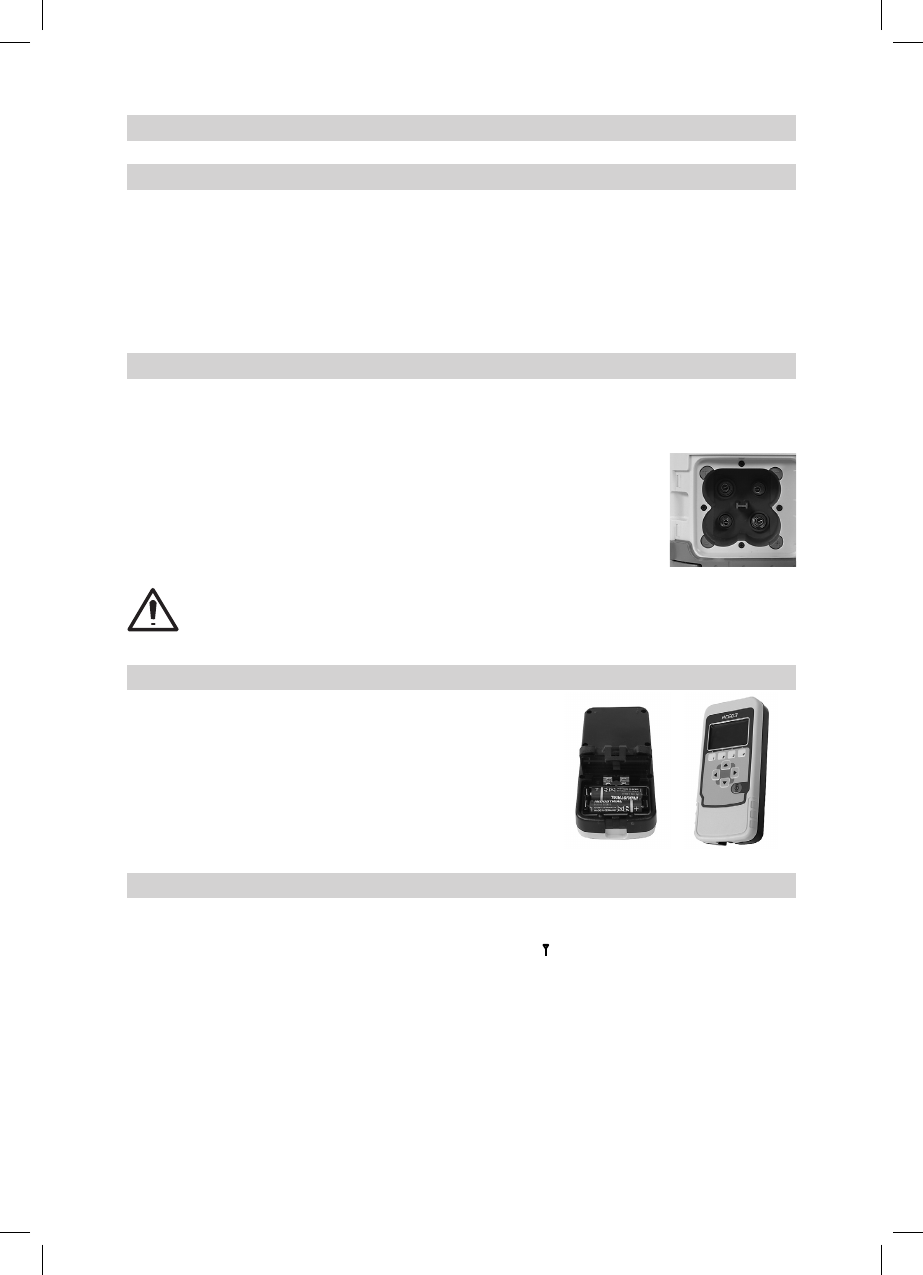
RC603 Radio/IR Remote Control
Powering the RC603
1. Open the battery door using a coin or similar pry device to release the
batterydoortabontheRC603.RC603willbeshippedwithalkaline
batteriesRechargeablebatteriescanbeusedoptionalbutneedto
bechargedexternally
2.InserttwoAAbatteriesnotingtheplus(+)andminus(-)diagrams
inside the battery housing.
3.Close the battery door. Push down until it “clicks” into the locked
position.
Turning On/Off the Radio/IR Remote Control
Theradio/IRremotecontrolisahand-helddevicethatallowsyoutosendoperationalcommandstothelaser
from a remote location.
Pressthepowerbuttontoturnontheradio/IRremotecontrol.A“ ”andadditionalverticalbarsappearin
the right corner of the remote’s top display line indicating the radio connection status between the laser and
theremotecontrol.IftheRC603isoutsidetheradiooperatingrangetheremoteswitchesautomaticallyinto
theIRconnectioncapability.
Note:Whentheremotecontrolisinitiallyturnedon,thestandarddisplay(modelnumberandsoftwareversion)
appearfortherst3seconds,thentheaxessymbolsandlast-enteredgradeforeachaxisbrieyappearin
theLCD.
Witheverybuttonpress,theLCDbacklightisactivatedandturnsoffautomaticallyifnobuttonispressedfor
8seconds.
To turn off the radio remote control, press and release the power button.
Note:5minutesafterthelastbuttonpress,theremotecontrolturnsoffautomatically.
120432trimble_UL633_01_GB.indd 3 14.04.12 11:40
4
LASER SETUP
Position the laser horizontally (tripod mount and rubber feet downward!) on a stable platform, wall mount or
tripod at the desired elevation.
The laser recognizes automatically whether it is used horizontally or vertically when switched on.
Turning On/Off the laser
PressthepowerbuttontoturnOn/Offthelaser.
Note:Dependingonthesetup(horizontalorvertical)andifagradevaluehasbeendialedin,theunitstarts
thetemperature/referencecheckwhilethethermometersymbolisashing.
Whenthetemperature/referencecheckhasbeennished,thestandarddisplayappearsandthebubblesymbols
ashuntilself-levelinghasbeencompleted.
Iftheself-levelingcan’tbenishedbasedontheselectedsensitivity,anerrormessageappears.
AbubblesymbolhelpstoadjusttheunitatthecrossaxiswhensetupverticalforautomaticSpotAlignorin
vertical manual mode.
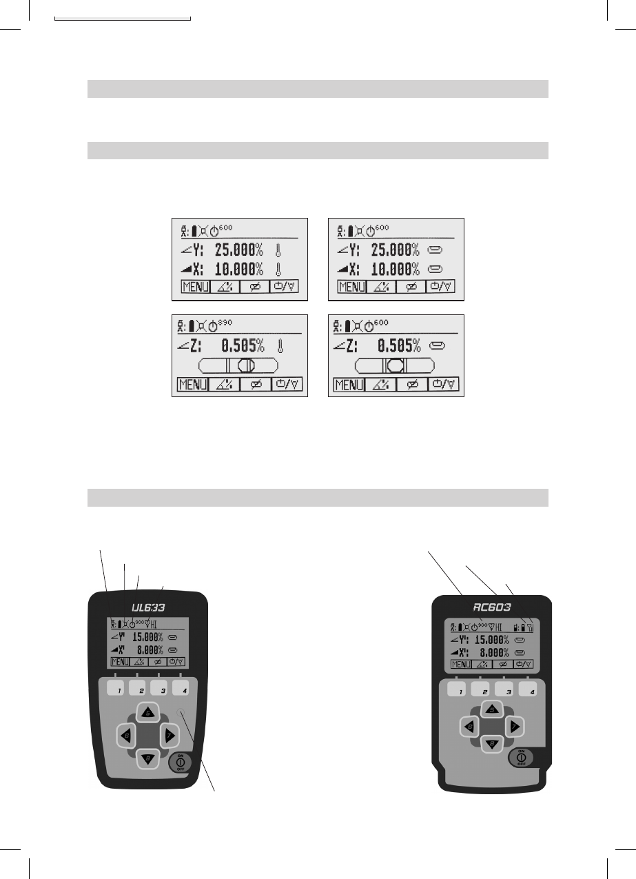
Features and Functions
Standard Display
TheremotecontrolmirrorsthefunctionalityoftheULkeypad
Button 1: Quickly press and release starts the
MENU entry.
Button 2: Quickly press and release starts the
grade entering mode.
Button 3: Quicklypressandreleaseactivates/
deactivates the manual mode.
Button 4: Quickly press and release to toggle
through the pre-selected rotation
speeds. Press and hold for three
seconds changes the unit into scan
mode.Wheninscanmode,quickly
press and release button 4 toggles
through the pre-selected scan sizes.
Button 5, 8:up/downarrowbuttons.
Button 6, 7:left/rightarrowbuttons.
Button 9: ON/OFFbutton-pressfor1secondto
turnontheunit;pressandholdfor2
seconds to turn off the unit.
Leveling/Standby – LED (green/red)
Batterystatuslaser HIalertfunctionisactivated
Maskselection BatteryStatusRemoteControl
StatusRadioConnectivity
Rotationspeed/Scanangle
FanBeamisactivated
120432trimble_UL633_01_GB.indd 4 14.04.12 11:40
5
Standard Features
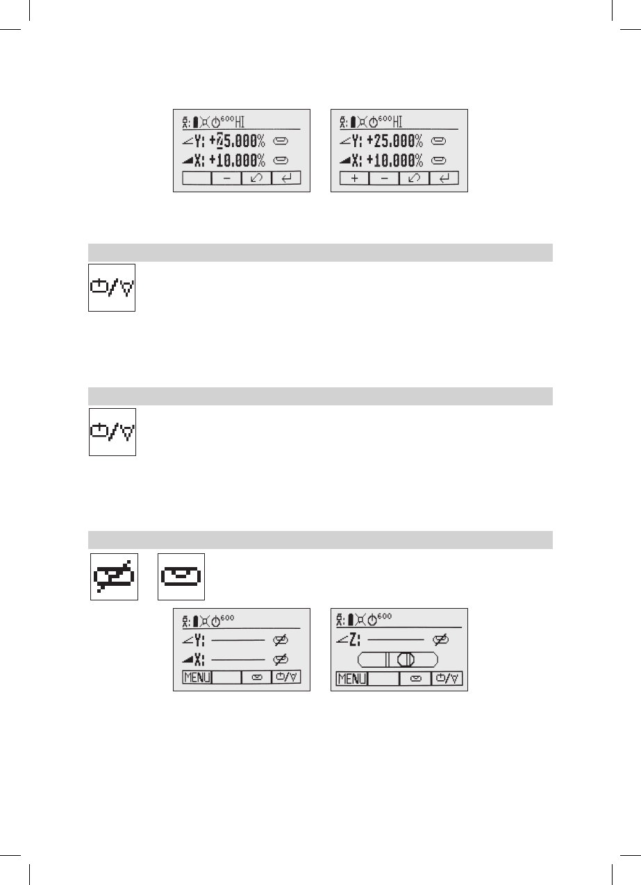
X-Y-Z-grade entering – Step and Go mode
Quickly press and release button 2startsthegradeenteringmode.Bothgradevalueswillbeshown.
Press/releasebutton1 a grade reverse Y
Press/releasebutton2 a grade reverse X
Press/releasebutton3 a return to the standard display
Quickly press and release button 4toconrmtheselectedgradevalueand
return to the standard display
Press and hold button 6 or 7(left/right)tochangeX-axisgradevalueafterthecomma;pressandholdbuttons
6 + 7simultaneouslystartsX-axisquickchangemodewherethegradevalueinfrontofthecommawillbeset
to 0% and then starts changing in 1% increments.
Press and hold button 5 or 8(up/down)forchangingY/Z-axisgradevalue;pressandholdbuttons 5 + 8
simultaneouslystartsY/Z-axisquickchangemodewherethegradevalueinfrontofthecommawillbeset
to 0% and then starts changing in 1% increments.
Note: The speed of the grade value change increases with the amount of time the button is held down.
Note: Thegradevalueforbothaxesincreasesin1.00%increments.Whenthegradevalueforeitheraxis
reachesitshighestamount,thegradevalueswitchestothelowestvalueforthataxis.Forexample,thevalue
switchesfrom+25%to-25%.
Thelaserwillself-leveltotherequiredgradepositionafterconrmingthegradechangewithbutton4.
Note:Thebubblesymbolsatthelaser’sLCDwillashuntilthelaserhasbeenself-leveledtotherequested
grade position.
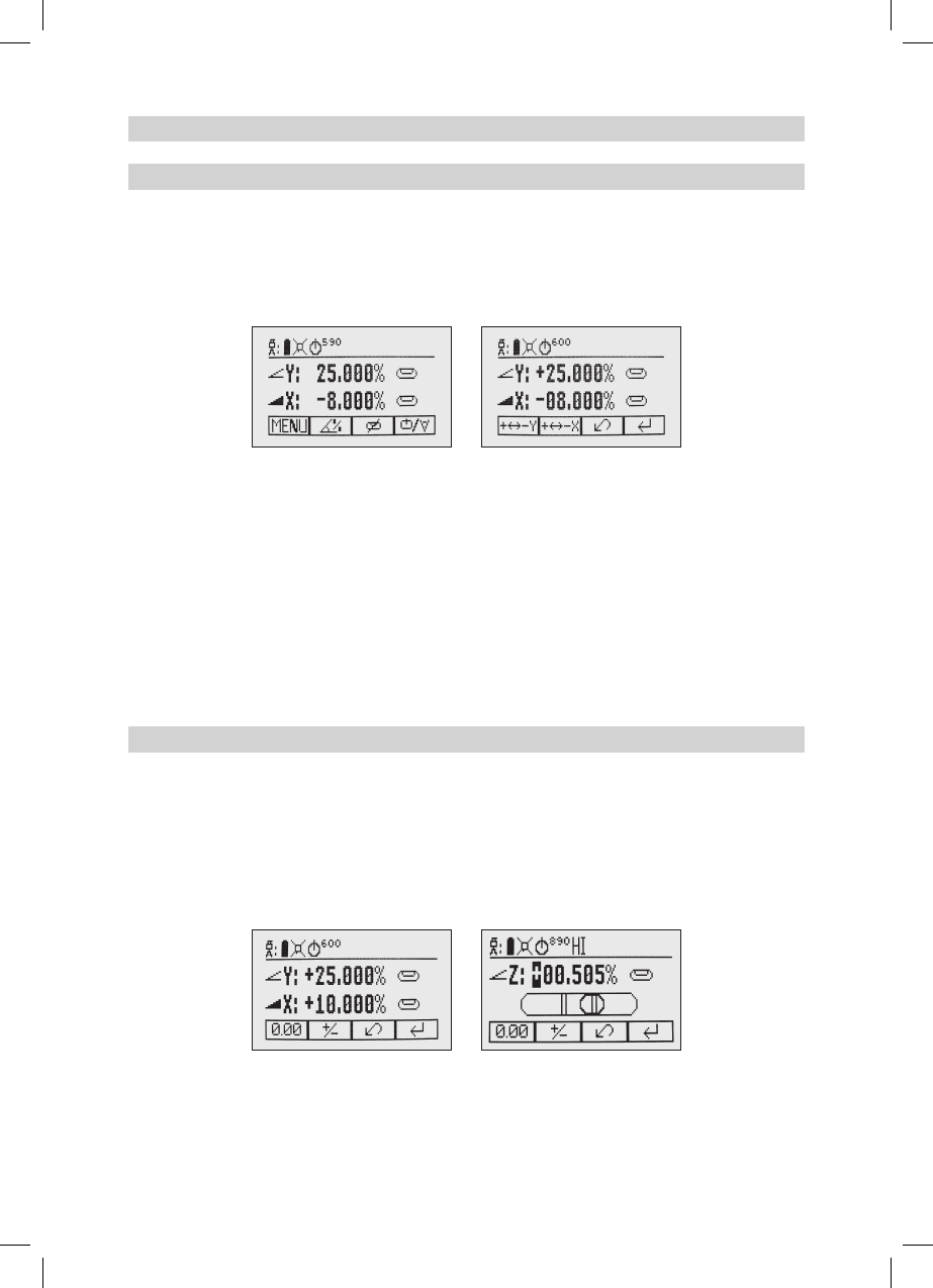
X-Y-Z-grade entering – Digit Select mode (Default)
Quickly press and release button 2 starts the grade entering mode. .
Bothgradevalueswillbeshown.
Press/releasebutton1 aquicksetto0%
Press/releasebutton2 a change the sign in front of the grade value
Press/releasebutton3 a return to the standard display.
Quickly press and release button 4toconrmtheselectedgradevalueandreturntothestandarddisplay.
Press and release button 5 or 8(downorup)tomovethecursortotheX-orY-axis(notusedinZ-mode)
Pressing and releasing button 6 or 7(rightorleft)movesthecursortotheright/left.
120432trimble_UL633_01_GB.indd 5 14.04.12 11:40
6
Usebutton 1 or 2(PlusorMinus)tosetthedesireddigit.
Thelaserwillself-leveltotherequiredgradepositionafterconrmingthegradechangewithbutton4.
Note: Thebubblesymbolsatthelaser’sLCDwillashuntilthelaserhasbeenself-leveledtotherequested
grade position.
Using the Rotation mode
Repeatedlypressingthebutton4togglesthrough0,80,200,600,900rpmregardlessiftheunit
is in automatic or manual mode.
At0rpm,thebeamstopsautomaticallyclosetothe+Y-axiscenterposition(pipelayingover
the top).
Whensetup inautomaticorgrademode,usingbuttons5/8increases/decreasesrotorspeed
from0to80andthenupto900rpmcontinuouslyin10rpmincrements.
Pointing mode
At0rpm,buttons6/7movethebeamtotheleft/rightside.Whensetupverticallyat0rpm,button5/8 move
thebeamclockwise/counterclockwise.
Note: Press and hold button 4 for three seconds to change the unit from rotation mode (default) into scan mode.
Using the Scan mode
Press and hold button 4attheStandardDisplayforthreesecondstochangetheunitintoscan
mode.
Quickly press and release button 4totogglebetweenthepre-selectedscansizes5,15,45,90,
180degreesand0;regardlessiftheunitisinautomaticormanualmode.
Whenworkinginhorizontalautomaticmode,pressandholdbutton5/8toincrease/decreasethe
linesizein5degreesincrements.Pressandholdbutton 6/7movesthescanlinetotheright/leftdirection.
Whenusedinautomaticverticalmode,pressingandholdingbutton5/8movesthescanlinecounterclockwise/
clockwise.Whensetupvertical,pressingandholdingbutton6/7movesthescanlineintotheright/leftdirection
regardless if in automatic or manual mode.
Note: Press and hold button 4 for three seconds to change the unit back to rotation mode (default) mode.
Manual mode
Pressing and releasing button 3attheStandardDisplayactivates/deactivates
the manual mode regardless if set up horizontal or vertical.
Manual mode is indicated by horizontal lines next to the axes symbols.An
additionalbubblehelpstoadjustthelaseronthecrossaxiswhensetupvertical.
InManualmode(horizontal),theY-axiscanbeslopedbypressingtheUp-(5)andDown-Arrow-(8) buttons on
thelaser‘skeypadortheremotecontrol.Additionally,theX-axiscanbeslopedbypressingtheLeft-(6) and
Right-(7)Arrow-buttonsonthelaserorremotecontrol.
Inverticalmode,theupanddownarrowbuttonsadjusttheZ-axisslope,andtheleftandrightarrowbuttons
alignthelaserbeamtotheright/leftside.
To resume automatic self-leveling mode, press the manual button again.
120432trimble_UL633_01_GB.indd 6 14.04.12 11:40
7
Special MENU Features
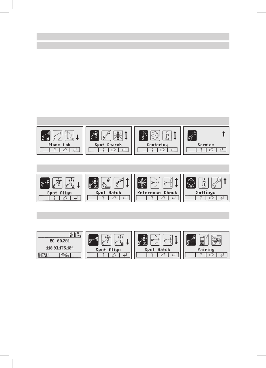
Menu Functions (Radio controlled)
Press and release button 1attheStandardDisplaytoentertheMENU.
The menu offers always only the features which can be selected depending on the setup (horizontal
or vertical).
The icon of the selected function will be highlighted.
A down arrow at the the right site indicates that the user can scroll down through the menu using the
button 8 (down arrow).
Aftergoingtothenextmenurow,anup/downarrowatthetherightsiteindicatesthattheusercanscrollup/
down through the menu (4 different screens) using the buttons 5/8(up/downarrows).
Pressing and releasing button 3 changes the unit always back to the standard or previous display.
Press and release the buttons 6/7 until the desired icon at the selected menu row is highlighted.
Press and release button 4toopenthesubmenuORstarttheselectedfunction.
Menu functions when set up horizontal
Menu functions when set up vertical
Menu Functions (IR controlled)
IftheRC603ispairedwithatransmitterandtheradioconnectiondoesn’twork,e.g.,throughapipe,theIR
connection offers the following functions.
PressandreleasetheMENUbuttonattheStandardDisplay.
Pressing and releasing button 3 changes the unit always back to the standard or previous display.
Press and release the buttons 5 to 8 until the desired icon is highlighted.
Press and release button 4toopenthesubmenuORstarttheselectedfunction.
Note: Pairing function is needed to pair an already paired remote with a new transmitter.
The new transmitter has to be set to the pairing dialog for this operation. Otherwise the pairing can not be
successful processed.
The pairing information of the previous pairing is still stored in the previous paired transmitter and should be
deleted in the pairing dialog of this transmitter
Note:IfaremoteispairedwithatransmittertheIRsignalsoftheremote(incaseofaninterruptedradio
connection) will transmitted in a private mode so that only the paired transmitter can received these IR
commands.
120432trimble_UL633_01_GB.indd 7 14.04.12 11:40
8
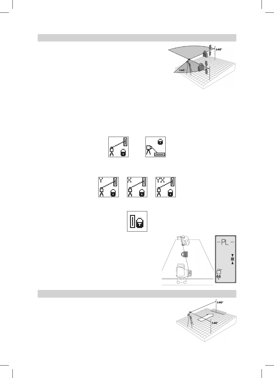
Automatic PlaneLok mode
The PlaneLok mode can be activated in horizontal and vertical
automatic and manual mode.
InPlaneLokmodewhensetuphorizontal,thebeamwillbelocked
toaxedelevationpoint(upto80m(260ft)locatedononeor
bothaxesateachsideofthelaser.
Forkeepingverticalalignmentsxedtoadirectionpoint,PlaneLok
canbeusedinbothdirectionsontheX-axis.
1. Set up the laser over the reference point.
2.AttachtheHL750receivertoagraderod.Placethereceiver
atthesecondpointandadjustittotheOn-gradeposition.Thereceivershouldbepermanentlymountedat
this location and at the desired elevation.
3.Usethesightingguidesonthetopofthelasertoalignthelasertothereceiver.Turnthelaseronthetripod
untilitisroughlyalignedtothereceiver’sposition(thealignmentrangeforbothaxesis+/-40°).
4.PressandreleasetheMENUbuttonattheStandardDisplayandselectPlaneLok.
Inverticalmode,PlaneLokcanbestartedimmediatelybypressingbutton4.
Horizontalsetup Vertical setup
5.Whensetuphorizontally,pressandreleasebutton4toopenthePlaneLoksubmenu;selectthedesired
PlaneLokaxisthenpressbutton4 to start PlaneLok.
Note:Thelaserstartstosearchforthereceiver.AashingReceiverandLocksymbolappearsattheselected
axisandbecomessolidwhenPlaneLokhasbeencompleted.
Note:Whenusedinverticalmode,thereceiverhastobeplaced
with the photocell on the bottom side.
The HL750 display shows a ashing –PL– during the time the
laserissearchingandadjustingthebeamtotheon-gradeposition.
When PlaneLok is complete, –PL– stops ashing at the HL750
display.
Note: The laser continues to servo to the receiver’s signals.
6.ExitingofPlaneLokcanbedonebypressingbutton3(ESC).
Automatic Grade Match
TheGradeMatchmodecanbeactivatedinhorizontalautomaticand
manual mode.
InGradeMatchmode,thelasercanbeusedtomeasuretheexisting
gradevaluebetweentwoknownelevationpoints(upto80m(260ft)
locatedononeorbothaxesateachsideofthelaser
1. Set up the laser over the reference point.
mm
120432trimble_UL633_01_GB.indd 8 14.04.12 11:40
9
2.AttachtheHL750receivertoagraderod.Checkthelaser’selevationnexttothelaserthenpositionthe
receiveratthesecondpointWITHOUTchangingthereceiver’selevationontherod.
3.Usethesightingguidesonthetopofthelasertoalignthelasertothereceiver.Turnthelaseronthetripod
untilitisroughlyalignedtothereceiver’sposition(thealignmentrangeforbothaxesis+/-40°).
4.PressandreleasetheMENUbuttonattheStandardDisplayandselectGradeMatch.
5.SelectthedesiredGradeMatchaxisthenpressbutton 4tostartGradeMatch.
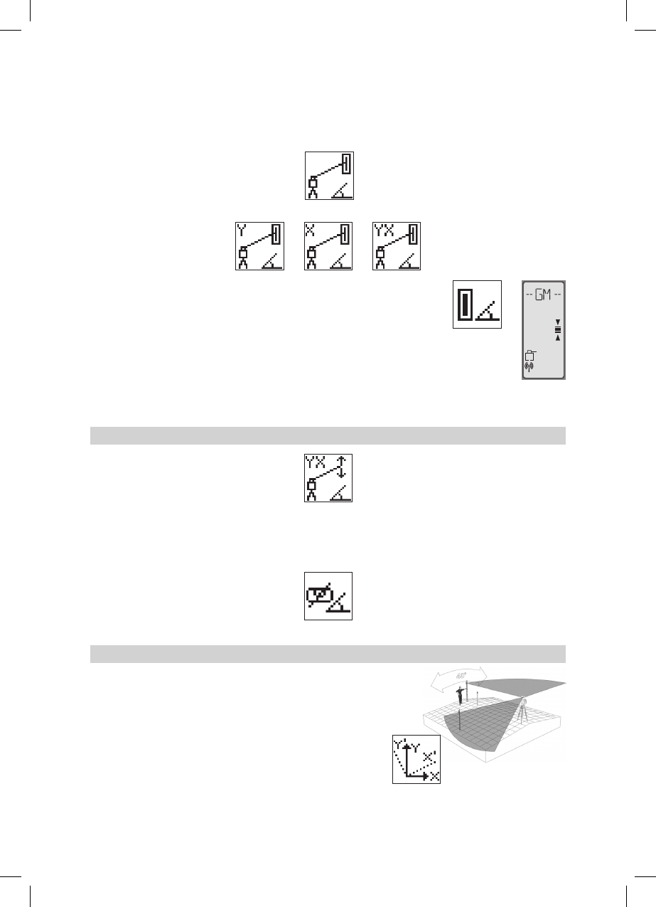
Note:Thelaserstartstosearchforthereceiver.AashingReceiverandangle
symbolappears at theselected axis anddisappears when GradeMatch has
been completed.
Whilethelaserissearchingandadjustingthebeamtotheon-gradeposition,the
HL750displayshowsaashing–GM–.
WhenGradeMatchhasbeencompleted,theHL750goesbacktothestandard
elevationdisplay.Theremotecontrolaswellasthelaserwilldisplaythenal
measured grade value.
Note:IfGradematchcan’tbecompletedbycheckingthelimits,thelasercomes
withanErrormessage(GradeMatchhasFailed)whichcanbedeletedwithbutton4(OK).TheHL750goes
back to standard elevation indication.
Manual Grade Match
InManualGradeMatch,thebeamonbothaxescanbeadjustedtothereceiver‘son-gradeposition,e.g,when
otherreceiversastheHL750areused.ThegradefortheY-axiscanbeadjustedwithbutton5/8 while button 6/7
adjusttheX-axis.DuringManualGradeMatchacrossedvialandanglesymbolappearnexttothecontinuously
changingY-andX-axisgradevalue.Afteradjustingtothereceiver’son-gradeposition,pressbutton2 (OK) to
gobacktoautomaticmodewherethenalgradevaluewillbeshownforbothaxes.
Note: Pressing button 3(ESC)exitsManualGradeMatchandchangestheunittomanualmode.
Automatic Axis Alignment
AutomaticAxisAlignment mode adjusts automatically the direction
thegradeaxisispointingtothereceiver’slocationbyanelectronically
simulationofrotatingtheunitonitsbasetomatchthehub.UsingAxis
Alignment,thelaseraxescanbealignedtooneortwodirectionhubs
(upto80m(260ft)locatedononeorbothaxesateachsideofthelaser.
1. Set up the laser over the reference point.
2.Place the grade rod with the attached HL750 receiver at the
desired direction hub.
3.Usethesightingguidesonthetopofthelasertoalignthelaserto
the receiver. Turn the laser on the tripod until it is roughly aligned
tothereceiver’sposition(thealignmentrangeforbothaxesis+/-40°).
mm
120432trimble_UL633_01_GB.indd 9 14.04.12 11:40
10
4.PressandreleasetheMENUbuttonattheStandardDisplayandselectAxisAlign.
5.Selectthedesiredaxisthenpressbutton4tostartAxisAlign.
Note:Adjusting thereceiver into the beam beforestarting the automaticAxisAlignmentreduces the time
neededfornishingthealignment.
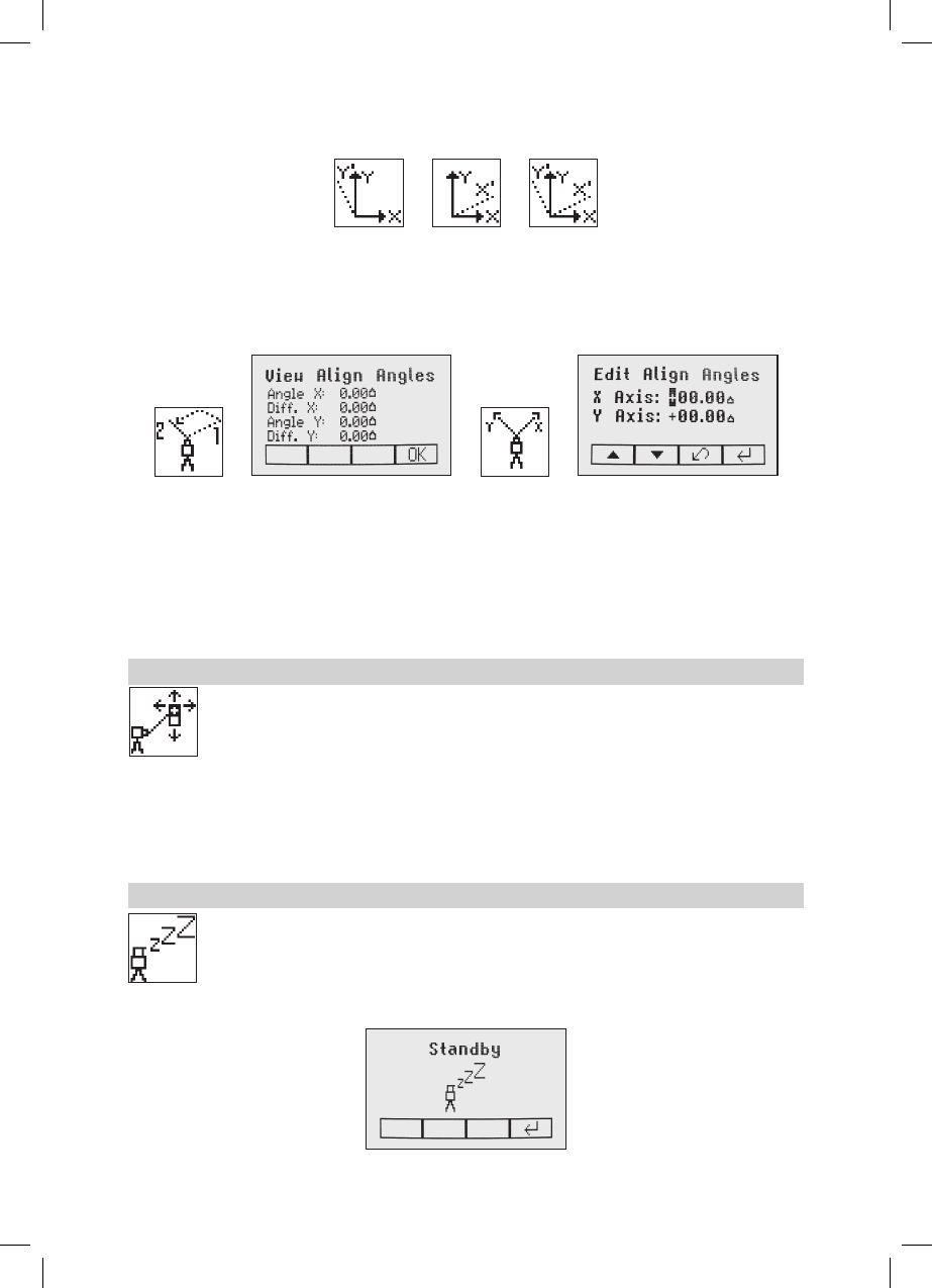
Selecting the menu icon „View Axis Angle“showsthealignmentangle after an axisalignmenthas been
completed. This function can be used to measure an angle difference between two direction hubs in a range
uptomax.80°byperformingtwoaxisalignmentsinsequence.
The menu icon „Axis Angle Input“selectionallowstodialinanaxisanglewheretheaxisdirectionwillbe
alignedtooafterarstaxisalignmenthasbeendone.Tworowsareavailablefortypinginaxisanglevalues.
Button5 and 8canbeusedtotogglebetweenbothrows.Changingthesignandnumberscanbedoneusing
the buttons 1 and 2.
Press and release button 4toconrmtheselectedaxisangles.Theaxeswillbeadjustedwhilethedisplay
fallsbacktothemainMenu.
Press and release button 3(ESC)toexittheAnglefunctions.
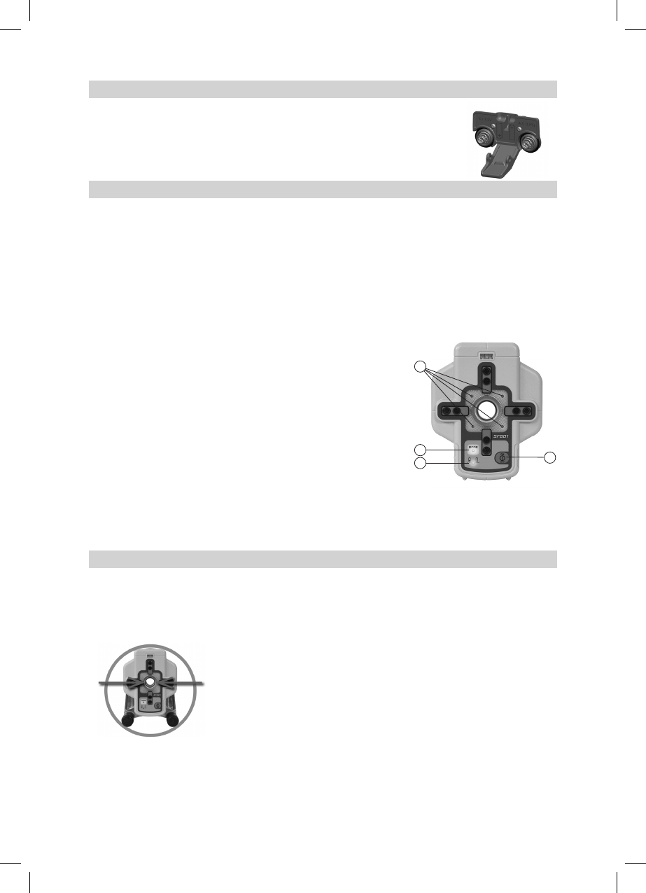
Manual Spot Search mode
The Spot Search mode is used for detecting the plumb beam manually using the Spot Finder
SF601andcanbeactivatedinhorizontalandverticalautomaticandmanualmode.
PressandreleasetheMENUbuttonattheStandardDisplayandselectSpotSearch.
Pressing button 4activatesthefanbeamwhiletherotationspeedchangesto900rpmandthe
unit goes back to the standard display.
The4redLEDsaroundthecenterholeguidetheusertotheplumbbeam‘scenterposition-all4LEDson=>
conrmationtheSF601hasbeensettothecorrectcenterposition.
Note:ManualSpotSearchcanalsobeactivatedanytimebyturningontheSpotFinderSF601.
TurningOfftheSF601deactivatestheSpotSearchmodeimmediatelybydeactivatingthefanbeam.
Activating/Deactivating Standby mode
PressandreleasetheMENUbuttonattheStandardDisplayandselectStandby.
Pressing and releasing button 4 activates the Standby mode.
Theself-levelingwillbestoppedandthebeamwillbeturnedoffwhiletheHIalertisstillactive.
ThedisplayshowsthestandbysymbolandtheLevel/StandbyLEDashesredevery5seconds.
To deactivate Standby mode and restore full operation of the laser, press and release button 4.
120432trimble_UL633_01_GB.indd 10 14.04.12 11:40
11
Start Reference Check
Before starting some grade work which is very sensitive an additional Reference Check can
bestartedmanually. Press and release the MENUbuttonattheStandardDisplayandselect
ReferenceCheck.
Pressing and releasing button 4startstheReferenceCheckconsideringthecurrenttemperature
insidethehousing.Whiletherotorchecksthecorrectpositiontherotationwillbestopped.
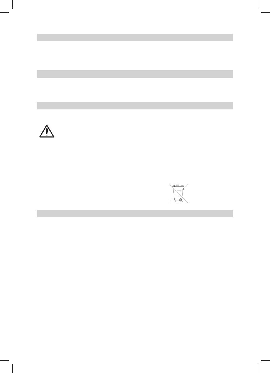
Centering the Rotor
PressandreleasetheMENUbuttonattheStandardDisplayandselectCenteringwheretherotor
willbecentered90°perpendiculartothebottomhousing.
Pressing and releasing button 4 starts the rotor centering function while the rotor checks the
limitsofbothaxesthenitstopsatthecenterpositionandchangestheunitintomanualmode.
Setting Menu
PressandreleasetheMENUbuttonattheStandardDisplayandselectSettings.
Press and release button 4toopentheSettingMenu;selectthedesiredfunctionthenpressbutton
4toopentheselectedsubmenufunctionORstarttheselectedfunction.
PleaseseetheSettingMenudetailsattheendoftheuserguide.
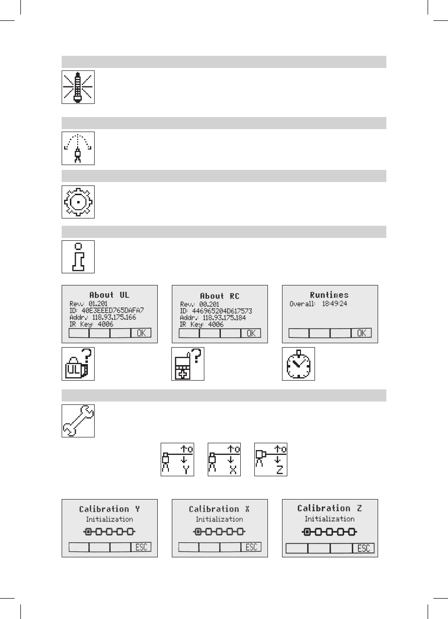
Info
PressandreleasetheMENUbuttonattheStandardDisplayandselectInfo.
Buttons6/7canbeusedtotogglebetweenUL,RCandRuntime.
Press and release button 4toconrmtheselection.
TheUL/RCinformation(softwareversion,ID,etc.)ortheruntimeoftheULwillbedisplayed.
Service
PressandreleasetheMENUbuttonattheStandardDisplayandselectService.Buttons6/7 can be
used to toggle between Calibration Y and Calibration XOR Calibration Z when set up vertically.
Press and release button 4 to conrm the selection.The calibration at the selected axis starts the eld
calibration procedure.
120432trimble_UL633_01_GB.indd 11 14.04.12 11:40
12
The RC603 Service menu offers additional features:
RF IR options
Press and release button 4toconrmtheselectionandselectoneofthefollowingoptions:
RFOn;IRauto=>Radioonalltimes;IRwillbeactivatedautomaticallyafterradioconnection
has been lost.
RFOff;IROn=>RadioturnedOff;IRalwaysactivated
RFOn;IROff=>RadioturnedOn;IRalwaysOff
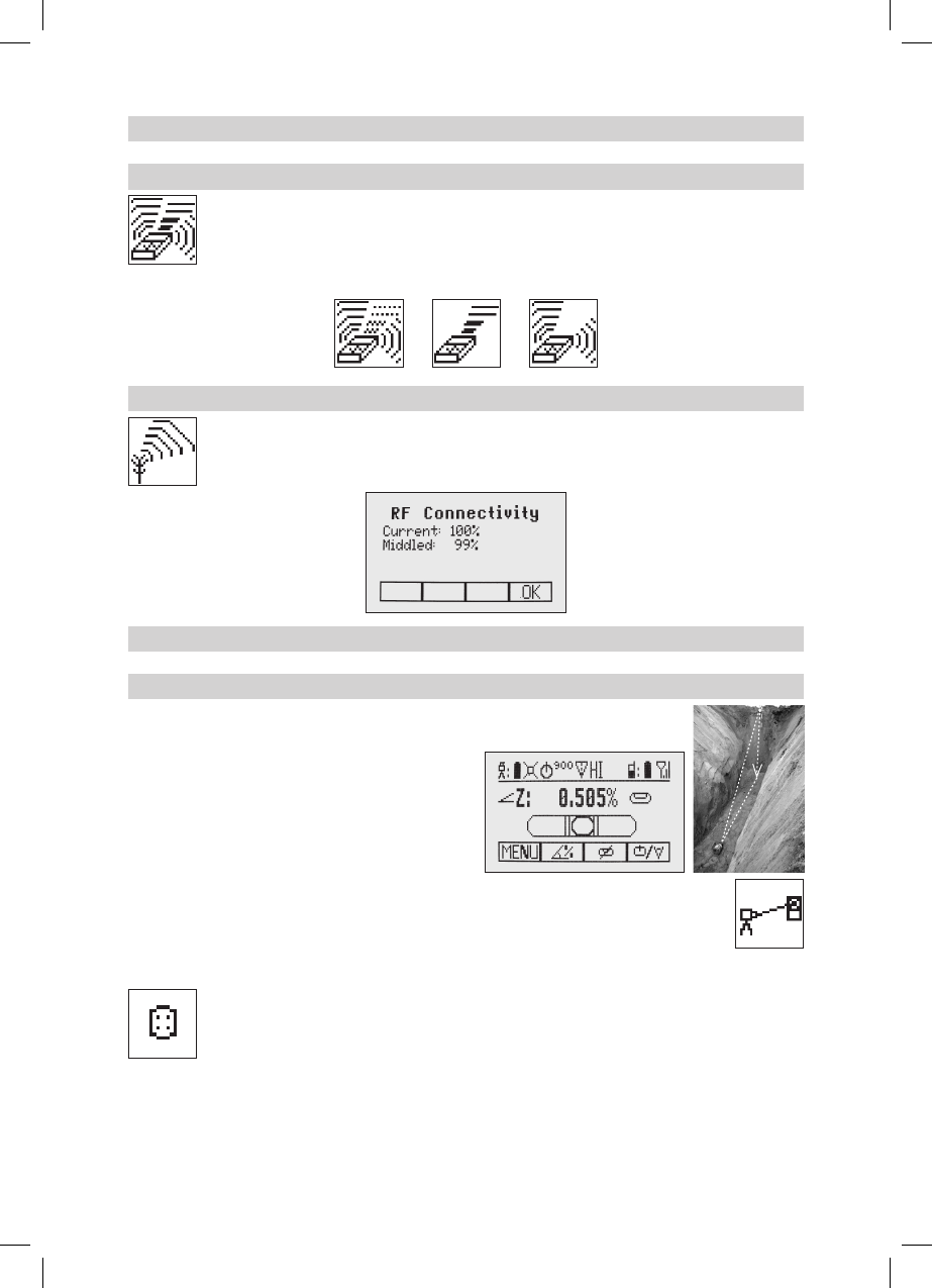
RF Connectivity
Press and release button 4togetastatusofthecurrentRadioconnectivity.
Special Features - Vertical Setup
Z-Axis Automatic Spot Align
TheSpotFinderSF601guidestheplumbbeamtothe
targetpointinthehorizontalaxis,whiletheZ-axisgrade
value will be maintained. Used for rst and second
day alignment (pipe laying applications). Using Spot
Alignment,theplumbbeamcanbealignedautomatically
toonedirectionhub(upto80m(260ft)locatedinfront
of the plumb beam.
1.Setupthelaseroverthestartpoint,e.g.,attherst
manhole ring.
2.Adjustthedisplaybubbletothecenteredposition.
3.TurnonandattachtheSF601SpotFinderatthedesireddirectionhub.
4.PressandreleasetheMENUbuttonattheStandardDisplay;selectSpotAlignandstartthe
function using button 4 (fan beam will be activated).
Note:SpotAligncanalsobestartedthroughthepipeusingtheRC603viainfrared.
Note:ThedisplayfallsbacktothestandarddisplaywhileaSpotFindersymbolisashing.
TheplumbbeamwillbeautomaticallyalignedtothecenteroftheSF601.
5.Afteralingmentiscomplete(all4redLEDsattheSF601areon),theplumbbeamwillmoveverticallytothe
previousdialedinZ-axisgradevalue.
Note:AutomaticSpotAligncanbeexitedanytimebypressingandreleasingbutton3(ESC).
120432trimble_UL633_01_GB.indd 12 14.04.12 11:40
13
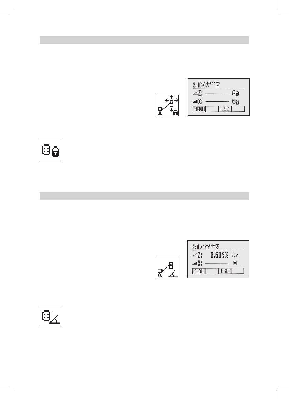
Z-axis Automatic Spot Lok
Automatic SpotLok (likePlaneLok)canbeusedtoalignandholdtheplumbbeamautomaticallytotheSF601’s
centerpointandcontinuouslyadjustingtheZ-andX-axisuntilexitingthismode.TheULlooksalwaystothe
centerpositionoftheSF601andre-adjuststhebeamimmediatelytothecentertoavoidanysetup/alignment
driftcausedbyvibrationsortemperatureinuences(e.g.whenworkingonconcretepads,facadeapplications).
UsingSpotLok,theplumbbeamcanbealignedautomaticallytoonedirectionhub(upto80m(260ft)located
in front of the plumb beam.
1. Set up the laser over the start point.
2.PlacetheSF601SpotFinderatthesecondreferencepoint.
3.Press and release the MENU button at the Standard
Display,selectSpotLokandstartthefunctionusingbutton
4 (fan beam will be activated).
Note: Spot Lok can also be started via infrared using the
RC603.
Note:ThedisplayfallsbacktothestandarddisplaywhileaSpotFinderandlockiconisashing.Theplumb
beamwillbeautomaticallyalignedtothecenteroftheSF601.
4.AfterSpotLokiscompleteall4redLEDsattheSF601areonandtheiconsstopashing.Thetransmitter‘s
plumbbeamisalwayscheckingforperfectalignmenttothecenteroftheSF601.All4LEDsashevery5
secondstoconrmthecorrectalignment.
Note:AutomaticSpotLokcanbeexitedanytimebypressingandreleasingbutton3(ESC).
Z-axis Automatic Spot Match
Automatic-Spot-Match canbeusedformeasuringanunknowngradevaluebetweentwoexistingelevations
e.g.,inanexistingpipewhichneedstobereplacedoranopentrenchwithanunknowngradevalue.
TheplumbbeamwillbeautomaticallyalignedtotheSF601centerpoint(Z-andX-axis)andswitchesback
toautomaticZ-axisgrademodewhiledisplayingthemeasuredZ-gradevalue.
UsingSpotMatch,theplumbbeamcanbealignedautomaticallytoonedirectionhub(upto80m(260ft)
located in front of the plumb beam..
1.Setupthelaseroverthestartpoint,e.g.,attherstpipe
or trench start point.
2.PlacetheSF601SpotFinderatthelastpipeorendof
the trench.
3.Press and release the MENU button at the Standard
Display, select Spot Matchandstart the function using
button 4 (fan beam will be activated)..
Note:SpotMatchcanalsobestartedviainfraredusingtheRC603.
Note:ThedisplayfallsbacktothestandarddisplaywhileaSpotFinderandanglesymbolisashing.The
plumbbeamwillbeautomaticallyalignedtothecenteroftheSF601.
4.WhenSpotMatchhasbeencompleted,thefanbeamwillbeturnedoffandtheULcalculatesthegrade
valuebetweenbothelevationpoints.ThecalculatedgradevaluewillbedisplayedattheUL‘sandRC‘sdisplay.
Note:AutomaticSpotMatchcanbeexitedanytimebypressingandreleasingbutton3(ESC).
120432trimble_UL633_01_GB.indd 13 14.04.12 11:40
14
Line Scan
Line Scan centers the rotor horizontally and can be used to align the plumb beam to a desired
horizontalposition.PressandreleasetheMENUbuttonattheStandardDisplayandselectLine
Scan. Pressing and releasing button 4 activates the Line Scan mode while the rotor checks the
limitsoftheX-axisandstopsatthecenterposition.
Pressing button 3(ESC)stopsthemovementandchangestheunitintomanualmode.
Correctionsupanddowncanbedoneusingbutton5/8;forleft/rightcorrectionsusebutton6/7.
Press and release the manual button to change the unit back to full automatic mode.
Beam Plunge
BeamPlungecenterstherotorverticallyandcanbeusedtoaligntheplumbbeamtoadesired
verticalposition,e.g.,whendoingInteriorlayout.
PressandreleasetheMENUbuttonattheStandardDisplayandselectBeamPlunge.Pressing
and releasing button 4activatestheBeamPlungemodewhiletherotorchecksthelimitsofthe
Y-axisandstopsatthecenterposition.
Pressing button 3(ESC)stopsthemovementandchangestheunitintomanualmode.
Correctionsupanddowncanbedoneusingbutton5/8;forleft/rightcorrectionsusebutton6/7.
Press and release the manual button to change the unit back to full automatic mode.
Setting Menu
PressandreleasetheMENUbuttonattheStandardDisplayandselectSettings.
Press and release button 4toopentheSettingMenu;selectthedesiredfunctionthenpressbutton
4toopentheselectedsubmenufunctionORstarttheselectedfunction.
TheSettingMenuoffersthefollowingfunctions:
Pairing Mask Mode Grade Entry Grade Display Sensitivity
HI-Alert Information Set Password Password On/Off RF-Channel
Select
Language
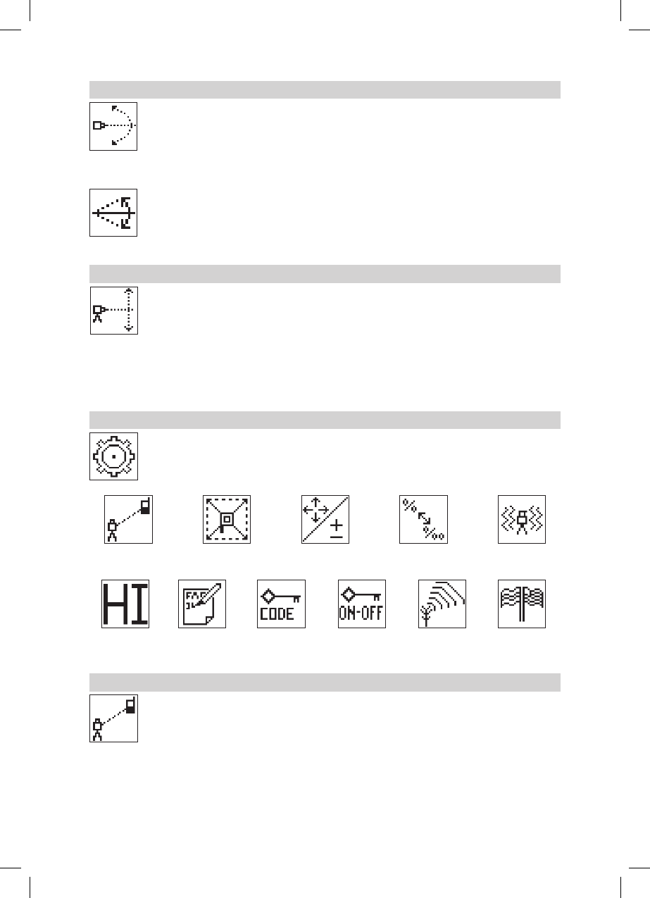
Pairing
WheninSettings,pressandreleasebutton4 to open the Pairing menu. The display shows the
currentlypairedunits(uptotworeceiversandtworemotecontrols).Ifalready2remotecontrols
have been paired, one of them has to be deleted using button 1(CLR).TurnontheRC603and
select the Pairing menu and press button 4.
TheUL633pairsnowautomaticallywiththenewremotecontrol.
120432trimble_UL633_01_GB.indd 14 14.04.12 11:40
15
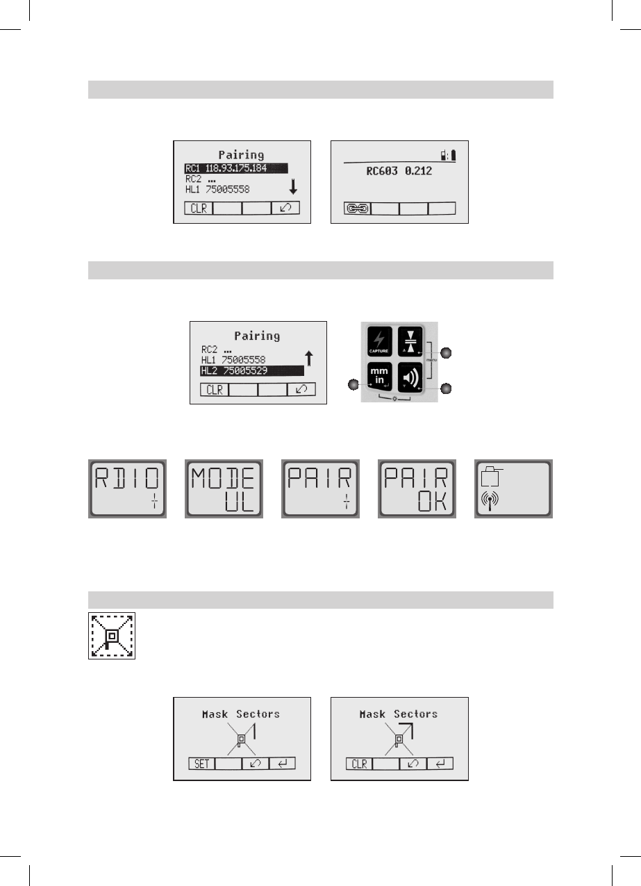
Pairing the transmitter with remote control
The chain symbol at button 1 indicates the remote has never been paired before which means no radio
connectivity is given. Pressing the pairing button 1willinitiateapairingrequest.Thetransmitterhastobein
pairing mode as shown above.
Note:Makesurethatpairingmodeisselectedonlyatonetransmitterwhichiswithintheradiorangeofthe
remoteduringapairingrequest.Otherwisepairingprocedurecanbeconfused.
Pairing the transmitter with receiver
To pair the transmitter and the receiver select Settings and press and release button 4 to open the Pairing
menu.Thedisplayshowsthecurrentlypairedunits(upto2receivers).Ifalready2receivershavebeenpaired,
one or both of them have to be deleted using button 1(CLR).
A
B
C
Next,turnonthereceiverthenpressandholdtheDeadband(A)andtheAudio(B)buttonsfortwoseconds.
AftertwosecondsthedisplayshowsMENUrst,thenRDIO.
PressandreleasetheUnits(C)button–displayshowsthecurrentradiomode.
IfnotalreadysettoUL,pressUnitsbuttonandthenpressDeadbandorAudiobuttonuntilULisdisplayed.
PressUnitsbuttonagaintoenterselection.PressandreleasetheAudiobutton–displayshowsPAIR.Press
theUnitsbuttonagain–thedisplayshowsPAIRandarotatingbar.AftercompletingPAIR,OKwillbedisplayed.
TheUL633pairsnowautomaticallywiththenewreceiver.PressandreleasethePowerbuttontwotimesto
exitthemenu.AlasersymbolislittoconrmthereceiverworksinULmode.
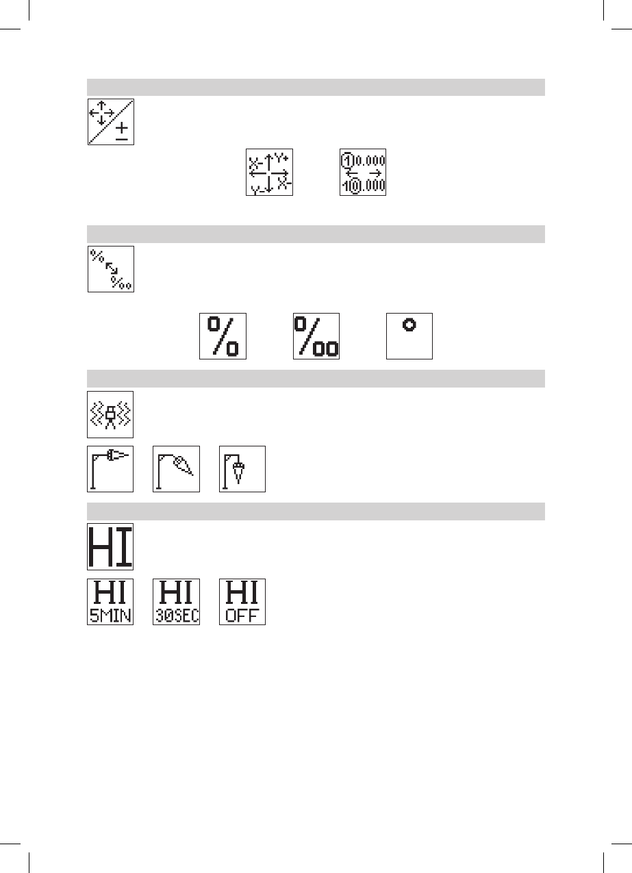
Mask mode
SelecttheMaskiconandpressandreleasebutton4toopentheMasksettingmenu.Depending
onwhichsideorcornerthebeamshouldbeturnedoff,therequiredsectorcanbeselected.Press
and release the buttons 5 to 8formovingashortashinglinearoundthemaskmodesymbol.For
selectingthesectorwherethebarisashing,pressandreleasebutton1(SET).Aftersettingthe
rstsector,button1changestoshowCLRwhichofferesthecapabilityofdeletingtheselectedmask
sectoragain.Usebutton5 to 8tomovetheashingbartootherrequiredareasandrepeatthesettingprocess.
Whenallareashavebeenset,pressbutton 4 to store the mask sector selection until the unit will be turned off.
Hinweis: The unit always powers up with the mask mode deactivated (default).
120432trimble_UL633_01_GB.indd 15 14.04.12 11:40
16
Grade Entry
SelecttheGradeEntryiconandpressandreleasebutton4toopentheGradeEntrymenu.
Buttons6/7canbeusedtotogglebetweenStepandGoandDigitSelect.
Press and release button 4toconrmtheselection.
Step and Go Digit Select
Grade Display
SelecttheGradeDisplayiconandpressandreleasebutton4toopentheGradeDisplaymenu.
ThedesiredGradeDisplayMode(Percent/Permille/Degree)canbeselectedusingthebuttons6/7.
Press and release button 4toconrmtheselecteddisplaymode.
Sensitivity Selection
Select the Sensitivity icon and press and release button 4 to open the Sensitivity menu. The
desiredSensitivity:Low,Mid(Default)andHigh)canbeselectedusingthebuttons6/7. Press
and release button 4toconrmtheselectedSensitivity.
HI-alert Selection
SelecttheHIiconandpressandreleasebutton 4toopentheHI-alertmenu.ThedesiredHI-alert:
5min.(Default),30secondsandHI-Off)canbeselectedusingthebuttons 6/7. Press and release
button 4toconrmtheselectedHI-alert.
120432trimble_UL633_01_GB.indd 16 14.04.12 11:40
17
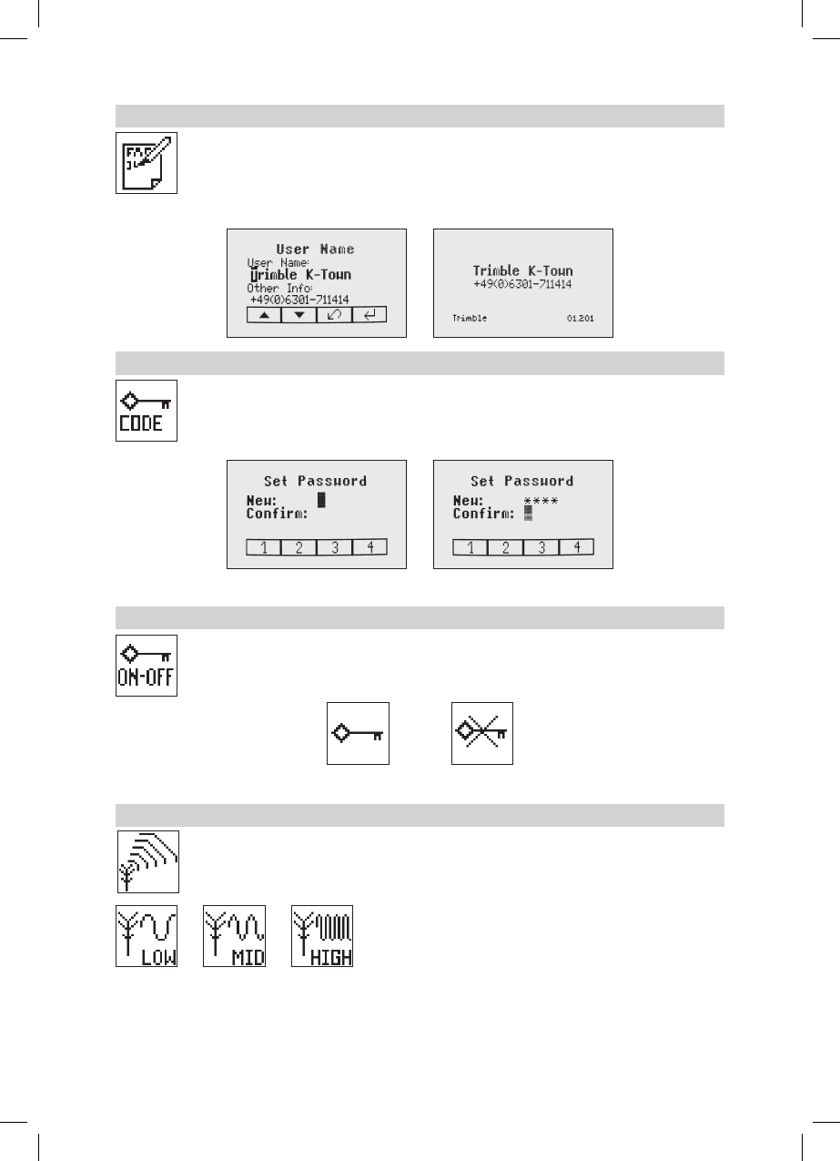
User Name
SelecttheUsernameiconandpressandreleasebutton4toopentheUsernamemenu.One
rowfortypingnamesinbigfont(15)andonerowinsmallfont(18)forlettersornumbersare
available.Button5 and 8canbeusedtotogglebetweenbothrows.Changingthecharacters
can be done using the buttons 1 and 2. Press and release button 4toconrmtheselecteduser
name.Thedisplayfallsbacktothemainmenu.Anytimetheunitwillbepoweredup,theUser
info will be displayed for couple seconds.
Set Password
Select the Set Password icon and press and release button 4toopenthePasswordmenu.Use
Button1 to 8 to type in a password containing of 4 digits and repeat the password at the second
row. Press and release button 4tostoretheselectedpassword;unitfallsbacktothestandard
menu.Afterpoweringuptheunit,thestandarddisplaycomesupifthecorrectpasswordwillbe
entered, otherwise the unit turns off automatically.
Password On/Off
SelecttheSetPasswordON-Officonandpressandreleasebutton4 to open the Password menu.
Buttons6/7 can be used to toggle between Password On and Password Off if a Password has
been entered before. Press and release button 4toconrmtheselection.
Password on Password off
Radio (RF) Channel
SelecttheRFChanneliconandpressandreleasebutton4toopentheRadioChannelmenu.
ThedesiredRFChannel:Low,Mid(Default),andHighcanbeselectedusingthebuttons6/7.
Press and release button 4toconrmtheselectedRFChannel.
120432trimble_UL633_01_GB.indd 17 14.04.12 11:40

18
Select Language
Select the Language icon and press and release button 4toopentheLanguagemenu.Usebutton
5 to 8toselecttherequiredlocallanguage(EN,DE,IT,FR,ES,PT,NL,DA,NO,SV,FI,PL).
Press and release button 4tostoretheselectedLanguage;unitfallsbacktothestandardmenu.
CALIBRATION
Checking Calibration of the Y- and X-Axes
1. Set up the laser 30 m (100 ft) from a wall and allow it to level.
2. Setthegradeto0.000%inbothaxes.
3. Raise/lowerthereceiveruntilyougetanon-gradereadingforthe+Yaxis.Using
the on-grade marking notch as a reference, make a mark on the wall.
Note: Forincreasedprecision,usethene-sensitivitysetting(1.5mm/1/16in.)on
the receiver.
4.Rotatethelaser180°(-Yaxistowardthewall)andallowthelasertore-level.
5.Raise/lowerthereceiveruntilyougetanon-gradereadingforthe–Y/axis.Usingthe
on-grade marking notch as a reference, make a mark on the wall.
6.Measurethedifferencebetweenthetwomarks.Iftheydiffermorethan3mmat30
m(1/8inchat100feet),thelaserneedscalibrating.
7.AftercheckingtheY-axis,rotatethelaser90°.Repeattheabovestartingwiththe
+Xaxisfacingthewall.
Checking Calibration of the Z-(vertical) Axis
To check vertical calibration, you need a plumb bob with at least 10m (30ft) of string.
1. Suspend the plumb bob in front of a house i.e., attached to a window frame whose window height is at least
10m (30ft).
2. Set up the laser in vertical so that the laser beam strikes the receiver’s on-grade position at the top of the string.
3.Lookforanydeviationusingthereceiverfromthetopofthestringtothebottomofit.Ifthedeviationismore
than1mm(<1/16in.),theverticalaxisneedscalibrating.
Note:Ifcalibrationisrequired,please,refertothecalibrationinstructionsonourTrimblewebsite
www.trimble.com/support.shtml.
120432trimble_UL633_01_GB.indd 18 14.04.12 11:40

19
Troubleshooting
Anyerrormessagecanbedeletedwithashortpressofbutton4 (OK). The table shows the related description
andpossiblesolutions.Thenextservicecentershouldbecontactedifadifferenterrormessageasshownat
the table will be displayed.
Error codes Description Solution
21 TemporaryEEpromproblem Repeatpairingandre-enterthe
customer settings
120 HIalert-UnitHeigtchanged Checklaserbeamelevationafter
deletingtheHIalert
130 MechanicalLimitduringAxis
Alignment,GradeMatchorSpot
Match
Re-aligntheclosertothe
alignmentpoint;checkifexisting
slopeisabove+/-25%
131 RakeAngleLimit Re-aligntheunitclosertothe
alignment point
140 Laser beam blocked Makesurethereareno
obstacles between the
transmitterandtheHL750or
SF601
141 Time Out - Function could not be
completed in the allowed time
Checkradiooperatingrange/
connection;checkstablelaser
setup
150 Noreceiver-Receivernot
availableforsingleaxis
automatic function
Makesurethereceiverisonand
paired
151 Noreceivers-Bothreceivers
are not available for automatic
alignment function
Makesurebothreceiversareon
and paired
152 Noreceiver-Thelasersearched
for the receiver but could not
ndit
Checktheoperatingrangefor
auto function and restart the auto
alignment
153 LostReceiver-Thelaser
searched and found the receiver
but then lost it
Checktheoperatingrangefor
auto function and restart the auto
alignment
160 X,YorZlevelsensordefect Contactservicecenter
120432trimble_UL633_01_GB.indd 19 14.04.12 11:40
20
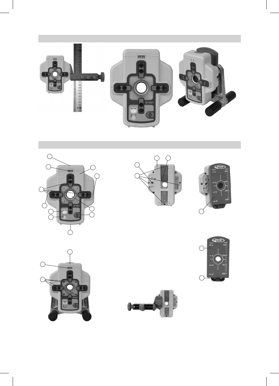
SF601 - User Guide
SF601attachedtoagraderod
using the standard receiver clamp
Components SF601
SF601attachedtothe
optional pipe laser target base
1. SF601
2. Slider
3. CenterHole
4. PowerButton
5. BubbleVial
6. BatteryLED
7. ModeLED
8. RedDirectionLEDs
9. IRtransmitters/receivers
10. Markingnotches(frontandback)
11. M6ClampMount
12. Batterydoor
13. LatchforBatteryDoor
14. ReleaseTabSlider
10
1
10
3
4
5
9
10
7
6
10
10
5
8
12
11
10
13
2
2
14
120432trimble_UL633_01_GB.indd 20 14.04.12 11:40
21
Powering the SF601
1. Open the battery door pulling the battery door latch.
TheSF601willbeshippedwithalkalinebatteries.
Rechargeablebatteriescanbeusedoptionalbutneedtobechargedexternally
2.Insert four AA batteries noting the plus (+) and minus (-) diagrams inside on the
battery door.
3.Closethebatterydoor.Pushdownuntilit“clicks”intothelockedposition.
SF601 - Features and Functions
1.Power/ModeButton:PressandreleasethepowerbuttontoturnONtheSF601.
AlldisplayLED’swilllightfor1.0sec.
Pressandholdpowerbuttonfor>1sec.toturnOFFtheSF601.After1sec.alldisplayLED’swilllight1.0sec.
Note: Wurde der SF601 eingeschaltet, wird durch kurzes Drücken der Ein-Aus-Taste die Fanbeam-Linse
aktiviert/deaktiviert(einevorhergestarteteAutomatikfunktionwirdsofortgestoppt).
LED’s:
2. LED1:
solidgreenwhenSF601isonandbatteryOK
blinkingredifbatteryvoltageis3,8V<Vbat<4V
solidredifbatteryvoltageis<3,8V;
SF601turnsoffautomaticallyafter5min.
3. Mode LED2:
yellow solid: automatic mode
ashing:noneorlostsignal
off: manual mode
4. Direction LEDs red:
Manualmode:pointingtowardsthecenteroftheplumbbeam.
All4LEDsaresolidredwhenthebeamiscentered.
AutomaticSpotLockmode:solidfor5min.,thenLED’sashevery5seconds.
Using the SpotFinder SF601 for vertical UL applications
WiththeUL633usingIRconnection,theSF601canbeusedinthreedifferentautomaticmodesAutomatic-
SpotAlignment,SpotLokandSpot-Matchandinadditioninamanual/display(SpotSearch)modetodetect
the plumb beam (fan beam).
Automatic-Spot Alignment: SF601guidesthebeamtothetargetpointin
thehorizontalaxis,whiletheZ-axisgradevaluewillbemaintained.Usedfor
rstandseconddayalignment(pipelayingapplications).
2
4
31
120432trimble_UL633_01_GB.indd 21 14.04.12 11:40
22
Using SpotLok mode (like PlaneLok) aligns and holds the plumb beam
automaticallytotheSF601centerpoint(bothaxes)untilexitingthismode.
Automatic-Spot-Match: (like Grade Match- two existing elevation points
will be connected to measure the grade value between these two points)
alignstheplumbbeamautomaticallytotheSF601centerpoint(bothaxes)
andmovesback to Z-axis automaticmodewhile displaying the measured
Z-axisgradevalue.
Note: WhenAutomaticSpotAlignmentandAutomaticSpot-Matchhavebeen
completed,theUL633turnsoffthefanbeamautomatically.
Note:WithaquickpressandreleaseoftheSF601powerbutton,thefanbeamlensattheUL633willbe
activated/deactivatedwhileapreviousactivatedautomodewillbeexited.
SF601 – Manual/Display Mode
WithaquickpressandreleaseoftheSF601powerbutton,thefanbeamlensattheUL633willbeactivated/
deactivatedwhileapreviousactivatedautomaticmodewillbeexited.
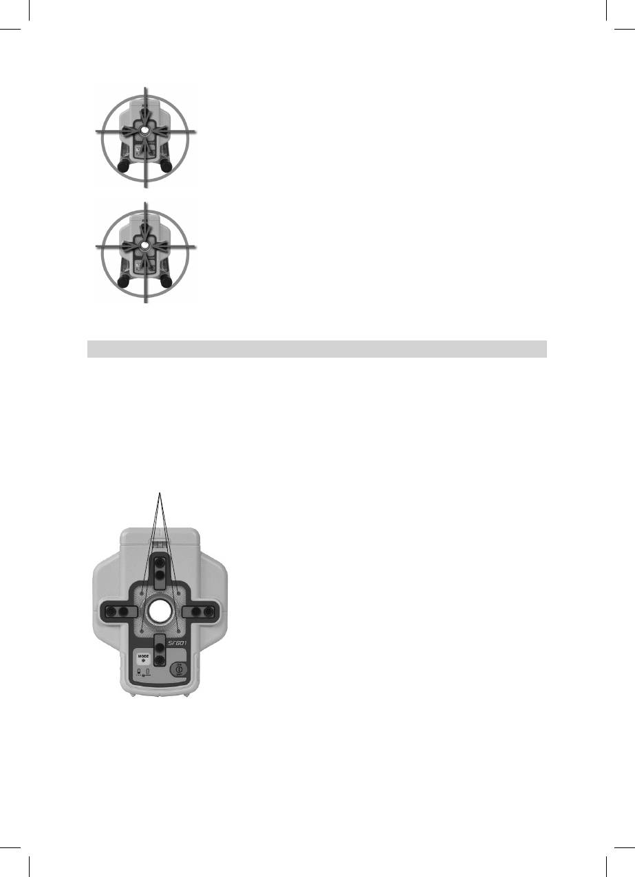
Manual/Display (Spot Search) mode:Ifthefanbeamlenswill beactivatedandnoautomaticmodehas
beenstarted,theSF601isinmanual/displaymodewheretheREDdirectionLEDsguidetheusertothecenter
position of the fan beam.
Note:IRcommunicationisdisabled.
ThedirectionLEDsworksimilarlikeusingthepipelasertarget,e.g.,ifthe left top LED is on,theSF601has
tobemovedtotheleft/uppositiontobringthecenterholeintothecenterofthebeam.
All4 LEDs are solid red when the beam is centered.
120432trimble_UL633_01_GB.indd 22 14.04.12 11:40
23
PROTECTING THE UNIT
Donotexposetheunittoextremetemperaturesortemperaturechanges(donotleaveinsidethecar).The
unitisveryrobustandcanresistdamageifdroppedevenfromtripodheight.Beforecontinuingyourwork,
alwayscheckthelevelingaccuracy.SeeCheckingCalibrationsection.Thelaseriswaterproofandcanbe
used indoors and outdoors.
CLEANING AND MAINTENANCE
Dirtandwaterontheglasspartsoflaserorprismwillinuencebeamqualityandoperatingrangeconsiderably.
Cleanwithcottonswabs.Removedirtonthehousingwithalint-free,warm,wetandsmoothcloth.Donotuse
harshcleansersorsolvents.Allowtheunittoairdryaftercleaningit.
PROTECTING THE ENVIRONMENT
The unit, accessories and packaging ought to be recycled. This manual is made of non-chlorine recycling
paper.Allplasticpartsaremarkedforrecyclingaccordingtomaterialtype.
Do not throw used batteries into the garbage, water or re. Remove them in compliance with
environmental requirements.Hinweis für Kunden in der EU
Notice to Our European Union Customers
For product recycling instructions and more information, please go to:
www.trimble.com/environment/summary.html
RecyclinginEurope:TorecycleTrimbleWEEE,
Call+31497532430,andaskforthe“WEEEAssociate”
or
Mailarequestforrecyclinginstructionsto:
TrimbleEuropeBV
c/oMenloWorldwideLogistics
Meerheide45
5521DZEersel,NL
Warranty
TrimblewarrantstheUL633tobefreeofdefectsinmaterialandworkmanshipforaperiodof5years.Trimble
or its authorized service center will repair or replace, at its option, any defective part, or the entire product,
forwhichnoticehasbeengivenduringthewarrantyperiod.Ifrequired,travelandperdiemexpensestoand
fromtheplacewhererepairsaremadewillbechargedtothecustomerattheprevailingrates.Customers
should send the product to Trimble Navigation Ltd. or the nearest authorized service center for warranty
repairsorexchange,freightprepaid.Anyevidenceofnegligent,abnormaluse,accident,oranyattemptto
repairtheproductbyotherthanfactory-authorizedpersonnelusingTrimblecertiedorrecommendedparts,
automaticallyvoidsthewarranty.Specialprecautionshavebeentakentoensurethecalibrationofthelaser;
however,calibrationisnotcoveredbythis warranty.Maintenanceofthecalibration is the responsibility of
theuser.TheforegoingstatestheentireliabilityofTrimbleregardingthepurchaseanduseofitsequipment.
Trimblewillnotbeheldresponsibleforanyconsequentiallossordamageofanykind.Thiswarrantyisinlieu
ofallotherwarranties,exceptassetforthabove,includinganyimpliedwarrantymerchantabilityoftnessfor
a particular purpose, are hereby disclaimed.
Thiswarrantyisinlieuofallotherwarranties,expressedorimplied.
120432trimble_UL633_01_GB.indd 23 14.04.12 11:40

24
TECHNICAL DATA
UL633
Leveling accuracy1,3: ±0.5mm/10m,1/16“@100ft,10arcseconds
Grade accuracy1,3: ±1.0mm/10m,1/8“@100ft,20arcseconds
Rotation: 0-900rpm
Scanmode: 5presetsizes+variableadjustment
Operational area1,2: appr. 400 m (1300 feet) radius with detector
Lasertype: reddiodelaser650nm
Laserclass: Class3A/3R,<5mW
Self-levelingrange: appr.±14°
Graderange(Y;X): ±25%bothaxes(notsimultaneously)
Graderange(Z): ±25%
Levelingindicators: LCDindicationsandLEDashes
Radiorange(HL750): upto80m(260ft)
Powersource: NiMHbatterypack
Batterylife1: 35hoursNiMH;40hoursalkaline
Operatingtemp.: -20°Cto50°C(-4°Fto122°F)
Storagetemp.: -20°Cto70°C(-4°Fto158°F)
Tripodattachments: 5/8x11horizontallyandvertically
DustandWaterproof: IP67
Weight: 3.1kg(6.8lbs)
Lowvoltageindication: LCDbatteryindicator
Low voltage disconnection: unit shuts off
1) at 21°Celsius
2) under optimal atmospheric circumstances
3) along the axis
4) depending on sun light conditions
Remote Control RC603
RadioOperatingrange1,3: up to 100 m (330 ft)
IROperatingrange1,4: upto80m(260ft)
Powersource: 2x1.5VAAalkalinebatteries
Batterylife1: 130 hours
DustandWaterproof: IP66
Weight: 0.26kg(0.4lbs)
Spot Finder SF601
Operating range1,4: upto80m(260ft)
Powersource: 4x1.5VAAalkalinebatteries
Batterylife1 : 30 hours
DustandWaterproof: IP67
Weight: 0.43kg(0.4lbs)
120432trimble_UL633_01_GB.indd 24 14.04.12 11:40

25
DECLARATION OF CONFORMITY
Please disregard the declaration of conformity within the manual.
Following is the valid declaration:
We
Trimble Kaiserslautern GmbH
Declareunderoursoleresponsibilitythattheproducts
UL633 and RC603/SF601
To which this declaration relates is in conformity with the following standards:
EN300 440-2 V1.1.1:2004, EN301 489-03 V1.4.1:2002, EN301 489-01 V1.4.1:2002, EN50371:2002,
EN60825:1994 + A1:2002 + A2:2001
following the provisions of directive R&TTE 1999/5/EC.
The managing director
ELECTRO-MAGNETIC COMPATIBILITY
Compliance statement (part 15.19)
This device complies with part 15 of the FCC Rules.
Operation is subject to the following two conditions:
(1) this device may not cause harmful interference, and
(2) this device must accept any interference received, including interference that may
cause undesired operation.
Warning (part 15.21)
Changes or modifications not expressly approved by the party responsible for compliance
could void the user’s authority to operate the equipment.
This in particular is applicable for the antenna which has been delivered with the
UL633 and RC603
Under Industry Canada regulations, this radio transmitter may only operate using an antenna
of a type and maximum (or lesser) gain approved for the transmitter by Industry Canada.
To reduce potential radio interference to other users, the antenna type and its gain should
be so chosen that the equivalent isotropically radiated power (e.i.r.p.) is not more than that
necessary for succesful communication.
120432trimble_UL633_01_GB.indd 25 14.04.12 11:40