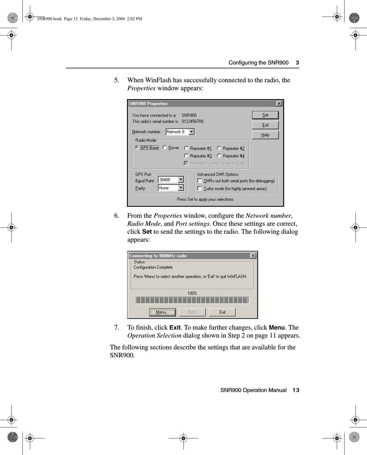
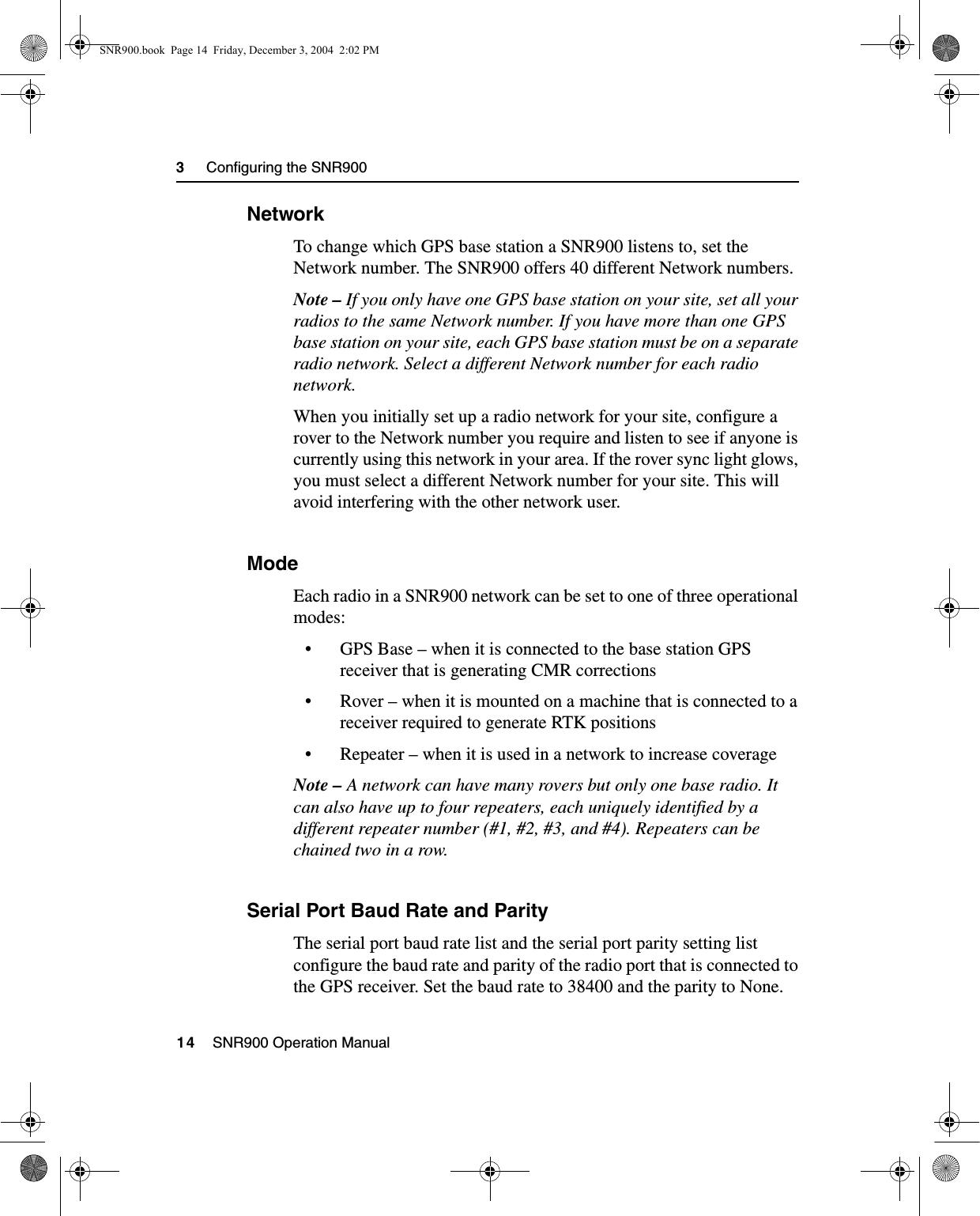
Trimble TC900C 900 MHz Radio Modem User Manual Trimble SNR900 Radio Modem Operation Manual

Trimble Navigation Ltd 900 MHz Radio Modem Trimble SNR900 Radio Modem Operation Manual

User Manual

FPart Number 52357-00-ENGRevision BDecember 2004Trimble® SNR900Radio-ModemOperation ManualSNR900.book  Page i  Friday, December 3, 2004  2:02 PM
Contact InformationTrimble Geomatics and Engineering Division5475 Kellenburger RoadDayton, Ohio 45424-1099U.S.A.800-538-7800 (toll free in USA)+1-937-233-8921 Phone+1-937-233-9004 Faxwww.trimble.comCopyright and Trademarks© 2001–2004, Caterpillar Trimble Control Technologies LLC. All rights reserved.Trimble, the Globe & Triangle logo, BladePro, and SiteVision are trademarks of Trimble Navigation Limited, registered in the United States Patent and Trademark Office and other countries. CMR+, MS750, MS860, SiteNet, and TRIMCOMM are trademarks of Trimble Navigation Limited.Microsoft, Windows, and Windows NT are trademarks or registered trademarks of Microsoft Corporation in the United States and/or other countries.All other trademarks are the property of their respective owners.Release NoticeThis is the December 2004 release (Revision B) of the SNR900 Operation Manual, part number 52357-00-ENG. It applies to version 1.0 of the SNR900 radio-modem.Hardware Limited WarrantyTrimble Navigation Limited warrants that this hardware product (the “Product”) will perform substantially in accordance with published specifications and be substantially free of defects in material and workmanship for a period of one (1) year starting from the date of delivery. The warranty set forth in this paragraph shall not apply to software products. Software License, Limited WarrantyThis Trimble software product, whether provided as a stand-alone computer software product, built into hardware circuitry as firmware, embedded in flash memory, or stored on magnetic or other media, (the “Software”) is licensed and not sold, and its use is governed by the terms of the relevant End User License Agreement (“EULA”) included with the Software. In the absence of a separate EULA included with the Software providing different limited warranty terms, exclusions and limitations, the following terms and conditions shall apply. Trimble warrants that this Trimble Software product will substantially conform to Trimble’s applicable published specifications for the Software for a period of one (1) year, starting from the date of delivery.Warranty RemediesTrimble's sole liability and your exclusive remedy under the warranties set forth above shall be, at Trimble’s option, to repair or replace any Product or Software that fails to conform to such warranty ("Nonconforming Product") or refund the purchase price paid by you for any such Nonconforming Product, upon your return of any Nonconforming Product to Trimble in accordance with Trimble’s standard return material authorization procedures. Warranty Exclusions and DisclaimerThese warranties shall be applied only in the event and to the extent that (i) the Products and Software are properly and correctly installed, configured, interfaced, maintained, stored, and operated in accordance with Trimble's relevant operator's manual and specifications, and; (ii) the Products and Software are not modified or misused. The preceding warranties shall not apply to, and Trimble shall not be responsible for defects or performance problems resulting from (i) the combination or utilization of the Product or Software with hardware or software products, information, data, systems, interfaces or devices not made, supplied or specified by Trimble; (ii) the operation of the Product or Software under any specification other than, or in addition to, Trimble's standard specifications for its products; (iii) the unauthorized, installation, modification, or use of the Product or Software; (iv) damage caused by accident, lightning or other electrical discharge, fresh or salt water immersion or spray; or (v) normal wear and tear on consumable parts (e.g., batteries). Trimble does not warrant or guarantee the results obtained through the use of the Product.THE WARRANTIES ABOVE STATE TRIMBLE'S ENTIRE LIABILITY, AND YOUR EXCLUSIVE REMEDIES, RELATING TO PERFORMANCE OF THE PRODUCTS AND SOFTWARE. EXCEPT AS OTHERWISE EXPRESSLY PROVIDED HEREIN, THE PRODUCTS, SOFTWARE, AND ACCOMPANYING DOCUMENTATION AND MATERIALS ARE PROVIDED “AS-IS” AND WITHOUT EXPRESS OR IMPLIED WARRANTY OF ANY KIND BY EITHER TRIMBLE NAVIGATION LIMITED OR ANYONE WHO HAS BEEN INVOLVED IN ITS CREATION, PRODUCTION, INSTALLATION, OR DISTRIBUTION INCLUDING, BUT NOT LIMITED TO, THE IMPLIED WARRANTIES OF MERCHANTABILITY AND FITNESS FOR A PARTICULAR PURPOSE, TITLE, AND NONINFRINGEMENT. THE STATED EXPRESS WARRANTIES ARE IN LIEU OF ALL OBLIGATIONS OR LIABILITIES ON THE PART OF TRIMBLE ARISING OUT OF, OR IN CONNECTION WITH, ANY PRODUCTS OR SOFTWARE. SOME STATES AND JURISDICTIONS DO NOT ALLOW LIMITATIONS ON DURATION OR THE EXCLUSION OF AN IMPLIED WARRANTY, SO THE ABOVE LIMITATION MAY NOT APPLY TO YOU.TRIMBLE NAVIGATION LIMITED IS NOT RESPONSIBLE FOR THE OPERATION OR FAILURE OF OPERATION OF GPS SATELLITES OR THE AVAILABILITY OF GPS SATELLITE SIGNALS.Limitation of LiabilityTRIMBLE’S ENTIRE LIABILITY UNDER ANY PROVISION HEREIN SHALL BE LIMITED TO THE AMOUNT PAID BY YOU FOR THE PRODUCT OR SOFTWARE LICENSE. TO THE MAXIMUM EXTENT PERMITTED BY APPLICABLE LAW, IN NO EVENT SHALL TRIMBLE OR ITS SUPPLIERS BE LIABLE FOR ANY INDIRECT, SPECIAL, INCIDENTAL OR CONSEQUENTIAL DAMAGES WHATSOEVER UNDER ANY CIRCUMSTANCE OR LEGAL THEORY RELATING IN ANY WAY TO THE PRODUCTS, SOFTWARE AND ACCOMPANYING DOCUMENTATION AND MATERIALS, (INCLUDING, WITHOUT LIMITATION, DAMAGES FOR LOSS OF BUSINESS PROFITS, BUSINESS INTERRUPTION, LOSS OF BUSINESS INFORMATION, OR ANY OTHER PECUNIARY LOSS), REGARDLESS WHETHER TRIMBLE HAS BEEN ADVISED OF THE POSSIBILITY OF ANY SUCH LOSS AND REGARDLESS OF THE COURSE OF DEALING WHICH DEVELOPS OR HAS DEVELOPED BETWEEN YOU AND TRIMBLE. BECAUSE SOME STATES AND JURISDICTIONS DO NOT ALLOW THE EXCLUSION OR LIMITATION OF LIABILITY FOR CONSEQUENTIAL OR INCIDENTAL DAMAGES, THE ABOVE LIMITATION MAY NOT APPLY TO YOU.NOTE: THE ABOVE LIMITED WARRANTY PROVISIONS MAY NOT APPLY TO PRODUCTS OR SOFTWARE PURCHASED IN THE EUROPEAN UNION.   PLEASE CONTACT YOUR TRIMBLE DEALER FOR APPLICABLE WARRANTY INFORMATION.NoticesClass B Statement – Notice to Users. This equipment has been tested and found to comply with the limits for a Class B digital device, pursuant to Part 15 of the FCC rules. These limits are designed to provide reasonable protection against harmful interference in a residential installation. This equipment generates, uses, and can radiate radio frequency energy and, if not installed and used in accordance with the instructions, may cause harmful interference to radio communication. However, there is no guarantee that interference will not occur in a particular installation. If this equipment does cause harmful interference to radio or television reception, which can be determined by turning the equipment off and on, the user is encouraged to try to correct the interference by one or more of the following measures:– Reorient or relocate the receiving antenna.– Increase the separation between the equipment and the receiver.– Connect the equipment into an outlet on a circuit different from that to which the receiver is connected.– Consult the dealer or an experienced radio/TV technician for help.Changes and modifications not expressly approved by the manufacturer or registrant of this equipment can void your authority to operate this equipment under Federal Communications Commission rules.The SNR900 operates in the 902 to 928 MHz frequency band. It is certified for unlicensed use in this band as a transmitter pursuant to 47 C.F.R. §§ 15.247, 15.249 (1993) (unlicensed, low-power devices) Subpart C of Part 15 of FCC Rules regarding Spread Spectrum Systems for the United States. License-free operation in Canada is covered by RSS-210 of Industrie Canada.SNR900.book  Page ii  Friday, December 3, 2004  2:02 PM
SNR900 Operation Manual     iiiContents1 IntroductionWelcome   .  .  .  .  .  .  .  .  .  .  .  .  .  .  .  .  .  .  .  .  .  .  .  .  .  .  .  .  .  .  .  .  .  2Related Information .  .  .  .  .  .  .  .  .  .  .  .  .  .  .  .  .  .  .  .  .  .  .  .  .  .  .  .  2Technical Assistance  .  .  .  .  .  .  .  .  .  .  .  .  .  .  .  .  .  .  .  .  .  .  .  .  .  .  .  3Your Comments .  .  .  .  .  .  .  .  .  .  .  .  .  .  .  .  .  .  .  .  .  .  .  .  .  .  .  .  .  .  32 Getting StartedIntroduction .  .  .  .  .  .  .  .  .  .  .  .  .  .  .  .  .  .  .  .  .  .  .  .  .  .  .  .  .  .  .  .  6Hardware Specification .  .  .  .  .  .  .  .  .  .  .  .  .  .  .  .  .  .  .  .  .  .  .  .  .  .  6SNR900 Description  .  .  .  .  .  .  .  .  .  .  .  .  .  .  .  .  .  .  .  .  .  .  .  .  .  .  .  7Features.  .  .  .  .  .  .  .  .  .  .  .  .  .  .  .  .  .  .  .  .  .  .  .  .  .  .  .  .  .  .  7Frequency Band  .  .  .  .  .  .  .  .  .  .  .  .  .  .  .  .  .  .  .  .  .  .  .  .  .  .  83 Configuring the SNR900Introduction .  .  .  .  .  .  .  .  .  .  .  .  .  .  .  .  .  .  .  .  .  .  .  .  .  .  .  .  .  .  .   10Default Settings .  .  .  .  .  .  .  .  .  .  .  .  .  .  .  .  .  .  .  .  .  .  .  .  .  .  .  .  .   10WinFlash Configuration Software   .  .  .  .  .  .  .  .  .  .  .  .  .  .  .  .  .  .  .   10Connecting to the SNR900.  .  .  .  .  .  .  .  .  .  .  .  .  .  .  .  .  .  .  .   11Configuring the SNR900.  .  .  .  .  .  .  .  .  .  .  .  .  .  .  .  .  .  .  .  .   11Network   .  .  .  .  .  .  .  .  .  .  .  .  .  .  .  .  .  .  .  .  .  .  .  .  .  .  .  .  .   14Mode .  .  .  .  .  .  .  .  .  .  .  .  .  .  .  .  .  .  .  .  .  .  .  .  .  .  .  .  .  .  .   14Serial Port Baud Rate and Parity.  .  .  .  .  .  .  .  .  .  .  .  .  .  .  .  .   14Defaults.  .  .  .  .  .  .  .  .  .  .  .  .  .  .  .  .  .  .  .  .  .  .  .  .  .  .  .  .  .   15Diagnostics and Firmware Upgrade   .  .  .  .  .  .  .  .  .  .  .  .  .  .  .  .  .  .   15SNR900.book  Page iii  Friday, December 3, 2004  2:02 PM
Contentsiv     SNR900 Operation Manual4 Installing the SNR900 NetworkIntroduction .  .  .  .  .  .  .  .  .  .  .  .  .  .  .  .  .  .  .  .  .  .  .  .  .  .  .  .  .  .  .   18Physical Description   .  .  .  .  .  .  .  .  .  .  .  .  .  .  .  .  .  .  .  .  .  .  .  .  .  .   18Connectors and Indicators  .  .  .  .  .  .  .  .  .  .  .  .  .  .  .  .  .  .  .  .   18Mounting the SNR900 on a Machine .  .  .  .  .  .  .  .  .  .  .  .  .  .  .  .  .  .   20Machine Mount Kit (PN 35087-00)  .  .  .  .  .  .  .  .  .  .  .  .  .  .  .   21Cabling Configurations .  .  .  .  .  .  .  .  .  .  .  .  .  .  .  .  .  .  .  .  .  .  .  .  .   24Power and I/O Cable for Machine Installations  .  .  .  .  .  .  .  .  .   24Infrastructure/Base Station Power and I/O Cable  .  .  .  .  .  .  .  .   26Machine Service Cable.  .  .  .  .  .  .  .  .  .  .  .  .  .  .  .  .  .  .  .  .  .   30Antenna Description   .  .  .  .  .  .  .  .  .  .  .  .  .  .  .  .  .  .  .  .  .  .  .  .  .  .   31Antenna Considerations  .  .  .  .  .  .  .  .  .  .  .  .  .  .  .  .  .  .  .  .  .   32A Technical SpecificationsTechnical Information.  .  .  .  .  .  .  .  .  .  .  .  .  .  .  .  .  .  .  .  .  .  .  .  .  .   34Pinout Information  .  .  .  .  .  .  .  .  .  .  .  .  .  .  .  .  .  .  .  .  .  .  .  .  .  .  .   36IndexSNR900.book  Page iv  Friday, December 3, 2004  2:02 PM
CHAPTER1Introduction 1In this chapter:QWelcomeQRelated InformationQTechnical AssistanceQYour CommentsSNR900.book  Page 1  Friday, December 3, 2004  2:02 PM
1     Introduction2     SNR900 Operation Manual1.1 WelcomeThis manual describes how to set up and use the SNR900 radio-modem.This publication assumes that you are know how to use the Microsoft® Windows® operating system.1.2 Related InformationSources of related information include the following:• Readme.txt file –  a Readme.txt file contains information added after the documentation was completed. To read this file, double-click it or use a text editor to open it. The installation program also copies it into the program directory. • Release notes – the release notes describe new features of the product, information not included in the manuals, and any changes to the manuals. They are provided as a .pdf file on the CD and are installed in the program directory (typically C:\Program Files\Trimble\<Folder>) when you install the software. • Update notes – there is a warranty activation sheet with this product. Send it in to automatically receive update notes containing important information about software and hardware changes. Contact your local Trimble dealer for more information about the support agreement contracts for software and firmware, and an extended warranty program for hardware.• Trimble training courses – Consider a training course to help you use your GPS system to its fullest potential. For more information, go to the Trimble website at www.trimble.com/training.html.SNR900.book  Page 2  Friday, December 3, 2004  2:02 PM
SNR900 Operation Manual     3Introduction     11.3 Technical AssistanceIf you have a problem and cannot find the information you need in the product documentation, contact your local dealer. Alternatively, do one of the following actions:• Request technical support using the Trimble website at www.trimble.com/support.html• Send an e-mail to trimble_support@trimble.com1.4 Your CommentsYour feedback about the supporting documentation helps us to improve it with each revision. E-mail your comments to ReaderFeedback@trimble.com.SNR900.book  Page 3  Friday, December 3, 2004  2:02 PM
1     Introduction4     SNR900 Operation ManualSNR900.book  Page 4  Friday, December 3, 2004  2:02 PM
CHAPTER2Getting Started 2In this chapter:QIntroductionQHardware SpecificationQSNR900 DescriptionSNR900.book  Page 5  Friday, December 3, 2004  2:02 PM
2     Getting Started6    SNR900 Operation Manual2.1 IntroductionThe SNR900 radio-modem broadcasts raw GPS data in Compact Measurement Record (CMR) format from a reference receiver to one or more roving receivers for precise machine positioning.The SNR900 is compatible with the Trimble SiteNet™ 900 and TRIMCOMM™ 900 radio for broadcasting and receiving Radio Technical Commission for Maritime Services (RTCM) or CMR data.Trimble recommends that you use the Trimble CMR+™ format whenever possible. This requires version 1.40 or later software in all of your radios.2.2 Hardware SpecificationThe SNR900 meets stringent hardware requirements and is designed to survive in harsh environments. It has the following features:• Integrated low-profile antenna for machine installations.• Physical connection by means of the same 8-pin male Bendix connector previously used on SiteNet 900 and TRIMCOMM radios. For a description of the connector pinout, see Pinout Information, page 36.In addition, SNR900 is designed for use with unconditioned 10 VDC to 32 VDC power.SNR900.book  Page 6  Friday, December 3, 2004  2:02 PM
 SNR900 Operation Manual    7Getting Started     22.3 SNR900 DescriptionThe SNR900 is a frequency-hopping, spread-spectrum radio unit and data modem packaged in a rugged, waterproof, metal case and is designed to withstand severe environmental stress. 2.3.1 Features• Low latency CMR transmission• Compatible with SiteNet and TRIMCOMM radio networks• Upgradeable software• Forty selectable networks• License-free operation in the U.S., Canada, Australia, and New Zealand• Ruggedized, weatherproof casing• Typical 3–5 km range• Low power consumption• One CAN (J1939) port• Two RS-232 interfaces at either 9600, 38400, or 57600 baud• Low-profile antenna for machine applications• Machine mounting kit option (for more information, see Mounting the SNR900 on a Machine, page 20) SNR900.book  Page 7  Friday, December 3, 2004  2:02 PM
2     Getting Started8    SNR900 Operation Manual2.3.2 Frequency BandThe SNR900 operates in the 902 to 928 MHz frequency band. It is certified for unlicensed use in this band as a transmitter pursuant to 47 C.F.R. §§ 15.247, 15.249 (1993) (unlicensed, low-power devices) Subpart C of Part 15 of FCC Rules regarding Spread Spectrum Systems for the United States. License-free operation in Canada is covered by RSS-210 of Industrie Canada.The SNR900 can be purchased with a reduced frequency range for use in Australia and New Zealand. It is available in single-frequency mode for other countries. Note – The 902–928 MHz band is a shared-use band and as such is subject to interfering signals.This frequency band is allocated to other uses in other parts of the world, including cellular telephony. Regulations regarding its use vary greatly from country to country. Use of the SNR900 outside the United States must be approved by the local radio authority. Contact your local radio communications governing authority for regulations and restrictions on operation in the country or area where you want to use the SNR900.SNR900.book  Page 8  Friday, December 3, 2004  2:02 PM
CHAPTER3Configuring the SNR900 3In this chapter:QIntroductionQDefault SettingsQWinFlash Configuration SoftwareQDiagnostics and Firmware UpgradeSNR900.book  Page 9  Friday, December 3, 2004  2:02 PM
3     Configuring the SNR90010    SNR900 Operation Manual3.1 IntroductionThe SNR900 is a data modem and a radio in one unit. Two units can provide a radio data link between Trimble GPS receivers.3.2 Default SettingsThe SNR900 serial ports are initially configured with the following settings:• 38400 baud• 8 data bits, no parity•1 stop bitThe SNR900 is also initially configured as a rover; its network setting is Network 1.When the SNR900 powers up, it retrieves its default settings from its nonvolatile memory. The default settings can be changed whenever necessary.3.3 WinFlash Configuration SoftwareThe Trimble WinFlash software is a Microsoft Windows-based application that configures the SNR900 for use in a network. Use WinFlash to configure all SNR900 radios required for a project.Note – The Trimble CommSet software is required to configure Trimble SiteNet 900 radios.To configure a SNR900 using WinFlash, complete the following procedures:1. Connect the office computer to the SNR900.2. Configure the SNR900 using WinFlash.These procedures are discussed in the following sections.SNR900.book  Page 10  Friday, December 3, 2004  2:02 PM
 SNR900 Operation Manual    11Configuring the SNR900     33.3.1 Connecting to the SNR9001. Connect a SNR900 machine service cable to the SNR900.2. Connect the I/O DB-9 connector of the service cable to a serial port on your office computer.Note – Figure 4.7 on page 27 shows an infrastructure cable (PN 38968-25) connected to the SNR900. Figure 4.10 on page 30 shows the service cable (PN 40942-xx) connected to the SNR900 and an office computer. 3. Provide power to the radio through the power lead of the service cable. 3.3.2 Configuring the SNR9001. Start WinFlash on your office computer. The following dialog appears:2. Select the appropriate Device type option and PC serial port option and click Next. SNR900.book  Page 11  Friday, December 3, 2004  2:02 PM
3     Configuring the SNR90012    SNR900 Operation ManualThe following dialog appears: 3. Select the Configure radio option in the Operations group and click Next. 4. Click Finish on the next screen to establish a connection with the radio. The following dialog appears while WinFlash is connecting to the radio: SNR900.book  Page 12  Friday, December 3, 2004  2:02 PM
 SNR900 Operation Manual    13Configuring the SNR900     35. When WinFlash has successfully connected to the radio, the Properties window appears: 6. From the Properties window, configure the Network number, Radio Mode, and Port settings. Once these settings are correct, click Set to send the settings to the radio. The following dialog appears: 7. To finish, click Exit. To make further changes, click Menu. The Operation Selection dialog shown in Step 2 on page 11 appears.The following sections describe the settings that are available for the SNR900.SNR900.book  Page 13  Friday, December 3, 2004  2:02 PM
3     Configuring the SNR90014    SNR900 Operation Manual3.3.3 NetworkTo change which GPS base station a SNR900 listens to, set the Network number. The SNR900 offers 40 different Network numbers.Note – If you only have one GPS base station on your site, set all your radios to the same Network number. If you have more than one GPS base station on your site, each GPS base station must be on a separate radio network. Select a different Network number for each radio network.When you initially set up a radio network for your site, configure a rover to the Network number you require and listen to see if anyone is currently using this network in your area. If the rover sync light glows, you must select a different Network number for your site. This will avoid interfering with the other network user. 3.3.4 ModeEach radio in a SNR900 network can be set to one of three operational modes:• GPS Base – when it is connected to the base station GPS receiver that is generating CMR corrections• Rover – when it is mounted on a machine that is connected to a receiver required to generate RTK positions• Repeater – when it is used in a network to increase coverageNote – A network can have many rovers but only one base radio. It can also have up to four repeaters, each uniquely identified by a different repeater number (#1, #2, #3, and #4). Repeaters can be chained two in a row. 3.3.5 Serial Port Baud Rate and ParityThe serial port baud rate list and the serial port parity setting list configure the baud rate and parity of the radio port that is connected to the GPS receiver. Set the baud rate to 38400 and the parity to None.SNR900.book  Page 14  Friday, December 3, 2004  2:02 PM
 SNR900 Operation Manual    15Configuring the SNR900     33.3.6 DefaultsTable 3.1 shows the default factory settings for the SNR900.Table 3.1 SNR900 default settings 3.4 Diagnostics and Firmware UpgradeUse WinFlash to download a diagnostics file from the SNR900 to an office computer or to upgrade the radio firmware. These options are available in the WinFlash Operation Selection window. For firmware upgrades, contact your Trimble dealer. The dealer will supply a new software file to perform the upgrade. Item Default settingNetwork number Network 1Radio mode RoverBaud rate 38400Parity NoneSNR900.book  Page 15  Friday, December 3, 2004  2:02 PM
3     Configuring the SNR90016    SNR900 Operation ManualSNR900.book  Page 16  Friday, December 3, 2004  2:02 PM
CHAPTER4Installing the SNR900 Network4In this chapter:QIntroductionQPhysical DescriptionQMounting the SNR900 on a MachineQCabling ConfigurationsQAntenna DescriptionSNR900.book  Page 17  Friday, December 3, 2004  2:02 PM
4     Installing the SNR900 Network18    SNR900 Operation Manual4.1 IntroductionTrimble recommends that you read this chapter before installing your SNR900 radios.4.2 Physical DescriptionThe SNR900 radio-modem is encased in a rugged, waterproof metal case. It has an antenna mount on the top cap, and a connector and LED on the bottom cap. The physical aspects of SNR900 hardware are outlined below, followed by details covering interface connections and antenna installations. 4.2.1 Connectors and IndicatorsThe SNR900 bottom cap is fitted with an 8-pin male Bendix connector and an LED indicator light. See Figure 4.1.Figure 4.1 SNR900 bottom capPower I/O connector (8-pin male Bendix)Data/Powerindicator LEDSNR900.book  Page 18  Friday, December 3, 2004  2:02 PM
 SNR900 Operation Manual    19Installing the SNR900 Network     4The LED can be orange and/or green depending on the situation, as shown in Table 4.1.Note – The top cap of the SNR900 has an antenna contact tip. The tip is designed for maximum efficiency and very low loss. Please take care not to damage this tip. Keep the low-profile antenna or flexible antenna base screwed on to the top of the radio when storing the SNR900, see page 32. Figure 4.2 shows the top cap.Table 4.1 Operational statusLED Color StatusOrange (solid) Power is available.Orange and green (both solid) With the SNR900 configured as a base radio (that is, a source of GPS), power is available. The base is always considered to be synchronized. “Sychronized” means that the radio can receive and transmit data. With the SNR900 configured as a repeater or rover, power is available and the radio is synchronized. Even if the radio is synchronized, the radio may not be receiving data.Orange and green (both flashing at 1 Hz together)Radio is in flashloader mode. To resolve this, turn the power off and on. If this mode repeats when the radio is turned back on, reload the firmware.SNR900.book  Page 19  Friday, December 3, 2004  2:02 PM
4     Installing the SNR900 Network20    SNR900 Operation ManualFigure 4.2 SNR900 top cap4.3 Mounting the SNR900 on a MachineWhen mounting the SNR900 on a machine consider the following:– Reduce damage by minimizing shock and vibration to the SNR900: Mount the radio-modem on a solid part of the cab.– Locate the best antenna position: Mount the entire antenna above the roofline so that it has an uninterrupted view. This improves the performance of the SNR900.– Prevent signal interference: Position the antenna away from other antennas (particularly if the other antenna is a two-way radio), rotating beacons and strobe lights.Figure 4.4 shows a typical installation.Contact tipAntennamountSNR900.book  Page 20  Friday, December 3, 2004  2:02 PM
 SNR900 Operation Manual    21Installing the SNR900 Network     44.3.1 Machine Mount Kit (PN 35087-00)The machine mounting kit for the SNR900 comprises:• Radio mount bracket (upper)• Radio mount bracket (lower)• Machine mount adapter plate (with U-bolts)• Rubber shock mount kitFigure 4.3 shows the SNR900 mounting kit and how the parts fit together.Figure 4.3 SNR900 mounting kitAdapter plate Radio mountingbracket (lower) PN 41530Radio mountingbracket (upper)PN 41529PN 71105-00SNR900.book  Page 21  Friday, December 3, 2004  2:02 PM
4     Installing the SNR900 Network22    SNR900 Operation ManualMounting the SNR900To mount the SNR900 onto a machine:1. Bolt the SNR900 into the radio mounting bracket (upper and lower brackets).Ensure that the radio mounting screws are all fitted with washers and lock washers.2. Securely mount the adapter plate to the machine. Do one of the following actions:– Use existing weld bosses (see Figure 4.4)– Weld some weld bosses to the cab– Clamp the plate to the top of a handrail at the top of the cab using the U-bolts3. Bolt the radio mounting bracket to the adapter plate using the rubber shock mount kit. The bolts are included with the adapter plate.BTip – Use threadlocking Loctite (PN 33803) or equivalent to secure the bolts when you assemble the shock mounts.SNR900.book  Page 22  Friday, December 3, 2004  2:02 PM
 SNR900 Operation Manual    23Installing the SNR900 Network     4Figure 4.4 shows a SNR900 mounted at the rear of a cab roof. Notice how this installation ensures that all of the antenna is above the roof of the cab.Figure 4.4 SNR900 mounted at the rear of a cab roofSNR900.book  Page 23  Friday, December 3, 2004  2:02 PM
4     Installing the SNR900 Network24    SNR900 Operation Manual4.4 Cabling ConfigurationsThe SNR900 is typically configured as a rover, but the cables and adapters necessary for other configurations are also available. Table 4.2 summarizes the cabling items available or provided with the SNR900 unit or available accessories.Table 4.2 SNR900 cabling and power accessories4.4.1 Power and I/O Cable for Machine InstallationsThe cable shown in Figure 4.5 connects the SNR900 to either the Trimble MS850 or the Trimble MS860™ GPS receiver on the machine. The GPS receiver outputs power to the SNR900 through this cable.Item Part numberPower and I/O cable for machine installations, 5 m (17 ft) 8-pin female Bendix connector on each end32942-17Infrastructure/Base Station power and I/O cable, 7.5 m (25 ft) 8-pin female Bendix, with Y-split to TA-3 power connector, DBF-9, plus 12-pin Conxall38968-25Machine service cable (21-pin female Bendix, with Y-split to bare power leads and dual DBF-9 connector36938DC power adapter cable with TA-3 connector and battery clips44087-00Reference Station/Configuration cable, 30 m (99 ft) 40942-99SNR900.book  Page 24  Friday, December 3, 2004  2:02 PM
 SNR900 Operation Manual    25Installing the SNR900 Network     4The straight connector attaches to the bottom cap of the SNR900, and the angled connector attaches to the 8-pin Bendix connector of the GPS receiver.Figure 4.5 Power and I/O cable (PN 32942-17)SNR900PN 32942-178-pin Bendix8-pinBendixMS860 GPS receiverPN 38920-60SNR900.book  Page 25  Friday, December 3, 2004  2:02 PM
4     Installing the SNR900 Network26    SNR900 Operation Manual4.4.2 Infrastructure/Base Station Power and I/O CableThe cable shown in Figure 4.6 is used for base station and repeater installations of SNR900s. Cables come in the lengths shown in Table 4.3.Table 4.3 Available cable lengthsNote – Most installations of infrastructure radios require either a 7.5 m (25 ft) or a 30 m (99 ft) length.Seal unused connectors by covering them with plastic tape.Figure 4.6 Radio power and I/O cable (PN 38968-25)Part number Cable length38968-25 7.5 m (25 ft)40942-03 1 m (3 ft)40942-40 12 m (40 ft)40942-99 30 m (99 ft)8-pin Bendix to SNR900DB-9 to PC for dataor configurationConxall toMS750TA-3  p owerSNR900.book  Page 26  Friday, December 3, 2004  2:02 PM
 SNR900 Operation Manual    27Installing the SNR900 Network     4The 7.5 m (25 ft) infrastructure cable (PN 38968-25) connects directly to the SNR900. The 12-pin Conxall connector connects directly to the Trimble MS750™ GPS receiver with a split to power via a TA-3 connector. This cable also splits to a DBF-9, which can be used to configure the SNR900.When you install this cable with a MS750 base station, the complete cabling configuration looks similar to that shown in Figure 4.7.Figure 4.7 MS750 base station using cable PN 38968-25The 30 m (99 ft) infrastructure cable (PN 40942-99) connects directly to the SNR900 and splits out to power via a TA-3 connector and communications via dual female DB-9 connectors. SNR900 DB-9Connect toPC for radioconfigurationMS750 17515-xxGPS antennaAC power adapterwith TA-3 connector38483DC poweroption44087-008-pinBendixPort BPort AN typeTA-3TA - 3TA - 338968-25SNR900.book  Page 27  Friday, December 3, 2004  2:02 PM
4     Installing the SNR900 Network28    SNR900 Operation ManualThe DB-9 connectors can connect to a GPS receiver and to a PC at the same time. This is particularly useful for troubleshooting. This cable requires its own power for the radio. It has no Conxall connector for the MS750 GPS receiver. You can connect it to the MS750 with the hammerhead connector B1/B2 cable PN 37382 that comes with the base (reference) station kit. The cable has a TA-3 connector for power to the radio only. The MS750 must be powered separately with the cables provided in the base station. See Figure 4.8.Figure 4.8 Service cable assembly (PN 40942-03, -40, -99)The 1 m (3 ft) cable (PN 40942-03) is designed for use with a survey backpack.1-shell 5-pinLemo powerDB-9 GPSDB-9 I/O 8-pin BendixTo SNR900To  PC fordata orconfigurationTo cablePN 37382 SNR900.book  Page 28  Friday, December 3, 2004  2:02 PM
 SNR900 Operation Manual    29Installing the SNR900 Network     4When you install cable 40942-xx with a MS750 base station, the complete cabling configuration looks similar to that shown in Figure 4.9. Note – The 40942-99 cable is the 99 ft base station cable for the SNR900 radio. To fit the SNB900 radio, you need an adapter. Figure 4.9 MS750 base station using cable PN 40942-xx38483AC power adapter withTA-3 connector40942-xxSNR9008-pinDB-930945MS750 17515-xxGPS antennaDataB2DataA1/B1Port APort BDB-9 I/ODC poweroption44087-00BendixN-type37382DB-9 GPSTA - 3TA - 3 TA - 3SNR900.book  Page 29  Friday, December 3, 2004  2:02 PM
4     Installing the SNR900 Network30    SNR900 Operation Manual4.4.3 Machine Service CableFigure 4.10 shows cable 40942-xx when used to configure SNR900 radios with a laptop.Figure 4.10  Machine service cable (PN 40942-xx)SNR900Cable40942-40 (= 12 m or 40 ft)40942-99 (= 30 m or 99 ft)44086-008-pinBendixDB-9 GPSDB-9 I/O1 shell5-pin LemoSNR900.book  Page 30  Friday, December 3, 2004  2:02 PM
 SNR900 Operation Manual    31Installing the SNR900 Network     44.5 Antenna DescriptionThe standard SNR900 antenna is a 0 dB, low-profile antenna. An optional infrastructure installation kit comes with an antenna base and 5 dB whip antenna tip. The 5 dB antenna measures 81 cm (32") in length, including the base. See Figure 4.11. Figure 4.11 SNR900 with antennasSNR900 Antenna base 5 dB tip0 dB low-profile antenna SNR900.book  Page 31  Friday, December 3, 2004  2:02 PM
4     Installing the SNR900 Network32    SNR900 Operation Manual4.5.1 Antenna ConsiderationsNote – Please use care when removing the radio antenna. The SNR900 antenna contact tip is designed for maximum efficiency and very low loss. To maintain its integrity, do not remove the top cap from the radio housing.Make sure that you mount the base and repeater radios as high as possible. An increase in the antenna height increases your line of sight and is the most effective way to increase the radio’s range. Figure 4.12 shows the optional infrastructure antenna mounting for the SNR900.Figure 4.12 Infrastructure antenna mountingTop capO-ringFlexibleantennabase5 dB tipMake sure that you fit the O-ringsthat are providedO-ringSNR900.book  Page 32  Friday, December 3, 2004  2:02 PM
APPENDIXATechnical Specifications AIn this chapter:QTechnical InformationQPinout InformationSNR900.book  Page 33  Friday, December 3, 2004  2:02 PM
A     Technical Specifications34     SNR900 Operation ManualA.1 Technical InformationTable A.1 shows the technical information for the SNR900 radio-modem. This information is subject to change without notice.Table A.1 Technical informationSpecificationPhysical:SizeWeight85 mm (3.4") W x 250 mm (10") H0.9 kg (2.0 lb)Environmental:Operating temperatureStorage temperatureHumidityVibration–40° to +70°C–40° to +85°CExceeds MIL-STD-810E (aggravatedcyclic humidity), sealed to ±34.5 kPa±5 psi), immersible to 1 m8 gRMS, 20–2000 Hz random vibrationShock:OperationalSurvival±40g10msec±75g6msecElectricalPower consumption:ReceiveTransmit (peak current)ProtectionInput range380 mA (4.6 W at 12 VDC)11100 mA (13.2 W at 12 VDC)1Reverse polarity; load dump10 VDC to 32 VDC unconditionedConnector:Ty p eProvidesIndicators8-pin male BendixPower, 2 serial ports, CAN interfacePower, status, and network sync LEDSNR900.book  Page 34  Friday, December 3, 2004  2:02 PM
SNR900 Operation Manual     35Technical Specifications     A1 Power consumption, as well as the permissible number of repeaters in a network, depends on the information content and wireless data rate (that is, CMR vs RTCM SC-104 Ver. 2.x packets at 1 Hz epoch rates).2 Broadcast frequency and radiated power are regulated by countries-of-use. These are unique on a per country basis. The broadcast frequencies, and country-of-use for the radio-modem must be specified at time of order.Radio-modem performanceRangeOptimalTypicalFrequency rangeNetworksTransmit powerWireless data ratesModes10 km (6 miles), line-of-sight3–5 km (2–3 miles)Varies with terrain and operating conditions. Repeaters may be used to extend range.902–928 MHz2Forty user selectable networksMeets FCC requirements of 1 W maximum power output128 kbpsBase/Repeater/RoverTable A.1 Technical information (continued)SpecificationSNR900.book  Page 35  Friday, December 3, 2004  2:02 PM
A     Technical Specifications36     SNR900 Operation ManualA.2 Pinout InformationFigure A.1 shows the pinout information for the 8-pin male Bendix connector on the base of the SNR900 radio-modem.Figure A.1 SNR900 connector (8-pin Mil-Spec)Note – This pinout is the same as that on the SiteNet 900 radio. The SNR900 is a plug-in replacement for any application using the SiteNet 900 radio.ABCDEFGHPin Function Pin FunctionA Power to radio E CAN HiB GND F RS-232 TXD3C RS-232 TXD2 G RS-232 RXD3D RS-232 RXD2 H CAN LoSNR900.book  Page 36  Friday, December 3, 2004  2:02 PM
SNR900 Operation Manual     37IndexNumerics8-pin Bendix connector 36Aantennacontact tip 19description of 31location of 18, 32Bbase stationinstallations 26SNR900 listens to 14using SNR900 as 14baud rate 14Ccablesinfrastructure power 26machine installations 24machine service 11, 30SNR900 configurations 24troubleshooting for 28capbottom 36top 19, 32CMR, format 6configuration settingsSNR900 10connectors and indicators 18, 34Bendix 36infrastructure cable 28pinout 36power and I/O cable 25Ddata, raw GPS 6default settings 10Eelectrical specification 34environmental specification 34Ffrequency band 8frequency range, specification 35Ggreen LED 19SNR900.book  Page 37  Friday, December 3, 2004  2:02 PM
Index38     SNR900 Operation ManualHhardware, performance 6humidity, specification 34Iindicator, LED 19installing. See mounting the SNR900LLED indicator light 19, 34Mmachine mounting 21, 22modemdescription 18technical specifications 34mounting the SNR900antenna, considerations 32machine 21, 22Nnetworkmode (base, rover, repeater) 14number, selecting 14Ooperating temperature 34operational mode 14orange LED 19Pparity 14performance specification 35pinout information 36power 19cables 24consumption 34I/O cable 25infrastructure/base station 26requirements 6Rradiosconfiguring 10operational modes 14range specification 35readme.txt file 2release notes 2repeater 14rover 14Sserial port baud rate and parity 14serial port, default settings 10, 14shock specification 34size 34SNR900additional options to 7configuring 11connecting to 11features of 7options of 7technical specifications 34specifications 34storage temperature 34support 3SNR900.book  Page 38  Friday, December 3, 2004  2:02 PM
IndexSNR900 Operation Manual     39Ttechnical specifications 34technical support 3temperatureoperating range 34storage range 34TRIMCOMM 900 radio 6Uupdate notes 2Vvibration specification 34Wweight 34WinFlashconfiguring SNR900 11connecting to the SNR900 11main properties window 13SNR900.book  Page 39  Friday, December 3, 2004  2:02 PM
Index40     SNR900 Operation ManualSNR900.book  Page 40  Friday, December 3, 2004  2:02 PM

Navigation menu