Trine Access Technology 018-1 Mini-Transmitter User Manual 017TDC Instructions
Trine Access Technology Mini-Transmitter 017TDC Instructions
EUT User Manual
MODEL
017TDC
Wireless Remote
Receiver/Controller
FEATURES
- 318 mhz Frequency
- 2-30 Second Timer Delay
- 3 amp Normally Open and
Normally Closed. Wet Contacts
rated at 12-24 volts AC/DC
- 1 Amp Auxiliary Normally Open &
Normally Closed. Dry Contacts rated
at 6-24 volts AC/DC
- Built in Monopole Antenna,
- Ceramic tuned resennator
- Superheterodyne receiver-low radiant
- 6561 Securiy Codes
APPLICATIONS:
The 017TDC Controller can be used
to operate low voltage devices from a
remote location by means of a hand-
held wireless transmitter model (018-
1). This eliminates the need to run
wire from the load (electric strike,
magnet, bolt, etc.) and transformer
back to a switch in order to activate it.
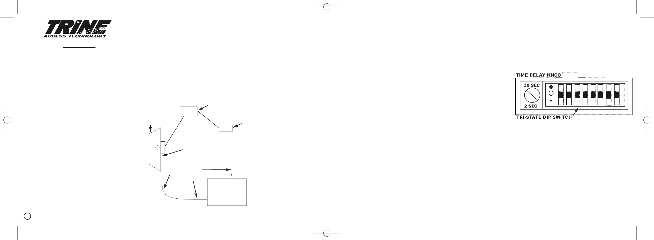
DOOR
STEPDOWN
TRANSFORMER
017TDC CONTROLLER
STRIKE/MAGNET
RECEPTIONIST
RECEPTIONIST
CAN BE
ANYWHERE
TOTAL WIRE USED: 20 FEET.
INSTALLS IN HALF THE TIME
The receiver has a voltage operating
range of 12V to 24V, AC or DC (wet).
When using a DC power source it’s
important to NOT cross the (+) and
(-) leads. Each receiver is clearly
marked for the power in and power
out terminals.
The auxiliary dry form “C” contacts
are rated 6-24 volts AC or DC at 1
amp - with a hermetically sealed
relay.
The 017TDC has a built-in time delay
feature with a range of 2-30 seconds.
This is used to time how long you
want the relay to remian open or
closed. This can be adjusted by sim-
ply turning the knob which is located
next to the dip switch.
GENERAL INFORMATION:
The remote controlled receiver is acti-
vated by an RF (radio frequency) sig-
nal. This signal is generated from a
handheld wireless transmitter model
(018-1), which is portable. When
used in structures that have a high
content of metal, the range will be
reduced from its established 150 feet
(line of sight). The receiver may be
placed in a ceiling or mounted on the
wall as long as the wire antenna is not
obstructed or laid against any metal
surface. The white antenna wire
should be kept exposed.
INSTALLATION:
Your 017TDC receiver is equipped
with a dip switch that offers 6561 dif-
ferent codes to reduce interference
from other wireless devices. In the
event of a false activation of the
receiver by another device, the codes
can be changed thereby eliminating
the false trigger. Simply remove the
cover on the unit to expose the
switches.
The diagram illustrates the eight (3)
position dip switch.
It is not recommended that all of the
switches are left in the same posi-
tion.
It is important to remember that
the dip switch setting in the o17TDC
must match the setting in the model
018-1 transmitter. With the dip
switches on both the receiver and
transmitter matching, the installation
is ready to begin.
C2000 (1) (2) (3) (4) (5)
Instruction Manual
017TDC Instructions.qxd 12/12/00 7:59 AM Page 1
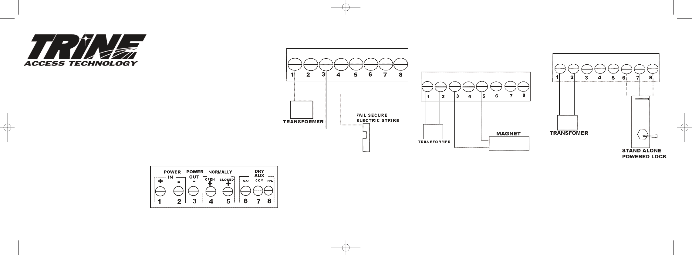
ELECTRIC STRIKE
NORMALLY OPEN
CIRCUIT USED
STAND ALONE
SELF POWER DEVICE
NORMALLY CLOSED OR NORMALLY OPEN
DRY CIRCUIT USED
POWER IN
1 - POSITIVE +
2 - NEGATIVE -
POWER OUT
3 - POWER -
4 - NORMALLY OPEN +
POWER IN
1 - POSITIVE +
2 - NEGATIVE -
POWER LOOP
6 - NORMALLY OPEN +
7 - COMMON -
8 - NORMALLY CLOSED+
(NOTE: SELECT ONE CONTACT)
The following diagrams show the cor-
rect wiring required for an electric
strike (normally open contact) and an
electro magnetic lock (normally
closed). This is simply an illustration
and its important to remember that
devices other than the ones illustrat-
ed can be used.
017TDC
CONTACT
TERMINAL
MARKINGS
FAIL SAFE ELECTRIC STRIKE
OR
ELECTRO MAGNETIC LOCK
NORMALLY CLOSED
CIRCUIT USED
POWER IN
1 - POSITIVE +
2 - NEGATIVE -
POWER OUT
3 - POWER -
5 - NORMALLY CLOSED +
(6) (7) (8 (9)
12-24 AC OR DC
Transformer is required
1440 FERRIS PLACE
BRONX, NY 10461
PH: 718-829-2332
FAX: 718-829-6405
www.trineonline.com
Section 15.21 Information to User
The users manual or instruction manual
for an intentional or unintentional radiator
shall caution the user that changes or
modifications not expressly approved by the
party responsible for compliance could void
the user’s authority to operate the equip-
ment.
017TDC Instructions.qxd 12/12/00 7:59 AM Page 2