Triple Plus NWLFD Flood detector of Water leakage security system User Manual Microsoft PowerPoint User s Manual NWL ENG
Triple Plus Flood detector of Water leakage security system Microsoft PowerPoint User s Manual NWL ENG
UserManual.wiki
>
Triple Plus
>
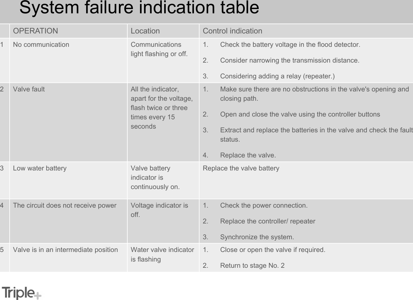
NWLFD User Manual
Users Manual
Navigation menu
Upload a User Manual
Namespaces
Wiki Guide
HTML
PDF
Info
Views
User Manual
Discussion / Help
Navigation