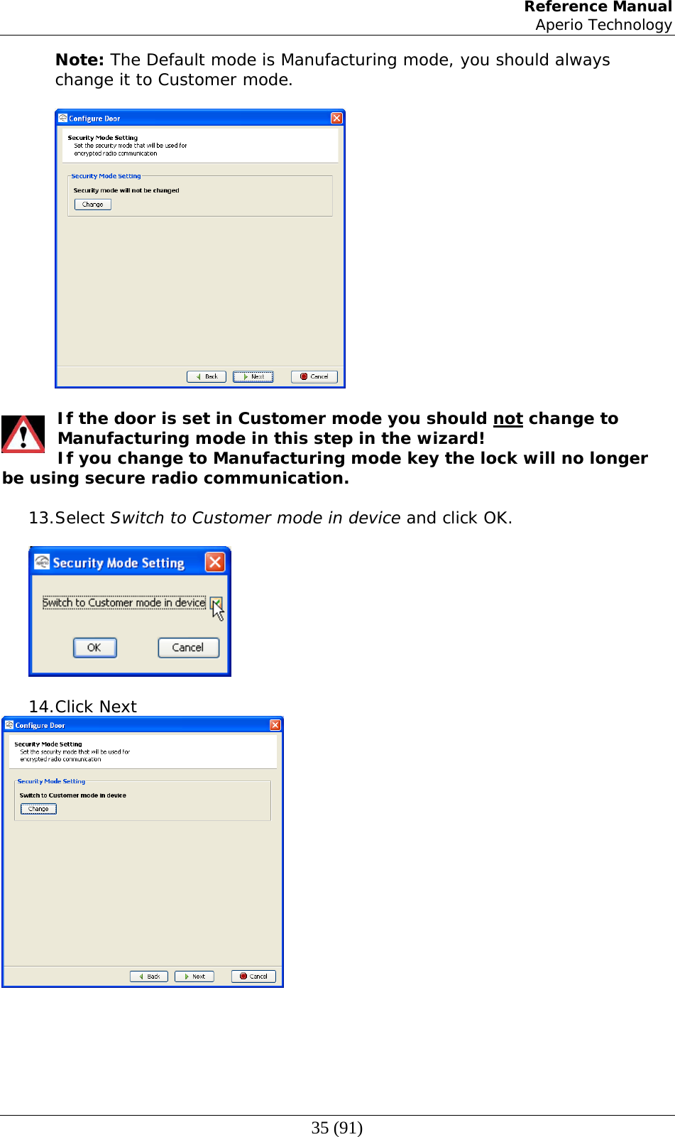
Tritech Technology 200300 TriBee USB User Manual
Tritech Technology AB TriBee USB
UserManual.wiki
>
Tritech Technology
>
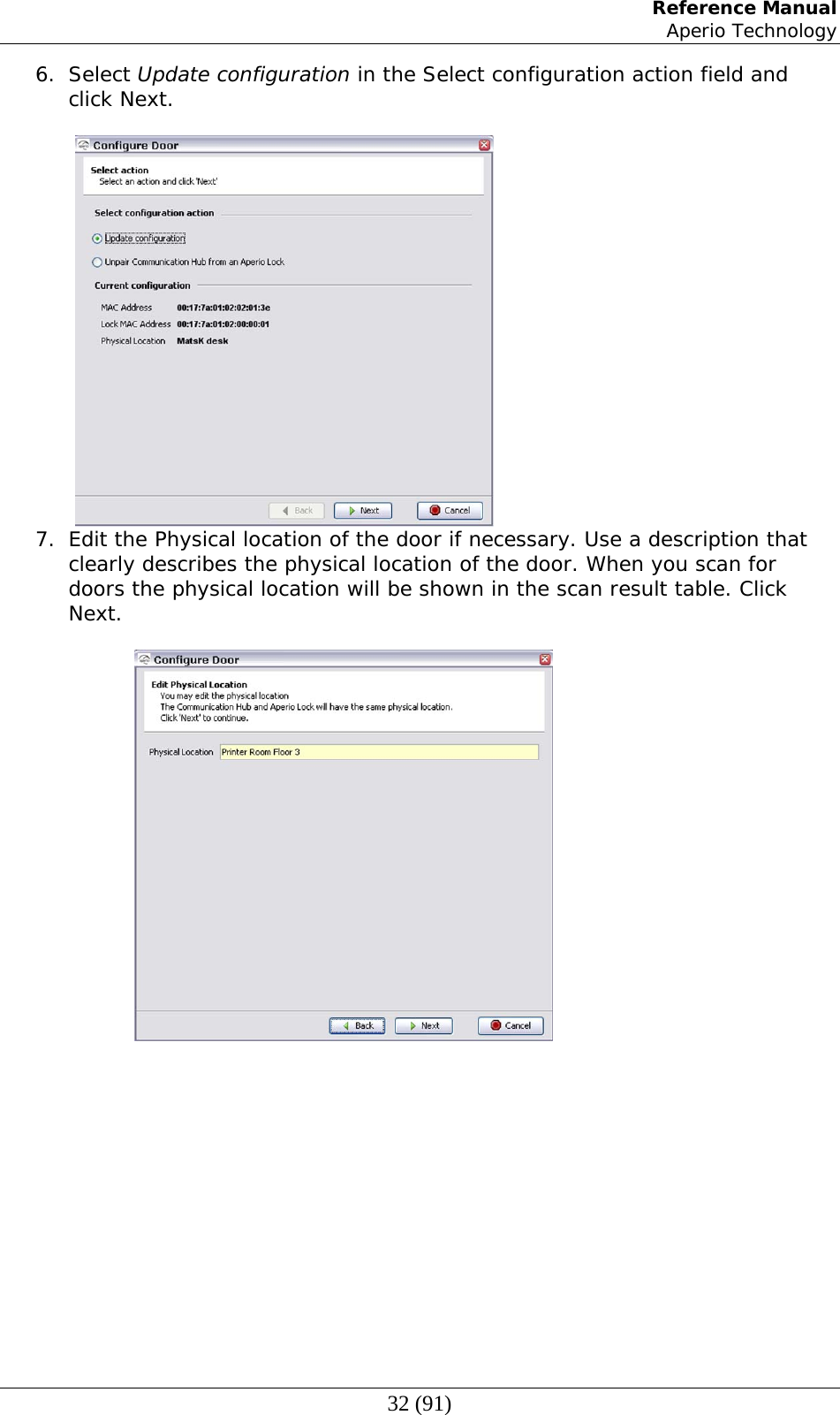
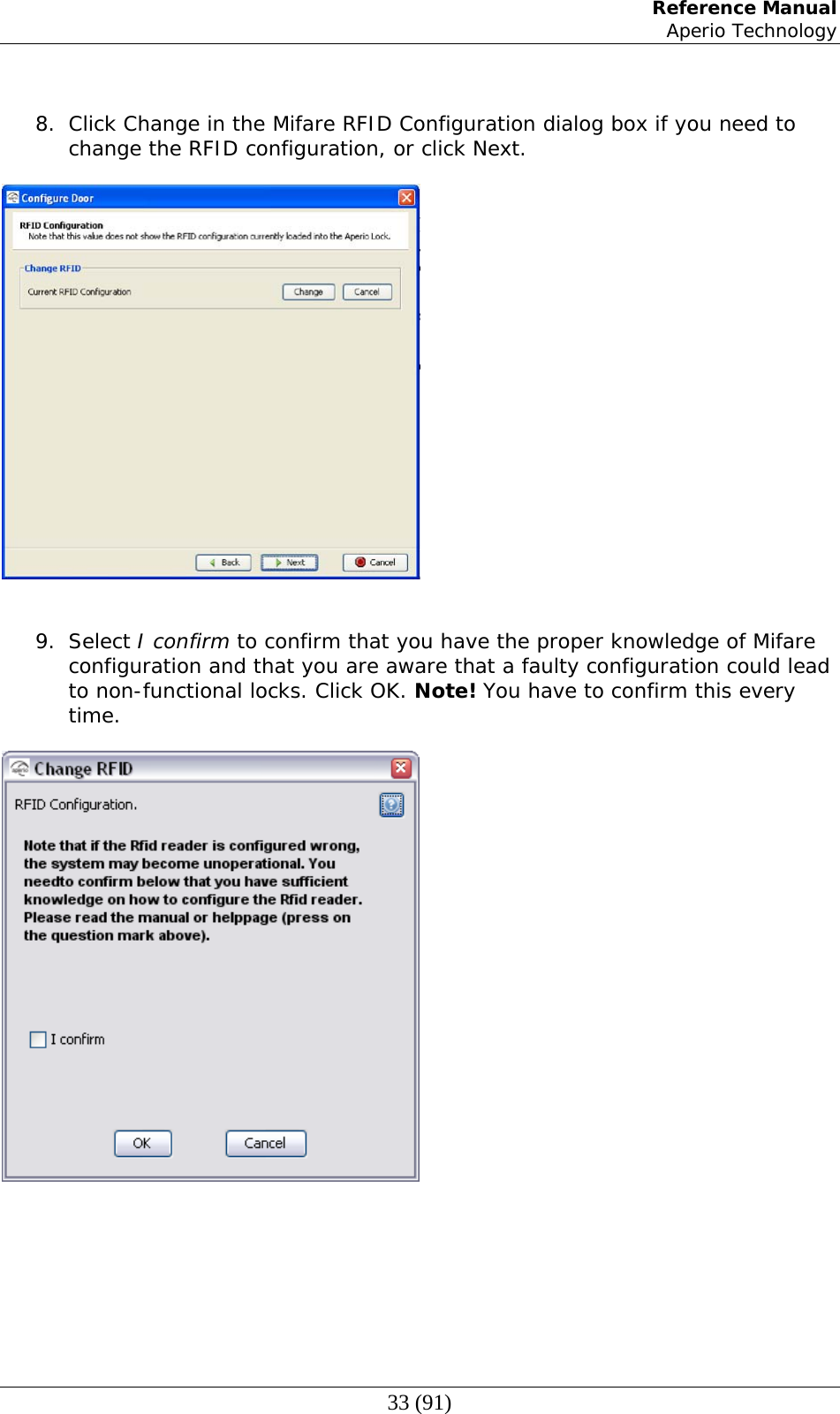
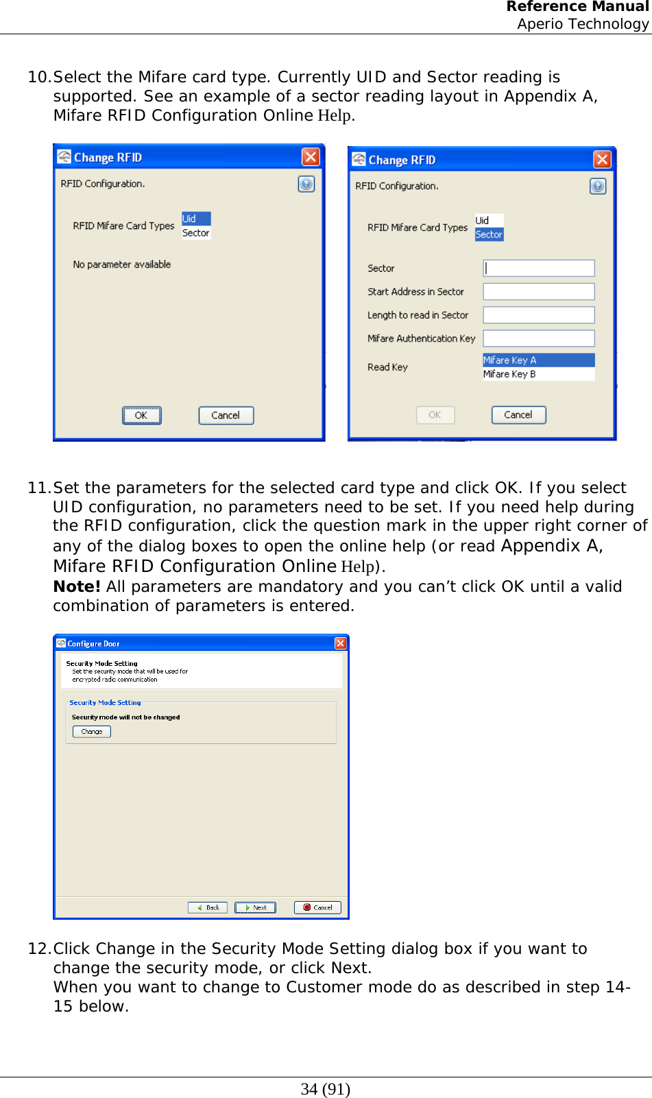
200300 User Manual
User Manual
Navigation menu
Upload a User Manual
Namespaces
Wiki Guide
HTML
PDF
Info
Views
User Manual
Discussion / Help
Navigation
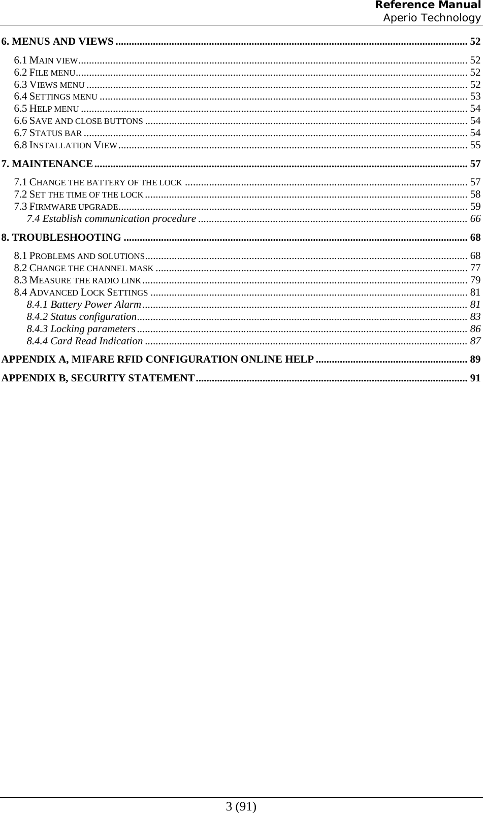
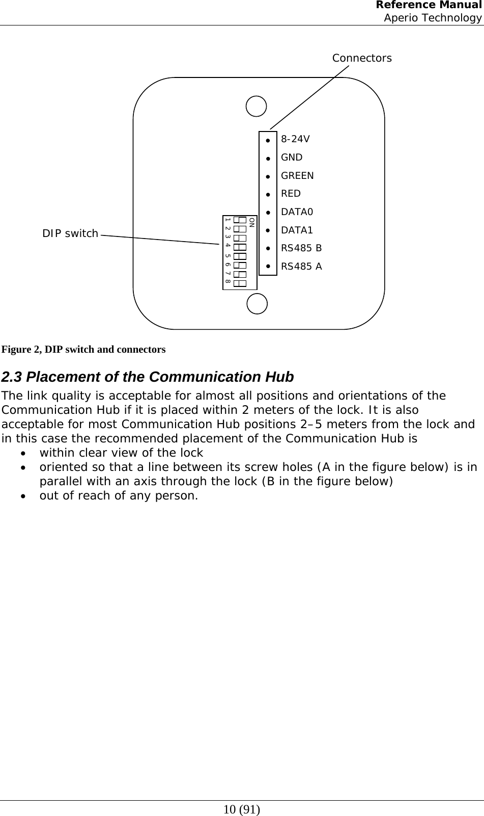
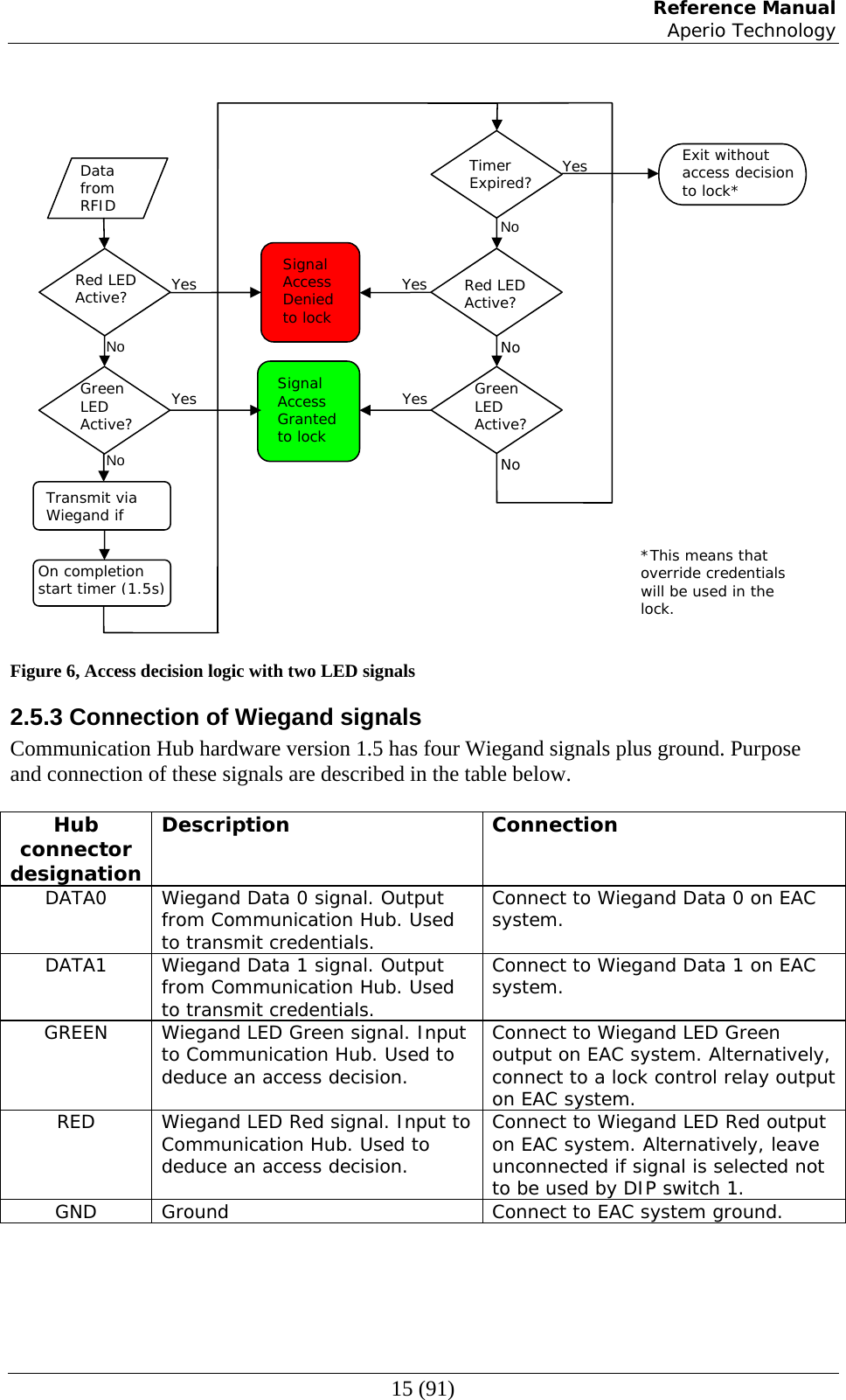
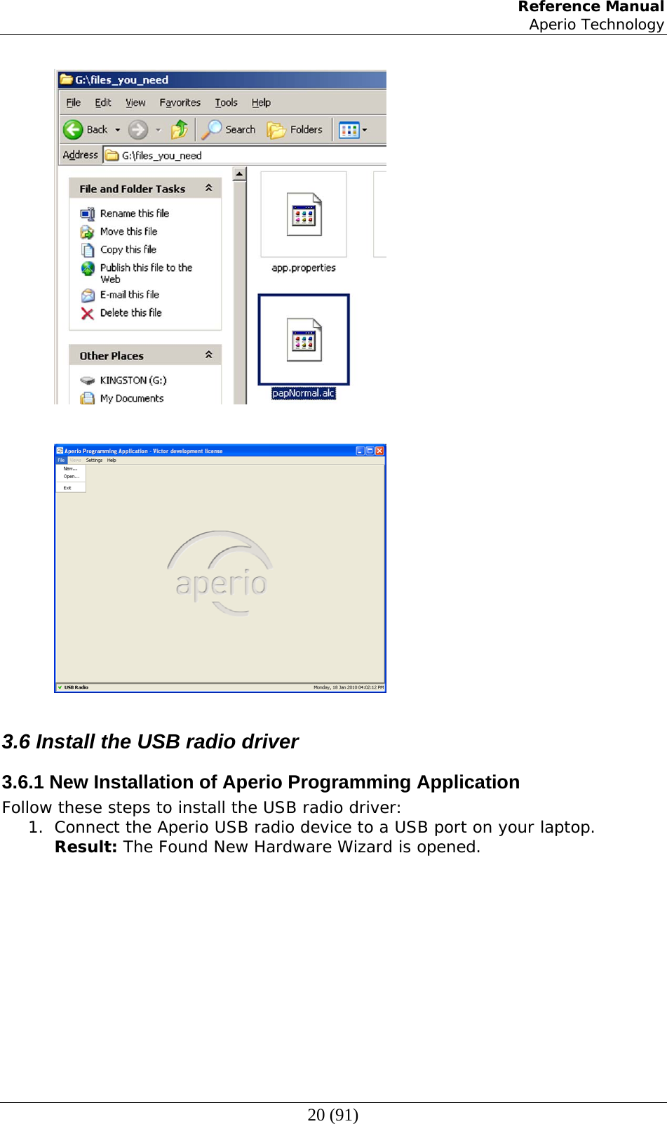
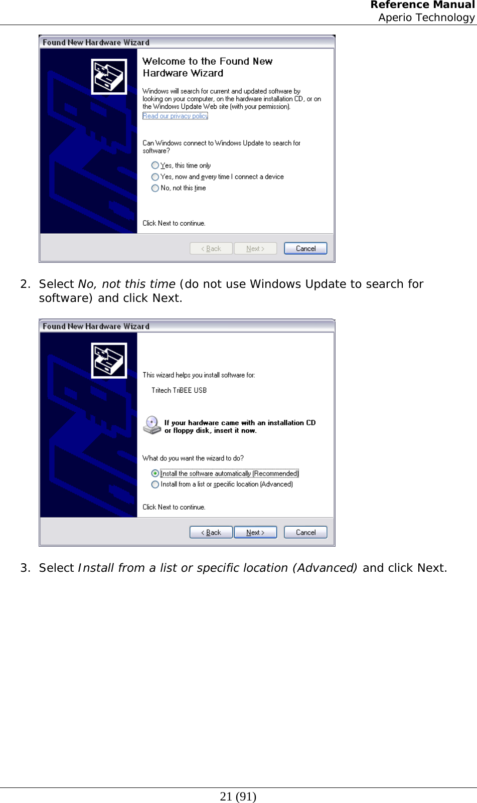
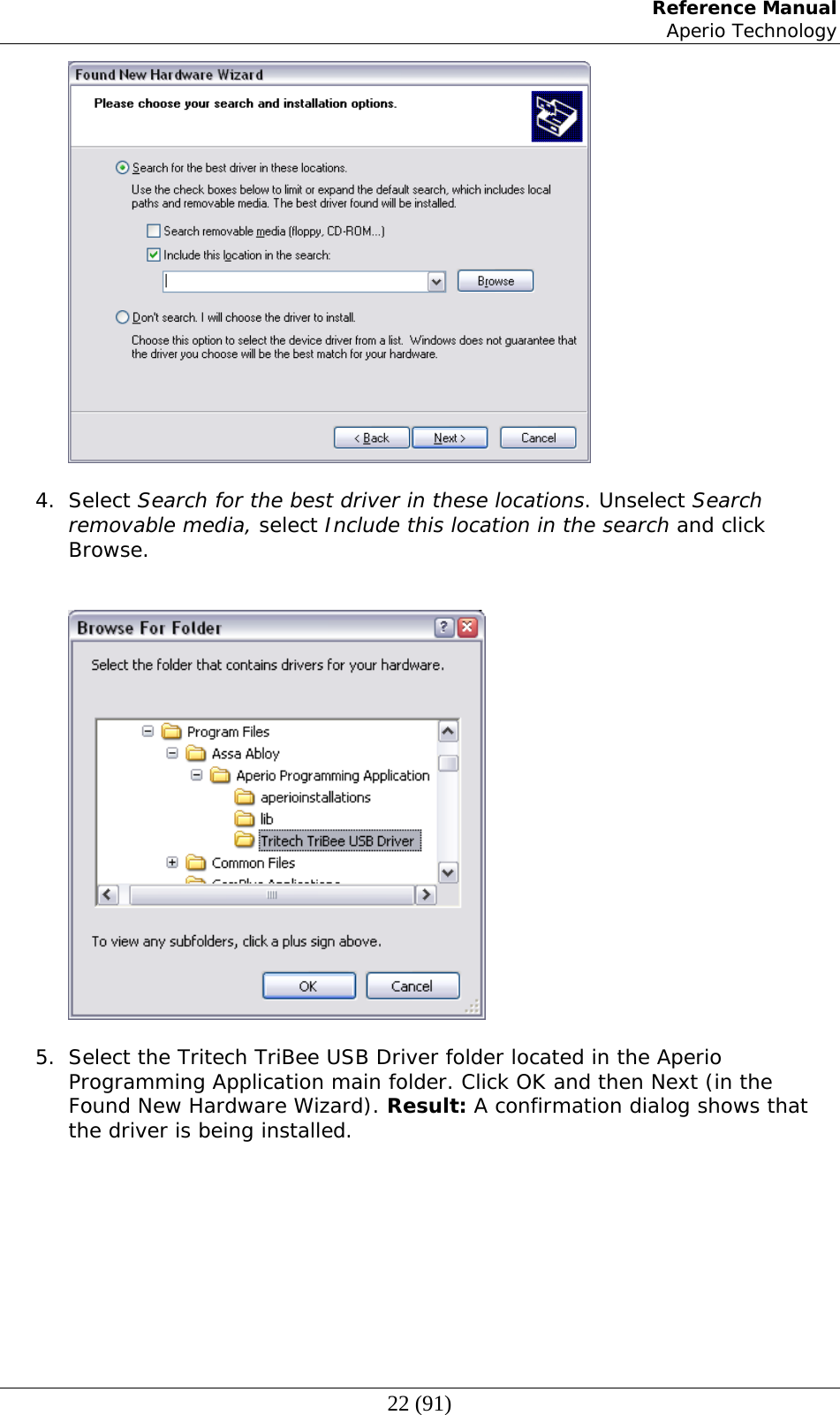
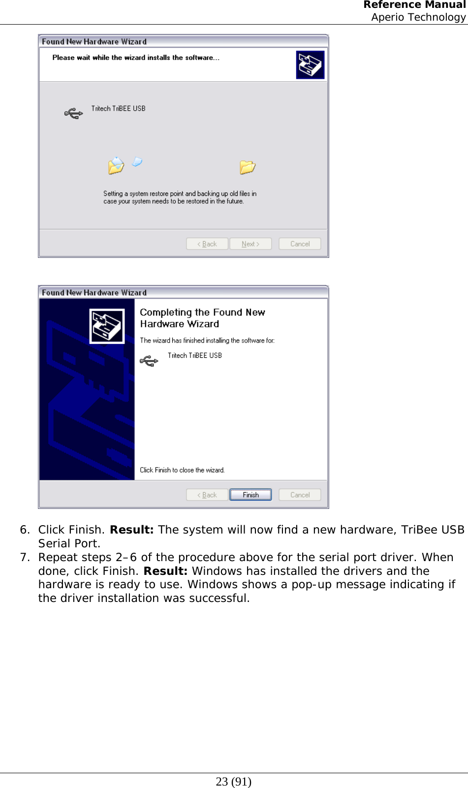
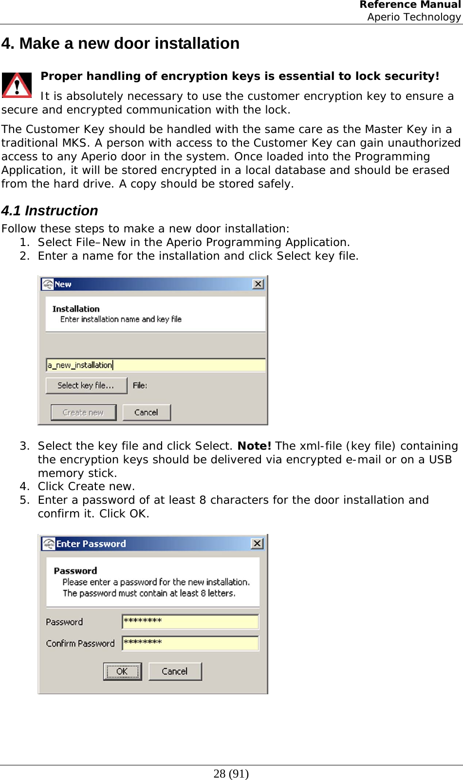
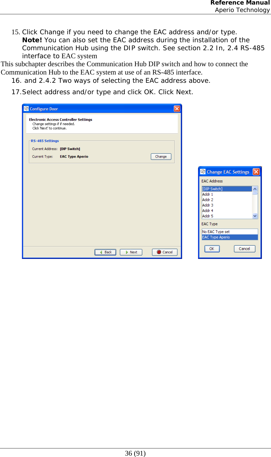
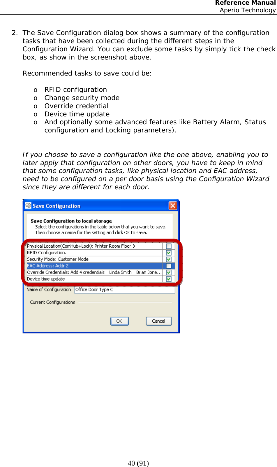
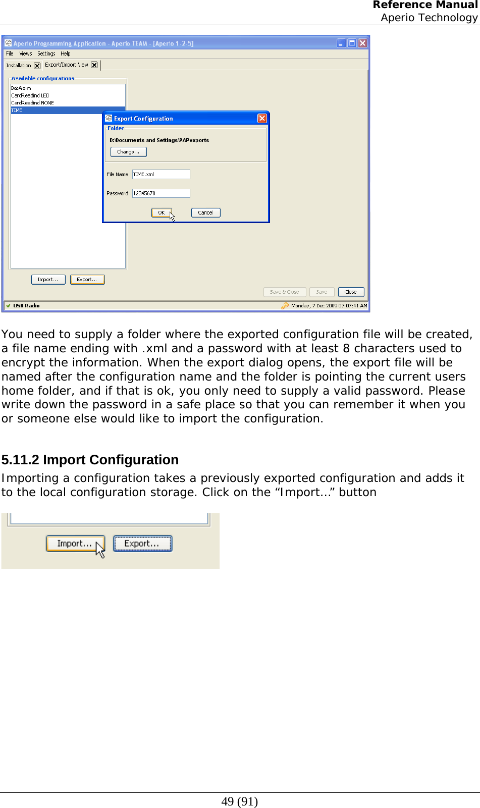
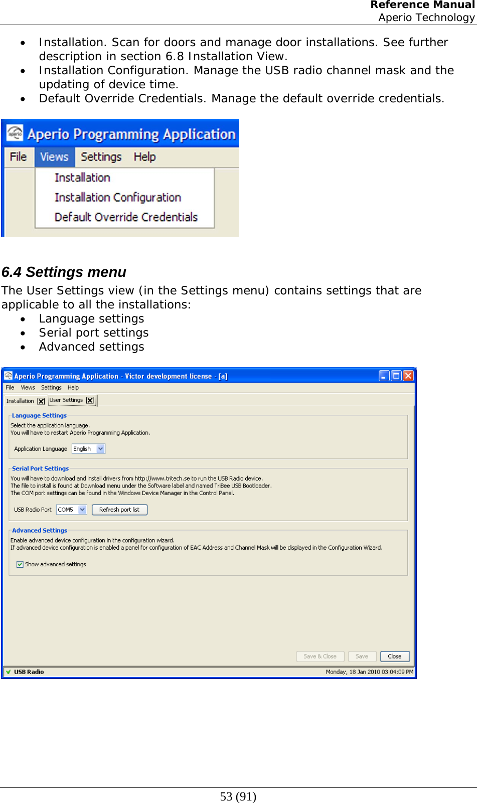
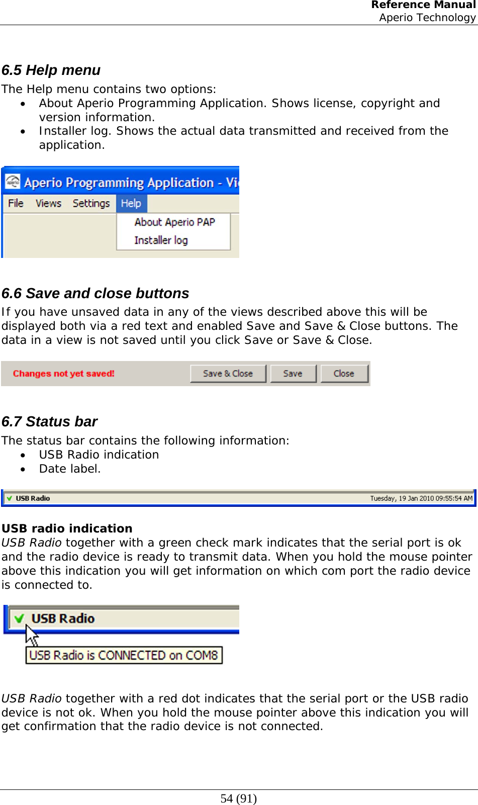
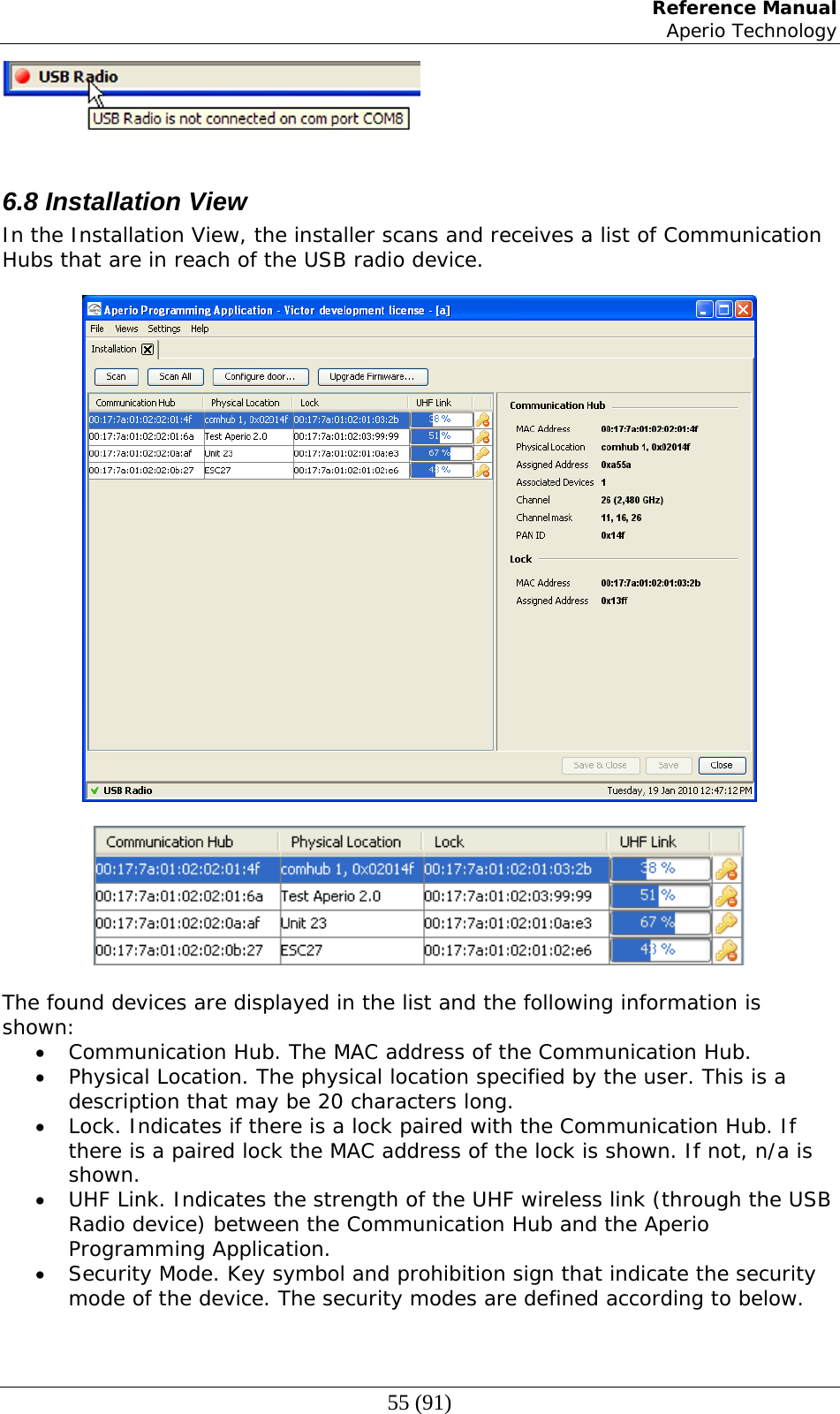
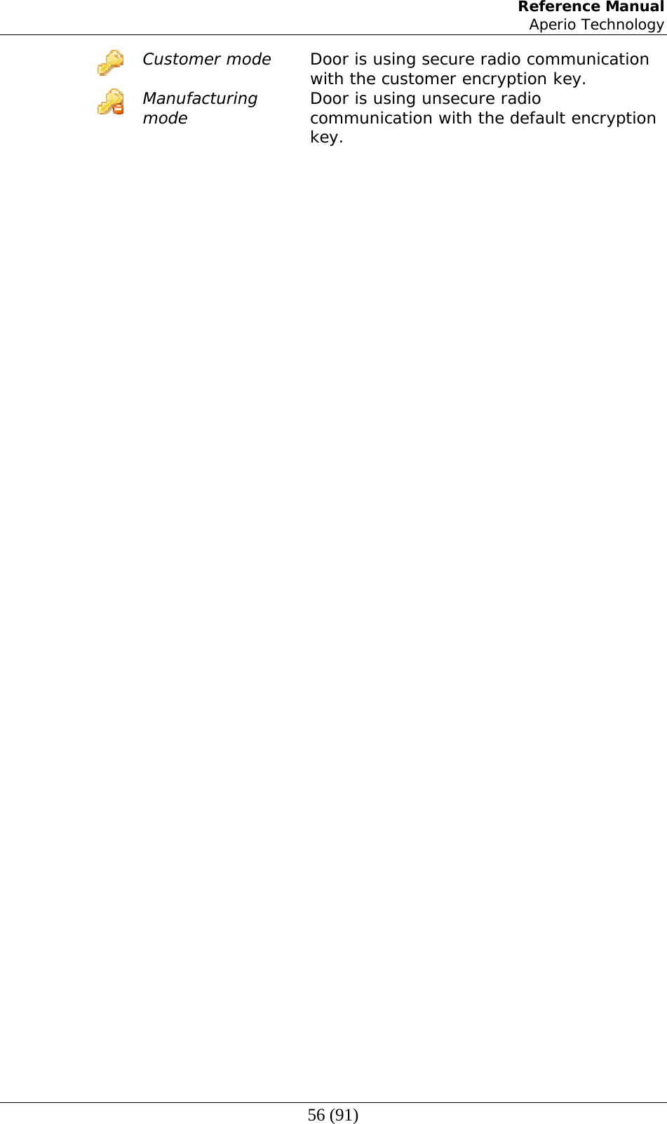
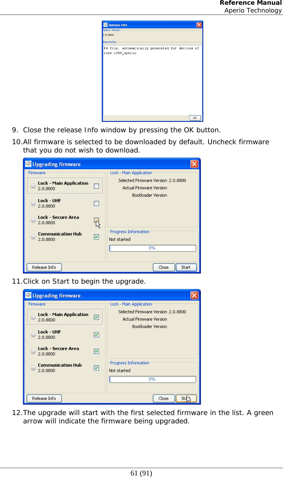
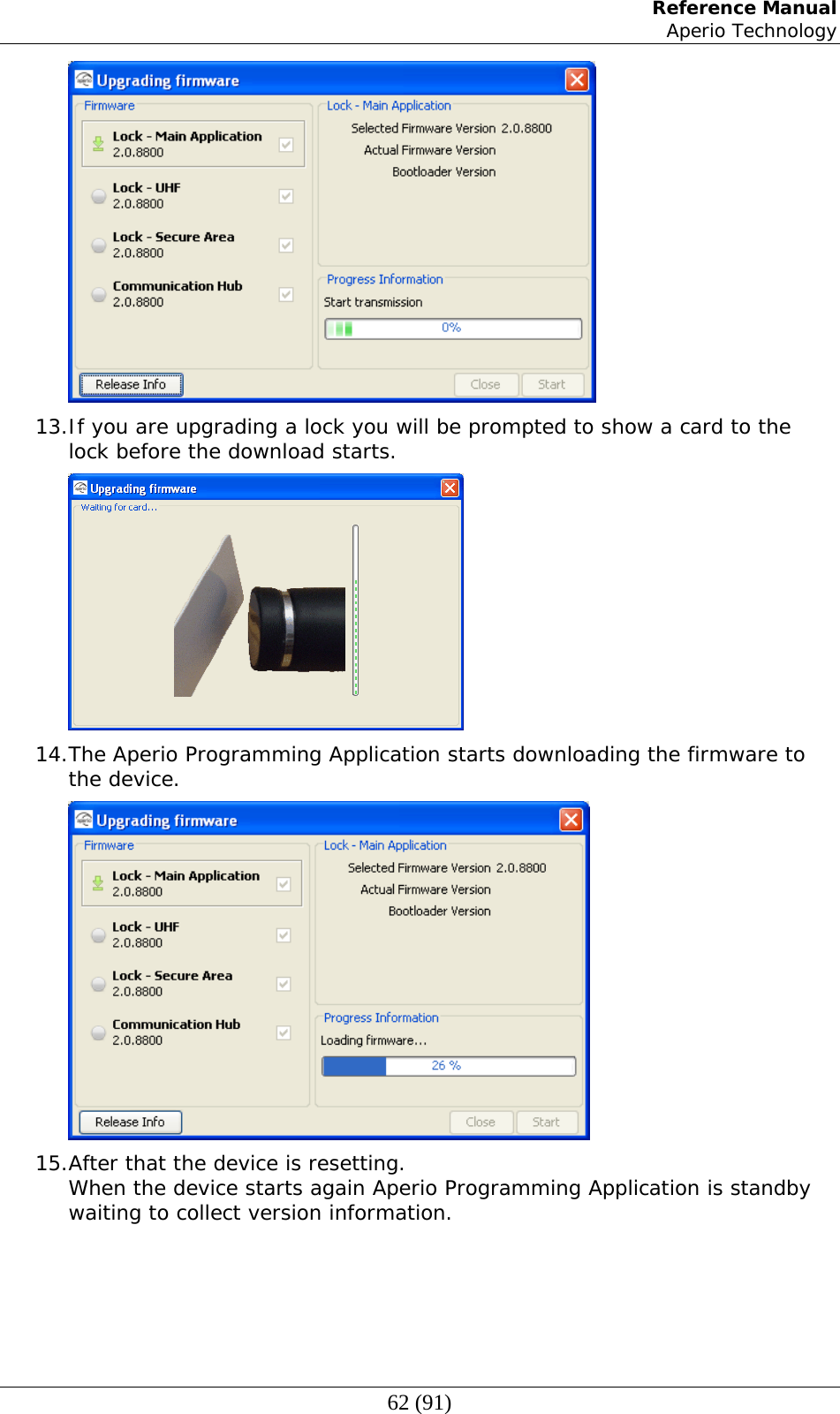
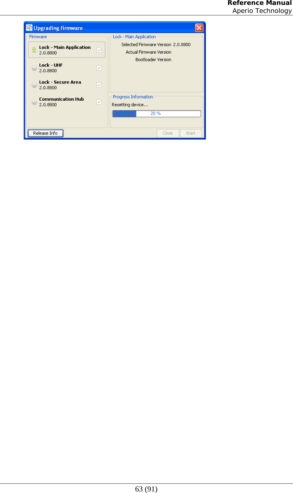
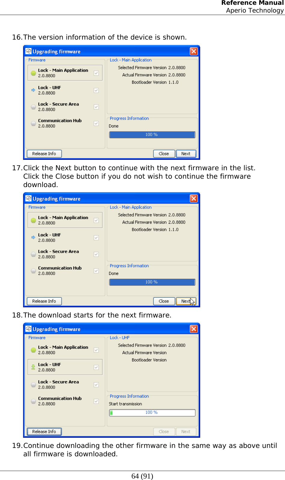
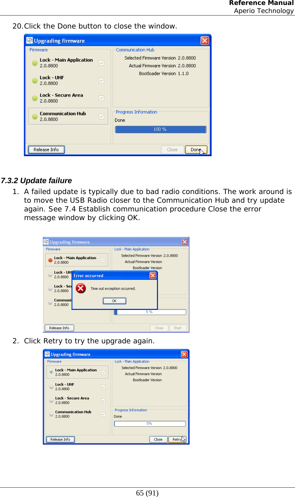
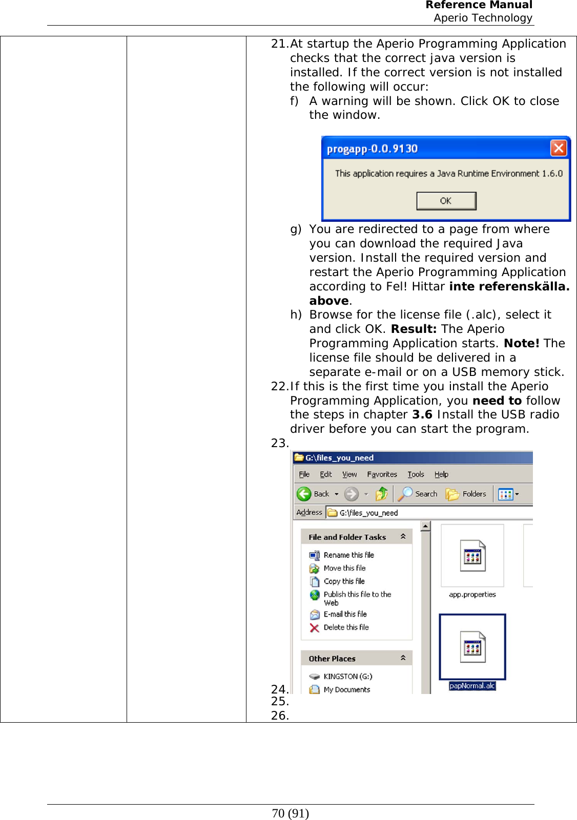
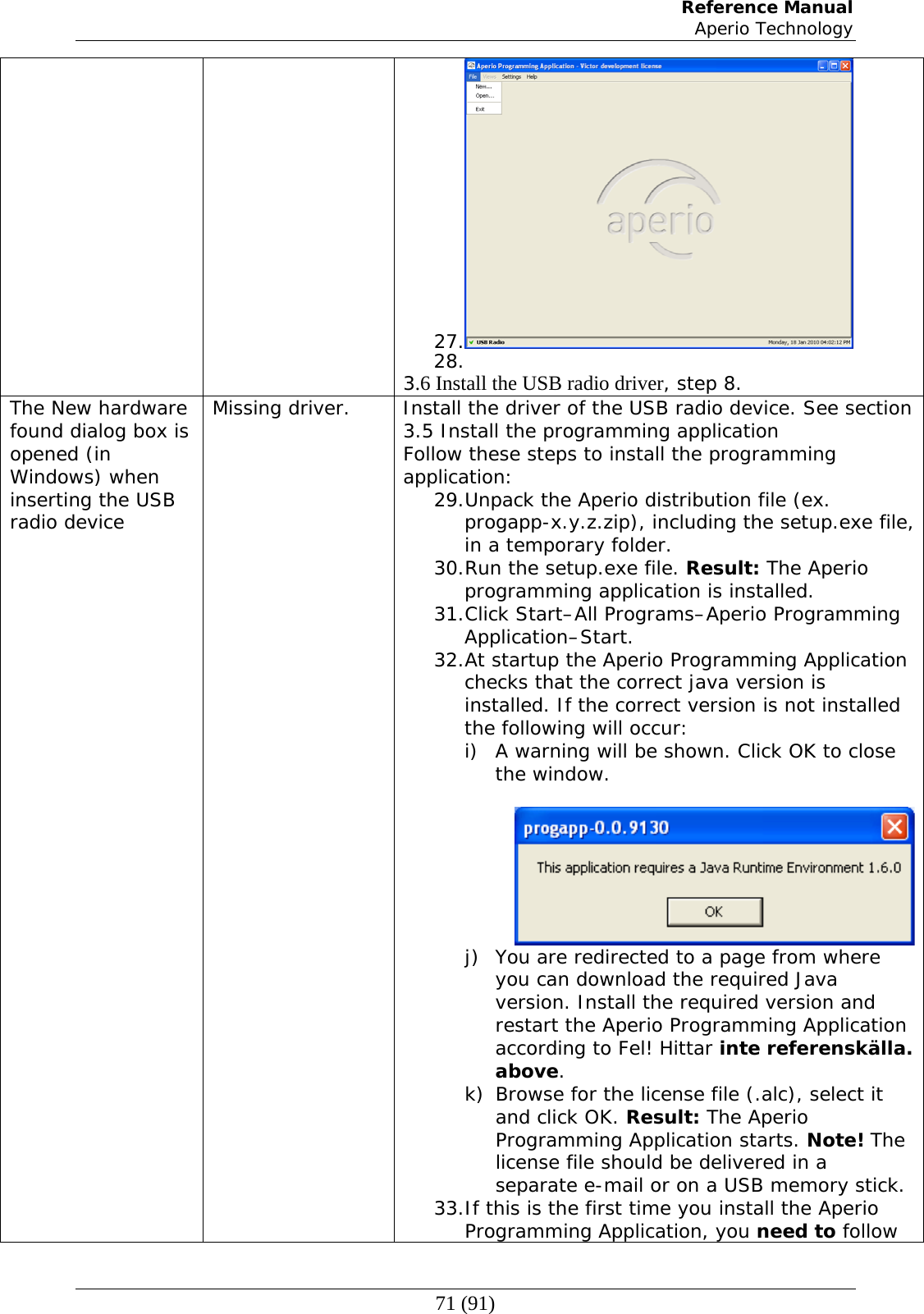
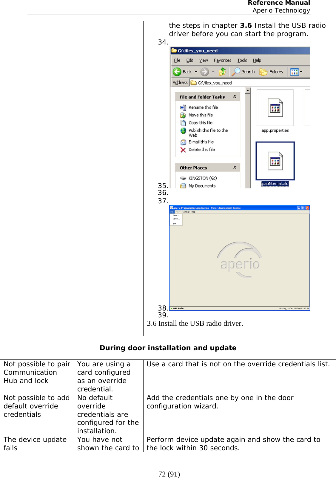
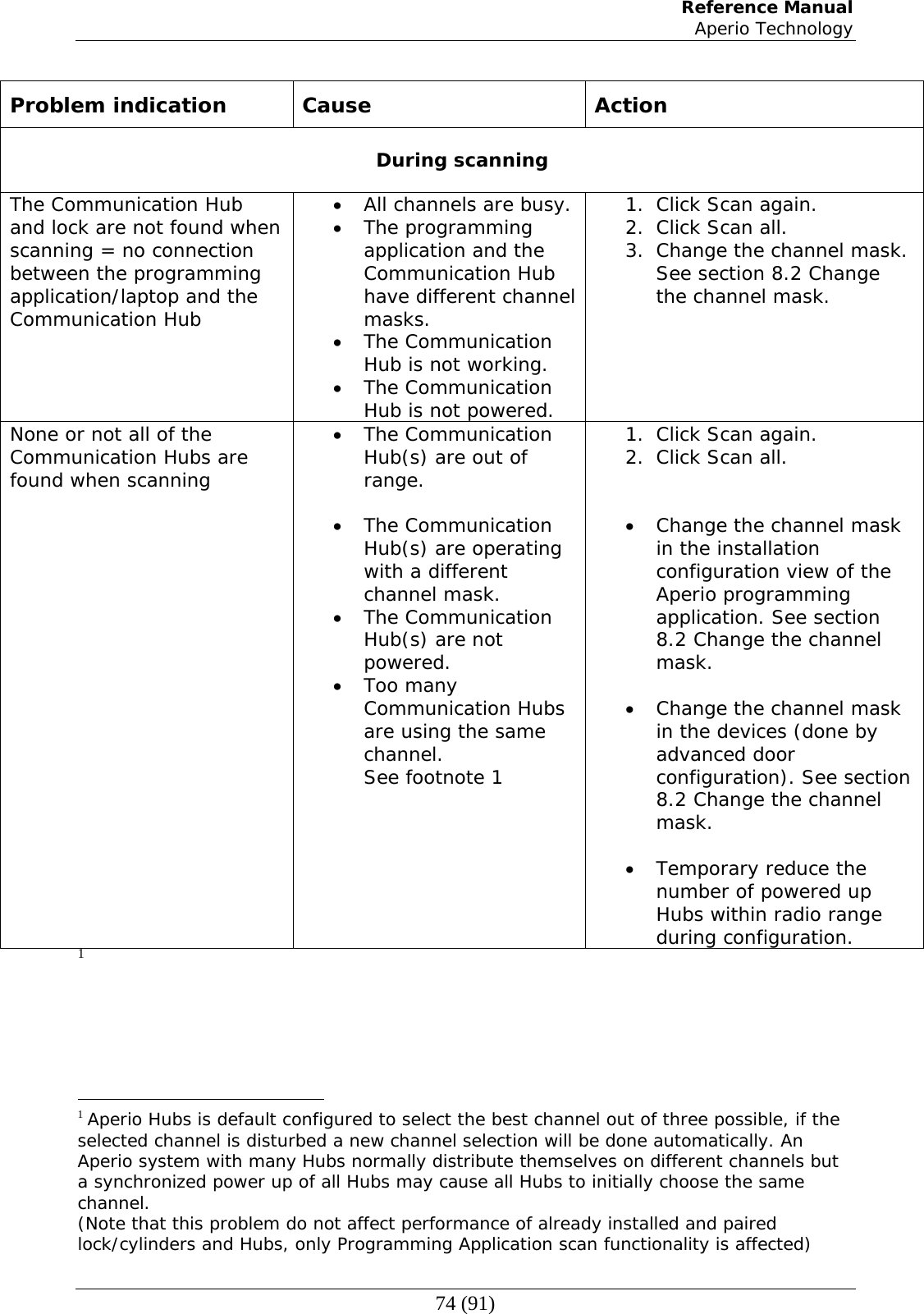
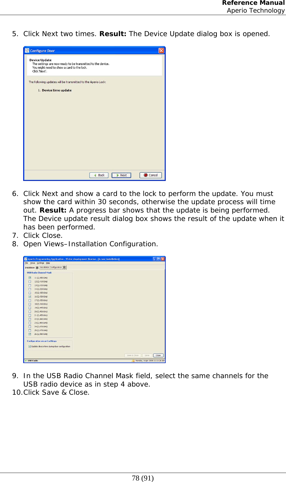
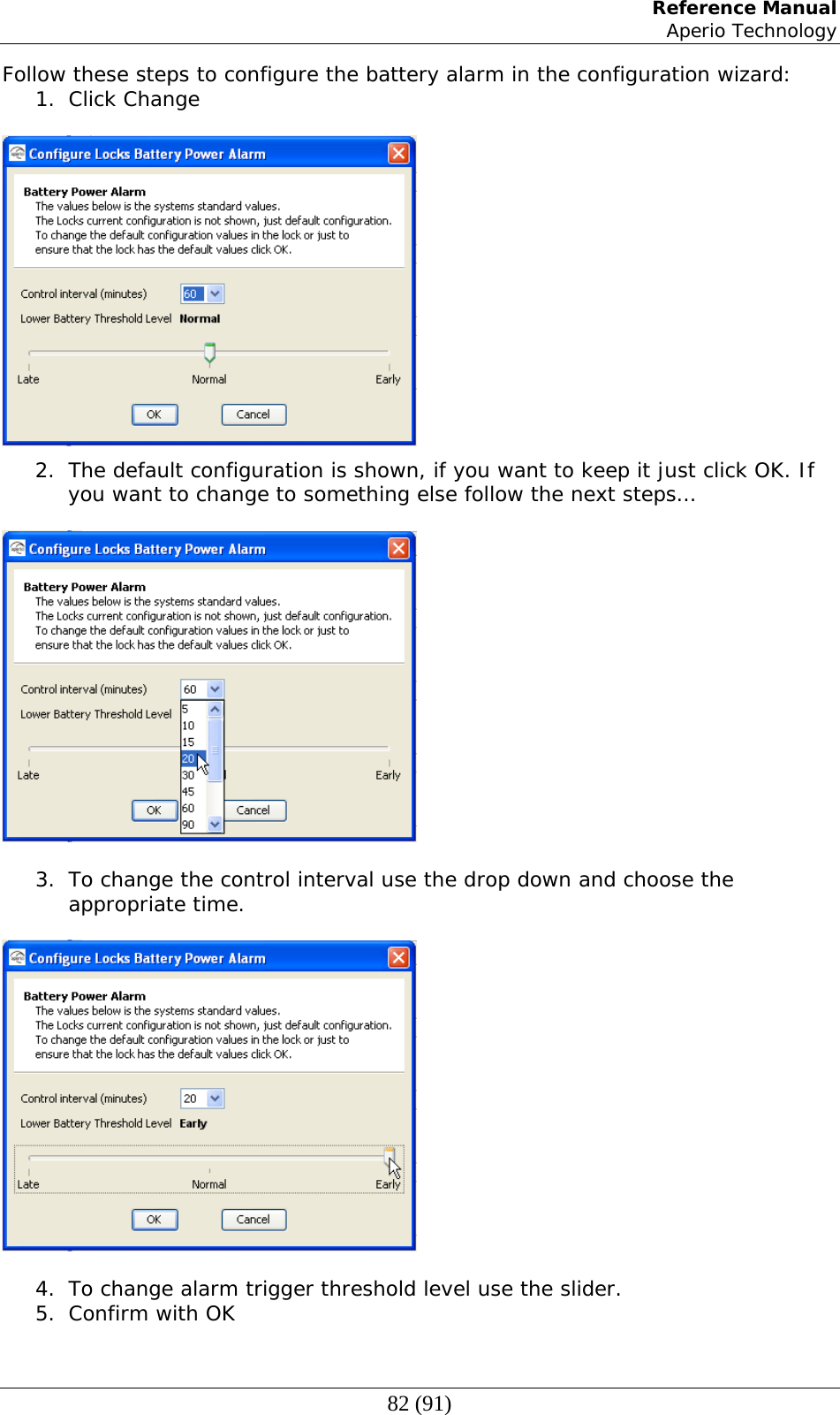
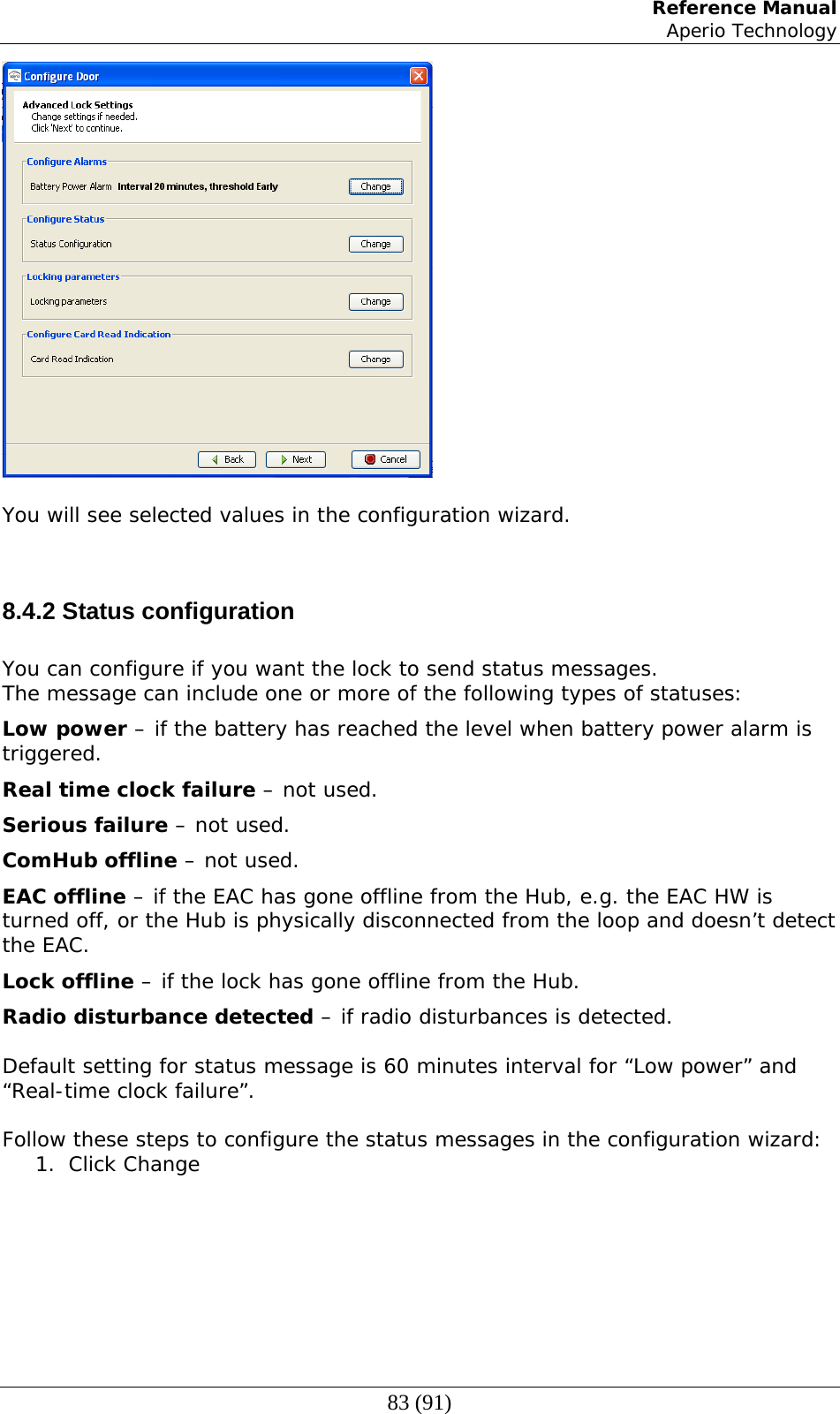
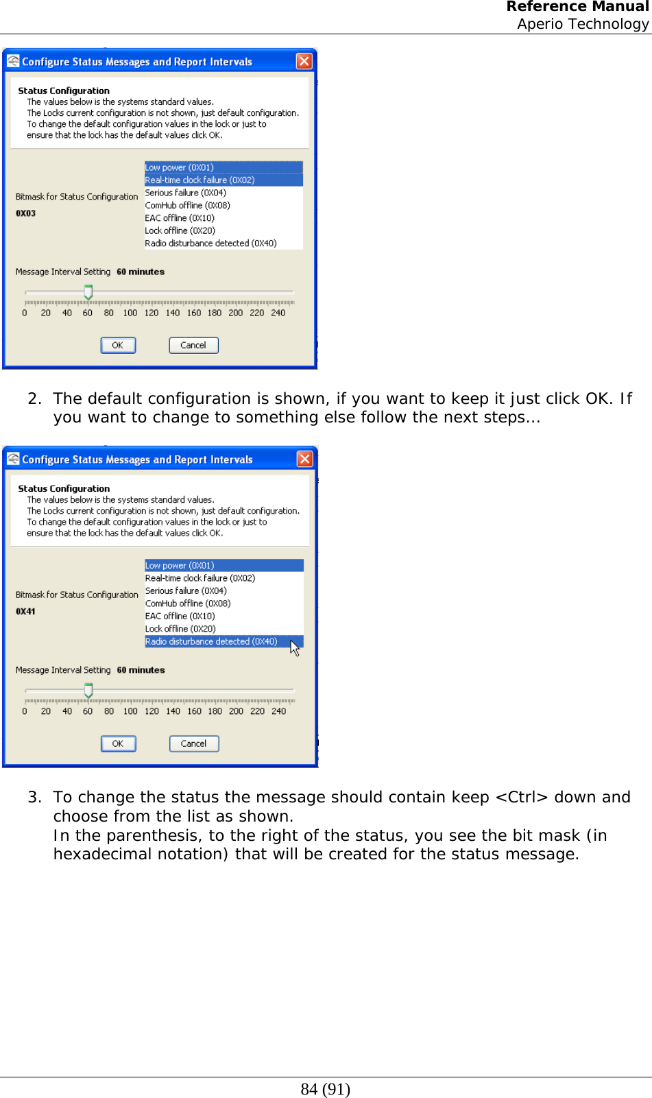
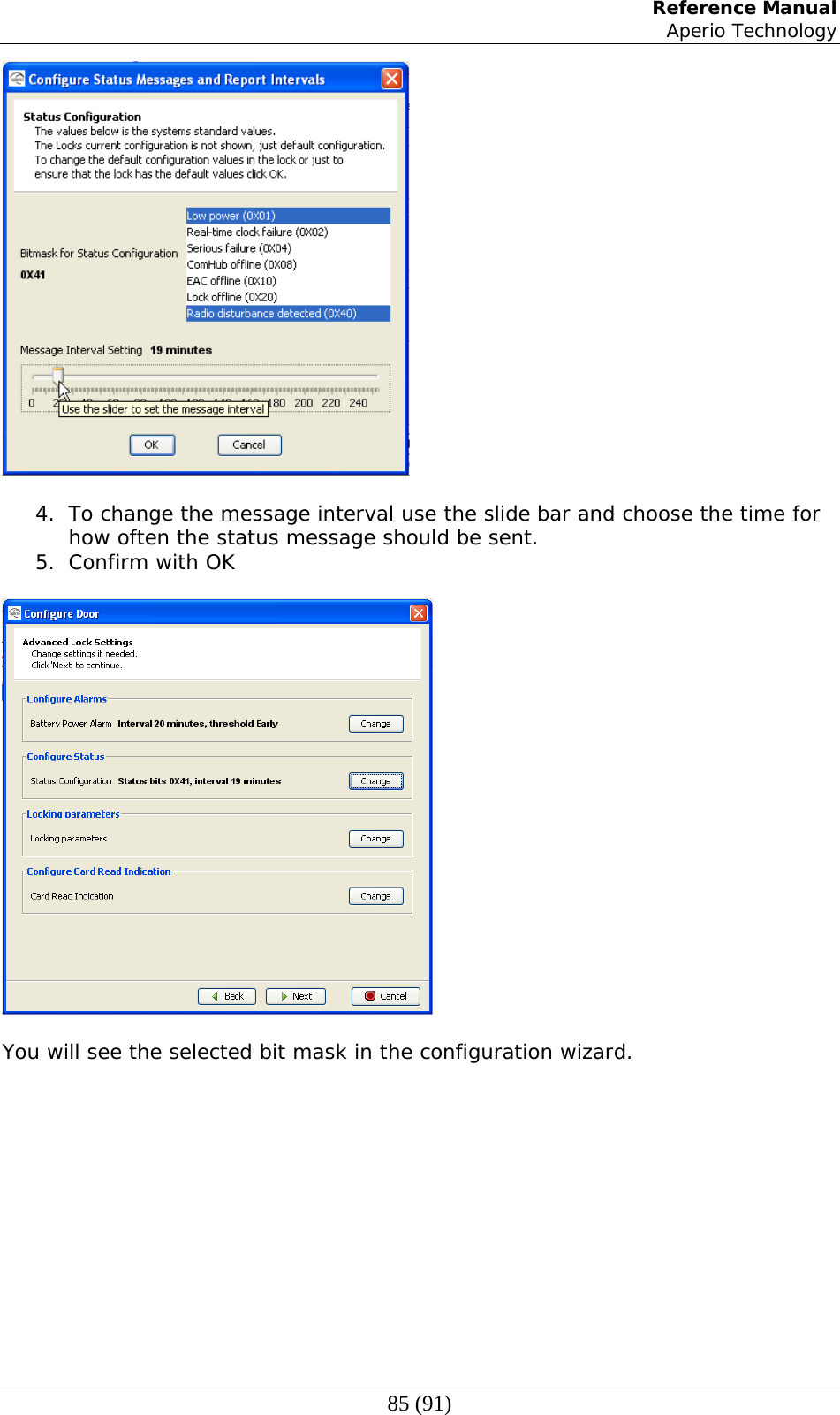
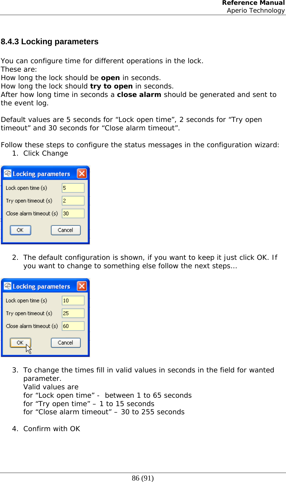
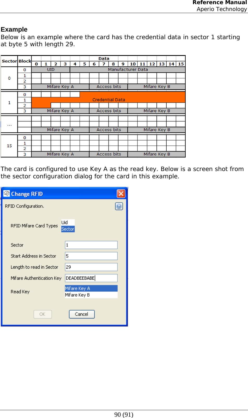
![Reference Manual Aperio Technology 14 (91) ON => Pulse width 40us, pulse interval 1000us. 3 Controls addition of parity bits on transmitted credentials. One even parity bit before and one odd parity bit after the actual credentials. OFF => Addition of parity is disabled. Credentials are transmitted as received. ON => Addition of parity bits is enabled. Note Transmitted credentials may include parity also if addition of parity is disabled in the Hub Wiegand EAC interface component. This since parity bits, if used, typically are included already on the card. 4 Controls byte order of transmitted credentials. OFF => The byte order is left as is. ON => The byte order is reversed compared to what is received as input to the Hub Wiegand EAC interface component. Note 1 This setting is ignored if the credential length does not make up complete bytes. Note 2 The byte order received as input to the Hub Wiegand EAC interface component in the case of a 32 bit MIFARE UID credential is UID[3], UID[2], UID[1], UID[0]. This means that the byte order is already reversed earlier in the chain compared to the order specified in RFID interface standard ISO 14443-3. 5 Reserved for future use. Set to OFF. 6 Not applicable for Wiegand. Set to OFF. 7 Not applicable for Wiegand. Set to OFF. 8 Not applicable for Wiegand. Set to OFF. 2.5.2 LED input signals and access decision The flowcharts below show how the LED input signals are used to derive an access decision. Two variants are depicted. Which variant that is used is selected by DIP switch 1. Figure 5, Access decision logic with single LED signal Data from RFID Green LED Active? Transmit via Wiegand if On completion start timer (1.5s) Signal Access Denied to lock Signal Access Granted to lock Timer Expired? Green LED Active? Yes Yes Yes No No No](https://usermanual.wiki/Tritech-Technology/200300/User-Guide-1378320-Page-14.png)