Tritech Technology 200300 TriBee USB User Manual
Tritech Technology AB TriBee USB
User Manual

Reference Manual
Aperio
Technology
Document: AAWL-135
Revision: PE7
Date: 2010-10-27

Reference Manual
Aperio Technology
2 (91)
Contents
REVISION HISTORY ......................................................................................................................................... 4
REGULATORY INFORMATION REGARDING THE APERIO USB RADIO DONGLE ......................... 5
COMPLIANCE ...................................................................................................................................................... 5
ACCORDING TO FCC15.105 (B) INFORMATION TO THE USER .............................................................................. 5
ACCORDING TO FCC15.247: ............................................................................................................................... 5
INTRODUCTION ................................................................................................................................................. 6
PURPOSE AND INTENDED USER OF THIS MANUAL ................................................................................................ 6
1. SYSTEM OVERVIEW ..................................................................................................................................... 7
1.1 SYSTEM DESCRIPTION ................................................................................................................................... 7
1.2 SYSTEM COMPONENTS ................................................................................................................................... 8
2. INSTALL THE COMMUNICATION HUB .................................................................................................. 9
2.1 EAC INTERFACE VARIANTS ........................................................................................................................... 9
2.2 INSTALLATION PROCEDURE ........................................................................................................................... 9
2.3 PLACEMENT OF THE COMMUNICATION HUB ............................................................................................... 10
2.4 RS-485 INTERFACE TO EAC SYSTEM .......................................................................................................... 11
2.4.1 RS-485 DIP switch description ........................................................................................................... 11
2.4.2 Two ways of selecting the EAC address ............................................................................................. 11
2.4.3 Connection of the RS-485 bus ............................................................................................................. 12
2.5 WIEGAND INTERFACE TO EAC SYSTEM ....................................................................................................... 13
2.5.1 Wiegand DIP switch description ........................................................................................................ 13
2.5.2 LED input signals and access decision ............................................................................................... 14
2.5.3 Connection of Wiegand signals .......................................................................................................... 15
2.5.4 Configuration considerations ............................................................................................................. 16
2.6 COMMUNICATION HUB LED INDICATION .................................................................................................... 16
2.7 LOCK NORMAL OPERATION LED INDICATION ............................................................................................. 17
2.8 LOCK MAINTENANCE LED INDICATION ....................................................................................................... 17
2.9 LOCK SELF TEST LED INDICATION .............................................................................................................. 18
3. INSTALL THE PROGRAMMING APPLICATION .................................................................................. 19
3.1 COMPUTER SPECIFICATIONS ........................................................................................................................ 19
3.2 FILES NEEDED FOR THE INSTALLATION ........................................................................................................ 19
3.5 INSTALL THE PROGRAMMING APPLICATION ................................................................................................. 19
3.6 INSTALL THE USB RADIO DRIVER ............................................................................................................... 20
3.6.1 New Installation of Aperio Programming Application ....................................................................... 20
3.6.2 Update the driver in an existing Aperio Programming Application ................................................... 24
4. MAKE A NEW DOOR INSTALLATION ................................................................................................... 28
4.1 INSTRUCTION .............................................................................................................................................. 28
5. MAKE THE FIRST CONFIGURATION OF A DOOR INSTALLATION .............................................. 29
5.1 PURPOSE OF THE FIRST CONFIGURATION ..................................................................................................... 29
5.2 SCAN FOR APERIO LOCKS ............................................................................................................................ 29
5.3 UPDATE THE DOOR CONFIGURATION ........................................................................................................... 31
5.4 SET THE OVERRIDE CREDENTIALS ............................................................................................................... 37
5.5 SET THE ADVANCED SETTINGS .................................................................................................................... 38
5.6 SAVE THE CONFIGURATION TO LOCAL STORAGE ......................................................................................... 39
5.7 PERFORM THE DEVICE UPDATE .................................................................................................................... 42
5.8 CHANGING THE SECURITY MODE ................................................................................................................ 44
5.9 HOW TO APPLY A STORED CONFIGURATION TO A DOOR .............................................................................. 46
5.10 TEST AFTER THE FIRST CONFIGURATION .................................................................................................... 48
5.11 IMPORT AND EXPORT CONFIGURATIONS .................................................................................................... 48
5.11.1 Export Configuration ........................................................................................................................ 48
5.11.2 Import Configuration ........................................................................................................................ 49

Reference Manual
Aperio Technology
3 (91)
6. MENUS AND VIEWS .................................................................................................................................... 52
6.1 MAIN VIEW .................................................................................................................................................. 52
6.2 FILE MENU ................................................................................................................................................... 52
6.3 VIEWS MENU ............................................................................................................................................... 52
6.4 SETTINGS MENU .......................................................................................................................................... 53
6.5 HELP MENU ................................................................................................................................................. 54
6.6 SAVE AND CLOSE BUTTONS ......................................................................................................................... 54
6.7 STATUS BAR ................................................................................................................................................ 54
6.8 INSTALLATION VIEW ................................................................................................................................... 55
7. MAINTENANCE ............................................................................................................................................ 57
7.1 CHANGE THE BATTERY OF THE LOCK .......................................................................................................... 57
7.2 SET THE TIME OF THE LOCK ......................................................................................................................... 58
7.3 FIRMWARE UPGRADE ................................................................................................................................... 59
7.4 Establish communication procedure ..................................................................................................... 66
8. TROUBLESHOOTING ................................................................................................................................. 68
8.1 PROBLEMS AND SOLUTIONS ......................................................................................................................... 68
8.2 CHANGE THE CHANNEL MASK ..................................................................................................................... 77
8.3 MEASURE THE RADIO LINK .......................................................................................................................... 79
8.4 ADVANCED LOCK SETTINGS ....................................................................................................................... 81
8.4.1 Battery Power Alarm .......................................................................................................................... 81
8.4.2 Status configuration ............................................................................................................................ 83
8.4.3 Locking parameters ............................................................................................................................ 86
8.4.4 Card Read Indication ......................................................................................................................... 87
APPENDIX A, MIFARE RFID CONFIGURATION ONLINE HELP ......................................................... 89
APPENDIX B, SECURITY STATEMENT ...................................................................................................... 91

Reference Manual
Aperio Technology
4 (91)
Revision history
Rev Date Changes
A 2009-09-29 First official version (for Aperio SW release 1.2.2).
B 2009-11-16 Updated for Aperio SW release 1.2.4.
• Added notes on customer key handling.
• Added “card read” and “error in lock” to “Lock LED indications”.
• Added lock maintenance and POST LED indications.
• “Change the battery of the lock” shall be covered by product
manuals, contents replaced by some Aperio general hints.
• “Advanced lock settings” / “Battery power alarm” updated.
• Release artifact names changed. Project names Victor and Breughel
replaced by product names C100 and E100 respectively.
C 2009-12-17 Updated for Aperio SW release 1.2.5.
• Added Card Read Indication configuration.
• Added Export/Import configuration from/to file – the old “export” is
now called “save to local storage”.
• Added battery low/critical to “Lock LED indications”, also changed
color of programming blink to yellow, removed FW upgrade blinks,
added error indication for battery not accepted as new.
D 2010-03-18 Updated for Aperio SW release 2.0.0 (Programming Application
1.3.8717).
• Description of RS-485 address selection by use of DIP switch in the
Communication Hub is improved.
• Updated for new Security Mode handling.
• Corrections after review by Stefan Widing
PE1 2010-04-28 • Updated with new firmware download handling.
• Override Credentials changed to be done using saved configuration.
• New Java installation procedure.
PE2 2010-04-30 • Updated after review
PE3 2010-05-04 • Updated with information in ATN-001
PE4 2010-05-26 • Changed name to Reference Manual. Addressed feedback from
Market Regions
PE5 2010-10-05 Added Wiegand interface description for the Communication Hub.
Modified figure Aperio technology overview. Hub voltage is TBD.
PE6 2010-10-07 Fixed TBDs about Hub voltage.
PE7 2010-10-27 Added regulatory information

Reference Manual
Aperio Technology
5 (91)
Regulatory information regarding the Aperio USB Radio
dongle
Compliance
This device complies with Part 15 of the FCC Rules and with RSS-210 of Industry
Canada.
Operation is subject to the following two conditions:
1. this device may not cause harmful interference, and
2. this device must accept any interference received, including interference
that may cause undesired operation.
Changes or modifications made to this equipment not expressly approved by
Tritech Technology AB may void the FCC authorization to operate this equipment.
According to FCC15.105 (b) Information to the user
This equipment has been tested and found to comply with the limits for a Class B
digital device, pursuant to part 15 of the FCC Rules. These limits are designed to
provide reasonable protection against harmful interference in a residential
installation. This equipment generates, uses and can radiate radio frequency
energy and, if not installed and used in accordance with the instructions, may
cause harmful interference to radio communications. However, there is no
guarantee that interference will not occur in a particular installation. If this
equipment does cause harmful interference to radio or television reception,
which can be determined by turning the equipment off and on, the user is
encouraged to try to correct the interference by one or more of the following
measures:
• Reorient or relocate the receiving antenna.
• Increase the separation between the equipment and receiver.
• Connect the equipment into an outlet on a circuit different from that to
which the receiver is connected.
• Consult the dealer or an experienced radio/TV technician for help.
According to FCC15.247:
To comply with RF exposure compliance requirements, the device must not be
co-located or operating in conjunction with any other antenna or transmitter.

Reference Manual
Aperio Technology
6 (91)
Introduction
Purpose and intended user of this manual
The main purpose of this manual is to act as a reference manual for people
working with Aperio-based products. The manual is intended for installation
personnel, project managers and people with similar responsibilities.
This manual is applicable to version 1.3.0, 2.0.0 and later releases of Aperio
Technology.
Reference Manual
Aperio Technology
7 (91)
1. System overview
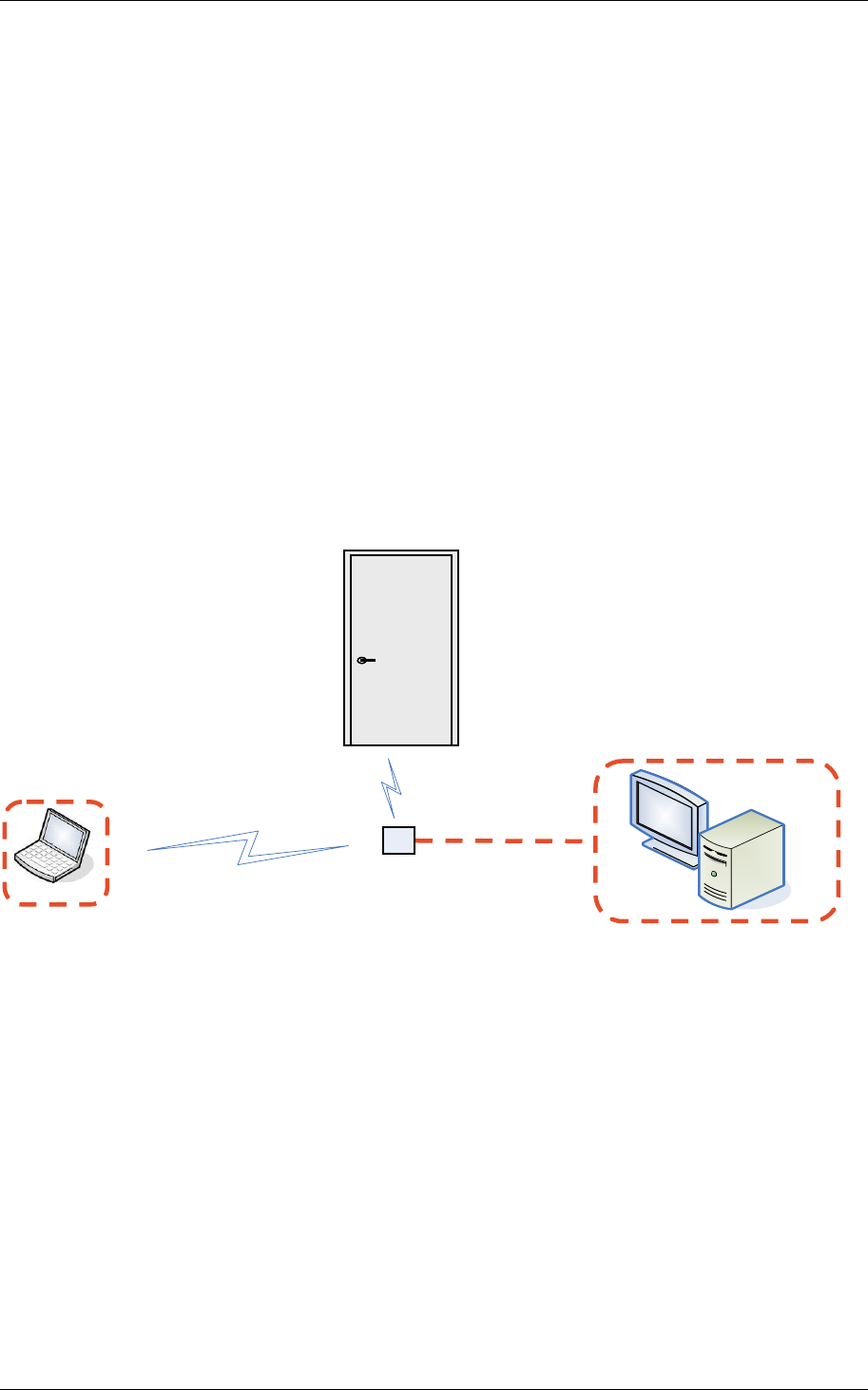
1.1 System description
The Aperio system
The Aperio system is used in the following way: The user holds a Mifare card to
the lock. The lock sends Mifare card credentials wirelessly to the Communication
Hub and the Communication Hub (wired through RS-485 or Wiegand) then
communicates with an EAC (Electronic Access Control) system. The EAC system
then makes the access decision. The decision is sent via the Communication Hub
to the lock and access is granted or denied.
The Aperio programming application
The programming application is used for the configuration of a door installation.
It is installed on a laptop. The laptop has an Aperio USB radio device connected
to one of its USB ports. The USB radio device enables the application to connect
to a Communication Hub and via the Communication Hub to the door lock. The
lock communicates via the Communication Hub either with the EAC or with the
programming application.
Figure 1, Aperio technology overview
Programming
application EAC system
Communication
Hub
RS-485/Wiegand
IEEE802.15.4 (2.4GHz)
Lock

Reference Manual
Aperio Technology
8 (91)
1.2 System components
The main components of the Aperio system are:
• Lock:
o IEEE 802.15.4 UHF interface.
o Mifare or iCLASS technology. (Depending on Lock type)
o AES 128 bit encryption.
o Battery pack (product dependent).
• Communication Hub:
o IEEE 802.15.4 UHF interface.
o AES 128 bit encryption.
o RS-485 interface or Wiegand interface to EAC system.
o 8-24V DC.
• Mifare card:
o Mifare classic, 13.56 MHz
o 1K or 4K memory.
o ISO 14443 standard, type A.
• iCLASS card
• USB radio device:
o IEEE 802.15.4 UHF interface.
o Aperio, USB Plug and play.
• Programming application:
o Software running under 32-bit versions of Windows XP, Vista or
Windows 7.
o Multi-language installation management tool.
o Encrypted installation database.

Reference Manual
Aperio Technology
9 (91)
2. Install the Communication Hub
2.1 EAC interface variants
The Communication Hub hardware offers two physical interfaces towards the EAC
system:
• RS-485
• Wiegand (available from HW version 1.5 and higher)
The firmware variant loaded into the Communication Hub controls what interface
to use.
Installation procedure and Communication Hub placement that are common to
the interface variants are here described first. Differences between the interface
variants are described in the end of this chapter.
2.2 Installation procedure
Follow these steps to install the Communication Hub:
1. Place the Communication Hub within 5 meters of the lock to which it will
be paired. See section 2.3 Placement of the Communication Hub.
2. Connect the Communication Hub according to the steps below:
a. Set configuration options on the DIP switch. Note! The EAC address
at use of an RS-485 interface to the EAC system can also be set
using the programming application.
b. Connect to the EAC system. Via RS-485 bus or via Wiegand signals.
c. Connect to the supply voltage. Connect the wires to 8-24V (positive
voltage) and GND (ground). Note! The Communication Hub must
be powered with a voltage between 8V DC and 24V DC. Minimum
current for robust operation is 120mA@8V, 110mA@9V,
80mA@12V, 40mA@24V.
3. If all communication is working, the LED now has a steady green light.
See more detailed information in the sections below.
Reference Manual
Aperio Technology
10 (91)
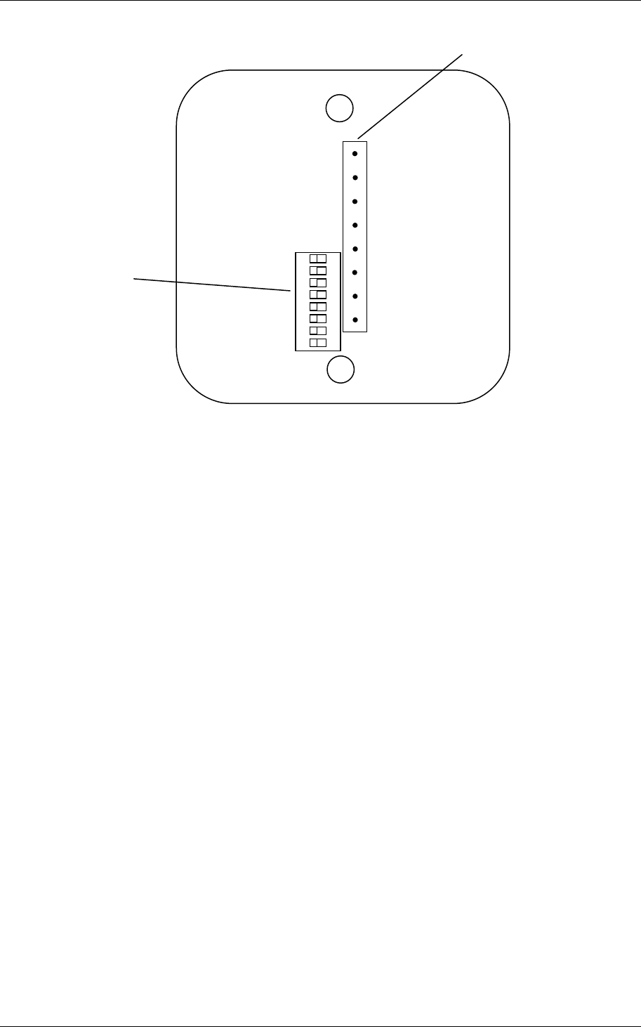
Figure 2, DIP switch and connectors
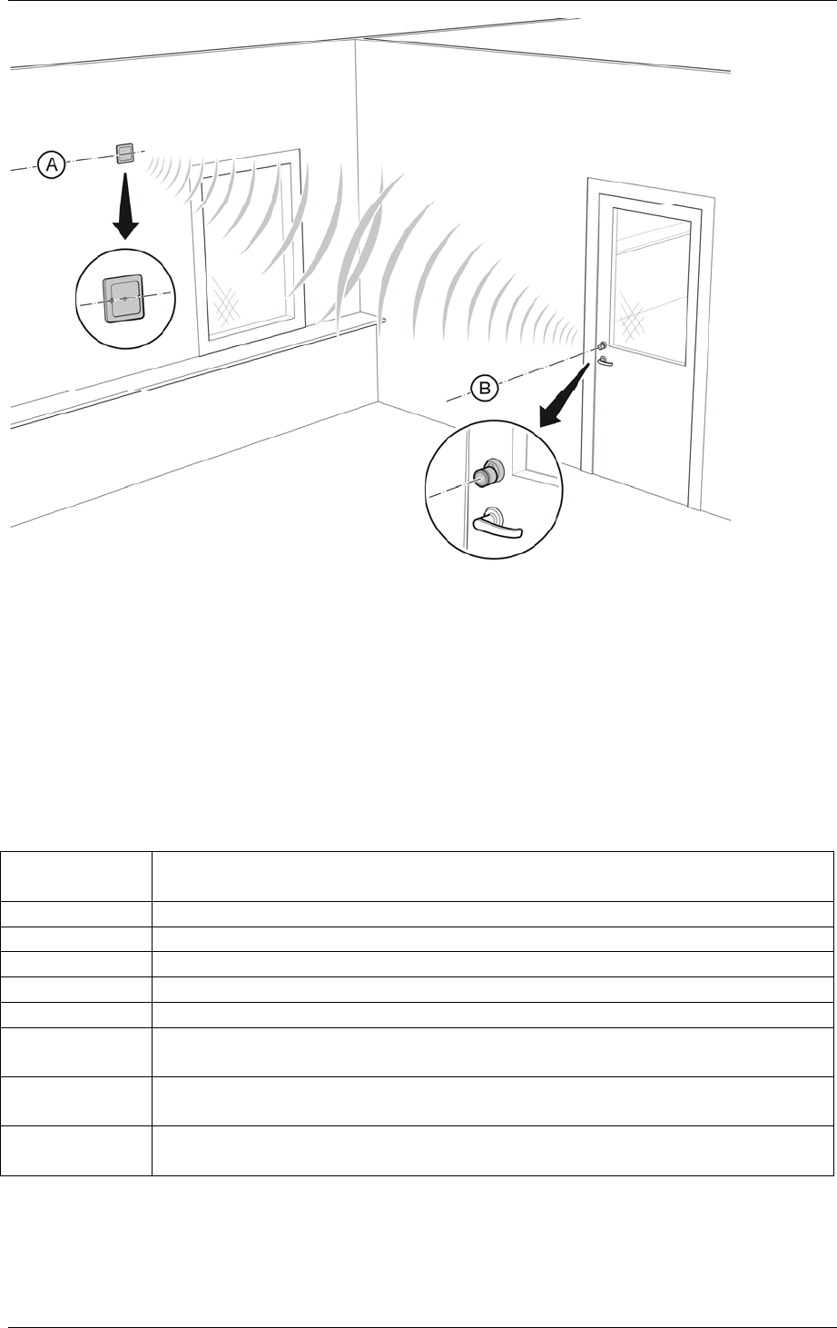
2.3 Placement of the Communication Hub
The link quality is acceptable for almost all positions and orientations of the
Communication Hub if it is placed within 2 meters of the lock. It is also
acceptable for most Communication Hub positions 2–5 meters from the lock and
in this case the recommended placement of the Communication Hub is
• within clear view of the lock
• oriented so that a line between its screw holes (A in the figure below) is in
parallel with an axis through the lock (B in the figure below)
• out of reach of any person.
1 2 3 4 5 6 7 8
Connectors
ON
8-24V
GND
RS485 B
RS485 A
DIP switch
GREEN
RED
DATA0
DATA1
Reference Manual
Aperio Technology
11 (91)
Figure 3, Recommended placement of the Communication Hub
2.4 RS-485 interface to EAC system
This subchapter describes the Communication Hub DIP switch and how to
connect the Communication Hub to the EAC system at use of an RS-485
interface.
2.4.1 RS-485 DIP switch description
The meaning of each individual DIP switch is summarized in the table below.
DIP Switch
number Description
1 RS-485 address, bit 0. ON = address bit set.
2 RS-485 address, bit 1. ON = address bit set.
3 RS-485 address, bit 2. ON = address bit set.
4 RS-485 address, bit 3. ON = address bit set.
5 RS-485 address, bit 4. ON = address bit set.
6 Controls use of an RS485 B pull down-resistor.
ON = 620 Ohm pull down connected.
7 Controls use of an RS485 A pull up-resistor.
ON = 620 Ohm pull up connected.
8 Controls use of a termination resistor between RS485 A and
RS485 B. ON = 100 Ohm termination connected.
2.4.2 Two ways of selecting the EAC address
The EAC address of the Communication Hub can be set in either of two ways:

Reference Manual
Aperio Technology
12 (91)
• By configuration from the programming application.
• By use of the DIP switch.
By selecting “RS-485 address from DIP switch” in the programming application,
use of the DIP switch address selection is enabled. This is also factory default in
the Communication Hub. If any other address is configured from the
programming application the DIP switch RS-485 address setting is irrelevant.
The switches allow selection of RS-485 address 0 to 31, where address 1 to 31 is
free for use in the Communication Hub. Selection of address 0 means that the
EAC interface of the Communication Hub is disabled. The address bits of the DIP
switch are read once at start of the program in the Communication Hub. This
means that the Communication Hub must be restarted for changes in address
from DIP switch to take effect. Note! If more than one Communication Hub is
connected to the same RS-485 bus, each Communication Hub must have a
unique RS-485 address.
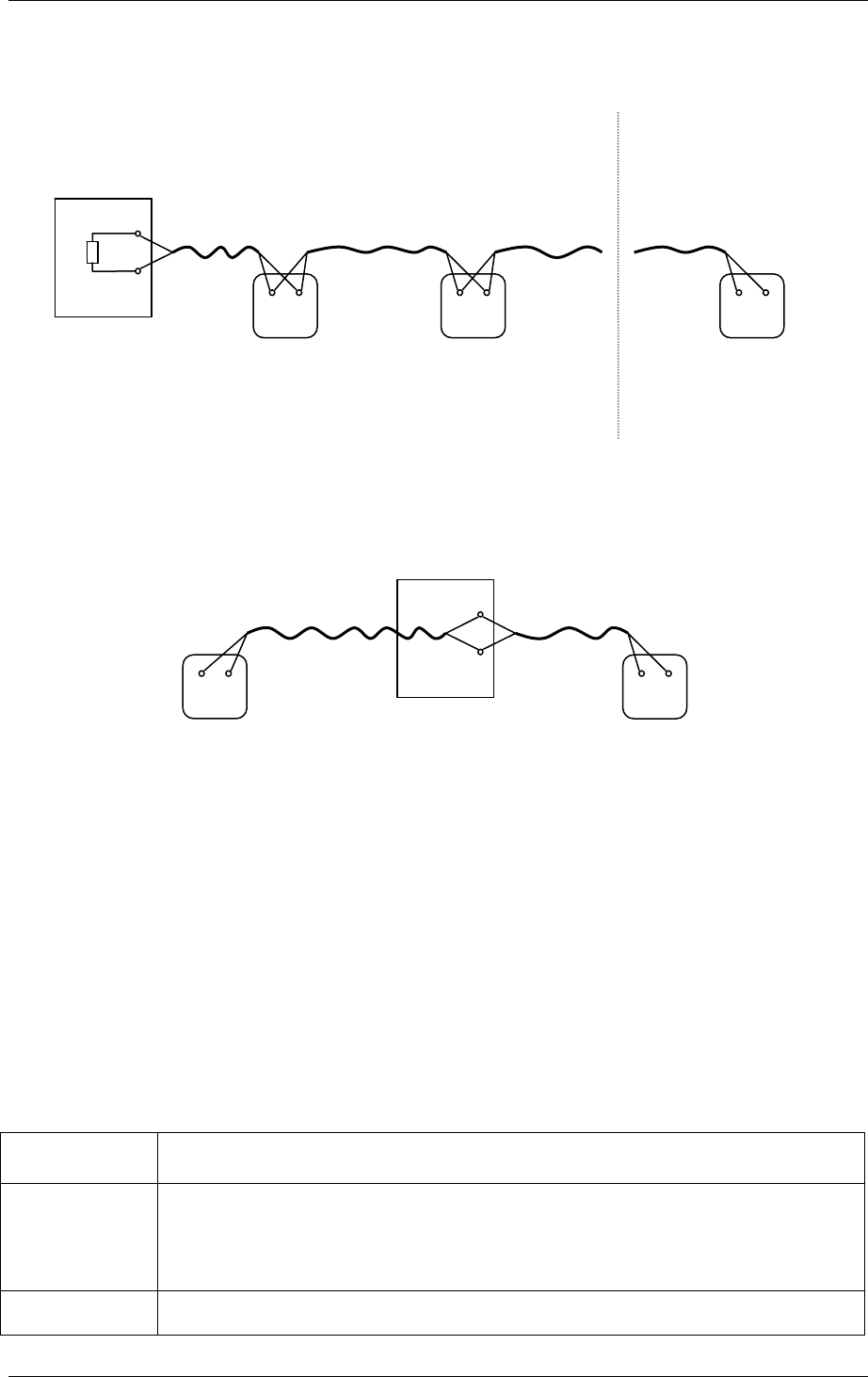
2.4.3 Connection of the RS-485 bus
The RS-485 bus should be made up of a twisted-pair cable with characteristic
impedance between 90 Ohm and 120 Ohm. Maximum bus length is about
1000m. Depending on the EAC system, a maximum of 32 units (EAC system
included) can be connected to the same bus.
If there is more than one Communication Hub to connect they should be
connected in a daisy chain (not as a star – see the first example below) on the
RS-485 bus so that all RS485 A connectors are connected together and all RS485
B connectors are connected together. Both ends of the RS-485 bus must be
terminated. A Communication Hub at the end of the bus must have switch 8 of
the DIP switch in position ON. All other Communication Hubs must have switch 8
of the DIP switch in position OFF. See the EAC documentation for proper
termination of the bus on the EAC side.
Pull up and pull down-resistors should be enabled once per bus. This means that
one Communication Hub on the bus should have switches 6 and 7 of the DIP
switch in position ON, if pull up and pull down from the EAC system is not used.
See the EAC documentation for use of pull up or pull down on the EAC side.
Reference Manual
Aperio Technology
13 (91)
Two examples of connection of multiple Communication Hubs to a single RS-485
bus of an EAC system:
Figure 4, Examples of Communication Hub connection
2.5 Wiegand interface to EAC system
This subchapter describes the Communication Hub DIP switch and how to
connect the Communication Hub to the EAC system at use of a Wiegand
interface.
2.5.1 Wiegand DIP switch description
How the Wiegand interface signals are used in detail is controlled by DIP
switches on the Communication Hub. See table below.
DIP Switch
number Description
1 Controls use of input signal LED Red to deduce an access
decision.
OFF => LED Red is ignored.
ON => LED Red is used.
See also flow diagrams in chapter nedan.
2 Controls timing of Data 0 and Data 1 out signals.
OFF => Pulse width 80us, pulse interval 2000us.
EAC System
A
B
A
Hub 2
DIP 6 OFF
DIP 7 OFF
DIP 8 ON
B
Termination
disabled
A
Hub 1
DIP 6 ON
DIP 7 ON
DIP 8 ON
B
EAC System
A
B
A
Hub 1 Hub 2 Hub X
end of bus
DIP 6 OFF
DIP 7 OFF
DIP 8 OFF
DIP 6 OFF
DIP 7 OFF
DIP 8 OFF
DIP 6 ON
DIP 7 ON
DIP 8 ON
A
A B B
B
Termination
enabled
Reference Manual
Aperio Technology
14 (91)
ON => Pulse width 40us, pulse interval 1000us.
3 Controls addition of parity bits on transmitted credentials.
One even parity bit before and one odd parity bit after the
actual credentials.
OFF => Addition of parity is disabled. Credentials are
transmitted as received.
ON => Addition of parity bits is enabled.
Note Transmitted credentials may include parity also if
addition of parity is disabled in the Hub Wiegand EAC
interface component. This since parity bits, if used,
typically are included already on the card.
4 Controls byte order of transmitted credentials.
OFF => The byte order is left as is.
ON => The byte order is reversed compared to what is
received as input to the Hub Wiegand EAC interface
component.
Note 1 This setting is ignored if the credential length
does not make up complete bytes.
Note 2 The byte order received as input to the Hub Wiegand
EAC interface component in the case of a 32 bit MIFARE UID
credential is UID[3], UID[2], UID[1], UID[0]. This means
that the byte order is already reversed earlier in the chain
compared to the order specified in RFID interface standard
ISO 14443-3.
5 Reserved for future use. Set to OFF.
6 Not applicable for Wiegand. Set to OFF.
7 Not applicable for Wiegand. Set to OFF.
8 Not applicable for Wiegand. Set to OFF.
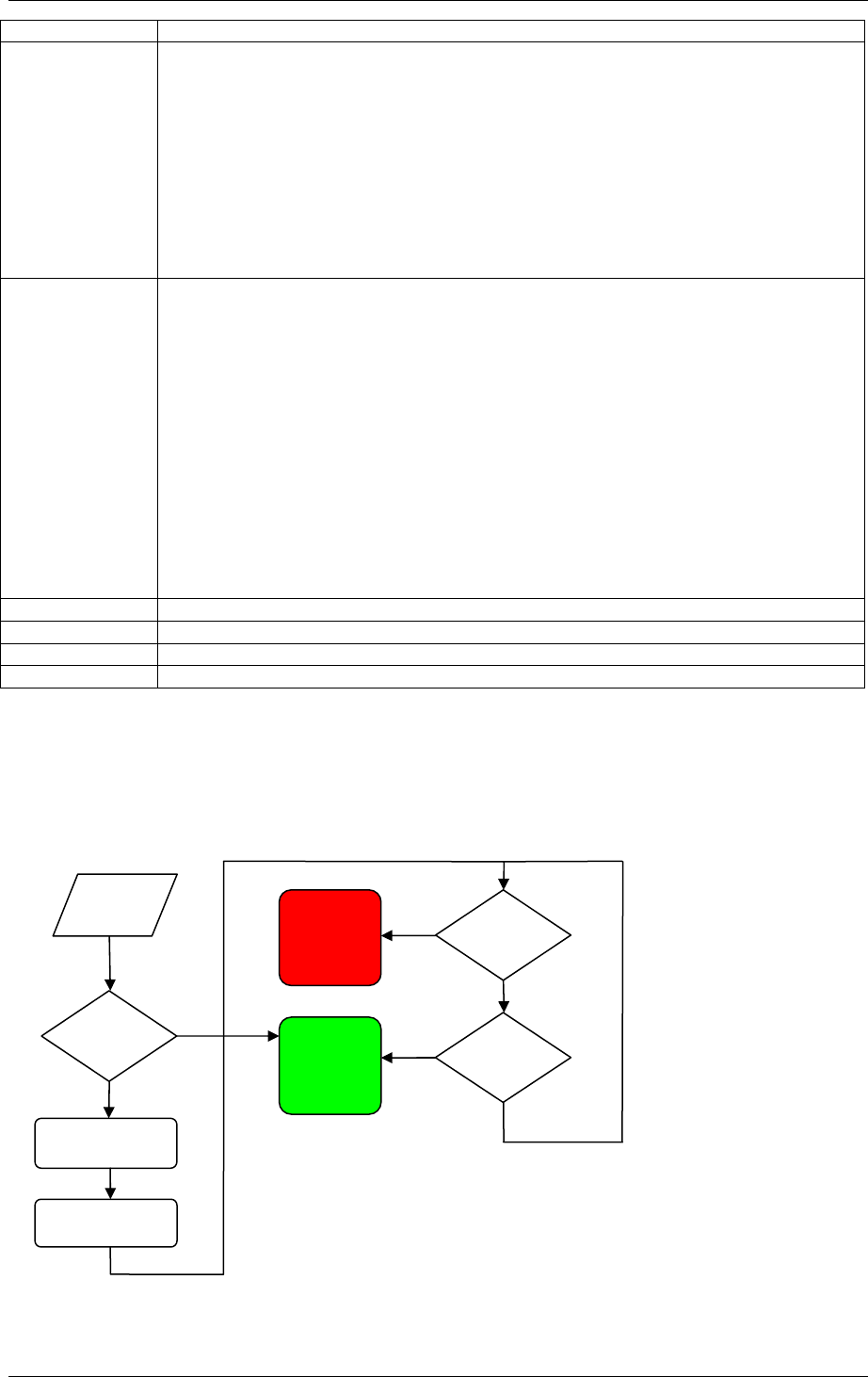
2.5.2 LED input signals and access decision
The flowcharts below show how the LED input signals are used to derive an
access decision. Two variants are depicted. Which variant that is used is selected
by DIP switch 1.
Figure 5, Access decision logic with single LED signal
Data
from
RFID
Green
LED
Active?
Transmit via
Wiegand if
On completion
start timer
(
1.5s
)
Signal
Access
Denied
to lock
Signal
Access
Granted
to lock
Timer
Expired?
Green
LED
Active? Yes
Yes
Yes
No No
No
Reference Manual
Aperio Technology
15 (91)
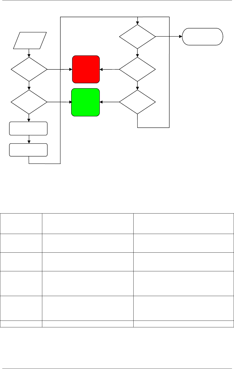
Figure 6, Access decision logic with two LED signals
2.5.3 Connection of Wiegand signals
Communication Hub hardware version 1.5 has four Wiegand signals plus ground. Purpose
and connection of these signals are described in the table below.
Hub
connector
designation
Description Connection
DATA0 Wiegand Data 0 signal. Output
from Communication Hub. Used
to transmit credentials.
Connect to Wiegand Data 0 on EAC
system.
DATA1 Wiegand Data 1 signal. Output
from Communication Hub. Used
to transmit credentials.
Connect to Wiegand Data 1 on EAC
system.
GREEN Wiegand LED Green signal. Input
to Communication Hub. Used to
deduce an access decision.
Connect to Wiegand LED Green
output on EAC system. Alternatively,
connect to a lock control relay output
on EAC system.
RED Wiegand LED Red signal. Input to
Communication Hub. Used to
deduce an access decision.
Connect to Wiegand LED Red output
on EAC system. Alternatively, leave
unconnected if signal is selected not
to be used by DIP switch 1.
GND Ground Connect to EAC system ground.
No
Yes
Data
from
RFID
Red LED
Active?
Green
LED
Active?
Transmit via
Wiegand if
On completion
start timer
(
1.5s
)
Signal
Access
Denied
to lock
Signal
Access
Granted
to lock
Timer
Expired?
Exit without
access decision
to lock*
Red LED
Active?
Green
LED
Active?
Yes
Yes
Yes
Yes
No No
No
No
*This means that
override credentials
will be used in the
lock.
Reference Manual
Aperio Technology
16 (91)
2.5.4 Configuration considerations
All DIP switches in position OFF on the Communication Hub give a default
Wiegand configuration that will fit most EAC systems. But better performance
and more functionality can result from a customized configuration.
DIP 1
If a signal from the EAC system is available that actively asserts an “access
denied” decision:
• Connect the EAC signal that asserts “access denied” to Communication
Hub signal LED Red.
• Set DIP switch 1 to ON.
This will give:
• Shorter response time at a denied access.
• Possibility to use override credentials in the lock.
DIP2
If the EAC system works with short Wiegand data pulse width, then set DIP
switch 2 to ON. This will give shorter response times, most notably at use of long
credentials.
2.6 Communication Hub LED indication
The Communication Hub has a single LED. It supports an optical scheme with
red, green and yellow. The indication scheme is described by the two figures
below:
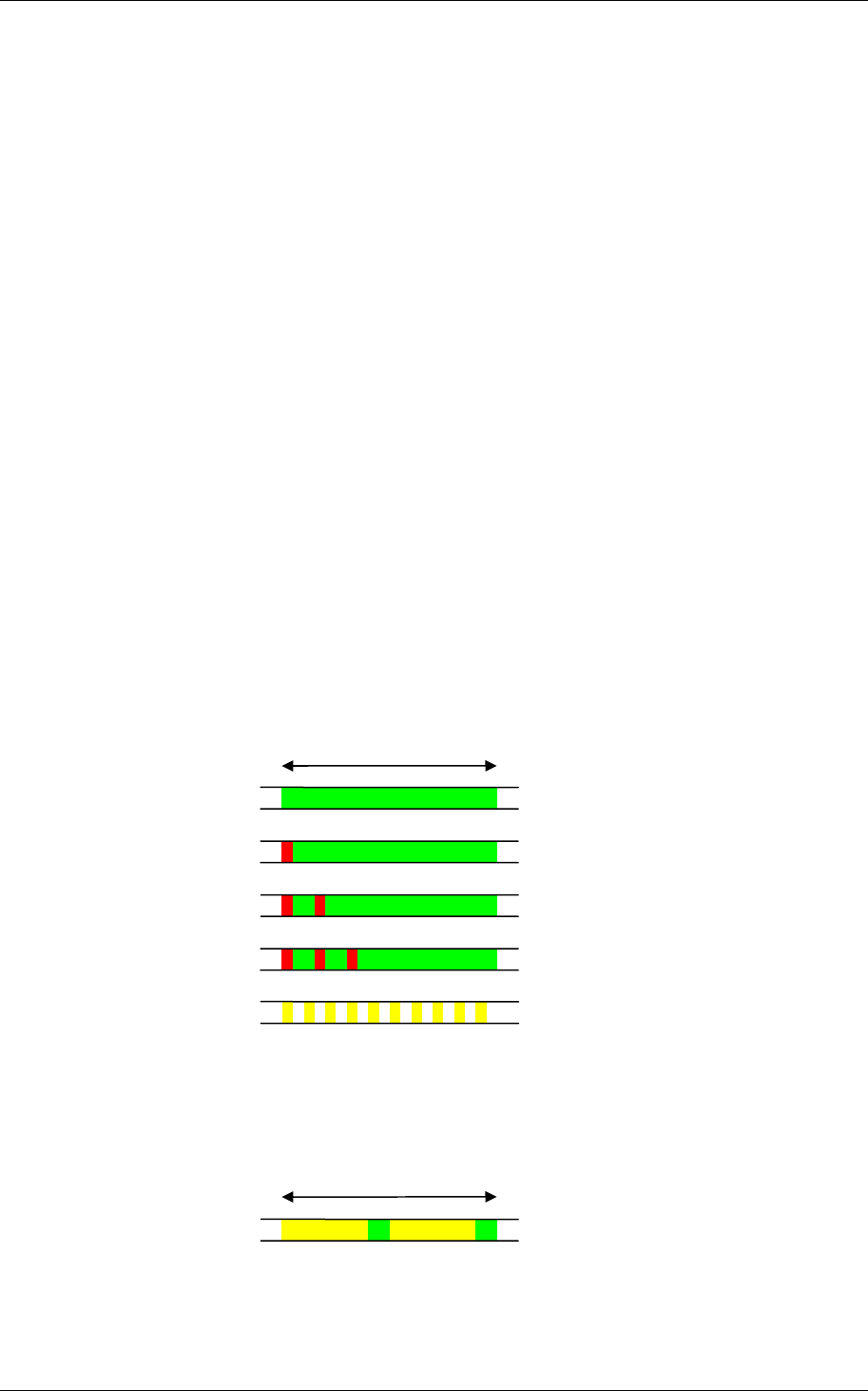
Figure 7, Communication Hub normal operation LED indication
Some special LED indication schemes are used during lock maintenance actions:
Figure 8, Communication Hub maintenance LED indication
2s
Pairing active Yellow + green
Online Green
2s
Aperio lock offline Green + one red flash
EAC offline Green + two red flashes
Aperio lock and EAC
offline Green + three red flashes
UHF communication Yellow + off, fast flash
Reference Manual
Aperio Technology
17 (91)
2.7 Lock normal operation LED indication
The lock has three LEDs. They support an optical scheme with red, yellow and
green. The indication scheme is described by the figures below:
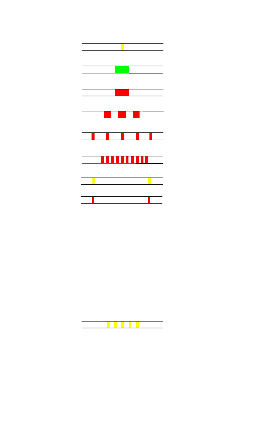
Figure 9, Lock normal operation LED indication
NOTE 1: When the lock mechanism is blocked (lock jammed) the knob must be
turned to release it.
NOTE 2: The “Error in lock” indication is also shown instead of the POST flashes
if the battery is not accepted as new after a power-on-reset.
2.8 Lock maintenance LED indication
Some special LED indication schemes are used during lock maintenance actions:
Figure 10, Lock maintenance LED indication
Enter configuration
mode Five yellow flashes
(.125 s each)
Access denied,
EAC offline Three red flashes (.5 s each)
Access granted,
EAC offline or online
One red flash (1 second)
One green flash (1 second)
Access denied,
EAC online
Lock mechanism is
blocked when closing1) Continuous red flashes
(.125 seconds every 1 second)
Card read
(configurable) One yellow flash (.25 second)
Error in lock,
maintenance required2) Ten red flashes (.125 s each),
repeated if lock can’t close
Battery reached end
of life, lock disabled Continuous red flashes
(.25 seconds every 5 seconds)
Time to replace the
battery Continuous yellow flashes
(.25 seconds every 5 seconds)

Reference Manual
Aperio Technology
18 (91)
2.9 Lock self test LED indication
After replacing the battery, a Power On Self Test (POST) is performed. The result
is indicated using a series of red and green LED flashes as is described by the
figure below:
Figure 11, Lock POST LED indication
The first flash is always red. If the POST fail, the color of the 16 trailing flashes
indicate the status of each individual test as described by the following table:
Blink Meaning if red Code in event log
2 Main board firmware corrupt 0x0001
3 Override list corrupt 0x0002
4 Production data corrupt 0x0004
5 Security data corrupt 0x0008
6 Configuration data corrupt 0x0010
7 Battery power low 0x0020
8 RFID reader circuit error 0x0040
9 Voltage regulator error 0x0080
10 Card detection circuit error 0x0100
11 Secure area communication error 0x0200
12 Secure area memory corrupt 0x0400
13 Secure area sensor or motor error 0x0800
14 Radio modem communication error 0x1000
15 Radio modem memory corrupt 0x2000
16 Radio modem configuration error 0x4000
17 Radio modem RF circuit error 0x8000
NOTE: If the battery is not accepted as new after a power on reset, no POST is
performed, instead the 10 quick red flashes used to indicate “Error in
lock” is shown.
1 2 3 ... 17
...
Failure during POST
One red flash followed by 16
red or green flashes (.5 s each)
POST successful One red, one green flash
(
1
second each
)
Reference Manual
Aperio Technology
19 (91)
3. Install the programming application
3.1 Computer specifications
The Aperio Programming Application should be installed on a computer with the
following specifications:
• Laptop
• 32-bit version of Windows XP, Vista or Windows 7
• USB 2.0
3.2 Files needed for the installation
To be able to install the programming application, the following files are also
needed:
• License file
• Encryption key file
These files should be delivered together with the Aperio software from your lock
distributor. To be able to install the programming application the Aperio software
must be available or saved in the appropriate folders on your laptop.
3.5 Install the programming application
Follow these steps to install the programming application:
1. Unpack the Aperio distribution file (ex. progapp-x.y.z.zip), including the
setup.exe file, in a temporary folder.
2. Run the setup.exe file. Result: The Aperio programming application is
installed.
3. Click Start–All Programs–Aperio Programming Application–Start.
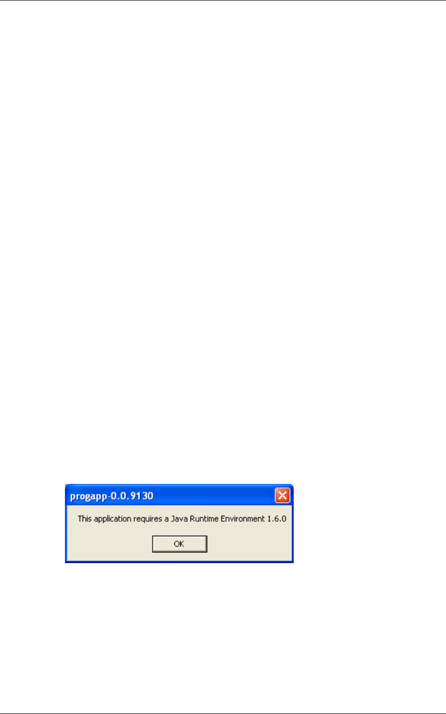
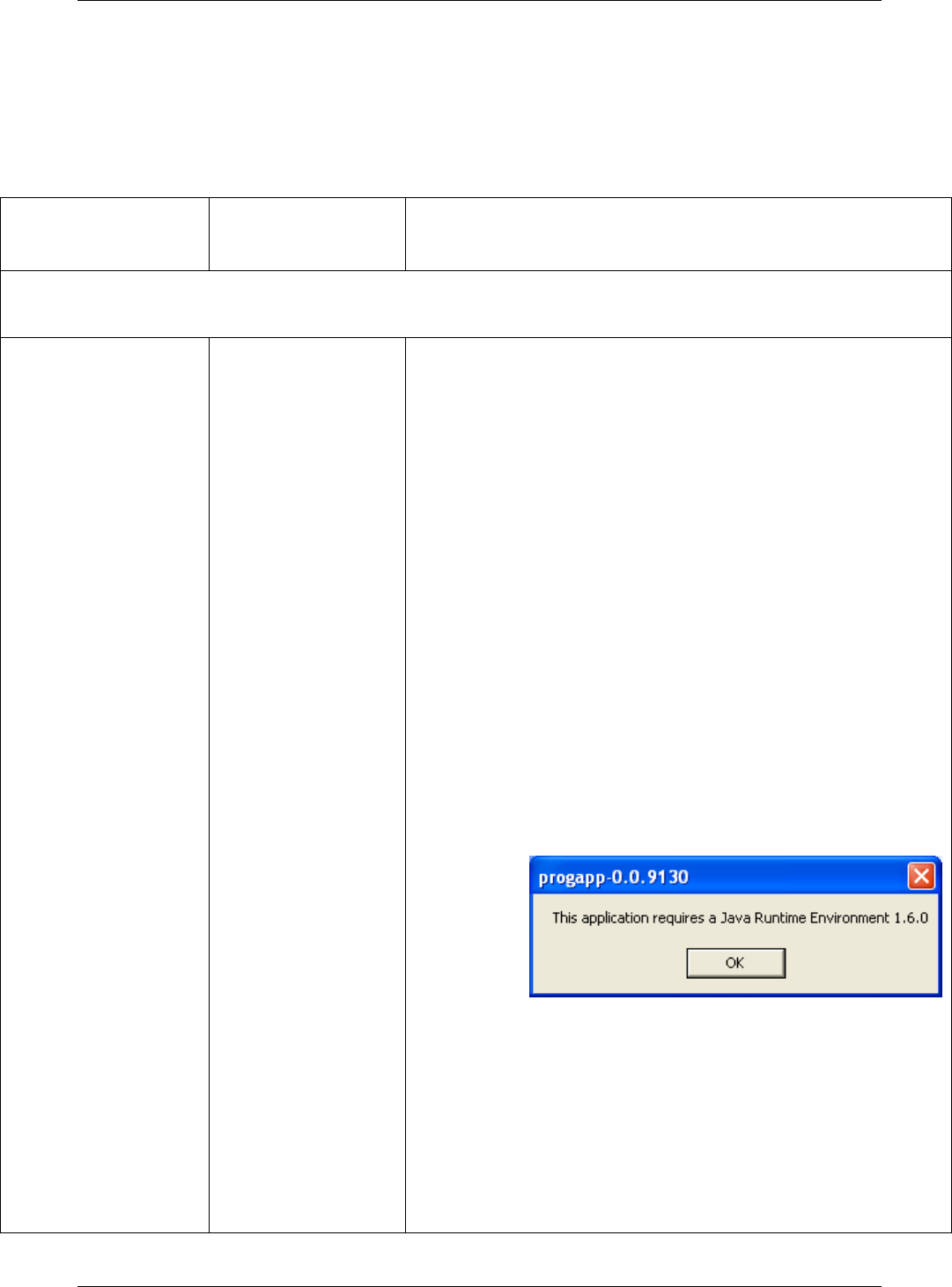
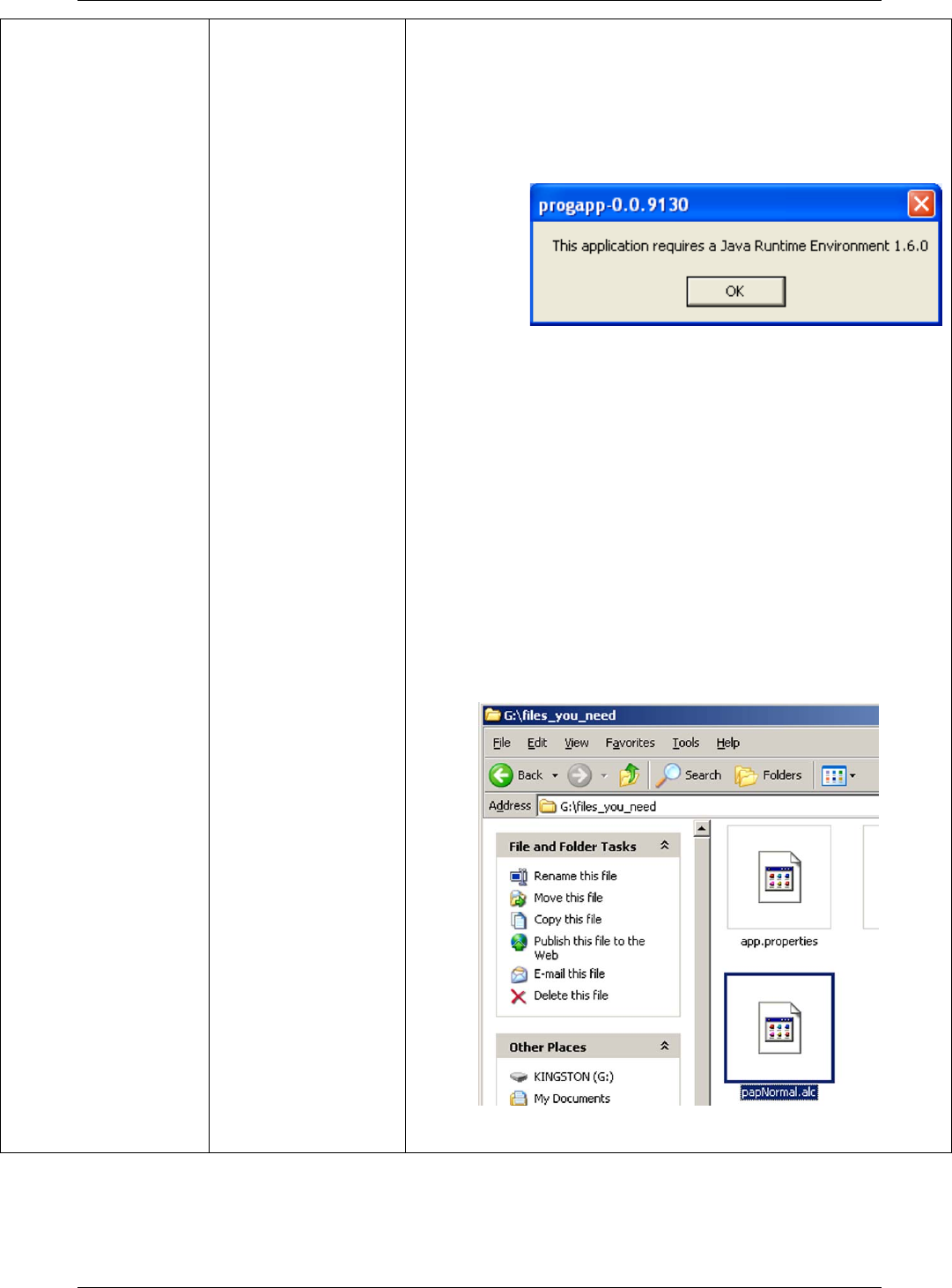
4. At startup the Aperio Programming Application checks that the correct java
version is installed. If the correct version is not installed the following will
occur:
a) A warning will be shown. Click OK to close the window.
b) You are redirected to a page from where you can download the
required Java version. Install the required version and restart the
Aperio Programming Application according to Fel! Hittar inte
referenskälla. above.
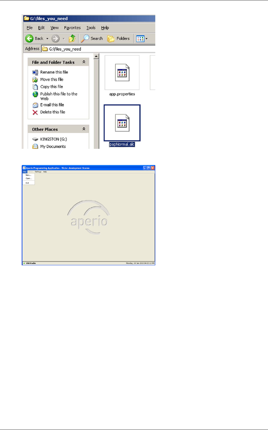
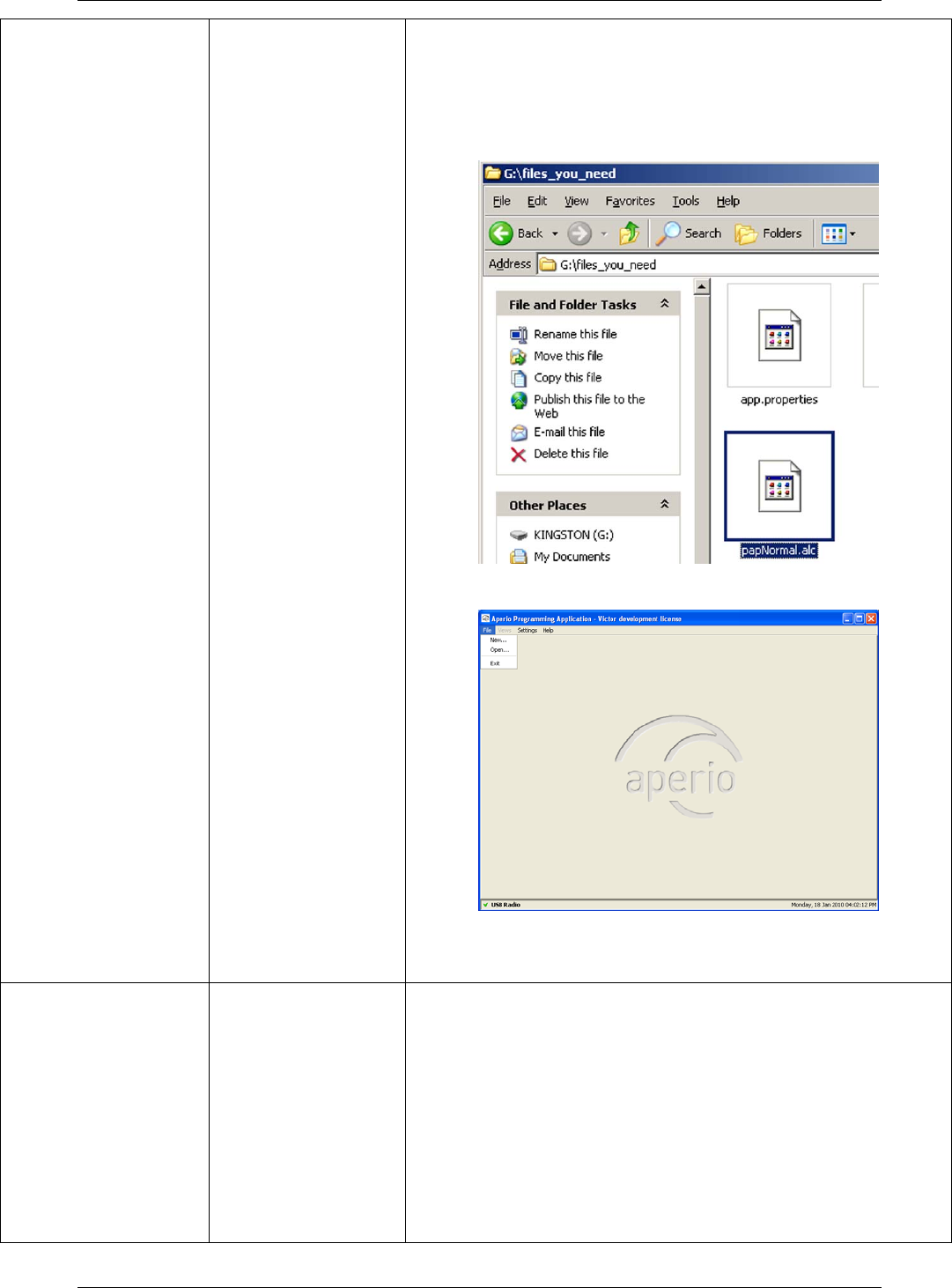
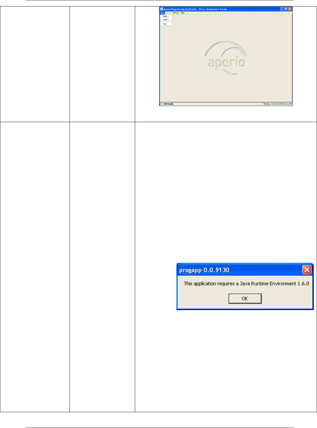
5. Browse for the license file (.alc), select it and click OK. Result: The Aperio
Programming Application starts. Note! The license file should be delivered
in a separate e-mail or on a USB memory stick.
6. If this is the first time you install the Aperio Programming Application, you
need to follow the steps in chapter 3.6 Install the USB radio driver before
you can start the program.
Reference Manual
Aperio Technology
20 (91)
3.6 Install the USB radio driver
3.6.1 New Installation of Aperio Programming Application
Follow these steps to install the USB radio driver:
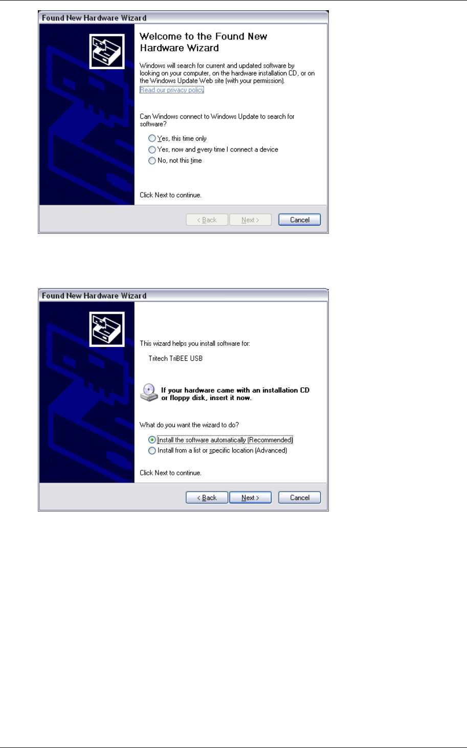
1. Connect the Aperio USB radio device to a USB port on your laptop.
Result: The Found New Hardware Wizard is opened.
Reference Manual
Aperio Technology
21 (91)
2. Select No, not this time (do not use Windows Update to search for
software) and click Next.
3. Select Install from a list or specific location (Advanced) and click Next.
Reference Manual
Aperio Technology
22 (91)
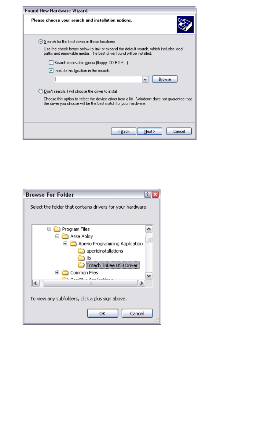
4. Select Search for the best driver in these locations. Unselect Search
removable media, select Include this location in the search and click
Browse.
5. Select the Tritech TriBee USB Driver folder located in the Aperio
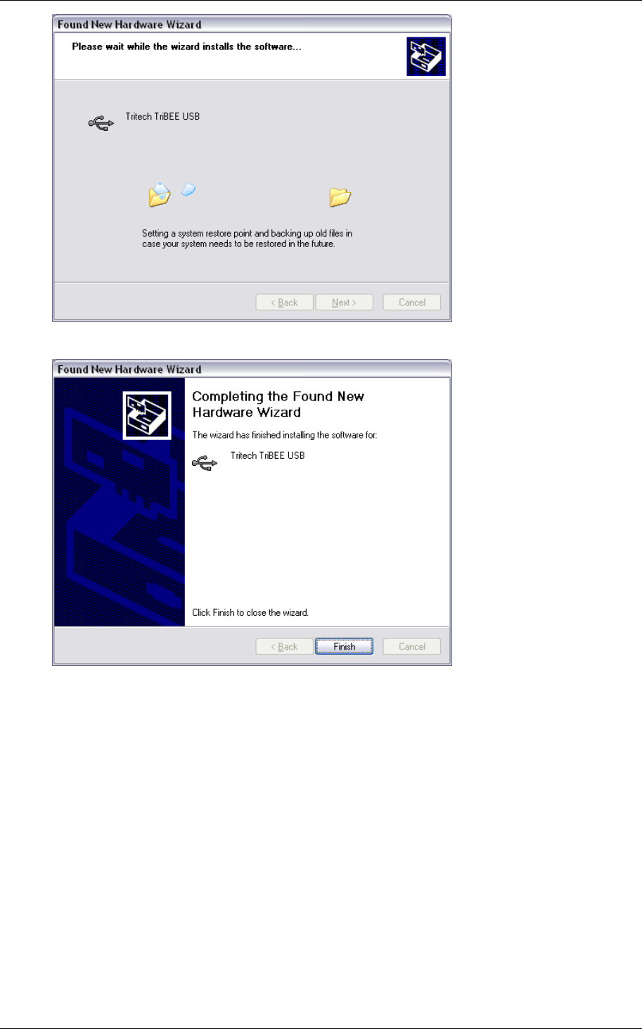
Programming Application main folder. Click OK and then Next (in the
Found New Hardware Wizard). Result: A confirmation dialog shows that
the driver is being installed.
Reference Manual
Aperio Technology
23 (91)
6. Click Finish. Result: The system will now find a new hardware, TriBee USB
Serial Port.
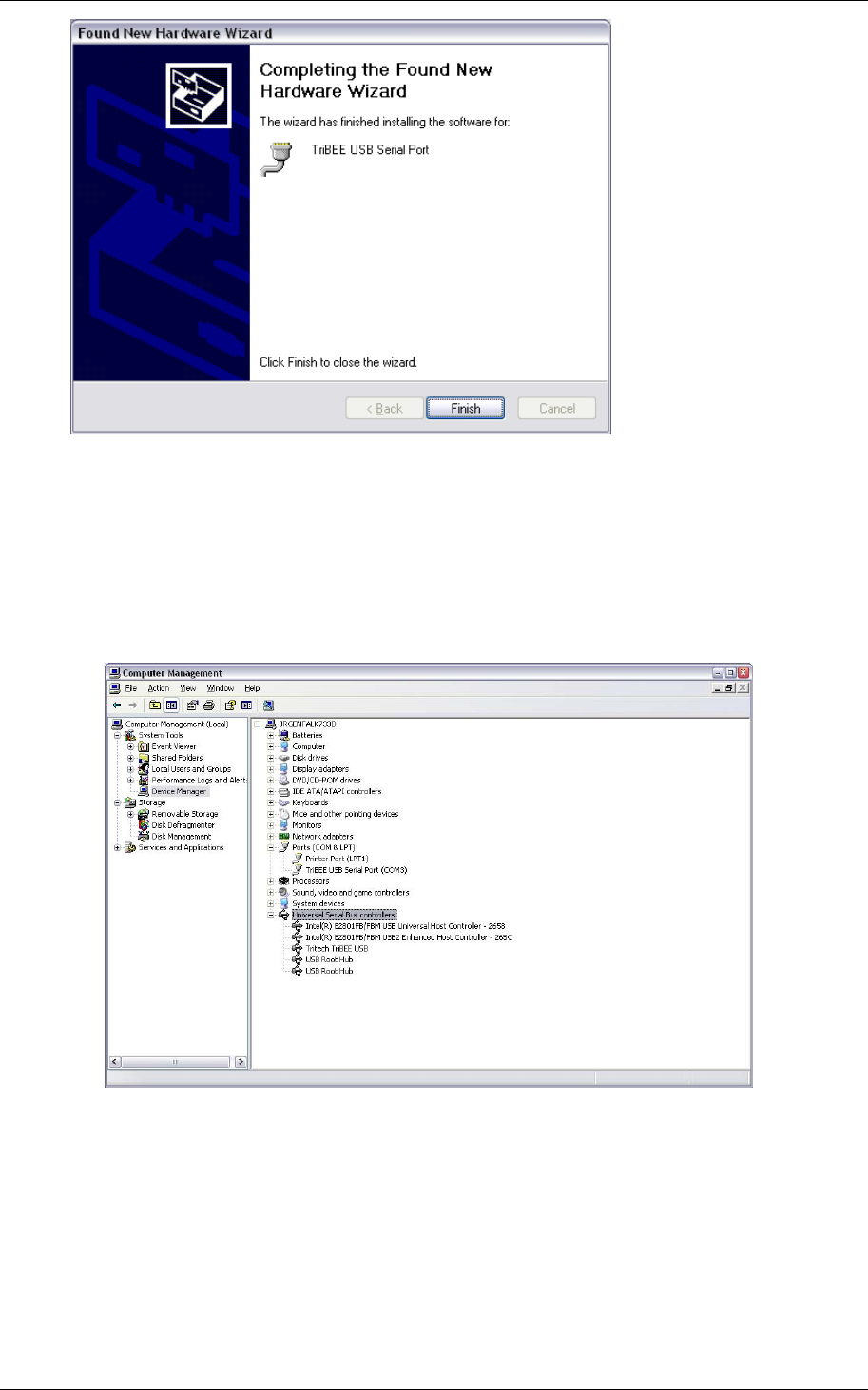
7. Repeat steps 2–6 of the procedure above for the serial port driver. When
done, click Finish. Result: Windows has installed the drivers and the
hardware is ready to use. Windows shows a pop-up message indicating if
the driver installation was successful.
Reference Manual
Aperio Technology
24 (91)
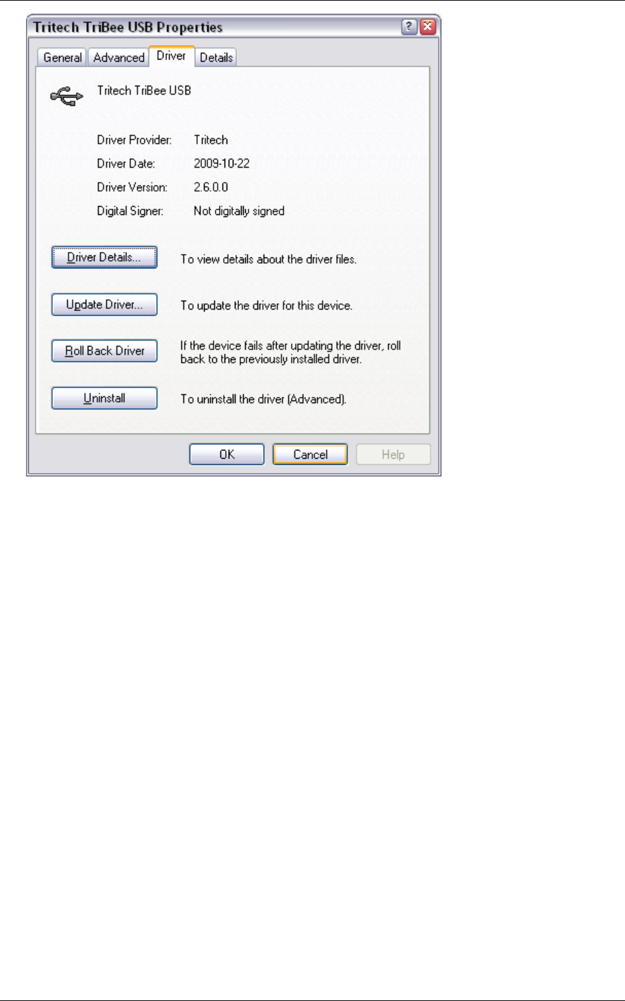
8. Verify that the drivers are working by opening the Computer Management
Control Panel:
a. Verify that there is a TriTech TriBee USB under the USB Controller
section and that there is a TriBee USB Serial Port under the Ports
(COM & LPT) section and that there are no warnings or error
indications.
3.6.2 Update the driver in an existing Aperio Programming Application
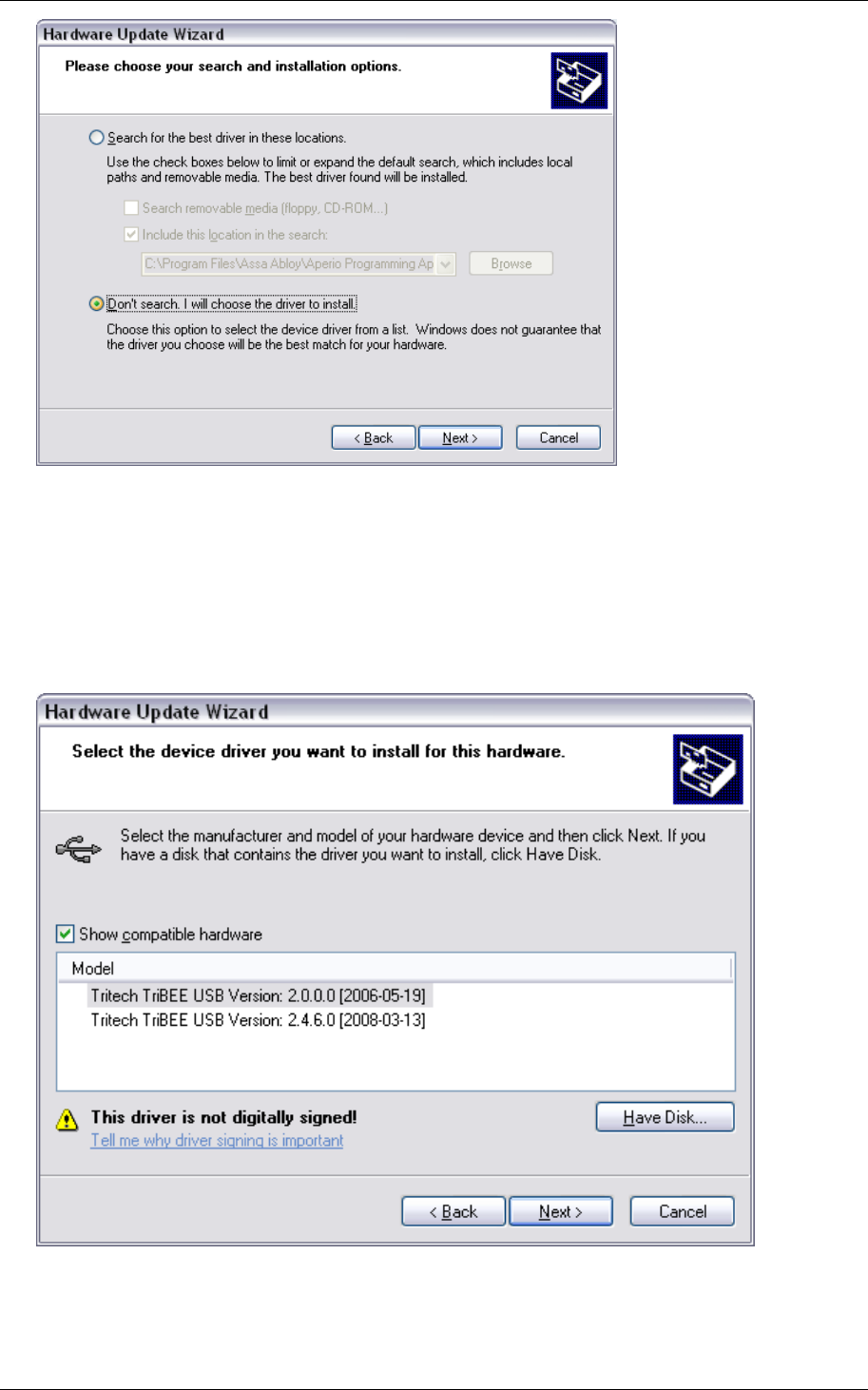
To update an existing Tritech TriBee USB Driver you need to manually add the
driver. First check your current version by opening the Computer
Management Control Panel. Double click on the Tritech TriBee USB Serial Bus
driver under Universal Serial Bus controllers and open the Driver tab. Latest
version is 2.6.0.
Reference Manual
Aperio Technology
25 (91)
If you have an older driver that works fine, you don’t need to upgrade, but if
you experience problems with the driver or if you are running the Aperio
Programming Application on Windows Vista, you are encouraged to ensure
that you are using the latest driver.
You need to update both the TriTech TriBee USB bus driver and the Tritech
TriBee USB port driver.
NOTE: Please follow the instruction below exactly step-by-step. It is very
important not to let Windows find the driver automatically, since it will always
fail and pick the wrong version.
1. Open the Windows Hardware Update Wizard for the Tritech TriBee USB bus
driver by clicking on the “Update Driver” button in the Tritech TriBee USB
properties window (see above).
Reference Manual
Aperio Technology
26 (91)
2. Make sure that the “Don’t search. I will choose the driver to install” option
is selected and then click “Next>”. Click on the “Have Disk…” button and
Windows will guide you in three steps to select the Tritech USB driver folder
located in the Aperio Programming Application program files folder. Note that
the content of this window can vary depending on what version of Aperio
Programming Application you have installed.
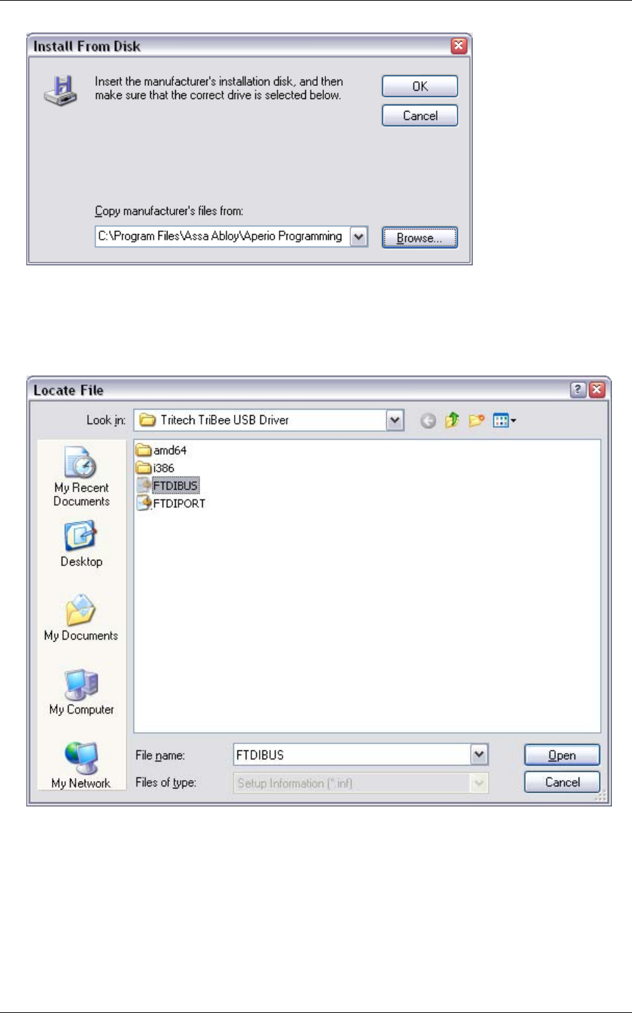
3. After clicking on “Have Disk…”, in the Install From Disk window, click on
“Browse…” and navigate to the Aperio Programming Application and select the
Tritech TriBee USB Driver folder.
Reference Manual
Aperio Technology
27 (91)
4. Select the FTDIBUS setup information file when upgrading the Tritech
TriBee USB bus driver and select the FTDIPORT when upgrading the Tritech
TriBee USB port driver. Please make sure that you select the correct inf-file
for the driver you are updating.
5. Click “Open” and wait for Windows to install the new driver. If not already
done, repeat step 1-5 for the Tritech TriBee USB port driver.
6. Reboot Windows and open the properties dialog in the Computer Management
Control panel again for the two TriTech TriBee USB drivers and verify that they
are using the latest driver version 2.6.0.
Reference Manual
Aperio Technology
28 (91)
4. Make a new door installation
Proper handling of encryption keys is essential to lock security!
It is absolutely necessary to use the customer encryption key to ensure a
secure and encrypted communication with the lock.
The Customer Key should be handled with the same care as the Master Key in a
traditional MKS. A person with access to the Customer Key can gain unauthorized
access to any Aperio door in the system. Once loaded into the Programming
Application, it will be stored encrypted in a local database and should be erased
from the hard drive. A copy should be stored safely.
4.1 Instruction
Follow these steps to make a new door installation:
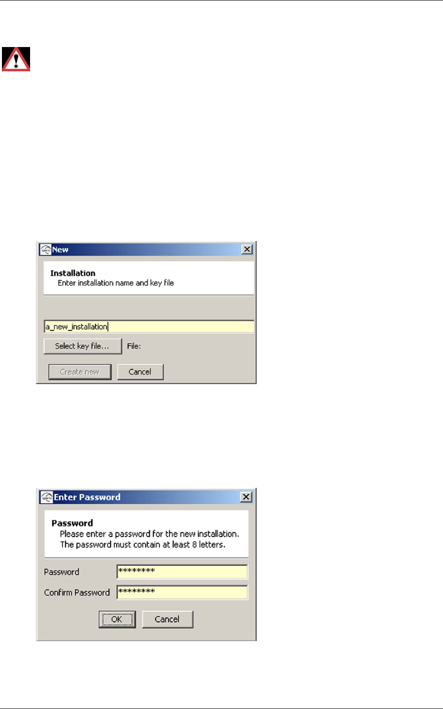
1. Select File–New in the Aperio Programming Application.
2. Enter a name for the installation and click Select key file.
3. Select the key file and click Select. Note! The xml-file (key file) containing
the encryption keys should be delivered via encrypted e-mail or on a USB
memory stick.
4. Click Create new.
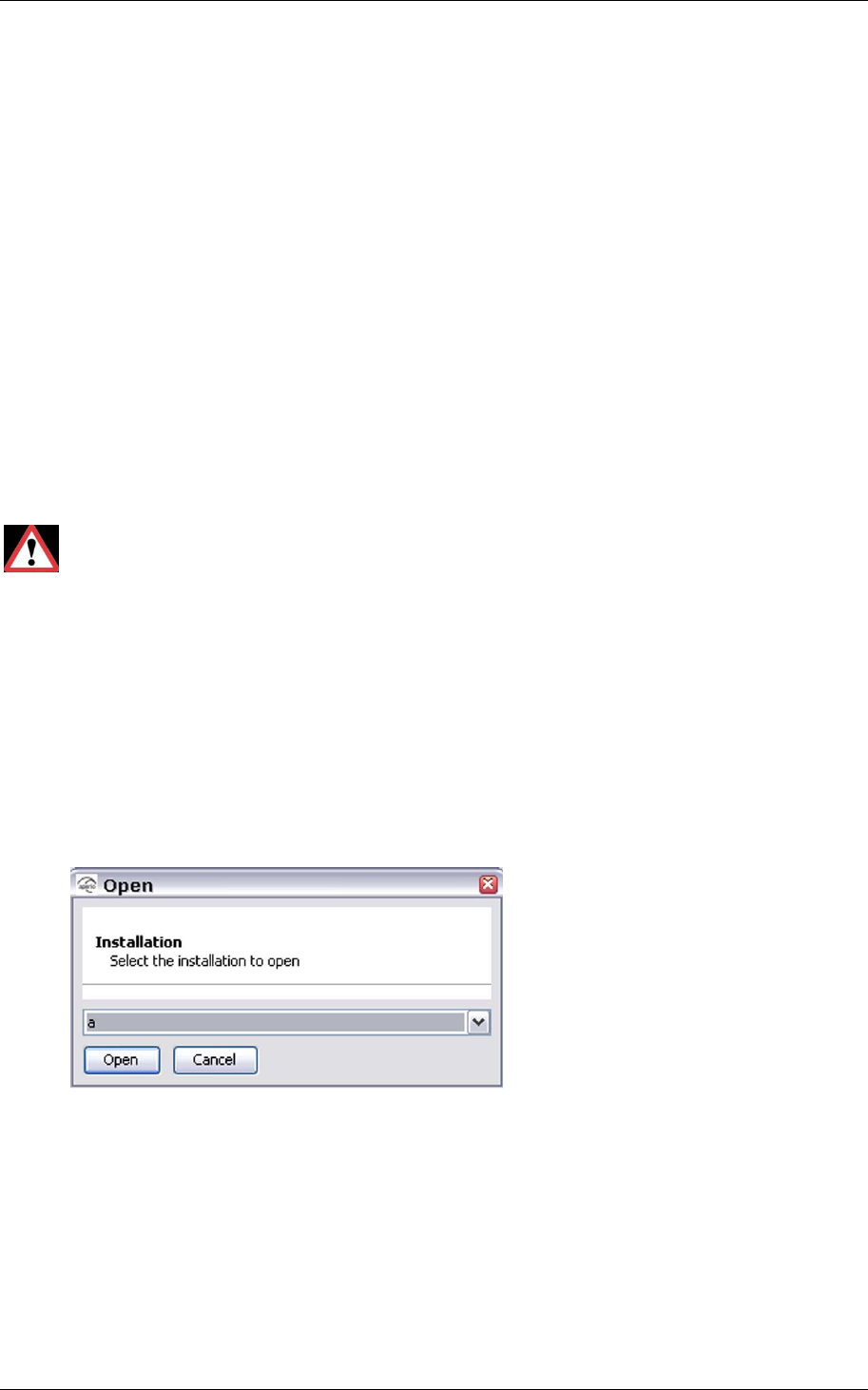
5. Enter a password of at least 8 characters for the door installation and
confirm it. Click OK.
Reference Manual
Aperio Technology
29 (91)
5. Make the first configuration of a door installation
5.1 Purpose of the first configuration
The purpose of the first configuration of a door installation is to
• ensure that the Aperio system is in normal operation mode.
• verify a stable and secure operation of the lock.
Making a first configuration of a door installation includes
• switching security mode
• integration with an EAC.
• setting of override credentials.
For some installations it could also include
• card reading configuration.
• configuration of status and alarm messages.
• configuration of the radio communication.
Proper handling of encryption keys is essential to lock security!
If the installation and first configuration is not performed properly the
radio communication will not be secure and the lock will therefore be vulnerable
to intrusion attempts.
5.2 Scan for Aperio locks
Follow these steps to scan for doors:
1. Open the Aperio Programming Application by clicking Start–All Programs–
Aperio Programming Application–Start.
2. Select File–Open, select the installation to scan and click Open.
3. Enter the password and click OK. Result: The Installation view is opened.
Reference Manual
Aperio Technology
30 (91)
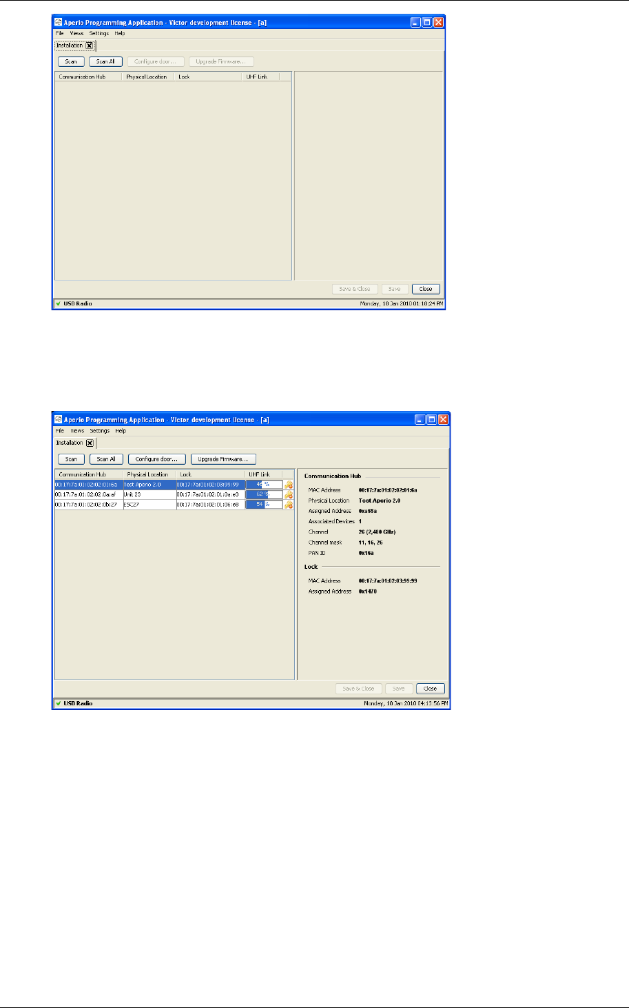
4. Click Scan. The Scanning progress bar is shown during the scan. Result:
All Communication Hubs within reach of the USB Radio device of your
computer are displayed in the scan result table.
5. Click Scan again if none or not all of the Communication Hubs are found.
Note! If scanning fails several times you may need to perform Scan all.
6. Select a door in the table if you want to view detailed information of its
Communication Hub and lock. The following information is shown:
• Communication Hub. The MAC address of the Communication Hub.
• Physical Location. The physical location specified by the user. This is a
description that may be 20 characters long.
• Lock. Indicates if there is a lock paired with the Communication Hub. If
there is a paired lock the MAC address of the lock is shown. If not, n/a
is shown.
Reference Manual
Aperio Technology
31 (91)
• UHF Link. Indicates the strength of the UHF wireless link (through the
USB Radio device) between the Communication Hub and the Aperio
Programming Application.
• Security Mode. Indicates the security mode of the Communication Hub.
Customer mode Door is using secure radio communication
with the customer encryption key.
Manufacturing
mode Door is using unsecure radio
communication with the default encryption
key.
7. Locate a door by checking the last three bytes of the Communication Hub
MAC address (ex. 02:01:3e) in the scan result table. The same characters
should be on a label on the cover of the Communication Hub.
5.3 Update the door configuration
Follow the steps below to update the door configuration. Note! The changes you
make during the update of the door configuration are not carried out until you
perform the device update.
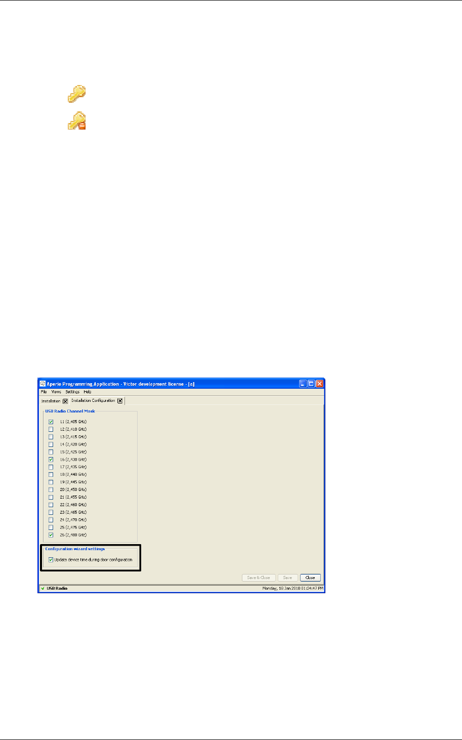
1. Open Views–Installation Configuration.
2. Check Update device time during door configuration and click Save &
Close.
3. Open Settings–User Settings.
4. Check Show advanced settings and click Save & Close.
5. Select a door in the scan result table and click Configure door.
Reference Manual
Aperio Technology
32 (91)
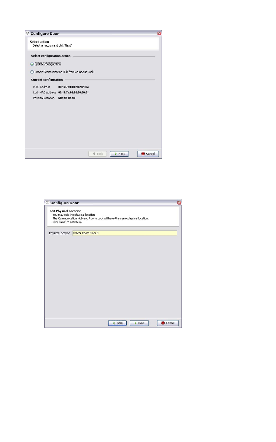
6. Select Update configuration in the Select configuration action field and
click Next.
7. Edit the Physical location of the door if necessary. Use a description that
clearly describes the physical location of the door. When you scan for
doors the physical location will be shown in the scan result table. Click
Next.
Reference Manual
Aperio Technology
33 (91)
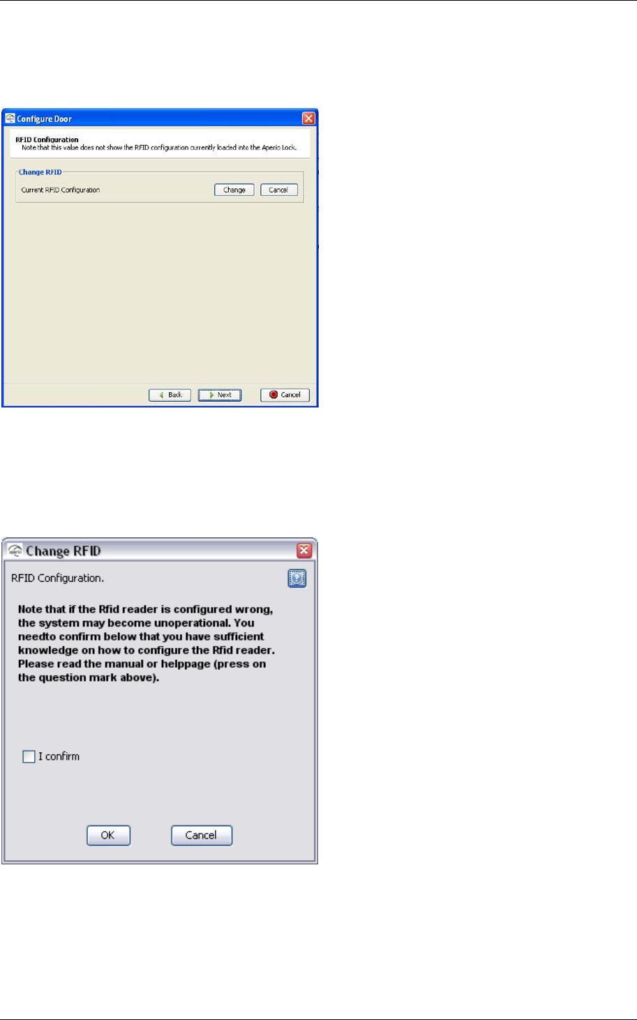
8. Click Change in the Mifare RFID Configuration dialog box if you need to
change the RFID configuration, or click Next.
9. Select I confirm to confirm that you have the proper knowledge of Mifare
configuration and that you are aware that a faulty configuration could lead
to non-functional locks. Click OK. Note! You have to confirm this every
time.
Reference Manual
Aperio Technology
34 (91)
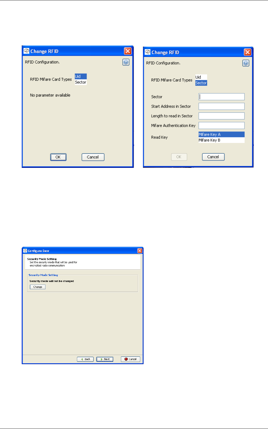
10.Select the Mifare card type. Currently UID and Sector reading is
supported. See an example of a sector reading layout in Appendix A,
Mifare RFID Configuration Online Help.
11. Set the parameters for the selected card type and click OK. If you select
UID configuration, no parameters need to be set. If you need help during
the RFID configuration, click the question mark in the upper right corner of
any of the dialog boxes to open the online help (or read Appendix A,
Mifare RFID Configuration Online Help).
Note! All parameters are mandatory and you can’t click OK until a valid
combination of parameters is entered.
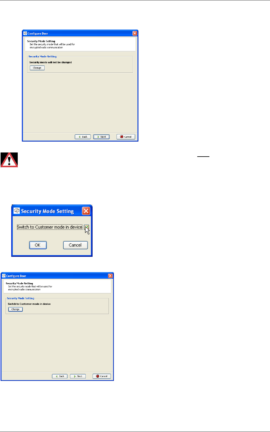
12.Click Change in the Security Mode Setting dialog box if you want to
change the security mode, or click Next.
When you want to change to Customer mode do as described in step 14-
15 below.
Reference Manual
Aperio Technology
35 (91)
Note: The Default mode is Manufacturing mode, you should always
change it to Customer mode.
If the door is set in Customer mode you should not change to
Manufacturing mode in this step in the wizard!
If you change to Manufacturing mode key the lock will no longer
be using secure radio communication.
13.Select Switch to Customer mode in device and click OK.
14.Click Next
Reference Manual
Aperio Technology
36 (91)
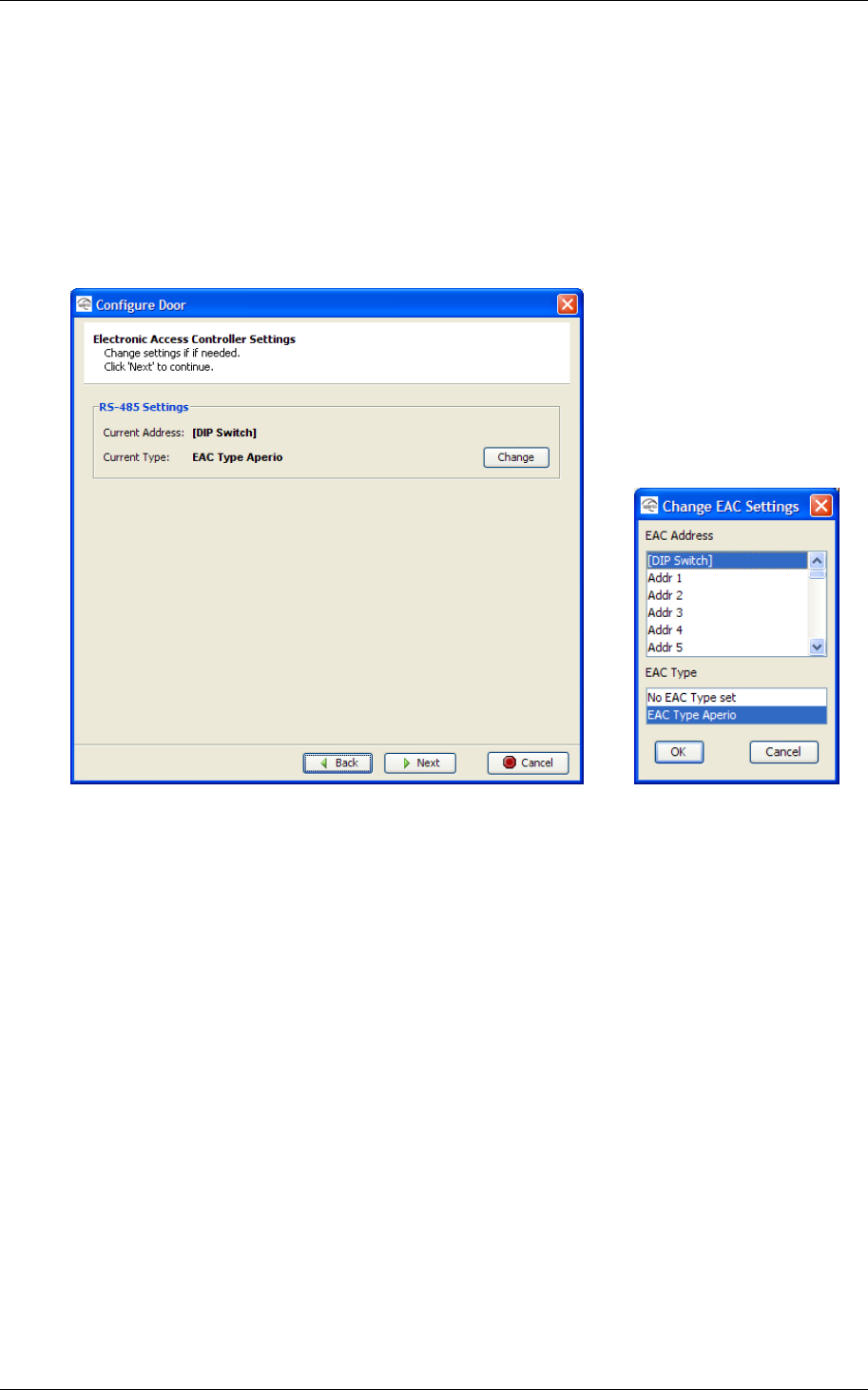
15. Click Change if you need to change the EAC address and/or type.
Note! You can also set the EAC address during the installation of the
Communication Hub using the DIP switch. See section 2.2 In, 2.4 RS-485
interface to EAC system
This subchapter describes the Communication Hub DIP switch and how to connect the
Communication Hub to the EAC system at use of an RS-485 interface.
16. and 2.4.2 Two ways of selecting the EAC address above.
17.Select address and/or type and click OK. Click Next.
Reference Manual
Aperio Technology
37 (91)
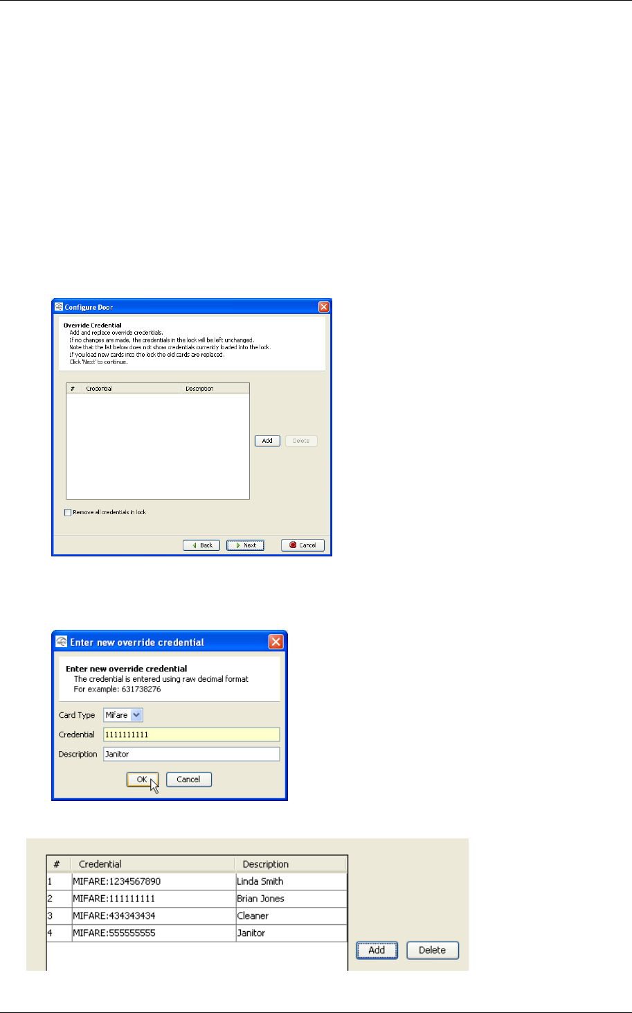
5.4 Set the override credentials
The override credentials are used to gain access to the area when the EAC is
offline. Only the credential cards from the override list will be granted access
when the system is offline. You may add 10 override credentials to a door.
Note that you do not have to enter the override credential data manually for
every door to be configured. An easy and efficient way of storing the same
override credentials in all the locks when configuring the door is to save the
override credential configuration to local storage. This is described in section 5.6
Save the configuration to local storage.
Follow these steps to set the override credentials:
1. Click Add to add a new override credential.
2. Select the Card Type, enter the UID (Unique Identification Number) for the
override card in the Credential field. You may also enter a description of
the credential. Click OK.
3. Enter all credentials to be sent to lock.
Reference Manual
Aperio Technology
38 (91)
4. Select an override credential and click Delete if you want to delete a
credential from the list.
5. Check Remove all credentials in Aperio Lock if you want to remove all the
credentials in the lock.
6. Click Next after setting the override credentials.
5.5 Set the advanced settings
NOTE: To see this panel, you must have the “Show advanced settings” check-
box checked on the “User Settings” page.
Follow these steps to set the advanced settings:
1. Click Change if you want to change the channel mask. See instruction in
section 8.2 Change the channel mask. Click Next.
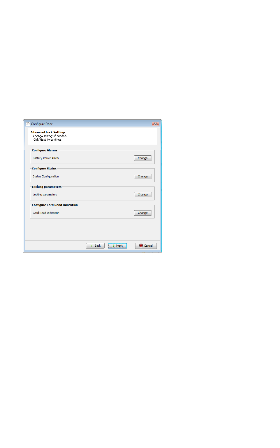
2. Click Change in the applicable field of the Advanced Lock Settings dialog
box if you want to change the
a. battery power alarm – configuration of the voltage level and with
what interval in minutes the battery in the lock should be checked.
b. status messages and report intervals – configuration of which
statuses the message should contain and with what interval the
message should be sent.
c. locking time parameters – configuration of the time the lock
should be open, try to open, and after what time a close alarm
should be sent to the event log.
d. card read indication – Configure the audio-visual card reading
indication. This could typically be: None, LED or in some hardware
Buzzer.
For more information look in section 8.4 Advanced Lock Settings and
subchapters for each configuration.
3. Click Next.
Reference Manual
Aperio Technology
39 (91)
5.6 Save the configuration to local storage
Just before the last step (when you download the configuration to the device)
you have the option to save the configuration you just did, or parts of it, in the
local storage.
The configuration may be used later to configure other devices with the same
information.
Follow these steps to save the configuration:
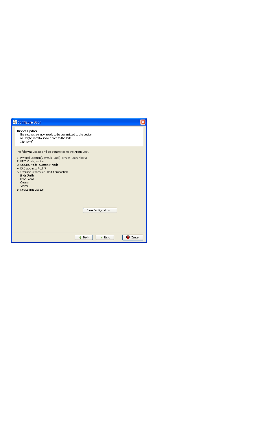
1. The Device Update dialog box shows a summary of the configuration tasks
that normally would be sent to the Lock when continue to the next step in
the wizard. Instead of choosing the next step, click on the button “Save
Configuration…”
Reference Manual
Aperio Technology
40 (91)
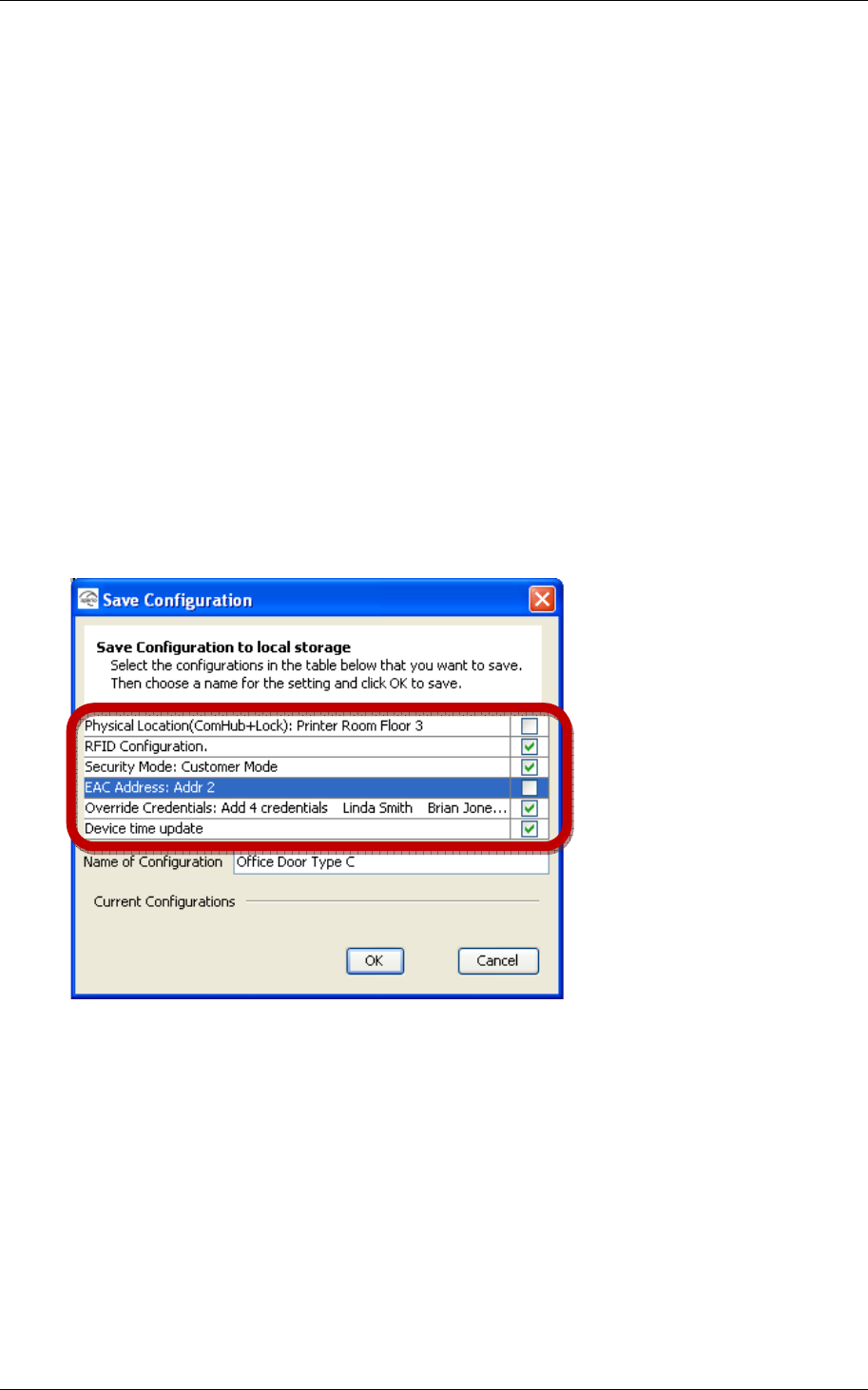
2. The Save Configuration dialog box shows a summary of the configuration
tasks that have been collected during the different steps in the
Configuration Wizard. You can exclude some tasks by simply tick the check
box, as show in the screenshot above.
Recommended tasks to save could be:
o RFID configuration
o Change security mode
o Override credential
o Device time update
o And optionally some advanced features like Battery Alarm, Status
configuration and Locking parameters).
If you choose to save a configuration like the one above, enabling you to
later apply that configuration on other doors, you have to keep in mind
that some configuration tasks, like physical location and EAC address,
need to be configured on a per door basis using the Configuration Wizard
since they are different for each door.
Reference Manual
Aperio Technology
41 (91)
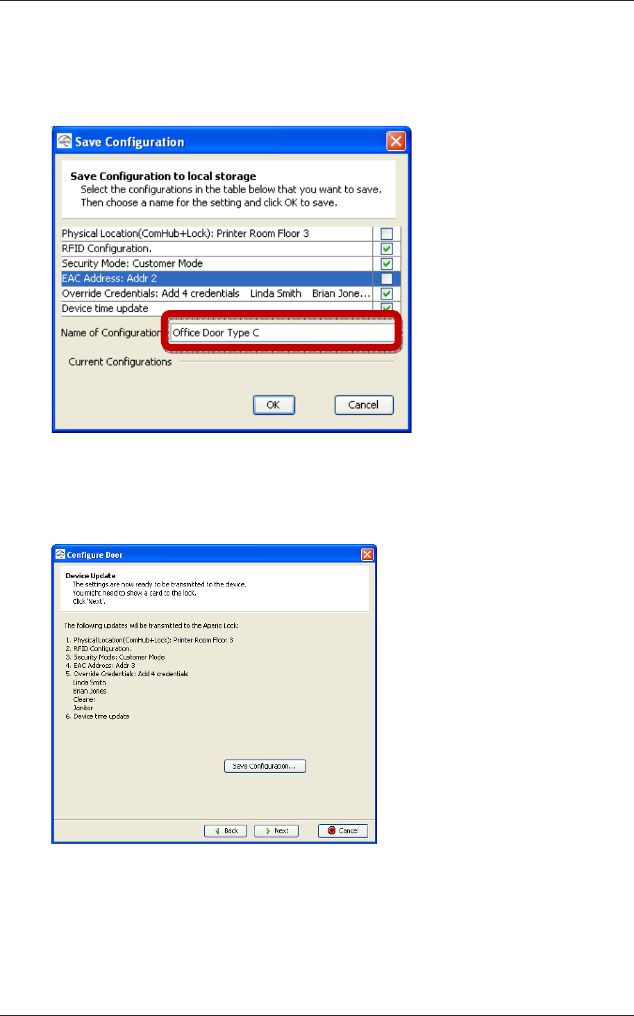
3. Enter a unique and suitable name for this configuration in the Name of
Configuration field. Please choose this name wisely, since it later should be
clear what settings this configuration changes in the door. You could, for
instance, name it according to the different configuration tasks or, if
applicable, use a name that reflects the specific door type.
4. Click OK.
5. Now the configuration is saved in the local storage, and you are back in
the Configuration Wizard. You can choose to update this door with this
configuration or you can choose to cancel the Configure Door operation.
Choosing Cancel does affect the locally stored configuration.
Reference Manual
Aperio Technology
42 (91)
5.7 Perform the device update
For this step you must have an access card available.
Follow these steps to perform the device update:
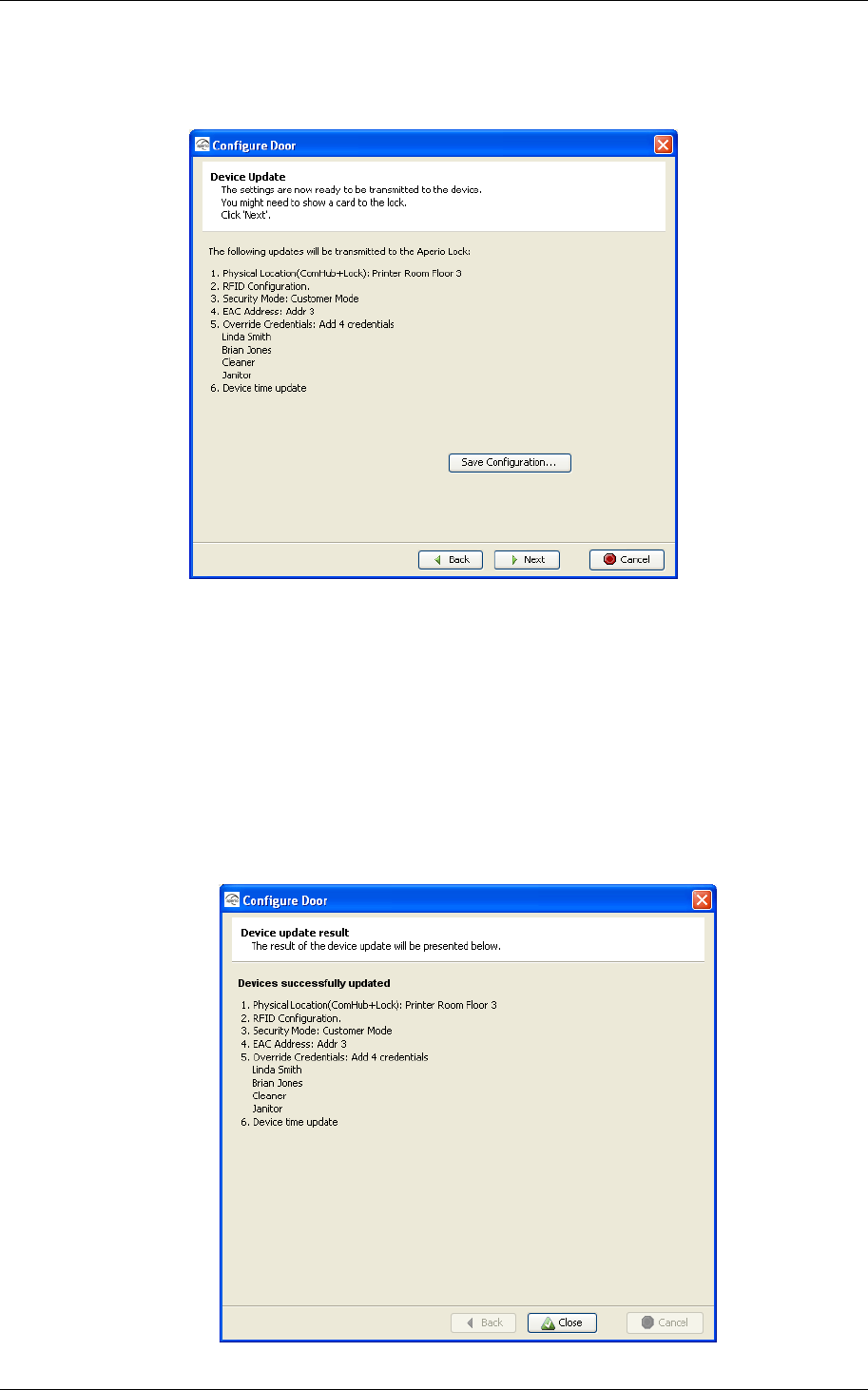
1. The Device Update dialog box shows a summary of the update tasks that
will be performed.
2. Click Next and show a card to the lock to perform the update. You must
show the card within 30 seconds, otherwise the update process will time
out. Note! The time of the lock is automatically set each time you
configure and update the device.
Result: A progress bar shows that the update is being performed. The
Device update result dialog box shows the result of the update when it has
been performed.

Reference Manual
Aperio Technology
43 (91)
3. Click Close.
Reference Manual
Aperio Technology
44 (91)
5.8 Changing the Security Mode
Proper handling of encryption keys is essential to lock security!
If you don’t set the lock in Customer mode, the radio communication will
not be secure and the lock will therefore be vulnerable to intrusion attempts.
Setting of Security mode may either be done as described in chapter 5.3 Update
the door configuration, or separately as described below:
Follow these steps to set the Security mode in another way than via the
configuration wizard:
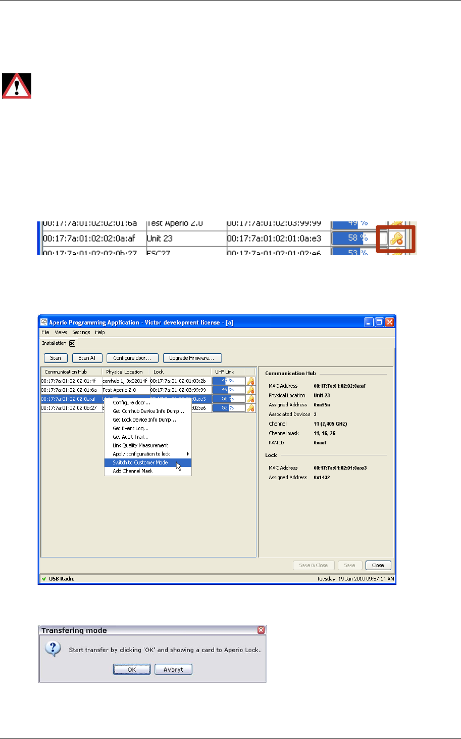
1. In the Installation view, click Scan to perform a scan.
2. Verify that the door is in Manufacturing mode by checking that the key
symbol at the right side of the door in the list has a prohibition sign
attached to it.
3. Right-click the door and select Switch to Customer Mode.
Reference Manual
Aperio Technology
45 (91)
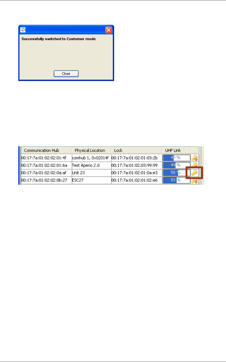
4. Click OK and show an access card to the lock. A progress bar shows that
the transfer is being performed.
5. If the encryption keys is successfully loaded you get a message that
states “Successfully switched to Customer mode”. End with click on Close.
6. Click Scan to perform a new scan.
7. Select the door.
Result: Check the key symbol at the right side of the door to see that the door
has been set to Customer mode.
8. Repeat the steps above for all the doors in the installations you want to
configure.
Alternatively you may use an export file created as described in “5.6
Save the configuration to local storage”.
How to use the export is described in “5.9 How to apply a stored
configuration to a Door”.
Reference Manual
Aperio Technology
46 (91)
5.9 How to apply a stored configuration to a Door
If you performed the steps in “5.6 Save the configuration”, then you may use the
configuration to configure more doors with the same saved settings.
Follow these steps to load a saved configuration to a door:
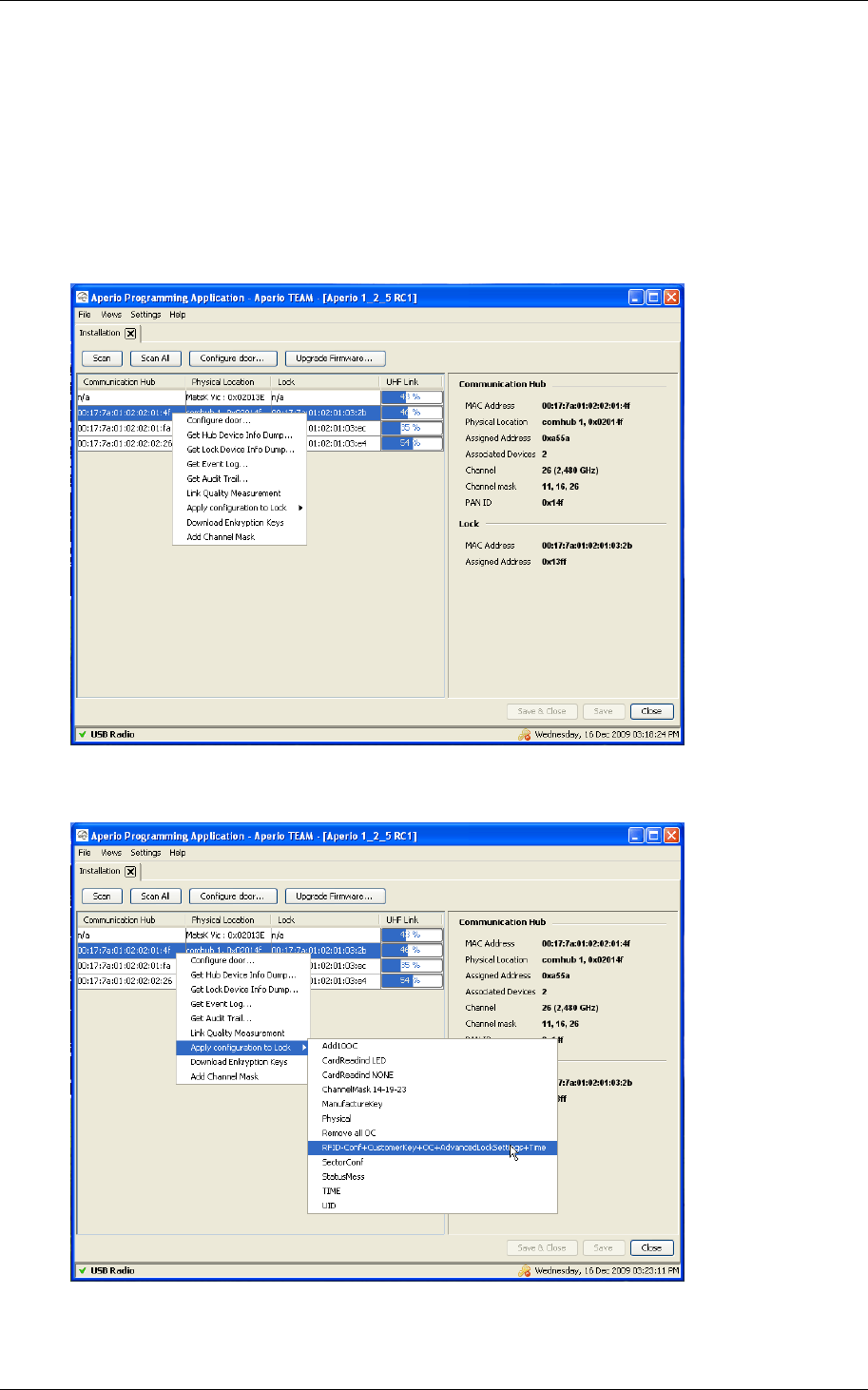
1. In the Installation view, click Scan to perform a scan.
2. Right-click the door and select Apply configuration to Lock
3. Choose the configuration you want to apply to the door.
Reference Manual
Aperio Technology
47 (91)
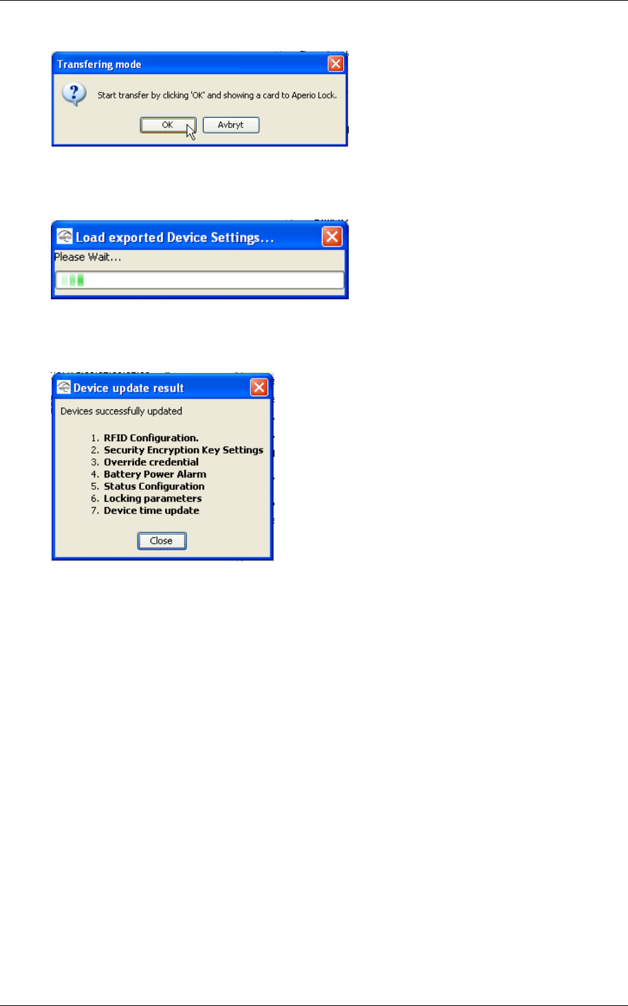
4. Click OK to start the transfer
5. Wait for the transfer to finish.
6. The result is shown.
Click Close to end.
7. Repeat all the steps from beginning in this chapter for every door you
want to configure with a saved configuration
8. Keep in mind that you might have to configure some settings such as
Physical location and EAC address separately as described in 5.3 Update
the door configuration.

Reference Manual
Aperio Technology
48 (91)
5.10 Test after the first configuration
Follow these steps to test that the installation and first configuration of the door
have been performed correctly and that the lock is working:
1. Check that the Communication Hub LED has a steady green light. This
indicates that the installation and configuration have been performed
correctly.
2. Show a card that is configured in the EAC to deny access to the lock.
Result: Access is denied and the lock LED flashes red once.
3. Show a card that is configured in the EAC to grant access to the lock.
Result: Access is granted and the lock LED flashes green once.
5.11 Import and export configurations
The stored configurations discussed in chapter 5.6 and 5.9 can also be exported
to a file so that more than one Aperio Programming Application can share the
same configuration information. When you import an exported configuration you
add it to the local configuration storage and then you can apply that
configuration to a lock as described in chapter 5.9.
Note: When you export a configuration, you can not change the name of the
configuration, only the file name holding the configuration information. Since
configurations can be shared between different Aperio Programming Applications,
it’s preferable that a shared configuration (identified by its unique name) also
has the same meaning on all Aperio Programming Applications. It is therefore
advisable that you choose the name of the configuration wisely when you store
the configuration (as described in chapter 5.6)
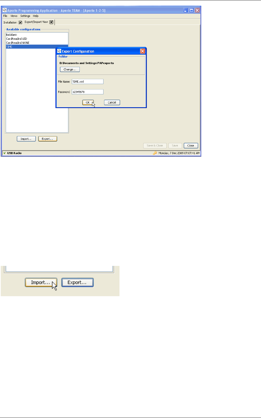
5.11.1 Export Configuration
Open the Export/Import View under the Views menu. The main window lists the
existing stored configurations. Select the configuration that should be exported
to file and click “Export..”.
Reference Manual
Aperio Technology
49 (91)
You need to supply a folder where the exported configuration file will be created,
a file name ending with .xml and a password with at least 8 characters used to
encrypt the information. When the export dialog opens, the export file will be
named after the configuration name and the folder is pointing the current users
home folder, and if that is ok, you only need to supply a valid password. Please
write down the password in a safe place so that you can remember it when you
or someone else would like to import the configuration.
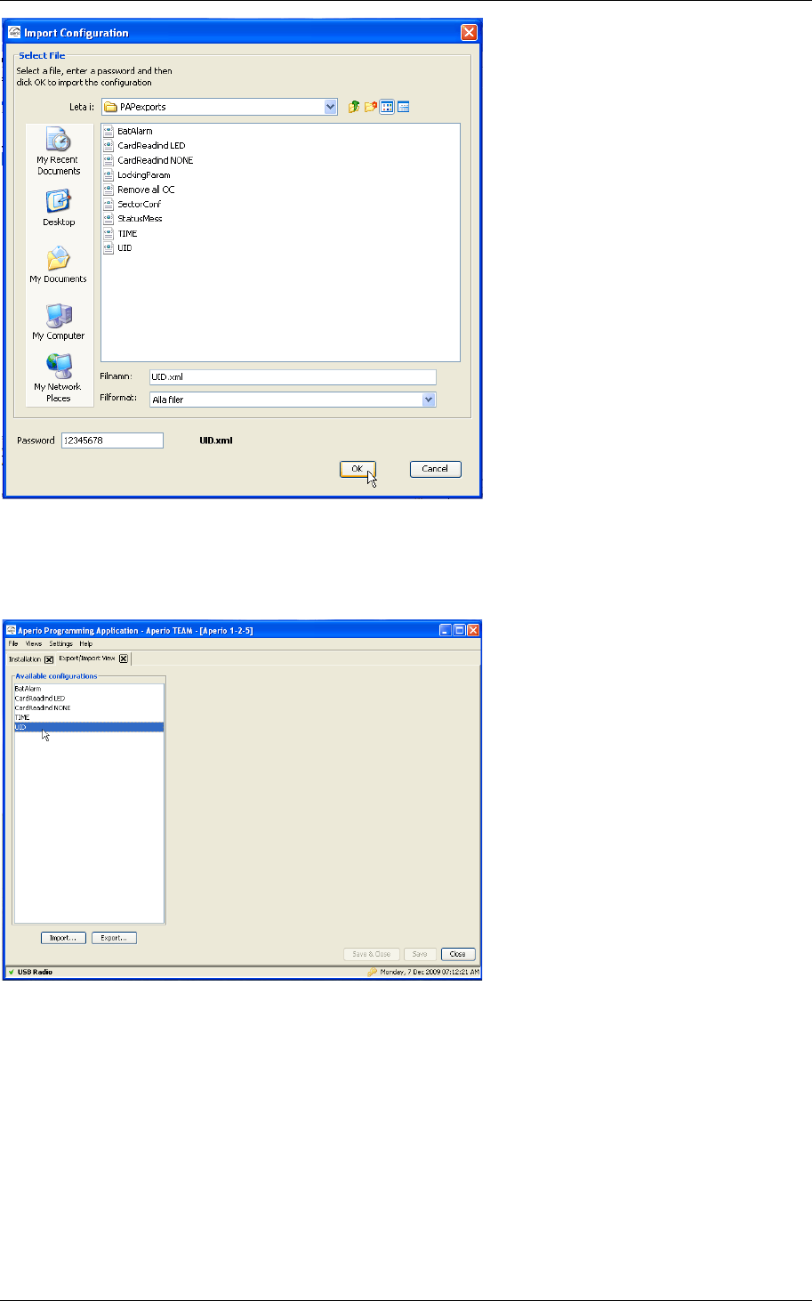
5.11.2 Import Configuration
Importing a configuration takes a previously exported configuration and adds it
to the local configuration storage. Click on the “Import…” button
Reference Manual
Aperio Technology
50 (91)
Open the folder that holds the exported configuration. Select one (should
normally end with .xml). Supply a valid password and click “OK”. The exported
configuration is now added to your local configuration storage.
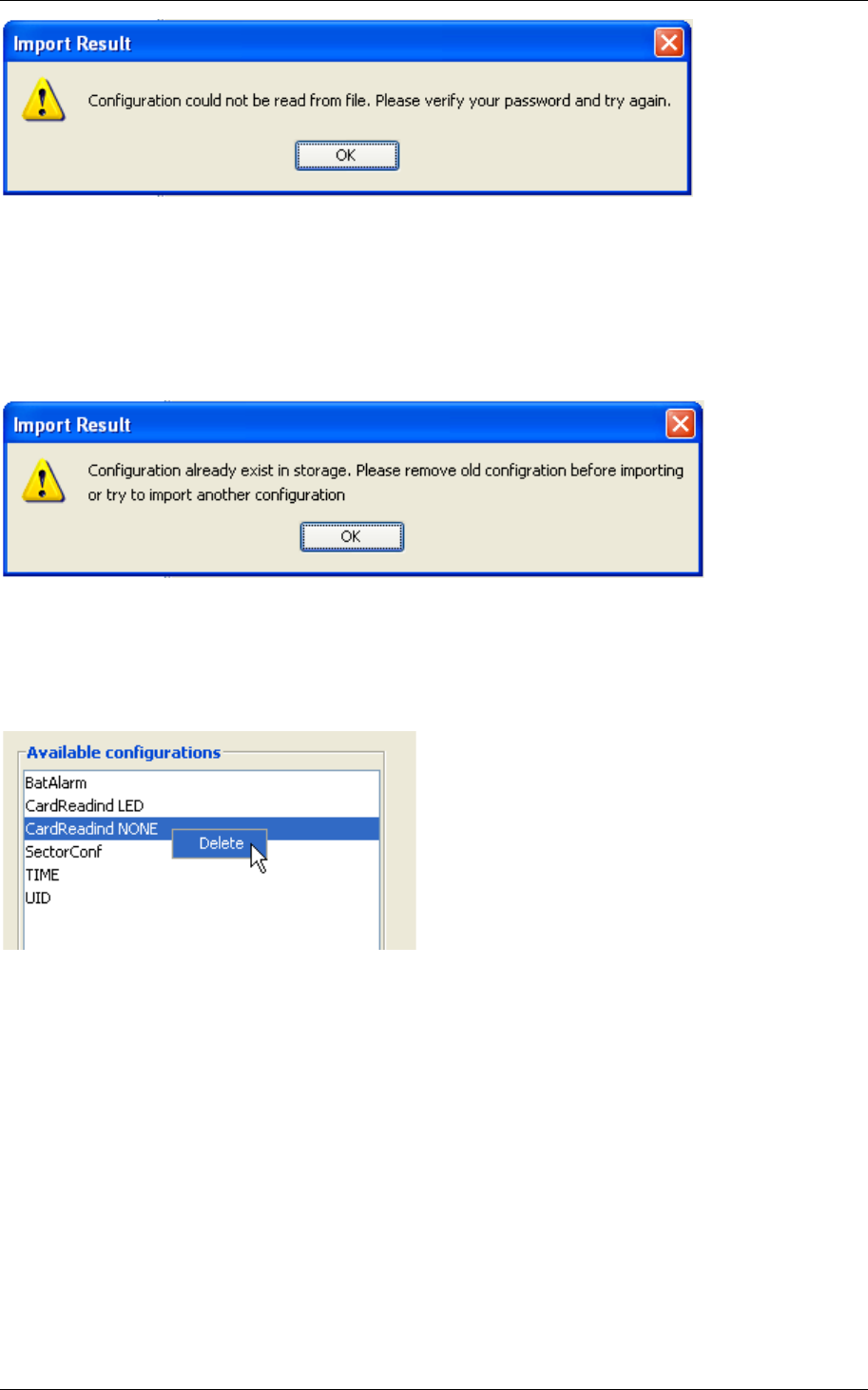
If you supply an invalid password, the content of the exported configuration file
can not be interpreted correctly and the Aperio Programming Application displays
an error message:
Reference Manual
Aperio Technology
51 (91)
Please verify that you have typed in the correct password for this exported
configuration and that you have selected the correct file and try again.
The Aperio Programming Application will not let you import a configuration if it
already exists in the local storage. Note that the configuration is identified by its
name, not the name of the export file.
To be able to import a configuration that already exists in the local storage; you
first need to remove the local configuration. Select the conflicting configuration
and right click and select “Delete” from the popup menu. Now it should be
possible to import the exported configuration.
Reference Manual
Aperio Technology
52 (91)
6. Menus and views
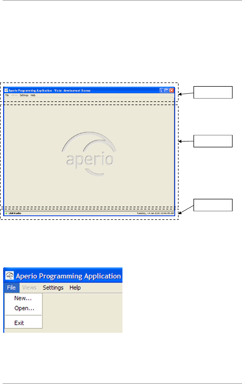
6.1 Main view
The main view of the programming application consists of three areas:
• Menu bar
• View area
• Status bar
See further description of the areas in the sections below.
6.2 File menu
The File menu contains three options:
• New. Create a new installation.
• Open. Open an existing installation.
• Exit. Exit the programming application.
6.3 Views menu
The Views menu contains 3 views:
Menu bar
View area
Status bar
Menu bar
View area
Reference Manual
Aperio Technology
53 (91)
• Installation. Scan for doors and manage door installations. See further
description in section 6.8 Installation View.
• Installation Configuration. Manage the USB radio channel mask and the
updating of device time.
• Default Override Credentials. Manage the default override credentials.
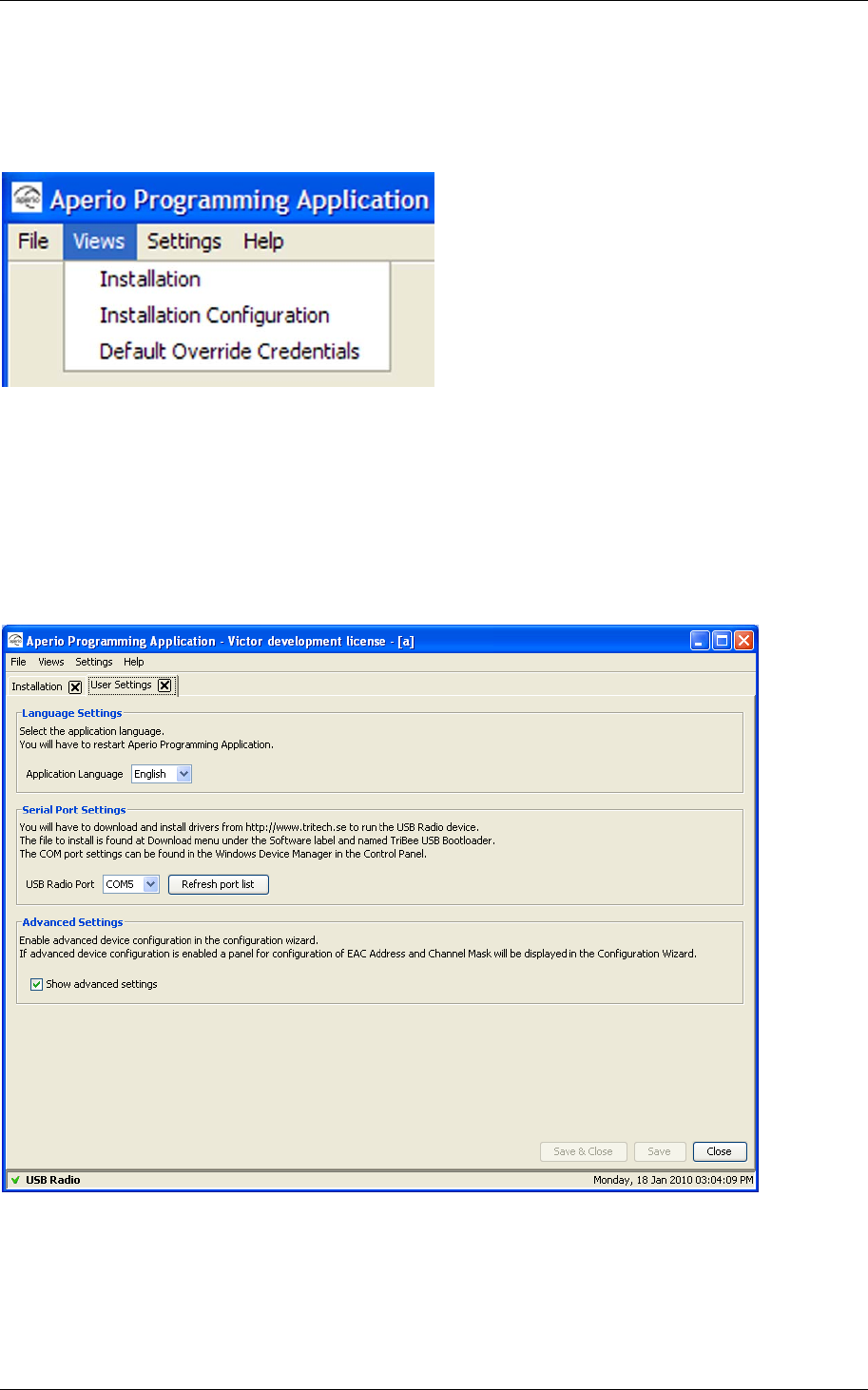
6.4 Settings menu
The User Settings view (in the Settings menu) contains settings that are
applicable to all the installations:
• Language settings
• Serial port settings
• Advanced settings
Reference Manual
Aperio Technology
54 (91)
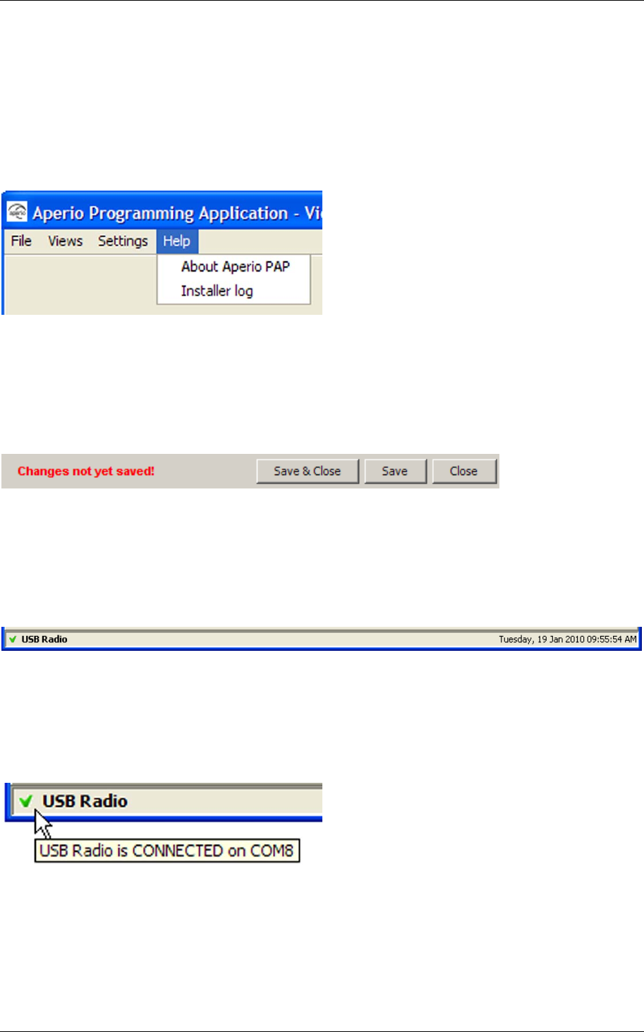
6.5 Help menu
The Help menu contains two options:
• About Aperio Programming Application. Shows license, copyright and
version information.
• Installer log. Shows the actual data transmitted and received from the
application.
6.6 Save and close buttons
If you have unsaved data in any of the views described above this will be
displayed both via a red text and enabled Save and Save & Close buttons. The
data in a view is not saved until you click Save or Save & Close.
6.7 Status bar
The status bar contains the following information:
• USB Radio indication
• Date label.
USB radio indication
USB Radio together with a green check mark indicates that the serial port is ok
and the radio device is ready to transmit data. When you hold the mouse pointer
above this indication you will get information on which com port the radio device
is connected to.
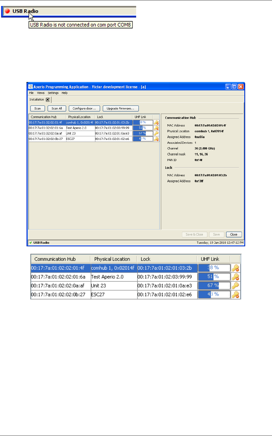
USB Radio together with a red dot indicates that the serial port or the USB radio
device is not ok. When you hold the mouse pointer above this indication you will
get confirmation that the radio device is not connected.
Reference Manual
Aperio Technology
55 (91)
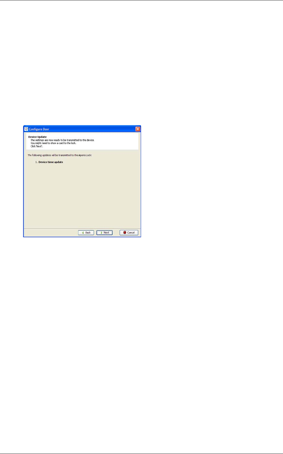
6.8 Installation View
In the Installation View, the installer scans and receives a list of Communication
Hubs that are in reach of the USB radio device.
The found devices are displayed in the list and the following information is
shown:
• Communication Hub. The MAC address of the Communication Hub.
• Physical Location. The physical location specified by the user. This is a
description that may be 20 characters long.
• Lock. Indicates if there is a lock paired with the Communication Hub. If
there is a paired lock the MAC address of the lock is shown. If not, n/a is
shown.
• UHF Link. Indicates the strength of the UHF wireless link (through the USB
Radio device) between the Communication Hub and the Aperio
Programming Application.
• Security Mode. Key symbol and prohibition sign that indicate the security
mode of the device. The security modes are defined according to below.

Reference Manual
Aperio Technology
56 (91)
Customer mode Door is using secure radio communication
with the customer encryption key.
Manufacturing
mode Door is using unsecure radio
communication with the default encryption
key.

Reference Manual
Aperio Technology
57 (91)
7. Maintenance
7.1 Change the battery of the lock
The exact procedure for changing the battery of the lock is described by the
manual for the respective product. The following are some general issues to
consider when changing the battery of an Aperio lock:
1) Always replace the battery with a fresh one. The battery alarm detection
algorithm is dependent on that the battery has full capacity when the lock
is powered up.
2) After removing the old battery, show any card to the lock to make sure
that all energy is drained from the internal storage capacitors thus
ensuring a proper power up.
3) Prepare yourself for the battery replacement operation. If the lock is left
without battery for too many seconds, the time is lost and it is required to
use the Aperio Programming Application to set it right again (see 7.2 Set
the time of the lock).
4) After inserting the new battery, check the LED flashing for a successful
POST (see 2.9 Lock self test LED indication). If the battery is not accepted
as new, there will be an error indication instead of the POST flashes.
Remember: Remove old _ Show a _ Insert new _ Check
battery card battery POST
Reference Manual
Aperio Technology
58 (91)
7.2 Set the time of the lock
Follow these steps to set the time of the lock:
1. Open the installation for the lock in the Aperio programming application
and click Scan.
2. Select the door in the scan result table.
3. Open Views–Installation Configuration and check that Update device time
during door configuration is checked. Close the Installation Configuration
view.
4. Click Configure door. Click Next several times and go through the
configuration wizard without making any changes. Result: The Device
Update dialog box is opened.
5. Click Next and show a card to the lock to update the time of the lock. You
must show the card within 30 seconds, otherwise the update process will
time out. Note! The time of the lock will now be automatically set each
time you configure and update the device.
Result: A progress bar shows that the update is being performed. The
Device update result dialog box shows the result of the update when it has
been performed.
6. Click Close.
Reference Manual
Aperio Technology
59 (91)
7.3 Firmware upgrade
This chapter describes how to upgrade the system to a new release.
7.3.1 Preconditions
1. Ensure that you are using the latest version of the Aperio Programming
Application. If not – install the latest Aperio Programming Application
according to Fel! Hittar inte referenskälla..
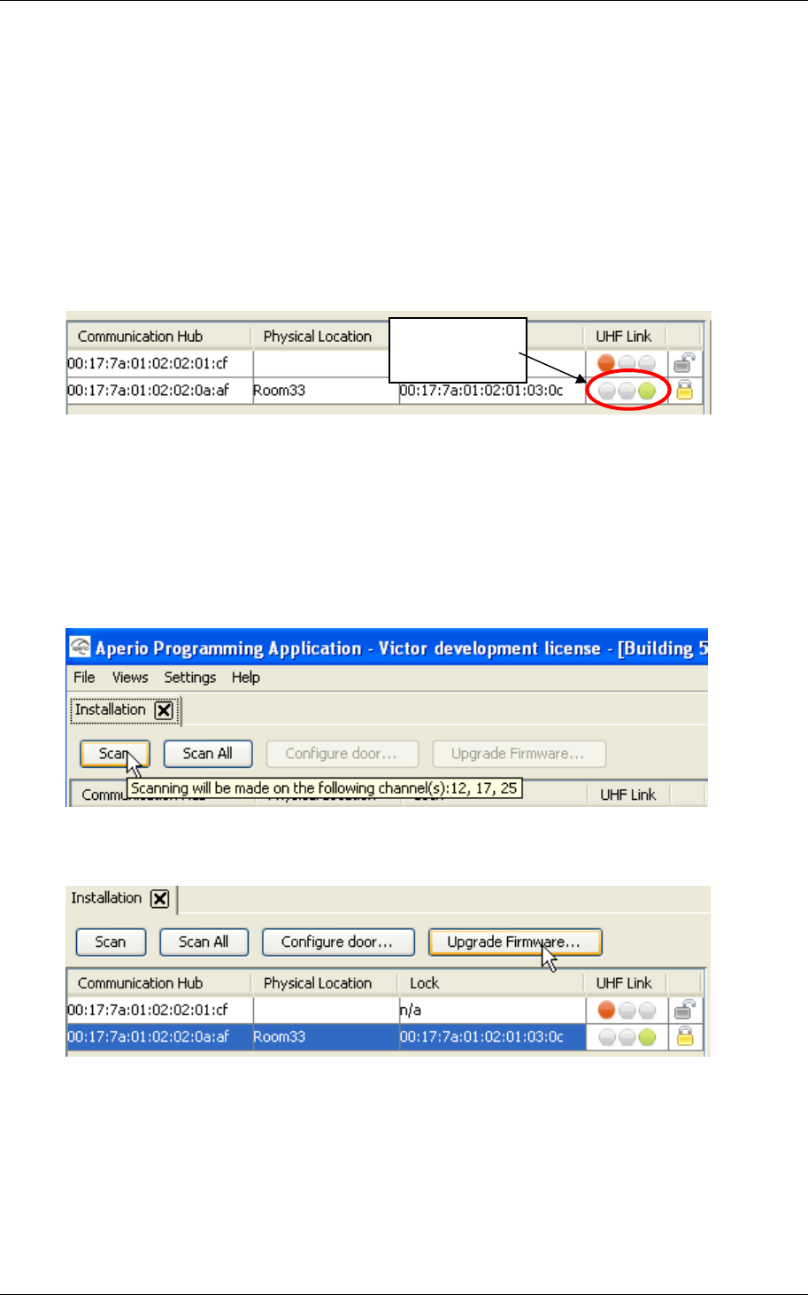
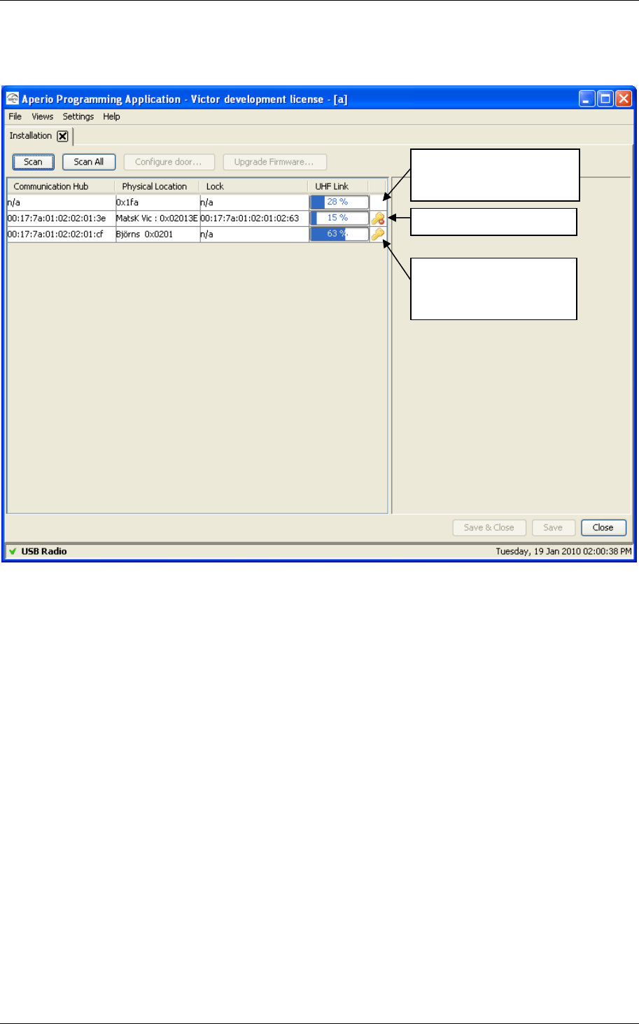
2. Check communication. Check on the UHF Link indicator that the signal
strength indicator is good enough to be able to perform an upgrade. If you
have bad signal strength you will not be able to perform the upgrade.
3. Ensure that you have an afw file with firmware that is compatible with the
units to be upgraded. Downloading of wrong firmware may make the
unit unusable.
7.3.2 Upgrading
4. Perform a scan in the Aperio Programming Application.
5. Select the door to upgrade and click on Upgrade Firmware…
Good signal
strength
Reference Manual
Aperio Technology
60 (91)
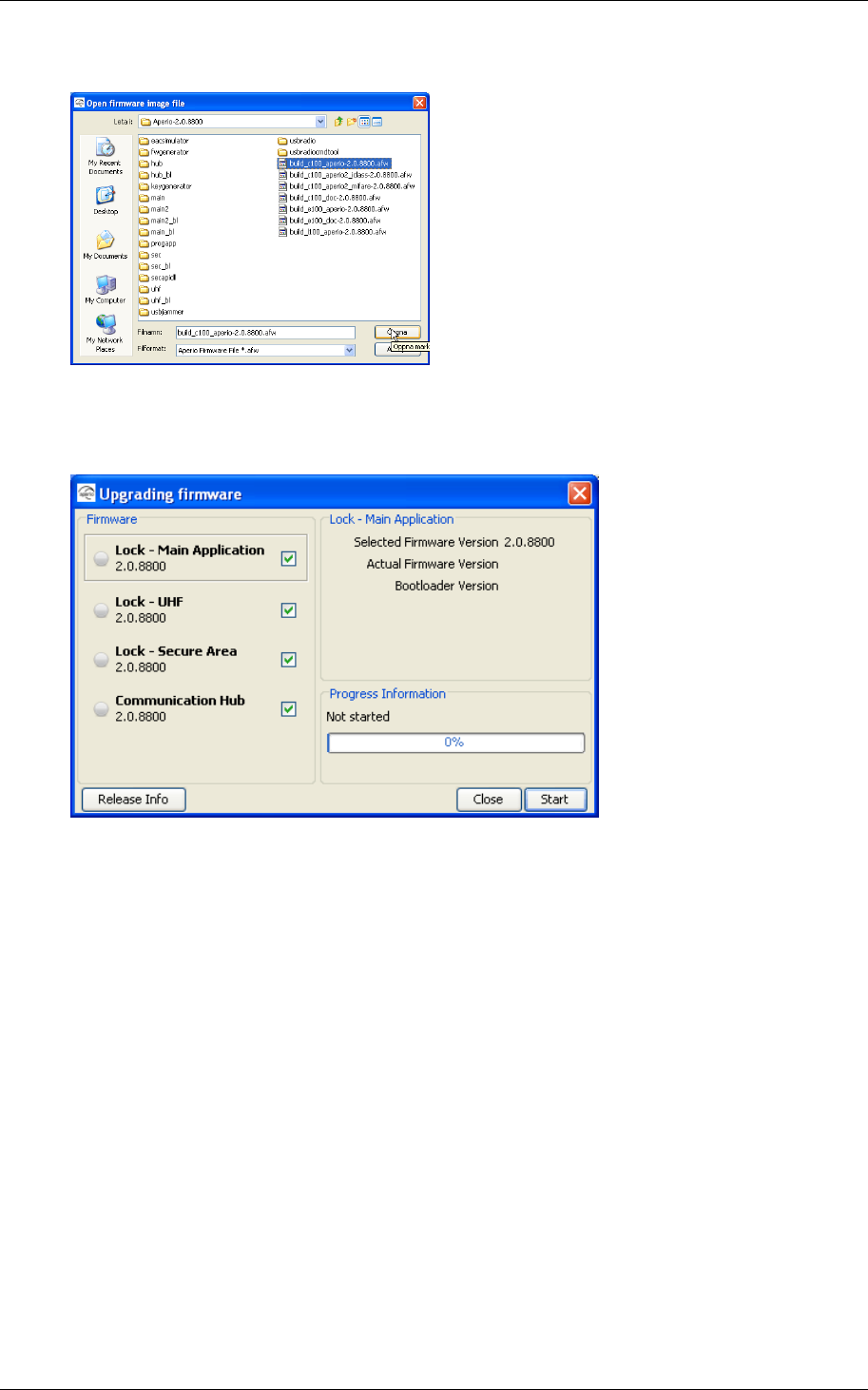
6. Select the .afw file and click open.
7. The firmware upgrade window with a list of the units that may be
upgraded is shown.
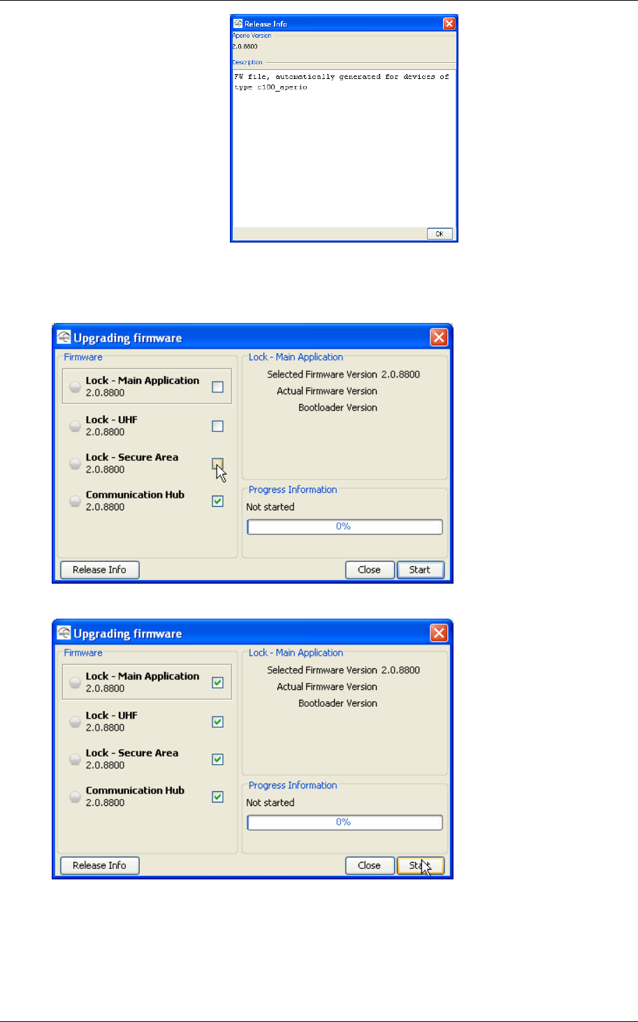
8. Click on Release Info to get more information about the selected .afw file.
Important: Check in the release info window that the .afw file used at
upgrade is consistent with the lock/cylinder type. A C100 .afw file must be
used with cylinder locks. An E100 .afw file must be used with escutcheon
locks.
No sanity check is done by the Aperio Programming Application before the
firmware download starts.
Reference Manual
Aperio Technology
61 (91)
9. Close the release Info window by pressing the OK button.
10.All firmware is selected to be downloaded by default. Uncheck firmware
that you do not wish to download.
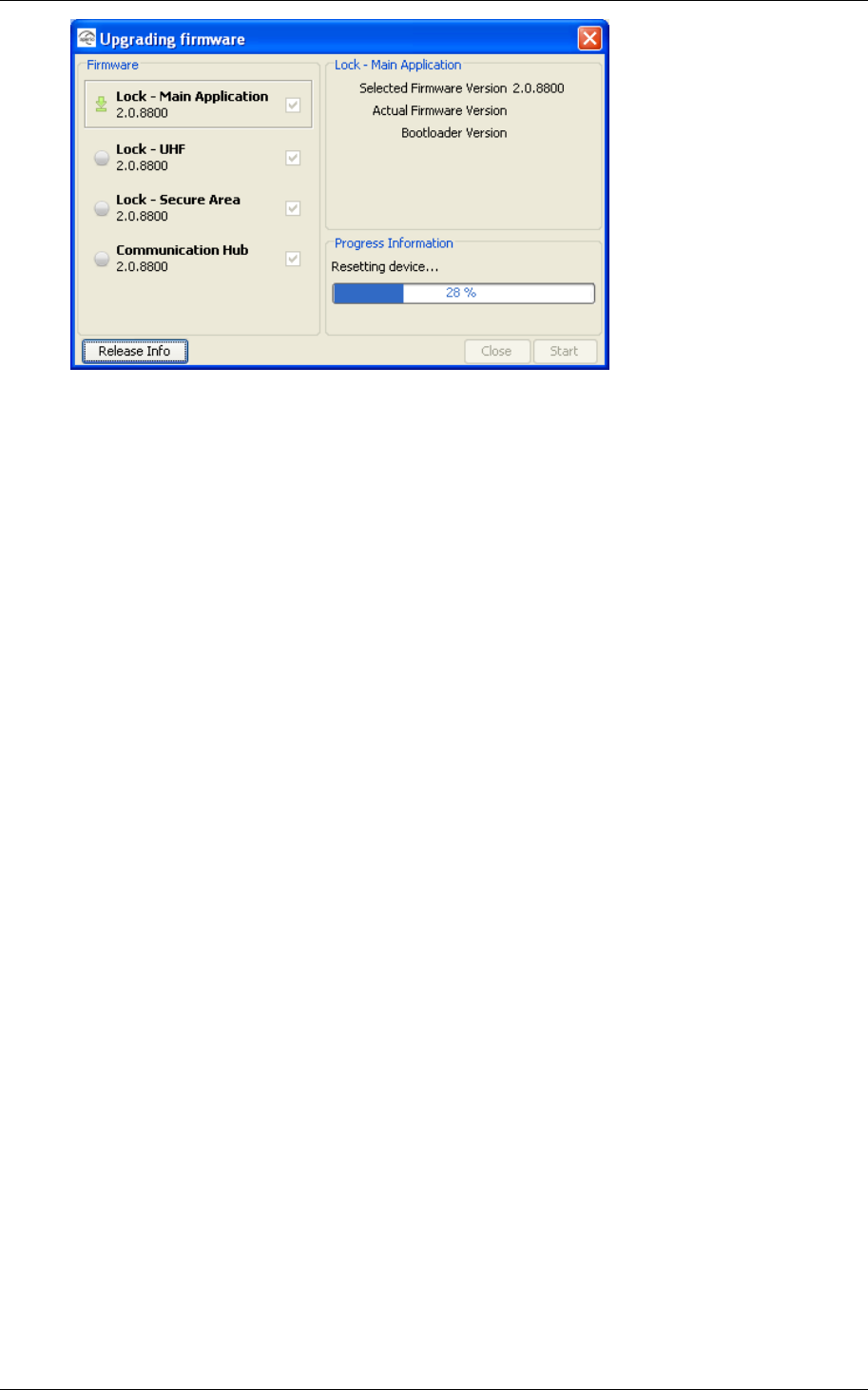
11.Click on Start to begin the upgrade.
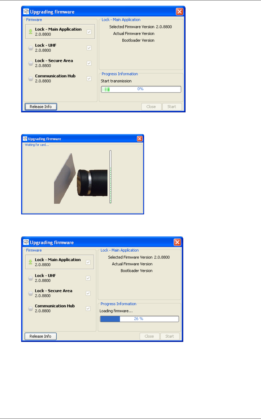
12.The upgrade will start with the first selected firmware in the list. A green
arrow will indicate the firmware being upgraded.
Reference Manual
Aperio Technology
62 (91)
13.If you are upgrading a lock you will be prompted to show a card to the
lock before the download starts.
14.The Aperio Programming Application starts downloading the firmware to
the device.
15.After that the device is resetting.
When the device starts again Aperio Programming Application is standby
waiting to collect version information.
Reference Manual
Aperio Technology
63 (91)
Reference Manual
Aperio Technology
64 (91)
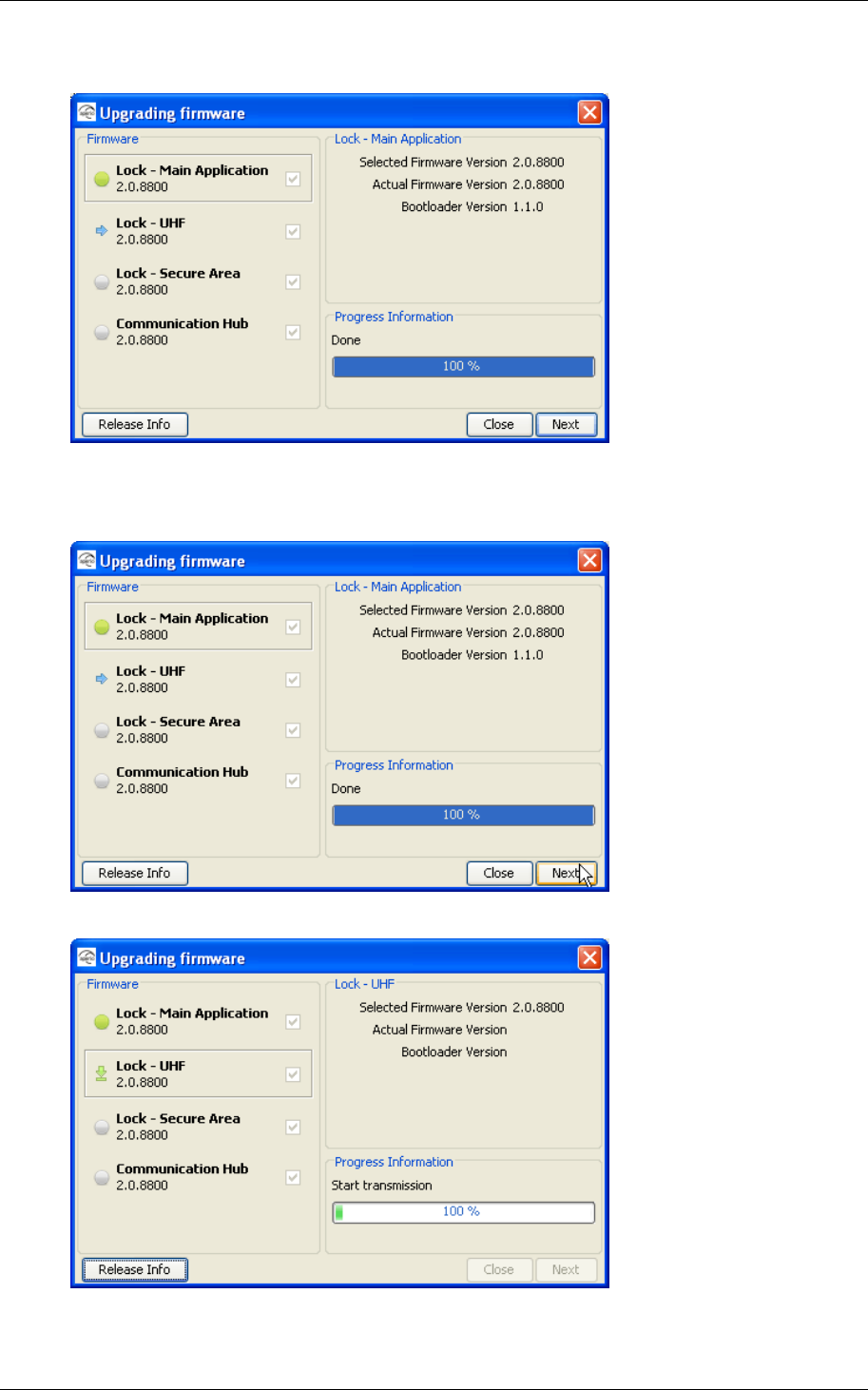
16.The version information of the device is shown.
17.Click the Next button to continue with the next firmware in the list.
Click the Close button if you do not wish to continue the firmware
download.
18.The download starts for the next firmware.
19.Continue downloading the other firmware in the same way as above until
all firmware is downloaded.
Reference Manual
Aperio Technology
65 (91)
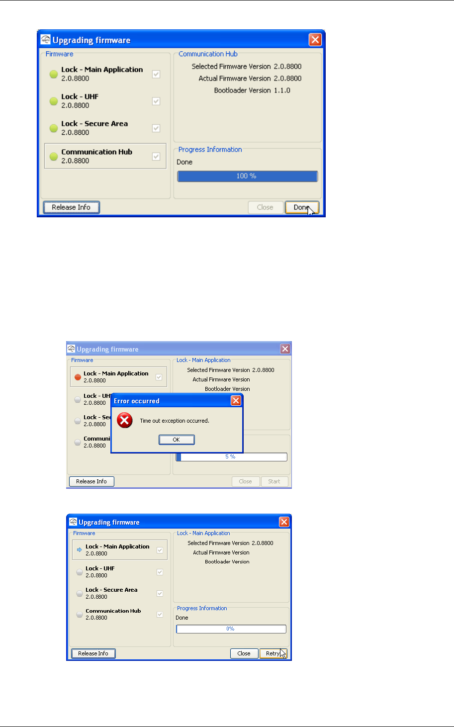
20.Click the Done button to close the window.
7.3.2 Update failure
1. A failed update is typically due to bad radio conditions. The work around is
to move the USB Radio closer to the Communication Hub and try update
again. See 7.4 Establish communication procedure Close the error
message window by clicking OK.
2. Click Retry to try the upgrade again.
Reference Manual
Aperio Technology
66 (91)
7.4 Establish communication procedure
This describes a procedure for how to establish communication with a door.
a. Check encryption keys. If at repeated scan the physical location is
displayed while MAC addresses and security mode are not, there is an
encryption key mismatch. The door is using other encryption key than the
one used in the Aperio Programming Application installation.
Verify that you are using a Programming Application installation with the
correct encryption key. If not open or create an installation with the
correct encryption key and try to scan for locks. If you are using the
correct encryption keys try Check radio link below.
b. Check radio link. If the communication between Programming
Application/USB Radio and Communication Hub or lock/cylinder works
poorly also when the MAC address of this Communication Hub is
sometimes displayed at scan, the problem is not related to encryption
keys. A probable cause is bad radio conditions or limited radio range.
Try moving the USB radio closer to the Communication Hub or moving the
USB radio to a higher location. This can be done by moving the entire
Door using other encryption
key than the Programming
Application installation.
Doo
r
in
Manufacturing mode.
Door in Customer mode
using same customer key as
the Programming Application
installation.

Reference Manual
Aperio Technology
67 (91)
Programming Application PC or by use of an A-A USB extension cable to
distance the USB radio from the Programming Application PC.
Reference Manual
Aperio Technology
68 (91)
8. Troubleshooting
8.1 Problems and solutions
The table below shows possible problems when using the Aperio technology, and
how to solve them:
Problem
indication Cause Action
During installation of the programming application
Not possible to
install the Aperio
Programming
Application
The Tritech USB
driver and the
Aperio software
are not available
or saved in the
appropriate
folders on your
laptop.
• Download the Tritech USB driver from
http://www.tritech.se.
• Save the Tritech USB driver and the Aperio
software in the appropriate folders of your
laptop. See section 3.5 Install the
programming application
Follow these steps to install the programming
application:
7. Unpack the Aperio distribution file (ex.
progapp-x.y.z.zip), including the setup.exe file,
in a temporary folder.
8. Run the setup.exe file. Result: The Aperio
programming application is installed.
9. Click Start–All Programs–Aperio Programming
Application–Start.
10.At startup the Aperio Programming Application
checks that the correct java version is
installed. If the correct version is not installed
the following will occur:
c) A warning will be shown. Click OK to close
the window.
d) You are redirected to a page from where
you can download the required Java
version. Install the required version and
restart the Aperio Programming Application
according to Fel! Hittar inte referenskälla.
above.
e) Browse for the license file (.alc), select it
and click OK. Result: The Aperio
Programming Application starts. Note! The
license file should be delivered in a
Reference Manual
Aperio Technology
69 (91)
separate e-mail or on a USB memory stick.
11.If this is the first time you install the Aperio
Programming Application, you need to follow
the steps in chapter 3.6 Install the USB radio
driver before you can start the program.
12.
13.
14.
15.
16.
17.
• 3.6 Install the USB radio driver and Fel! Hittar inte
referenskälla..
Communication
between the USB
radio device and
the programming
application fails
The wrong USB
port is
configured.
Update the port list. See section 3.5 Install the
programming application
Follow these steps to install the programming
application:
18.Unpack the Aperio distribution file (ex.
progapp-x.y.z.zip), including the setup.exe file,
in a temporary folder.
19.Run the setup.exe file. Result: The Aperio
programming application is installed.
20.Click Start–All Programs–Aperio Programming
Application–Start.
Reference Manual
Aperio Technology
70 (91)
21.At startup the Aperio Programming Application
checks that the correct java version is
installed. If the correct version is not installed
the following will occur:
f) A warning will be shown. Click OK to close
the window.
g) You are redirected to a page from where
you can download the required Java
version. Install the required version and
restart the Aperio Programming Application
according to Fel! Hittar inte referenskälla.
above.
h) Browse for the license file (.alc), select it
and click OK. Result: The Aperio
Programming Application starts. Note! The
license file should be delivered in a
separate e-mail or on a USB memory stick.
22.If this is the first time you install the Aperio
Programming Application, you need to follow
the steps in chapter 3.6 Install the USB radio
driver before you can start the program.
23.
24.
25.
26.
Reference Manual
Aperio Technology
71 (91)
27.
28.
3.6 Install the USB radio driver, step 8.
The New hardware
found dialog box is
opened (in
Windows) when
inserting the USB
radio device
Missing driver. Install the driver of the USB radio device. See section
3.5 Install the programming application
Follow these steps to install the programming
application:
29.Unpack the Aperio distribution file (ex.
progapp-x.y.z.zip), including the setup.exe file,
in a temporary folder.
30.Run the setup.exe file. Result: The Aperio
programming application is installed.
31.Click Start–All Programs–Aperio Programming
Application–Start.
32.At startup the Aperio Programming Application
checks that the correct java version is
installed. If the correct version is not installed
the following will occur:
i) A warning will be shown. Click OK to close
the window.
j) You are redirected to a page from where
you can download the required Java
version. Install the required version and
restart the Aperio Programming Application
according to Fel! Hittar inte referenskälla.
above.
k) Browse for the license file (.alc), select it
and click OK. Result: The Aperio
Programming Application starts. Note! The
license file should be delivered in a
separate e-mail or on a USB memory stick.
33.If this is the first time you install the Aperio
Programming Application, you need to follow
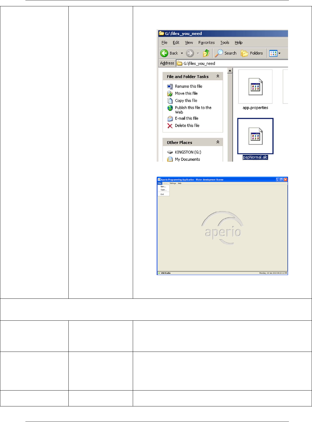
Reference Manual
Aperio Technology
72 (91)
the steps in chapter 3.6 Install the USB radio
driver before you can start the program.
34.
35.
36.
37.
38.
39.
3.6 Install the USB radio driver.
During door installation and update
Not possible to pair
Communication
Hub and lock
You are using a
card configured
as an override
credential.
Use a card that is not on the override credentials list.
Not possible to add
default override
credentials
No default
override
credentials are
configured for the
installation.
Add the credentials one by one in the door
configuration wizard.
The device update
fails You have not
shown the card to Perform device update again and show the card to
the lock within 30 seconds.

Reference Manual
Aperio Technology
73 (91)
the lock within 30
seconds.
Not possible to
open a version 1.0
installation in
version 1.1
It is not possible
to upgrade the
Aperio
programming
application.
Create a new installation with the same encryption
key and create the default override credentials list.
The
Communication
Hub has only one
channel in its
channel mask
Link
measurement has
failed.
Reconfigure the channel mask via the advanced door
configuration. See section 8.2 Change the channel
mask.

Reference Manual
Aperio Technology
74 (91)
Problem indication Cause Action
During scanning
The Communication Hub
and lock are not found when
scanning = no connection
between the programming
application/laptop and the
Communication Hub
• All channels are busy.
• The programming
application and the
Communication Hub
have different channel
masks.
• The Communication
Hub is not working.
• The Communication
Hub is not powered.
1. Click Scan again.
2. Click Scan all.
3. Change the channel mask.
See section 8.2 Change
the channel mask.
None or not all of the
Communication Hubs are
found when scanning
• The Communication
Hub(s) are out of
range.
• The Communication
Hub(s) are operating
with a different
channel mask.
• The Communication
Hub(s) are not
powered.
• Too many
Communication Hubs
are using the same
channel.
See footnote 1
1. Click Scan again.
2. Click Scan all.
• Change the channel mask
in the installation
configuration view of the
Aperio programming
application. See section
8.2 Change the channel
mask.
• Change the channel mask
in the devices (done by
advanced door
configuration). See section
8.2 Change the channel
mask.
• Temporary reduce the
number of powered up
Hubs within radio range
during configuration.
1
1 Aperio Hubs is default configured to select the best channel out of three possible, if the
selected channel is disturbed a new channel selection will be done automatically. An
Aperio system with many Hubs normally distribute themselves on different channels but
a synchronized power up of all Hubs may cause all Hubs to initially choose the same
channel.
(Note that this problem do not affect performance of already installed and paired
lock/cylinders and Hubs, only Programming Application scan functionality is affected)

Reference Manual
Aperio Technology
75 (91)
Problem indication Cause Action
n/a is shown for the
installation in the
Communication Hub field
and in the Lock field of the
scan result table
• The Communication
Hub and/or
Communication Hub
paired with a lock
belongs to another
installation and has
another encryption
key.
• The lock is not paired
with the
Communication Hub.
• Switch installation or
create a new installation
with the correct encryption
key.
• Pair the lock and
Communication Hub in the
Configure door wizard of
the programming
application.
During normal operation
The Communication Hub
LED is flashing red once =
no connection between the
lock and the Communication
Hub
• The lock and
Communication Hub
are not paired.
• The lock and the
Communication Hub
have different channel
masks.
• The battery of the
lock has run out.
• Click Scan again.
• Pair the lock and
Communication Hub in the
Configure door wizard of
the programming
application.
• Change the channel mask.
See section 8.2 Change
the channel mask.
• Change the battery of the
lock. See section 7.1
Change the battery of the
lock.
The Communication Hub
LED is flashing red twice =
no connection between the
EAC system and the
Communication Hub
• The EAC address is
not properly
configured in the
Communication Hub.
• The EAC system is not
properly configured.
Configure the EAC address using
the programming application.
See section 5.3 Update the door
configuration, step 16-17.

Reference Manual
Aperio Technology
76 (91)
Problem indication Cause Action
Unstable radio
communication between
lock and Communication
Hub
• Poor radio link
quality.
• The lock and the
Communication Hub
have different channel
masks.
• Measure the radio link.
See section 8.3 Measure
the radio link.
• Change the channel mask.
See section 8.2 Change
the channel mask.
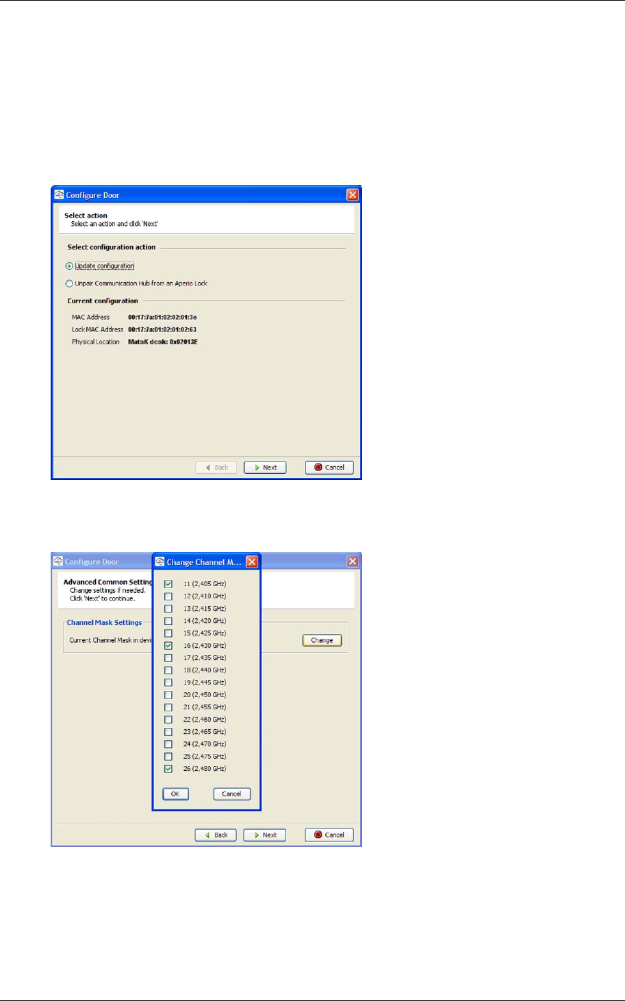
Reference Manual
Aperio Technology
77 (91)
8.2 Change the channel mask
Follow these steps to change the channel mask for the Communication Hub and
lock:
1. Open the applicable installation in the Aperio programming application and
click Scan.
2. Select the door in the scan result table and click Configure door.
3. Click Next five times to go to the Advanced Common Settings dialog box.
Click Change.
4. Change the channel mask and click OK. Note! Three channels are
recommended.
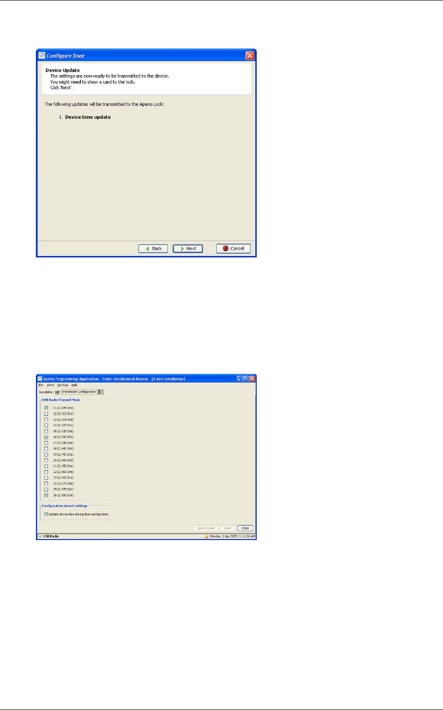
Reference Manual
Aperio Technology
78 (91)
5. Click Next two times. Result: The Device Update dialog box is opened.
6. Click Next and show a card to the lock to perform the update. You must
show the card within 30 seconds, otherwise the update process will time
out. Result: A progress bar shows that the update is being performed.
The Device update result dialog box shows the result of the update when it
has been performed.
7. Click Close.
8. Open Views–Installation Configuration.
9. In the USB Radio Channel Mask field, select the same channels for the
USB radio device as in step 4 above.
10.Click Save & Close.
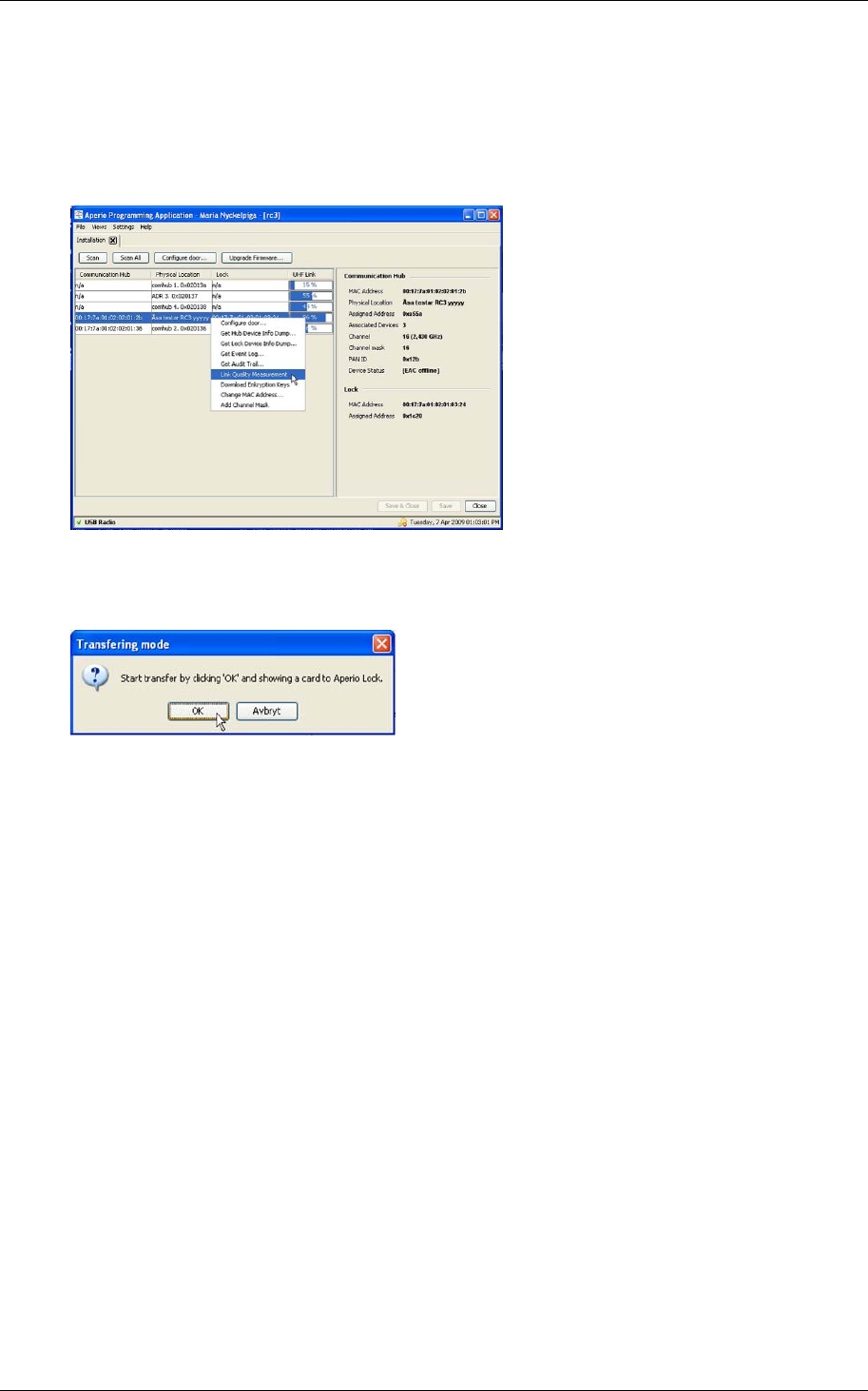
Reference Manual
Aperio Technology
79 (91)
8.3 Measure the radio link
Follow these steps to measure the radio link:
1. Open the applicable installation in the Aperio programming application and
click Scan.
2. Select a door in the scan result table, right-click it and select Link Quality
Measurement.
3. Click OK and show an access card to the lock. The Measure Link Quality
progress bar shows that the measurement is being performed. Result:
The result of the measurement is shown.
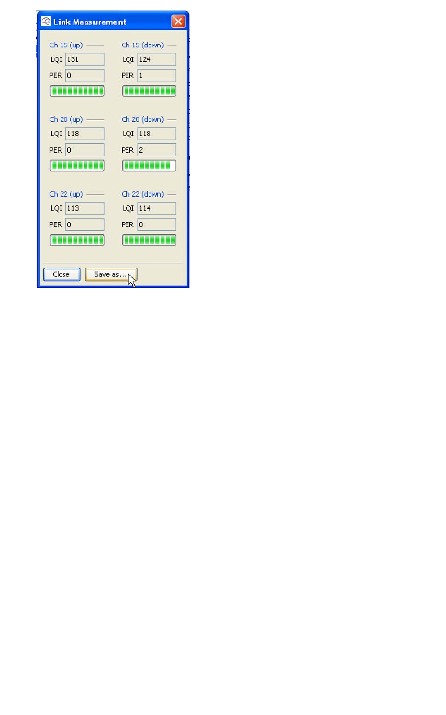
Reference Manual
Aperio Technology
80 (91)
4. Click Close or click Save as to save the link measurement data to a file.
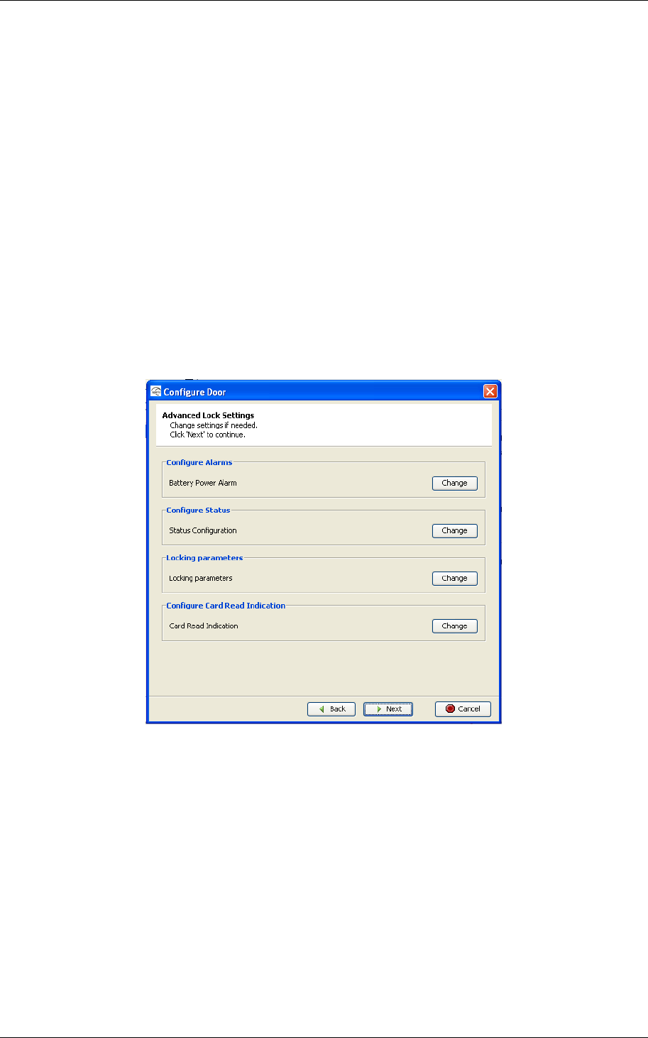
Reference Manual
Aperio Technology
81 (91)
8.4 Advanced Lock Settings
When configuring a door you have the option to configure advanced lock
settings.
These are
battery power alarm – configuration of the battery level that triggers an
alarm and with what interval the battery in the lock should be checked.
status messages and report intervals – configuration of which statuses
the message should contain and with what interval the message should be
sent.
locking time parameters – configuration of the time the lock should be
open, try to open, and after what time a close alarm should be sent to the
event log.
card read indication – Configure the audio-visual card reading
indication. This could typically be: None, LED or in some hardware Buzzer.
8.4.1 Battery Power Alarm
The battery power alarm is sent from the lock to the EAC system and is used to
indicate when it is time to replace the battery. It may be necessary to configure
the alarm triggering depending on the type of battery used and the surrounding
temperature, e.g. in cold surroundings the battery runs out faster.
The alarm trigger can be configured to either of Early, Normal or Late and the
check interval between 5 – 255 minutes.
Default values are Normal and 60 minutes interval.
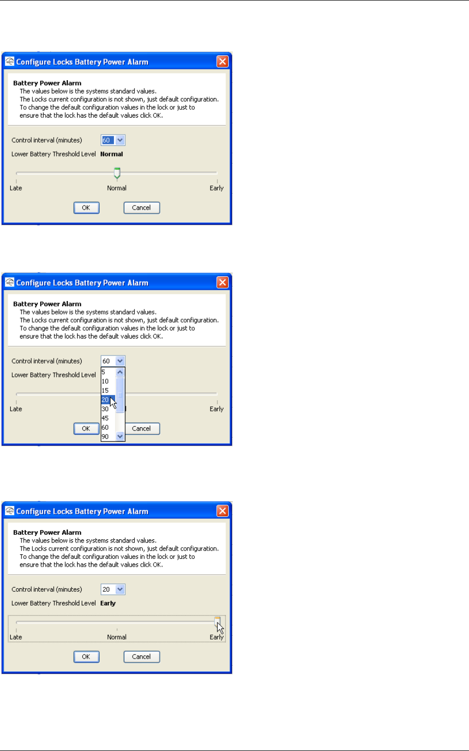
Reference Manual
Aperio Technology
82 (91)
Follow these steps to configure the battery alarm in the configuration wizard:
1. Click Change
2. The default configuration is shown, if you want to keep it just click OK. If
you want to change to something else follow the next steps…
3. To change the control interval use the drop down and choose the
appropriate time.
4. To change alarm trigger threshold level use the slider.
5. Confirm with OK
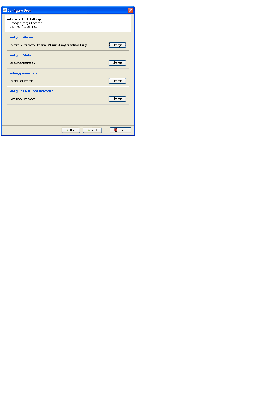
Reference Manual
Aperio Technology
83 (91)
You will see selected values in the configuration wizard.
8.4.2 Status configuration
You can configure if you want the lock to send status messages.
The message can include one or more of the following types of statuses:
Low power – if the battery has reached the level when battery power alarm is
triggered.
Real time clock failure – not used.
Serious failure – not used.
ComHub offline – not used.
EAC offline – if the EAC has gone offline from the Hub, e.g. the EAC HW is
turned off, or the Hub is physically disconnected from the loop and doesn’t detect
the EAC.
Lock offline – if the lock has gone offline from the Hub.
Radio disturbance detected – if radio disturbances is detected.
Default setting for status message is 60 minutes interval for “Low power” and
“Real-time clock failure”.
Follow these steps to configure the status messages in the configuration wizard:
1. Click Change
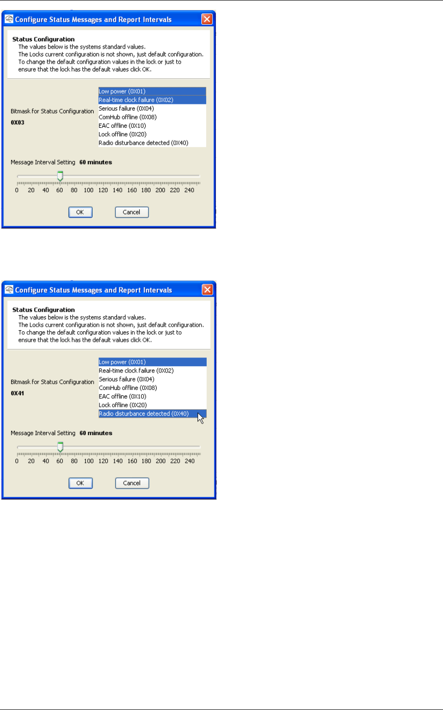
Reference Manual
Aperio Technology
84 (91)
2. The default configuration is shown, if you want to keep it just click OK. If
you want to change to something else follow the next steps…
3. To change the status the message should contain keep <Ctrl> down and
choose from the list as shown.
In the parenthesis, to the right of the status, you see the bit mask (in
hexadecimal notation) that will be created for the status message.
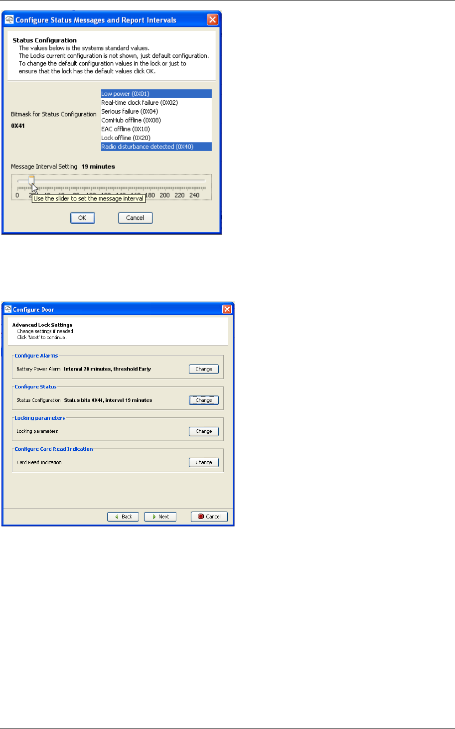
Reference Manual
Aperio Technology
85 (91)
4. To change the message interval use the slide bar and choose the time for
how often the status message should be sent.
5. Confirm with OK
You will see the selected bit mask in the configuration wizard.
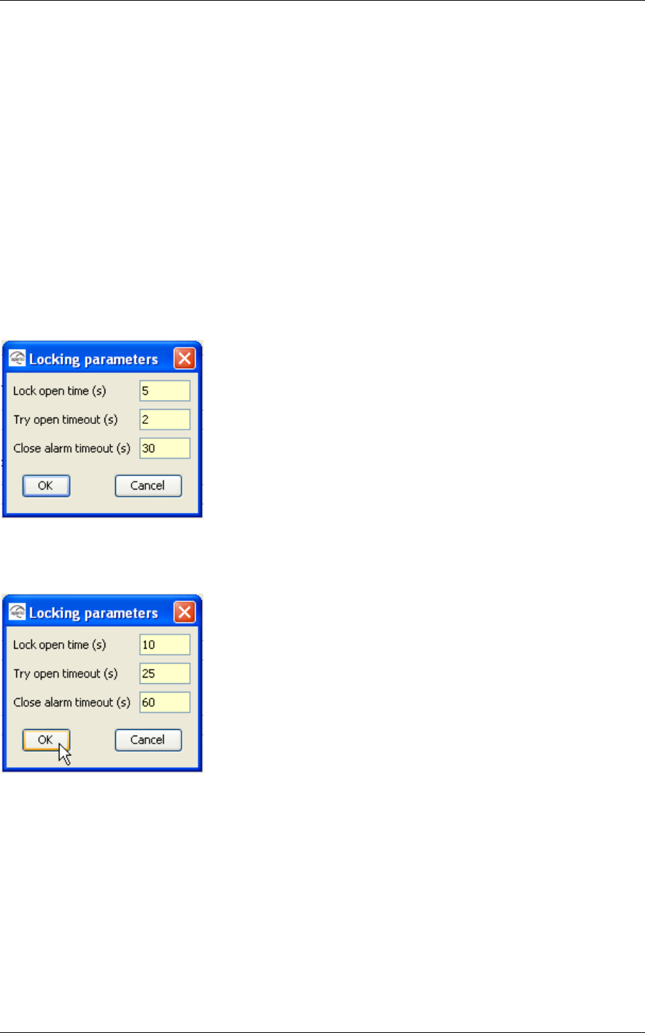
Reference Manual
Aperio Technology
86 (91)
8.4.3 Locking parameters
You can configure time for different operations in the lock.
These are:
How long the lock should be open in seconds.
How long the lock should try to open in seconds.
After how long time in seconds a close alarm should be generated and sent to
the event log.
Default values are 5 seconds for “Lock open time”, 2 seconds for “Try open
timeout” and 30 seconds for “Close alarm timeout”.
Follow these steps to configure the status messages in the configuration wizard:
1. Click Change
2. The default configuration is shown, if you want to keep it just click OK. If
you want to change to something else follow the next steps…
3. To change the times fill in valid values in seconds in the field for wanted
parameter.
Valid values are
for “Lock open time” - between 1 to 65 seconds
for “Try open time” – 1 to 15 seconds
for “Close alarm timeout” – 30 to 255 seconds
4. Confirm with OK
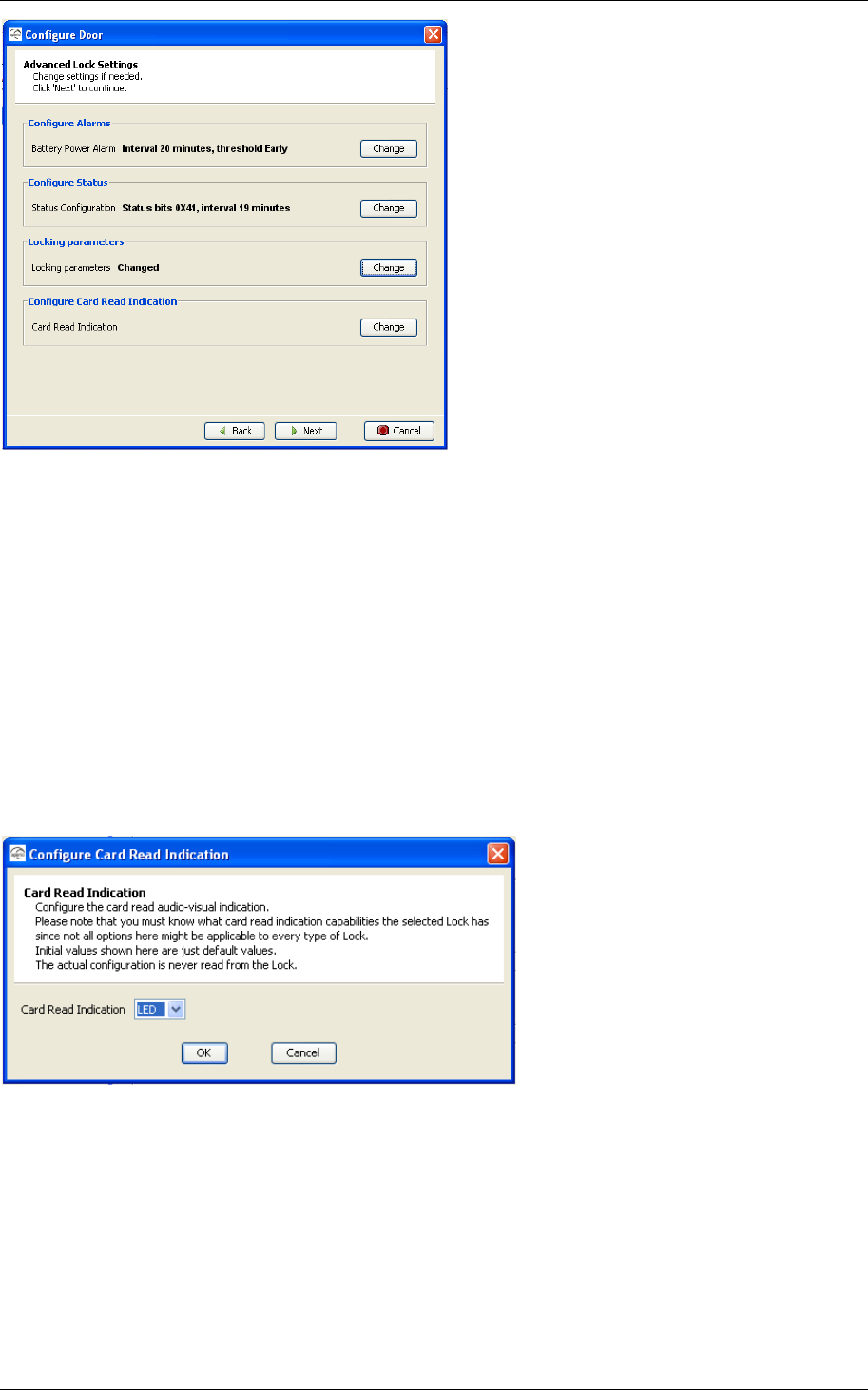
Reference Manual
Aperio Technology
87 (91)
You will see that one or more parameters have been changed in the configuration
wizard.
5. Click Next and continue through the configuration wizard… 5.6 Save the
configuration
8.4.4 Card Read Indication
Different locks can have different mechanism for audio-visual indication of
successful card reading. Here it is possible to disable card read indication or to
set it to LED. Future Aperio locks might have support for other mechanisms such
as buzzers.
1. Choose none to disable card read indication or choose LED to use yellow
LED blink to indicate successful card reading. See chapter 2.7 Lock normal
operation LED indication for more information on LED indication.
2. Click OK to confirm or Cancel to ignore any changes in Card Read
Indication.
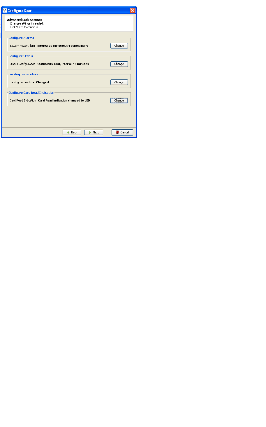
Reference Manual
Aperio Technology
88 (91)
The result of the card read indication configuration change is displayed in the
wizard panel, as shown above. Click next to continue to the next step in the
configuration wizard.

Reference Manual
Aperio Technology
89 (91)
Appendix A, Mifare RFID Configuration Online Help
Mifare RFID Configuration
UID Configuration
No parameters are needed when simple UID reading is configured.
Sector Configuration
If sector configuration is done wrong, the lock may become inoperable. Make
sure you know what you are doing before changing these values.
Sector
To configure the lock for sector card reading, you need to set from what sector
on the card you would like to read card credential data. Sectors range from 0 to
15 for Mifare 1K Classic cards and from 0 to 39 for Mifare 4K Classic cards.
Start Address
It is possible to use parts of blocks within a sector as credential data. The data
can even span multiple blocks. To configure this you need to set the start
address byte within the sector. You also need to supply the length in bytes for
the credential.
The start address can range from 0 to 47 when used with 1K Classic cards and
for 4K Classic cards for sectors 0 to 31. For sectors above 31 (only 4K Classic
cards), the start address can be within the range 0 - 239.
Data Length
The length of the credential data can be 1 - 48 (you are not allowed to set 0
length). Note that for sectors above 31 we can not use a credential larger than
48 bytes even though that we have more blocks available in these sectors.
Mifare Key
To be able to read the credential data a valid Mifare key must be supplied. The
key is 6 bytes long and is entered using hexadecimal values. For example:
A70E190AB34C
Key Type
The card has two keys, Key A and Key B. Depending on the access configuration
of the card, Key A or Key B is given the right to read from a sector. To be able to
authorize to a sector the lock needs to know if read access is given to Key A or
Key B.
Note: If key B is selected as sector data read key, make sure that the access
bits on the card prevent read of key B. If key B is readable on the card, key B
can not be used to read the card data.
All values are mandatory.
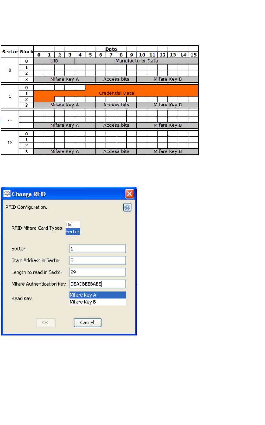
Reference Manual
Aperio Technology
90 (91)
Example
Below is an example where the card has the credential data in sector 1 starting
at byte 5 with length 29.
The card is configured to use Key A as the read key. Below is a screen shot from
the sector configuration dialog for the card in this example.

Reference Manual
Aperio Technology
91 (91)
Appendix B, Security Statement
The security of Aperio is according to the following:
o Authentication: 3-pass mutual authentication (challenge-response
protocol) based on AES128. Standard Aperio authentication scheme.
o Confidentiality in communication: The communication is encrypted
by a unique session key.
o Confidentiality of information in the lock: Secret information such as
encryption keys is never visible outside the protected flash of the
microcontroller.
o Unique encryption key seed for each installation.
o Encrypted database in Programming Application is password
protected. The computer must also be physically protected.
o AES and RNG tested according to (National Institute of Standards
and Technology) NIST test vectors.
http://csrc.nist.gov/groups/STM/cavp/documents/rng/RNGVS
.pdf
http://csrc.nist.gov/publications/fips/fips197/fips-197.pdf