Triton Network Systems 28-SNP-03 User Manual Installation Manual
Triton Network Systems, Inc. Installation Manual
UserManual.wiki
>
Triton Network Systems
>
28-SNP-03 User Manual
>
Installation Manual
Contents
1.
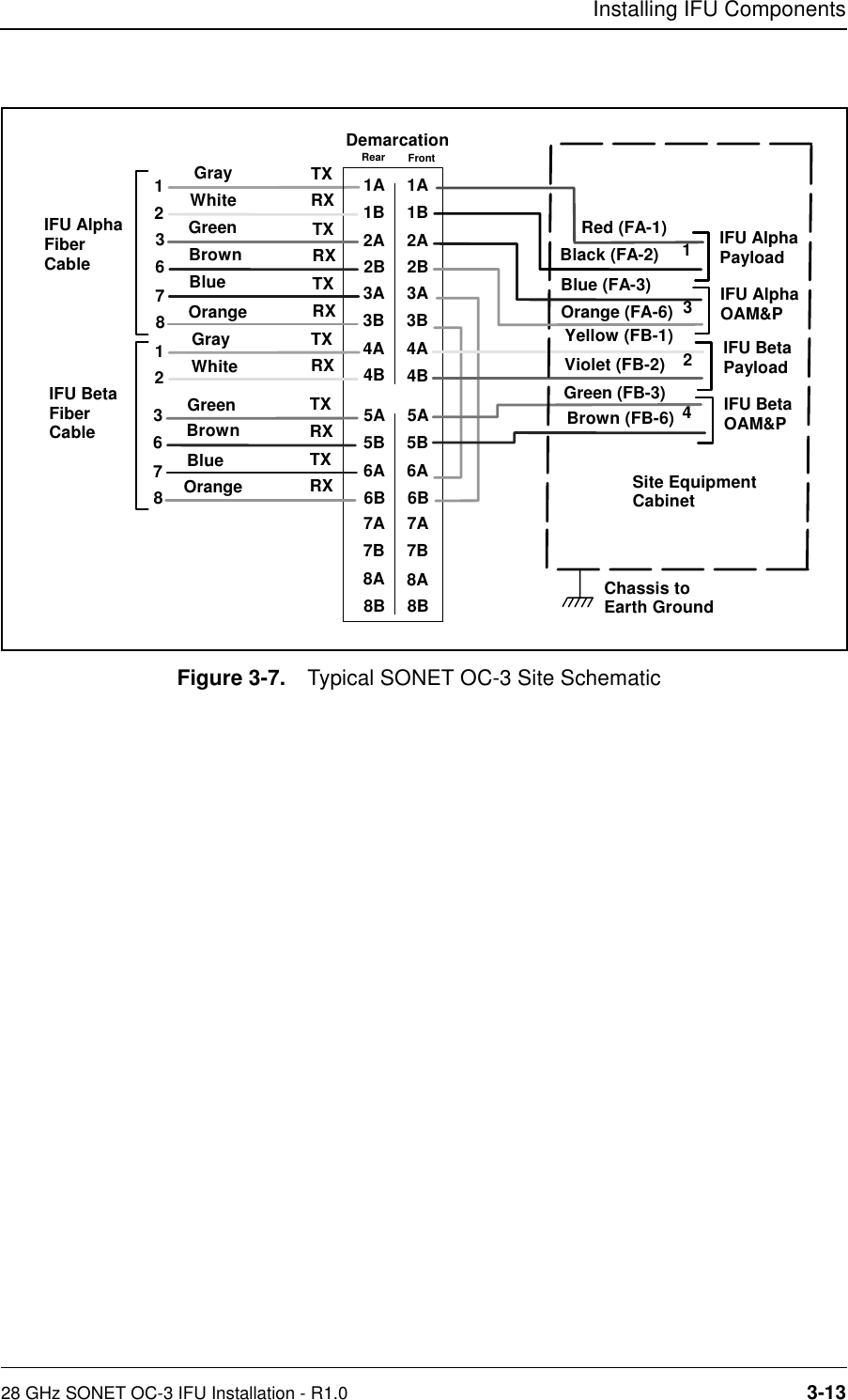
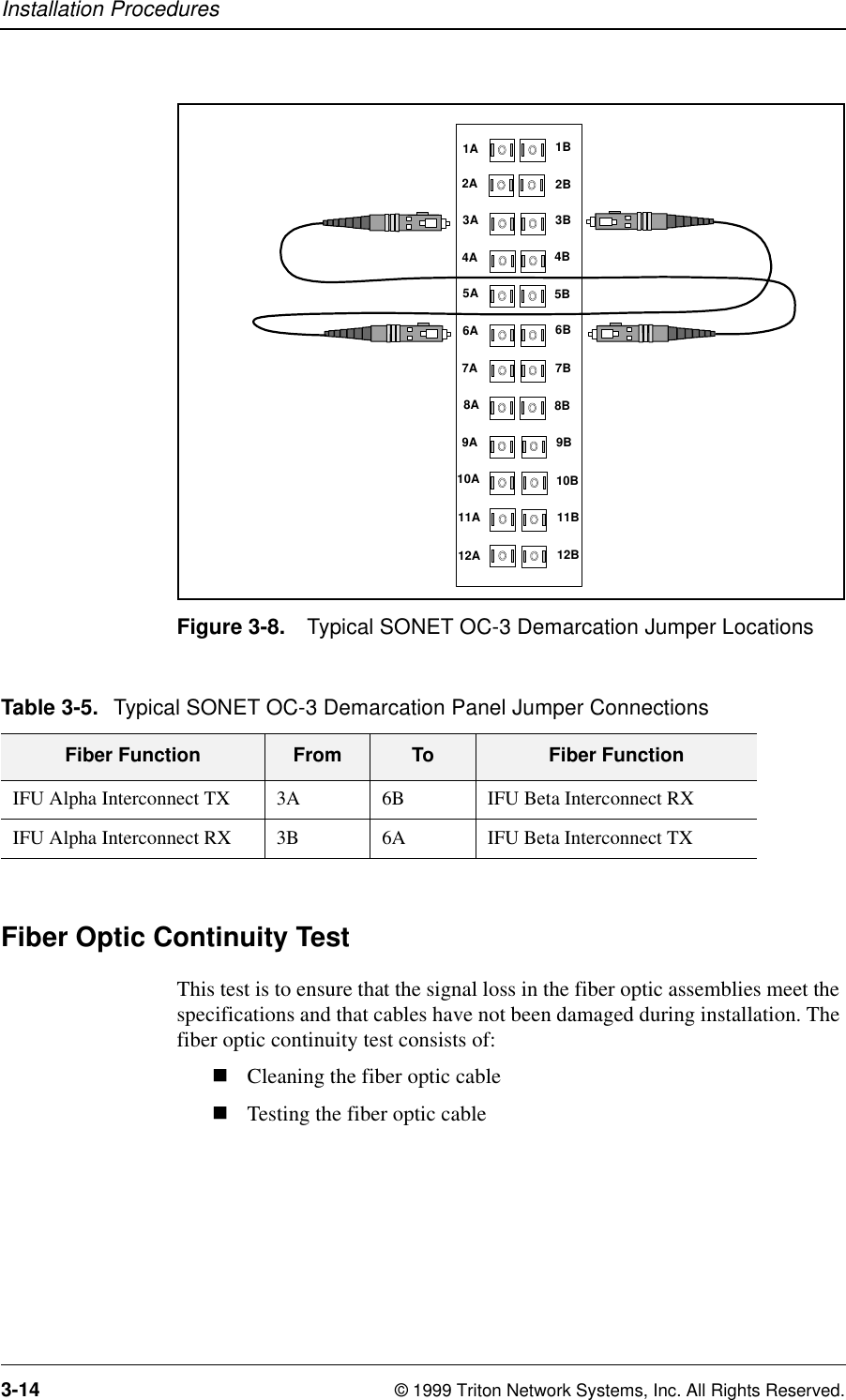
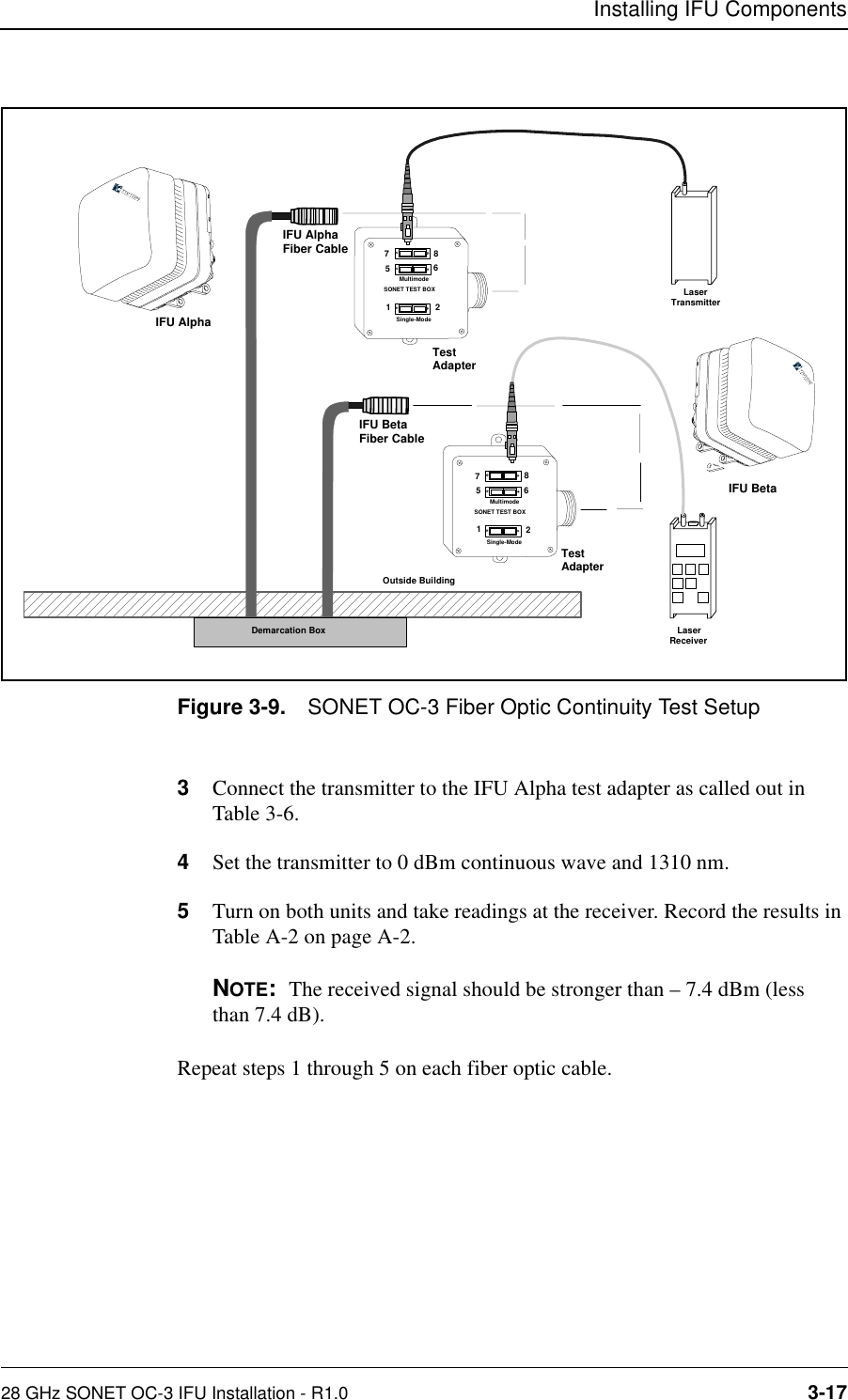
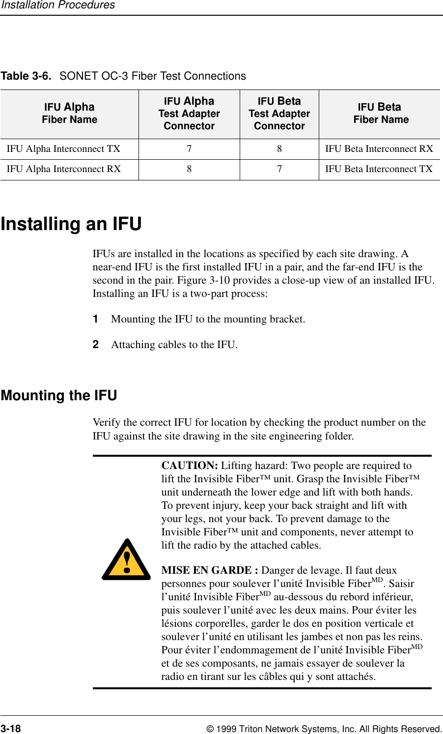
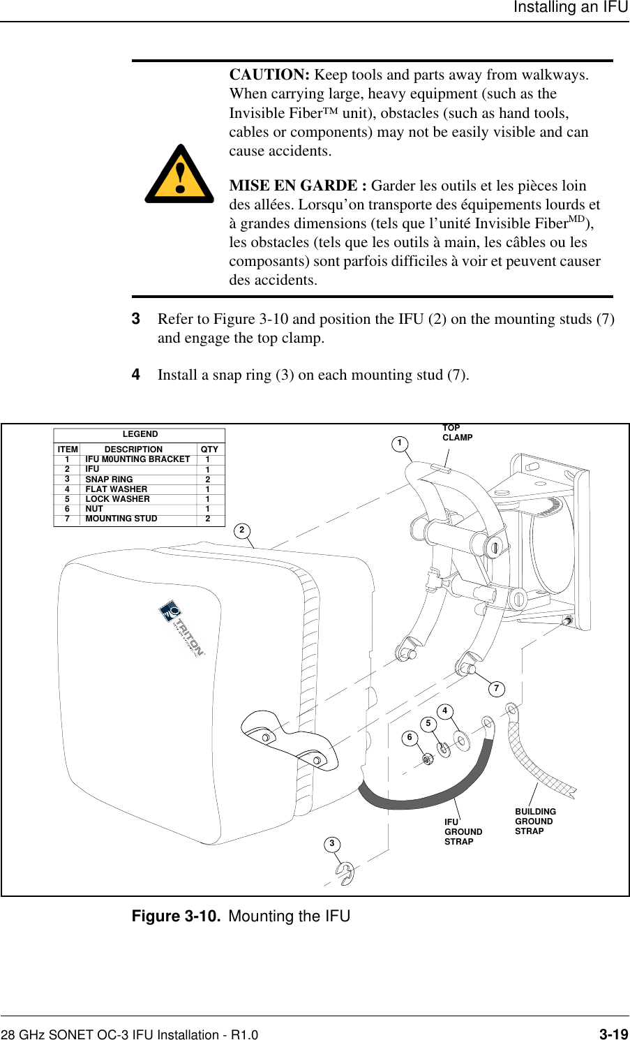
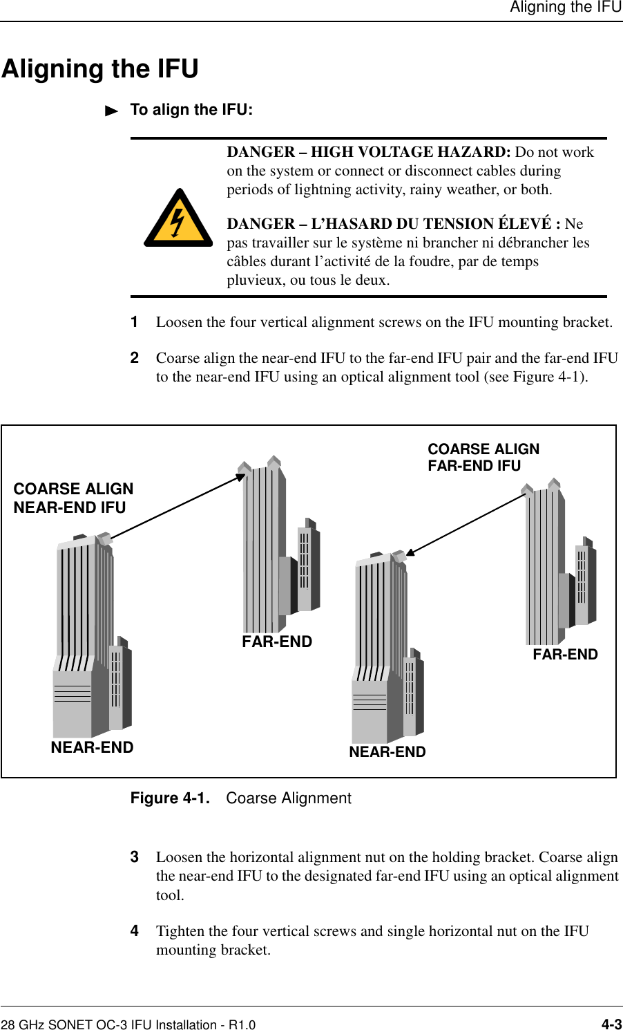
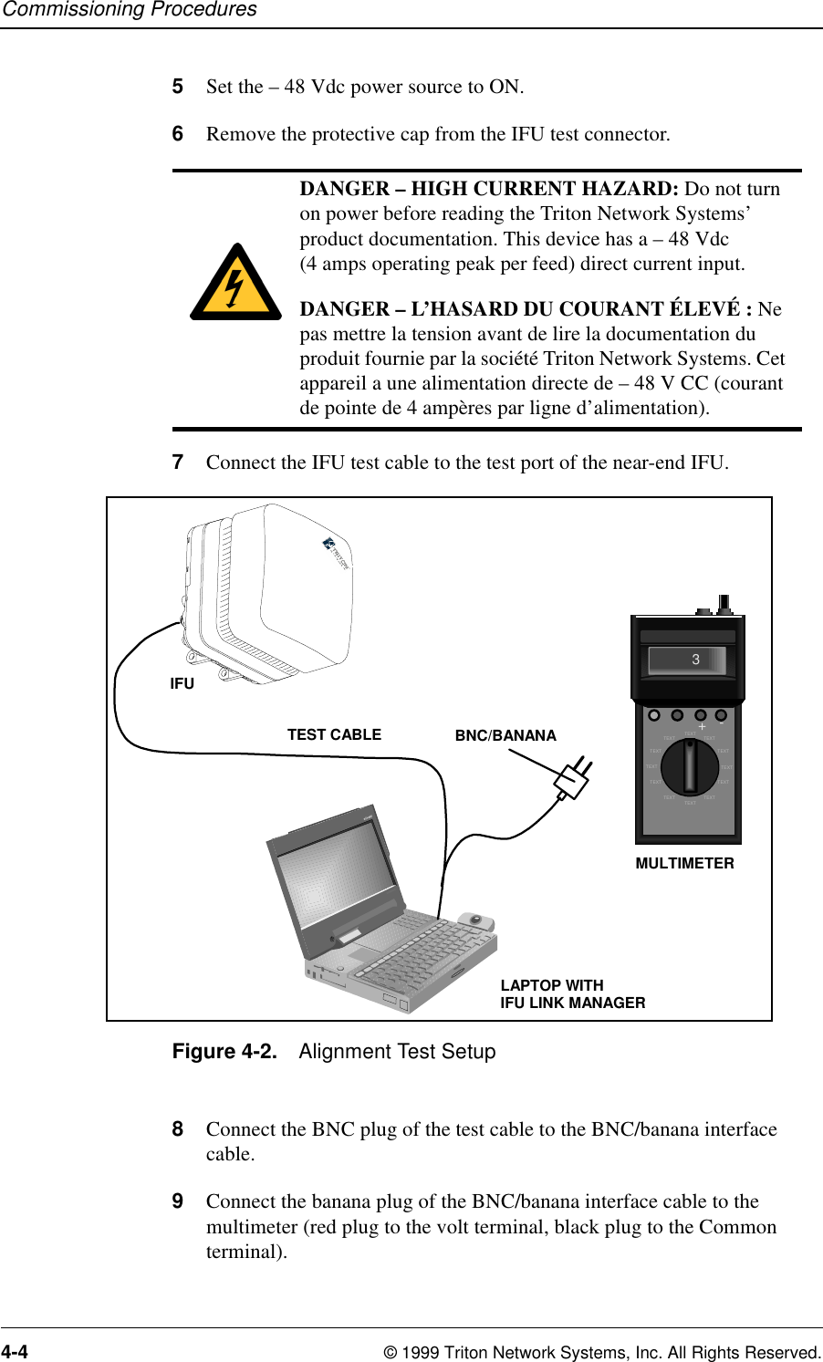
Installation Manual
2.
Operating Manual
Installation Manual
Navigation menu
Upload a User Manual
Namespaces
Wiki Guide
HTML
PDF
Info
Views
User Manual
Discussion / Help
Navigation
![,QYLVLEOH)LEHU708QLW,QVWDOODWLRQ*XLGHIRU*+]621(72&-$SSOLFDWLRQV](https://usermanual.wiki/Triton-Network-Systems/28-SNP-03.Installation-Manual/User-Guide-62138-Page-1.png)