Troybilt 12097 User Manual TILLER/EDGER Manuals And Guides L0403037
TROYBILT Front Tine, Gas Tiller Manual L0403037 TROYBILT Front Tine, Gas Tiller Owner's Manual, TROYBILT Front Tine, Gas Tiller installation guides
User Manual: Troybilt 12097 12097 TROYBILT TILLER/EDGER - Manuals and Guides View the owners manual for your TROYBILT TILLER/EDGER #12097. Home:Lawn & Garden Parts:Troybilt Parts:Troybilt TILLER/EDGER Manual
Open the PDF directly: View PDF ![]() .
.
Page Count: 20

0TRtII BILT
n m _w_
;T!
Before read this
Owner's manual
Model
12097
OWNER'SMANUAL
Tiller/Edger
•Safety
•Assembly
•Features and Controls
•Operation
•Maintenance
•Parts List
GARDEN WAY INCORPORATED
2
Dear Owner:
Congratulationson your purchaseof a Tiller/Edgerwith
EdgerAttachment. It has beendesigned, engineeredand
manufactured to give you the best possible dependabilityand
performance.
Pleasecarefully readthis Manual which provides information
on how to safely and easily set-up, operate and maintain your
machine. Besure thatyou and any other operators carefully
follow the recommended safety practices at all times. Failure
to do so could result in personal injury or property damage.
If you should ever have any problems or questions, please
contact your local authorized service dealer or call the Factory.
Seethe backcover of this Manual for Customer Serviceinfor-
mation.
We want to be sure that you arecompletely satisfied at all
times.
See Back Cover for
Customer Service Information
SafetyAlert Symbol
_ his is a safety alert symbol. It is used in this
manual and on the unit to alert you to potential haz-
ards. When you seethis symbol, readand obey the
messagethat follows it. Failureto obey safety mes-
sagescould result in personal injury or property damage.
This machine meets voluntary safety standard
B71.8 - 1996, which is sponsored by the Outdoor
Power Equipment Institute, Inc., and is published by
the American National Standards Institute.
WARNING
The engine exhaust from this product contains chemi-
cals known to the State of California to cause cancer,
birth defects or other reproductive harm.
Table of Contents
SECTION1: SAFETY........................................... 3
Training....................................................................... 3
Preparation................................................................. 3
Operation.................................................................... 4
Maintenance/Storage.................................................. 4
SECTION2: ASSEMBLY........................................ 5
Unpacking Instructions ............................................... 5
Assembly Steps.......................................................... 5
SECTION3: FEATURESANDCONTROLS..................... 7
SECTION4: OPERATION...................................... 8
Pre-start Preparation.................................................. 8
Stopping and Starting the Engine............................... 8
Tilling and Cultivating ................................................. 9
Using the EdgerAttachment ....................................... 10
Attachments ............................................................... 10
SECTION5: MAINTENANCE.................................. 11
EquipmentMaintenance ............................................. 11
EngineMaintenance ................................................... 11
Tine Removaland Installation..................................... 12
Storage....................................................................... 13
Troubleshooting.......................................................... 14
Safetyand Operating Decals....................................... 14
PARTSLIST ..................................................... 15
INDEX............................................................ 19
CUSTOMERSERVICEINFORMATION.............. BACKCOVER
TOAVOIDINJURY:
•READTHEOPERATOR'SMANUAL.
•KNOWLOCATIONANDFUNCTIONOFALL CONTROLS.
•KEEPALL SAFETYDEVICESAND SHIELDS IN PLACEAND
WORKING,
•NEVERALLOWCHILDRENOR UNINSTRUCTEDADULTSTO
OPERATEMACHINE.
•SHUT OFF ENGINEAND DISCONNECTSPARKPLUG WIRE
BEFORE MANUALLY UNCLOGGING TINES OR MAKING
REPAIRS,
•KEEPBYSTANDERSAWAYFROM MACHINE.
•KEEPAWAYFROM ROTATINGPARTS.
•USE EXTREMECAUTIONWHEN REVERSINGOR PULLING
THEMACHINETOWARDSYOU.
Safety
SPARKARRESTERWARNINGTO RESIDENTSOF CALIFORNIAAND SEVERALOTHERSTATES
Under California law, and under the laws of severalother states, you are not permitted to operate an internal combustion engine
using hydrocarbon fuels on any forest, brush, hay,grain, or grass covered land; or land covered by any flammable agricultural crop
without an enginespark arrester in continuous effective working order.
The engineon the unit is an internal combustion enginewhich burns gasoline, a hydrocarbon fuel, and must be equippedwith a
spark arrester muffler in continuous effective working order. The spark arrester must be attachedto the engine exhaust system in
such a manner that flames or heatfrom the system will not ignite flammable material. Failureof the owner/operator of the unit to
comply with this regulation is a misdemeanor under California law (and other states) and may also bea violation of other state
and/or federal regulations, laws, ordinances or codes. Contactyour local fire marshal or forest service for specific information
about which regulations apply in your area.
TRAINING
• Readthis Owner's Manual and the sep-
arate EngineOwner's Manual very care-
fully before operating this equipment. Be
completely familiar with the controls and
the proper use of the equipment. Know
how to stop the unit and disengagethe
controls quickly. A replacement Manual
is availableby contacting your authorized
dealeror the Factory.
• Neverallow children or untrained
adults to usethis equipment. Let adults
operate the unit only if instructed
properly.
• Keepthe areaof operation clear of all
persons, particularly small children and
pets. Keepbystanders at least 25 feet
from the areaof operation.
• Keepin mind that the operator or user
is responsible for accidents or hazards
occurring to other people,their property
andthemselves.
• Familiarizeyourself with all of the
safety and operating decals on this equip-
ment and on any of its attachments or
accessories.
• Do not run engine in an enclosedarea.
Engineexhaust contains carbon
monoxide gas, a deadly poison that is
odorless, colorless, and tasteless. Do not
operate this equipment near buildings,
windows, or air conditioning equipment.
• Do not allow hands or any other part of
the body or clothing nearthe rotating
tines or near any other moving part. The
tines begin to rotate forward once the
engine is started and the Throttle/Tines
Lever is squeezed. The tines continue to
rotate until the operator releasesthe
Throttle/Tines Lever.
• Before inspecting or servicing any part
of the equipment, shut off engine, make
sure all moving parts havecome to a
complete stop, then disconnect spark
plug wire from spark plug and move wire
awayfrom the plug.
• Do not operate this equipment if you are
underthe influenceof alcohol, medication,
or when you aretired or ill.
PREPARATION
• Thoroughly inspect the areawhere the
equipment is to be used and remove all
foreign objects.
• Make sure that the Throttle/Tines Lever
is releasedand is in the neutral position
before you begin to start the engine.
• Donot operatethe machinewithout
wearing adequateouter garments. Avoid
loose garments orjewelry that could get
caught in moving parts of the machine or
its engine.
• Do not operate the equipment when
barefoot or when wearing sandals,
sneakers,or similar lightweight footwear.
Wear protective footwear that will protect
your feet and improve footing on all
surfaces.
• Wear approved safety glasses when op-
erating this equipment. The operation of
any powered machinecan result in for-
eign objects being thrown by high-speed
rotating parts.
• Do not till near underground electric
cables,telephone lines, pipes, or hoses.
If in doubt, contact your utility or tele-
phone company to locate underground
services.
• Handlefuel with care. It is highly
flammable and has explosive vapors.
Takethese precautions:
a. Usean approved fuel container.
b. Addfuel before starting the engine.
Neverremovethe cap of the fuel tank
or add fuel while the engine is running
or when the engine is hot. Operators
shall not smoke.
c. Keepmatches, cigarettes, cigars,
pipes, open flames, and sparks away
from the fuel tank and fuel container.
d. Fill fuel tank outdoors and with ex-
treme caution. Neverfill fuel tank
when indoors. Usea funnel or spout
to prevent spillage.
e. Replaceall fuel tank and fuel container
capssecurely.
f. If fuel is spilled, do not attempt to start
the engine, but movethe machineaway
from the area of spillage and avoid cre-
ating any source of ignition until fuel
vapors havedissipated.
• Nevermake adjustments to your equip-
ment when the engine is running or spark
plug wire is connected (unless specifically
recommended in Owner's Manual).
OPERATION
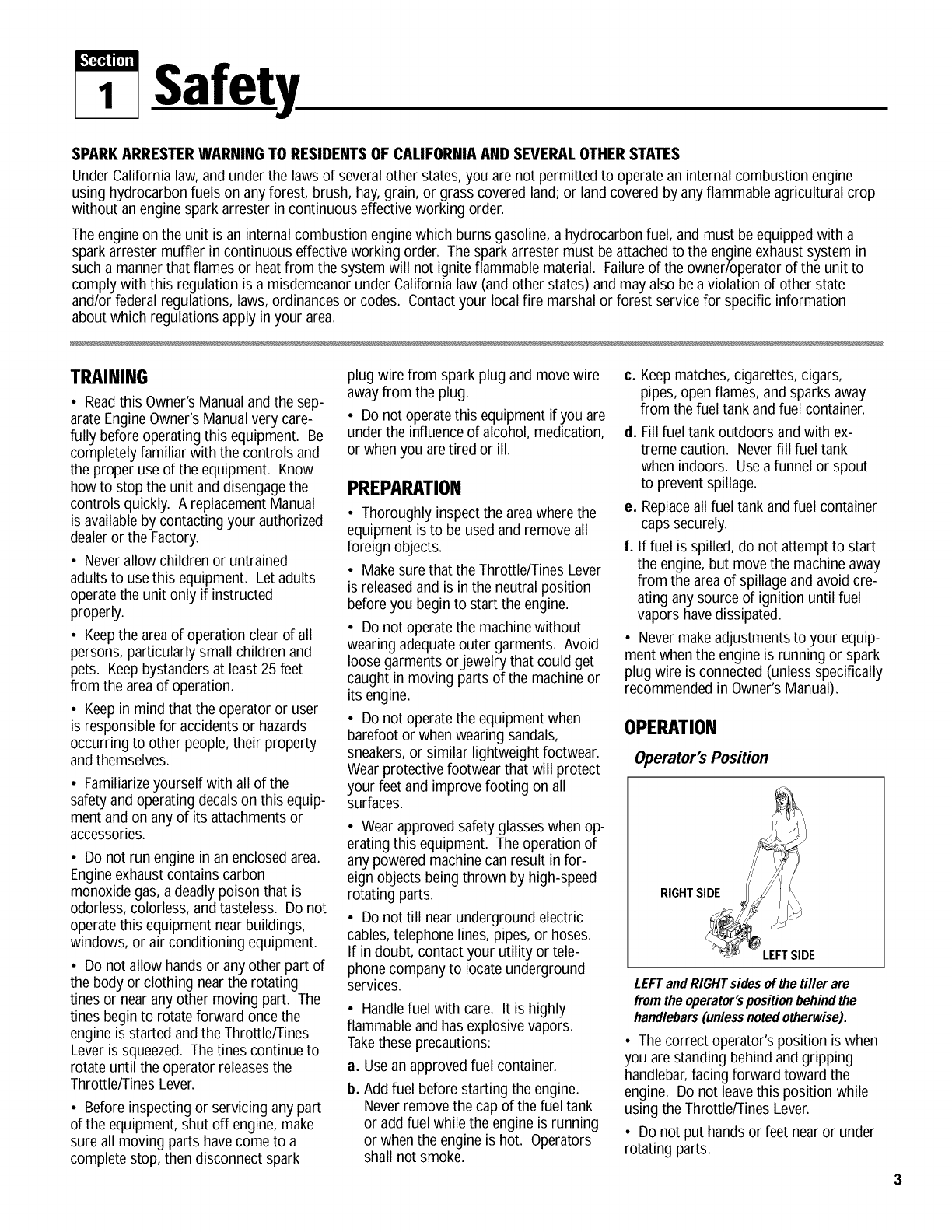
Operator's Position
LEFTand RIGHTsides of the tiller are
from the operator'spositionbehindthe
handlebars(unlessnotedotherwise).
• The correct operator's position is when
you arestanding behind and gripping
handlebar,facing forward toward the
engine. Do not leavethis position while
using the Throttle/Tines Lever.
• Do not put hands or feet nearor under
rotating parts.
Section1: Safety
•Exerciseextreme caution when on or
crossing gravel drives, walks or roads.
Stay alert for hidden hazardsor traffic.
Do not carry passengers.
•After striking a foreign object, stop the
engine, let all moving parts come to a
complete stop, disconnectthe spark plug
wire and prevent it from touching the
spark plug, then carefully inspect the ma-
chine for damage. Repairthe damage
before restarting andoperating the
machine.
• Exercisecaution to avoid slipping or
falling.
• If the machine should start to vibrate
abnormally, stop the engine. Disconnect
the spark plug wire and prevent it from
touching the plug. Check immediately for
the cause. Vibration is generally a
warning of trouble. Fixthe problem
before using the equipment again.
• Stop the engine, disconnect the spark
plug wire and prevent it from touching the
spark plug wheneveryou leavethe equip-
ment, before unclogging the tines, or
when making any repairs, adjustments or
inspections.
• Takeall possible precautions when
leaving the machine unattended. Always
stop the engine. Disconnect the spark
plug wire and prevent it from touching the
plug.
• Before cleaning, repairing, or in-
specting, stop the engineand make cer-
tain all moving parts havestopped. Dis-
connect the spark plug wire and prevent it
from touching the spark plug to avoid ac-
cidental starting.
• Neveroperate equipment without
proper guards, plates, or other protective
safety devices in place.
• Do not run the engine in an enclosed
area. The exhaust fumes from the engine
contain extremely dangerous carbon
monoxide gas. This gas is colorless,
odorless, tasteless and deadly poisonous.
• Keepchildren and pets away.
• Beawarethat the equipment may unex-
pectedly bounce upward orjump forward
if the tines should strike extremely hard
packedsoil, frozen ground, or buried ob-
staclessuch as largestones, roots or
stumps. If you are in doubt about the
tilling conditions, always use the fol-
lowing operating precautions to assist
you in maintaining control of the
equipment:
a. Stand behind the equipment, using
both hands on the handlebars. Relax
your arms, but use a securehand
grip.
b. Start tilling at shallow depths, working
gradually deeper with each pass.
c. Clearthe tilling areaof all largestones,
roots, and other debris.
d. In an emergency,stop the tines by re-
leasing the Throttle/Tines Lever on the
handlebar. To stop the engine, move
the engineOn/Off switch to OFE
• Donot overloadthe machine's capacity
by attempting to till too deeply at too fast
a rate.
• Neveroperate the equipment on slip-
pery surfaces. Look behind and use care
when backing up.
• Do not operate the equipment on a
slope that is too steep for safety. When
on slopes, slow down and makesure you
have good footing.
• Neverallow bystandersnear the unit.
• Only use attachmentsand accessories
that are factory-approved.
• Neveroperate the equipment without
good visibility or good light.
• Neveroperate the unit if you aretired,
or under the influence of alcohol, drugs,
or medication.
• Donot tamper with the engine gov-
ernor settings on the machine; the gov-
ernor controls the maximum safeoper-
ating speedand protects the engine and
all other moving parts from damage
causedby engine overspeed. Authorized
service shall be sought if a problem
exists.
• Do not touch engineparts which may
be hot from operation. Allow parts to
cool before inspecting, cleaning or
repairing.
• Remember:you can stop the tines by
releasingthe Throttle/Tines Lever. Move
the engine On/Off switch to OFFto shut
the engine off.
• Nevertransport this machinewhen the
engine is running.
• Terminals and non-insulated electrical
parts shall be protected against shorting
during normal servicing, refueling or
lubrication.
• Useextreme caution when reversing or
pulling the machinetoward you.
• Start the engine carefully according to
instructions and with feet well awayfrom
the tines.
MAINTENANCE/STORAGE
• Keepthe tiller, attachments and acces-
sories in safeworking condition.
• Checkall nuts, bolts, and screws at fre-
quent intervals for proper tightness to be
sure equipment is in safeworking
condition.
• Neverstore equipment with fuel infuel
tank inside a building where fumes may
reach an open flame or spark (hot water
and spaceheaters, furnaces, clothes
dryers, stoves, electric motors, etc.).
• Allow the engineto cool before storing
the equipment.
• Keep the engine free of grass, leaves,
or greaseto reducethe chance of afire
hazard.
• Store gasoline in a cool, well-ventilated
area,safely awayfrom any spark- or
flame-producing equipment. Store gaso-
line in an approved container, safely away
from the reach of children.
• Neverperform maintenancewhen
engine is running or spark plug wire is
connected unless instructed to do so.
• If fuel tank must be drained,do so
outdoors.
• Follow manufacturer's recommenda-
tions for safe loading, unloading, trans-
port and storage of machine.
4
!,'£4"4U;_
2Assembly
To prevent personal injury or property
damage, donot startthe engineuntil all
assembly steps are complete and you
have read andunderstandthe safetyand
operatinginstructionsin this manual.
INTRODUCTION
Readthese instructions in their entirety
before you attempt to assemble or op-
erateyour new equipment.
The Border/EdgerAttachment (H, Figure
5) does not needto be installed until you
are readyto do edging projects (refer to
instructions in this Section).
IMPORTANT:Thecorrect mixture of un-
leadedautomotive gasoline and two-cycle
motor oil (a 24:1 ratio of gasoline to two-
cycle oil) must be addedto the fuel tank
before starting the engine. Seeinstruc-
tions in this Section.
UNPACKINGINSTRUCTIONS
1. Inspect your machine immediately. If
you find or suspect damageto the carton
or contents, contact your local authorized
dealeror the Factoryfor assistance.
2. Removeany packing material. Check
for small parts before discarding the
packing material. Loose parts include the
following:
(1) Wheel (for edging)
(1) EdgerTine
(2) *Long Bushings
(1) *Short Bushing
* Packedin a separateplastic bag.
3. Perform the assembly on a clean, level
surface. Becareful not to severely bend
any of the control cables on the unit.
4. Beforestartingany assemblysteps,
disconnectthe engine sparkplugwire
from the spark plug.
ASSEMBLYSTEPS
STEP 1: Unfold and
Adjust Handlebars
IMPORTANT: Becareful not to pinch any
wires or cables while unfolding and ad-
justing the handlebars.
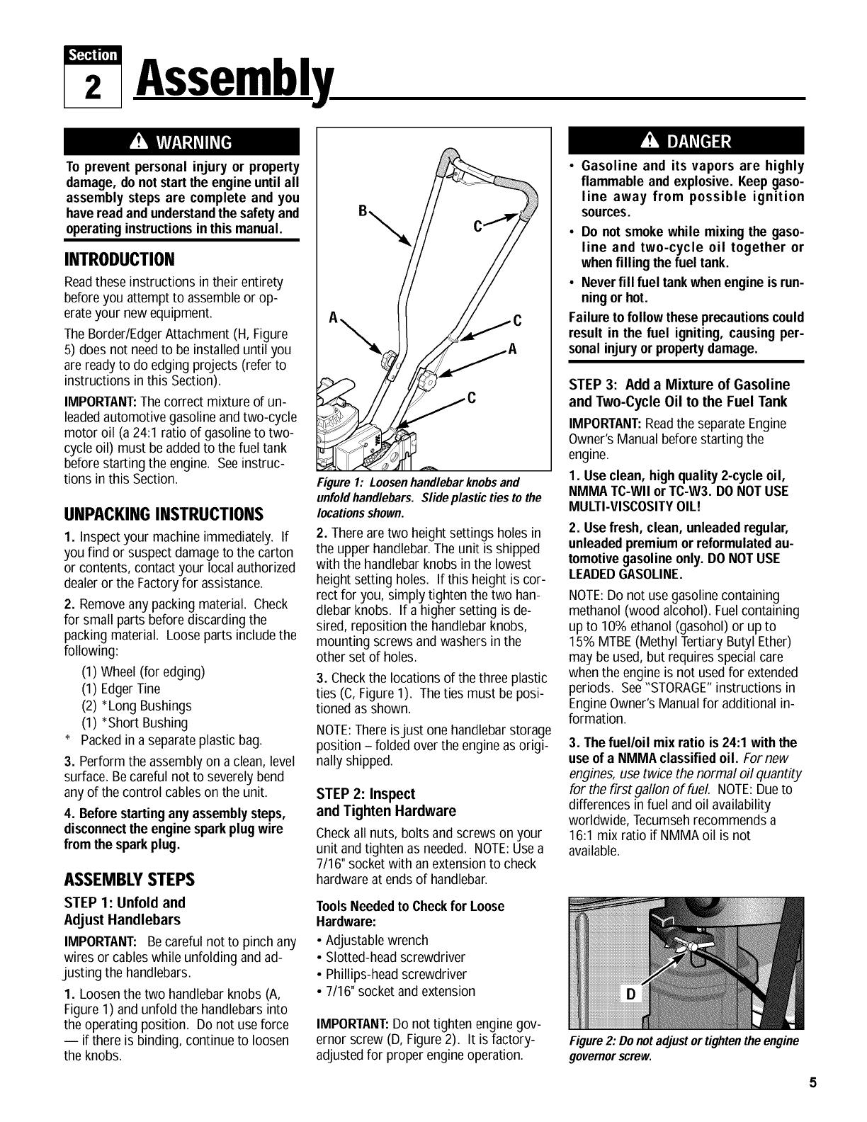
1. Loosen the two handlebarknobs (A,
Figure 1) and unfold the handlebars into
the operating position. Do not useforce
-- if there is binding, continue to loosen
the knobs.
[
"\
Figure 1: Loosenhandlebarknobsand
unfoldhandlebars. Slideplastic ties to the
locationsshown.
2. Thereare two height settings holes in
the upper handlebar.The unit is shipped
with the handlebarknobs in the lowest
height setting holes. If this height is cor-
rect for you, simply tighten the two han-
dlebar knobs. If a higher setting is de-
sired, reposition the handlebarknobs,
mounting screws and washers in the
other set of holes.
3. Checkthe locations of the three plastic
ties (C,Figure 1). Theties must be posi-
tioned as shown.
1
NOTE:There isjust one handlebarstorage
position - folded over the engineas origi-
nally shipped.
STEP 2: Inspect
and Tighten Hardware
Checkall nuts, bolts and screws on your
unit and tighten as needed. NOTE:Usea
7/16" socket with an extension to check
hardware at ends of handlebar.
ToolsNeeded to Checkfor Loose
Hardware:
• AdJustablewrench
• Slotted-headscrewdriver
• Phillips-head screwdriver
• 7/16"socket and extension
IMPORTANT:Do not tighten engine gov-
ernor screw (D, Figure 2). It is factory-
adjustedfor proper engineoperation.
•Gasoline and its vapors are highly
flammable and explosive. Keepgaso-
line away from possible ignition
sources.
•Do not smoke while mixing the gaso-
line and two-cycle oil together or
whenfilling the fuel tank.
• Never fill fuel tankwhenengine is run-
ningor hot.
Failure to follow these precautionscould
result in the fuel igniting, causing per-
sonal injuryor propertydamage.
STEP 3: Add a Mixture of Gasoline
and Two-Cycle Oil to the Fuel Tank
IMPORTANT:Readthe separateEngine
Owner'sManual beforestarting the
engine.
1. Use clean, highquality2-cycle oil,
NMMA TC-WII orTC-W3. DO NOTUSE
MULTI-VISCOSITYOIL!
2. Usefresh, clean, unleadedregular,
unleadedpremiumor reformulatedau-
tomotivegasolineonly. DO NOTUSE
LEADEDGASOLINE.
NOTE:Do not use gasoline containing
methanol (wood alcohol). Fuel containing
up to 10% ethanol (gasohol) or up to
15% MTBE(Methyl Tertiary Butyl Ether)
may be used, but requires specialcare
when the engine is not used for extended
periods. See"STORAGE"instructions in
EngineOwner's Manual for additional in-
formation.
3. The fuel/oil mix ratio is 24:1 with the
use of a NMMA classifiedoil. For new
engines, use twice the normal oil quantity
for the first gallon of fuel. NOTE:Dueto
differences in fuel and oil availability
worldwide, Tecumsehrecommends a
16:1 mix ratio if NMMA oil is not
available.
Figure2: Do not adjust or tightenthe engine
governorscrew.
Section2: Assembly
Chart 1: FUEL MIXTURE
(Mixture Ratio is 24 parts gasoline to
1 part two-cycle oil)
U.S. Gas U.S. Oil
1 Gal. 5 oz.
2 Gal. 11 oz.
Metric Petrol Metric Oil
4 liters 167 ml
8 liters 333 ml
4. Donot mix fuel directly inenginefuel
tank. Always use a clean, safety-ap-
proved fuel container.
•ToMix:
A. Fill a clean,approved container one
quarter full with recommended
gasoline.
B. Add recommended amount of oil per
Chart 1: FUELMIXTURE.
C.Screw cap on container and shake
vigorously. Then unscrew cap and
fill container with gasoline per
Chart 1: FUELMIXTURE. Screw on
cap and shakeagain. Once mixed,
oil and gasoline will not separate.
Fill Fuel Tank:
1. Enginemustbe cool. Cleanarea
around fuel tank cap and removecap.
Inserta clean funnel intothe fuel tank.
2. Slowly pour gasoline/oil mixture into
fuel tank. Fill tank no higher than 1/2"
from top of tank to allow for gasoline ex-
pansion. Install fuel cap and clean up any
fuel spills.
Contact with rotating tines or other
moving parts can cause serious per-
sonal injury.
Before installing or removing attach-
ments,or adjustingor servicingthe ma-
chine, stop the engine, let all moving
parts come to a complete stop, discon-
nect the spark plug wire and move the
wire away fromthe sparkplug.
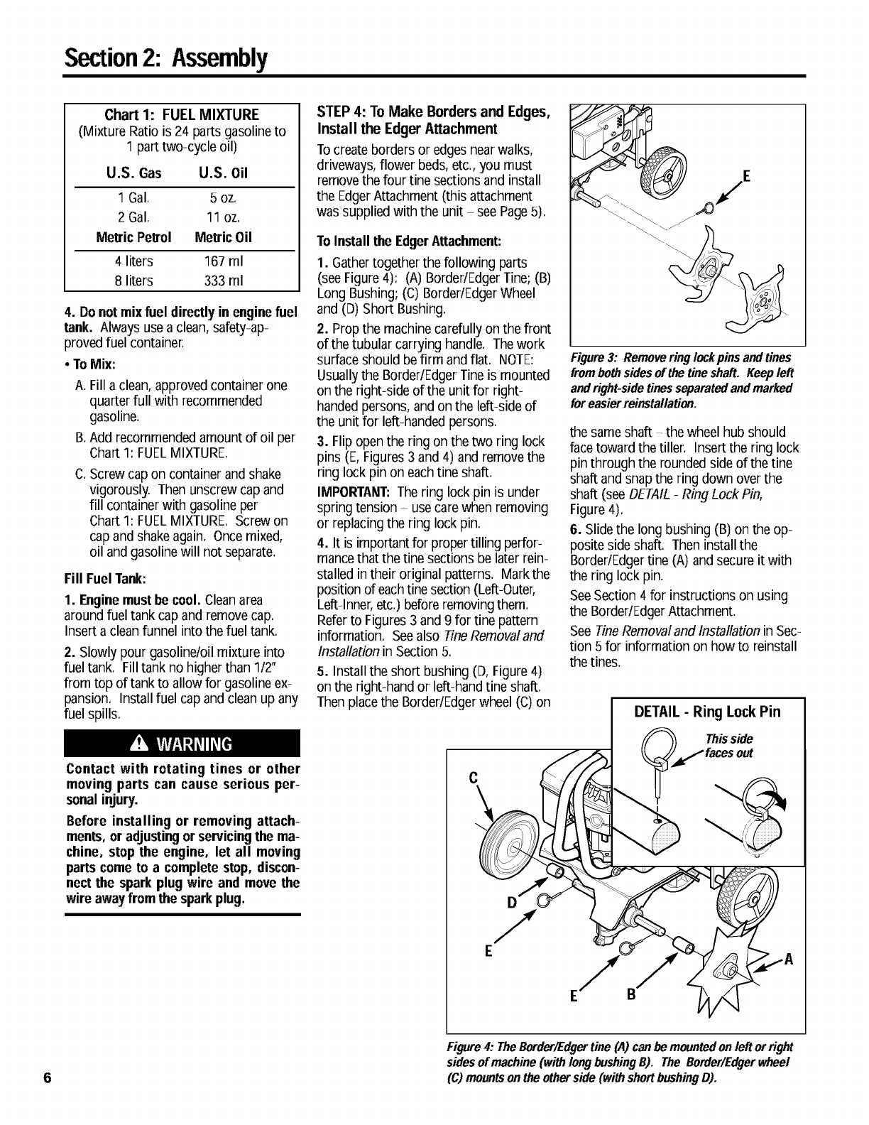
STEP 4: To Make Borders and Edges,
Install the Edger Attachment
Tocreate borders or edges nearwalks,
driveways, flower beds, etc., you must
removethe four tine sections and install
the EdgerAttachment (this attachment
was supplied with the unit - see Page5).
To Installthe EdgerAttachment:
1. Gathertogether the following parts
(see Figure 4): (A) Border/EdgerTine; (B)
Long Bushing; (C) Border/EdgerWheel
and (D) Short Bushing.
2. Prop the machine carefully on the front
of the tubular carrying handle. Thework
surface should befirm and flat. NOTE:
Usually the Border/Edger Tine is mounted
on the right-side of the unit for right-
handedpersons, and on the left-side of
the unit for left-handed persons.
3. Flip open the ring on the two ring lock
pins (E, Figures3 and 4) and remove the
ring lock pin on eachtine shaft.
IMPORTANT:Thering lock pin is under
spring tension -use carewhen removing
or replacing the ring lockpin.
4. It is importantfor proper tilling perfor-
mancethat the tine sections be laterrein-
stalled intheir original patterns. Markthe
position of eachtine section (Left-Outer,
Left-inner, etc.) before removingthem.
Referto Figures3 and 9 for tine pattern
information.Seealso TineRemovaland
InstallationinSection 5.
5. Install the short bushing (D, Figure4)
onthe right-hand or left-hand tine shaft.
Then place the Border/Edgerwheel (C) on
E
Figure 3: Removering lockpins and tines
frombothsides of the tineshaft. Keep left
and right-side tines separated andmarked
for easier reinstallation.
the same shaft -the wheel hub should
facetoward the tiller. Insert the ring lock
pin through the rounded side of the tine
shaft and snap the ring down over the
shaft (see DETAIL-Ring Lock Pin,
Figure 4).
6. Slidethe long bushing (B) on the op-
posite side shaft. Then install the
Border/Edgertine (A) and secure it with
the ring lock pin.
SeeSection 4 for instructions on using
the Border/EdgerAttachment.
See TineRemoval and Installation in Sec-
tion 5 for information on how to reinstall
the tines.
DETAIL -Ring Lock Pin
Thisside
Figure 4: TheBerder/Edgertine (A)can he mountedon left orright
sides of machine (with long bushingB). The Border/Edgerwheel
(C) mountson the otherside (with shortbushingD).
3Featuresand Controls
KNOWYOUREQUIPMENT
READ THIS OWNER'S MANUAL AND ALL SAFETY RULES BEFORE OPERATING YOUR EQUIPMENT.
location and function of all features and controls on the equipment. Save this manual for future reference.
Know the
Beforeoperating your machine, carefully read and under-
standall safety, controls,and operatinginstructionsinthis
Manual, the separate Engine Owner's Manual and on the
decalson the machine,
Failure to follow these instructionscan result in serious
personal injury,
G
J
D
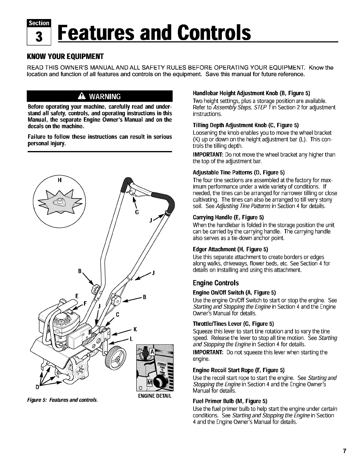
Figure5: Featuresandcontrols. ENGINEDETAIL
HandlebarHeightAdjustment Knob(B, Figure 5)
Twoheight settings, plus a storage position are available.
Referto Assembly Steps, STEP 1in Section 2 for adjustment
instructions.
Tilling DepthAdjustmentKnob(C, Figure 5)
Loosening the knob enablesyou to move the wheel bracket
(K) up or down on the height adjustment bar (L). Thiscon-
trols the tilling depth.
IMPORTANT:Do not movethe wheel bracket any higher than
the top of the adjustment bar.
AdjustableTine Patterns(D, Figure5)
Thefour tJnesections areassembled at the factory for max-
imum performance under a wide variety of conditions. If
needed,the tines can bearranged for narrower tilling or close
cultivating. Thetines can also be arrangedto till very stony
soil. SeeAdjusting TinePatterns in Section 4 for details.
CarryingHandle(E, Figure5)
When the handlebar is folded in the storage position the unit
can be carried by the carrying handle. Thecarrying handle
also serves as a tie-down anchor point.
EdgerAttachment (H, Figure5)
Usethis separateattachment to createborders or edges
along walks, driveways, flower beds,etc. SeeSection 4 for
details on installing and using this attachment.
Engine Controls
EngineOn/OffSwitch(A, Figure5)
Usethe engineOn/Off Switch to start or stop the engine. See
Starting and Stopping the Enginein Section 4 and the Engine
Owner's Manual for details.
Throttle/TinesLever(G, Figure 5)
Squeezethis leverto start tJnerotation and to vary the tJne
speed. Releasethe leverto stop all tine motion. See Starting
and Stopping the Enginein Section 4 for details.
IMPORTANT: Do not squeezethis leverwhen starting the
engine.
EngineRecoil Start Rope(F, Figure 5)
Usethe recoil start ropeto start the engine. See Startingand
Stopping the Enginein Section 4 and the EngineOwner's
Manual for details.
Fuel Primer Bulb(M, Figure 5)
Usethe fuel primer bulb to help start the engine under certain
conditions. See Starting and Stopping the Enginein Section
4 and the EngineOwner's Manual for details.
i,_[5€[!17_
4Operation
Before operatingthe unit carefully read
and understandall safety, control and
operating instructions in this Manual,
the separate Engine Owner's Manual
andthe decals onthe machine,
Failure to follow these instructionscan
result in seriouspersonal injury,
PRE-STARTPREPARATION
Before starting the engine, perform the
following checks and services:
1. Disconnect the spark plug wire from
the spark plug.
2. Movethe engineOn/Off switch to the
OFFposition.
3, Checkthe three plastic cable ties (J,
Figure 5). Besure that cables andties are
positioned as shown. Do not kink or
pinch the control cables in the handlebar.
4. AdJusthandlebar height to desired po-
sition (see Assembly Steps, STEP 1: in
Section 2).
5. Checkhardware for tightness.
GASOLINEIS HIGHLYFLAMMABLEAND
ITSVAPORSAREEXPLOSIVE.
Follow the gasoline safety rules in this
Manual (Section 1) and in the separate
EngineOwner'sManual,
Failure to follow gasolinesafety instruc-
tions can result in serious personal
injuryand propertydamage,
6. Add the correct fuel mixture (see As-
sembly Steps, STEP3: in Section 2).
7. Adjust the tilling depth as follows:
A
O
Figure6
a,
b.
Loosentilling depth adjustment
knob (A, Figure 6).
Move wheel bracket (B, Figure 6)
up in relation to the height ad-
justment bar (C). Moving the
bracket upward results in shal-
lower tilling, which is recom-
mended for initial use.
C,
IMPORTANT:Do not movethe
wheel bracket any higher than the
top of the adjustment bar.
Retightenthe depth adjustment
knob.
8. Reconnectthe spark plug wire.
STOPPINGAND
STARTINGTHE ENGINE
Stopping the Engine
Tostop the engine, move the engine
On/Off Switch (A, Figure 5) to the OFF
position.
Starting the Engine
Do not squeeze the Throttle/TinesLever
while startingengine.
Tines maypropel the machineforward if
the engine speed is advancedfrom idle.
Failure to complycan result in personal
injury or propertydamage.
1, Move engineOn/Off Switch to ON.
2, Determinewhich of the nextthree
starting conditions to use:
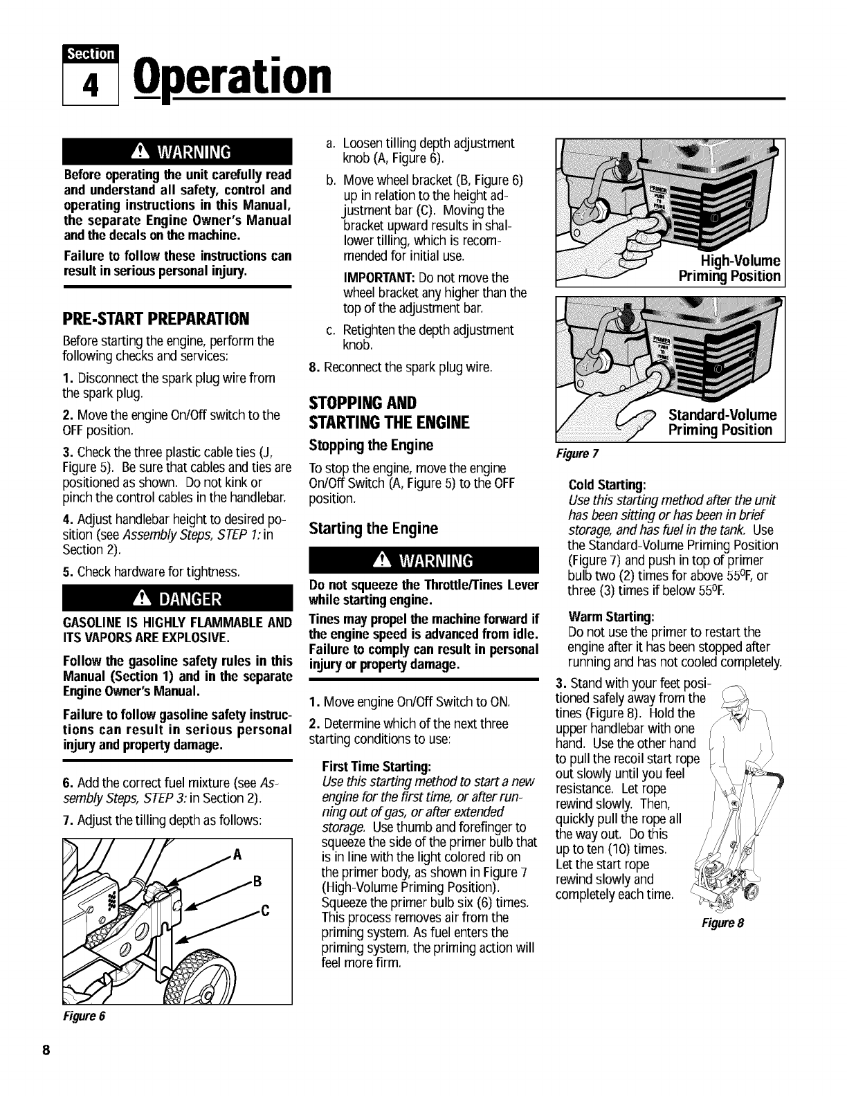
FirstTime Starting:
Usethis starting method to start a new
engine for the first time, or after run-
ning out of gas, or after extended
storage. Usethumb and forefinger to
squeezethe side of the primer bulb that
is in line with the light colored rib on
the primer body, as shown in Figure 7
(High-Volume Priming Position).
Squeezethe primer bulb six (6) times.
This process removes air from the
priming system. As fuel entersthe
priming system, the priming action will
feel more firm.
Figure 7
High-Volume
PrimingPosition
Position
ColdStarting:
Use this starting method after the unit
has been sitting or has beenin brief
storage, and has fuel in the tank. Use
the Standard-VolumePriming Position
(Figure 7) and push in top of primer
bulb two (2) times for above 55°1:,or
three (3) times if below 55OE
Warm Starting:
Do not use the primer to restart the
engineafter it has beenstopped after
running and has not cooled completely.
3. Stand with your feet posi-
tioned safely awayfrom the
tines (Figure 8). Hold the
upper handlebarwith one
hand. Usethe other hand
to pull the recoil start rope
out slowly until you feel
resistance. Let rope
rewind slowly. Then,
quickly pull the rope all
the way out. Do this
up to ten (10) times.
Let the start rope
rewind slowly and
completely each time.
Figure8
Section4: Operation
AC
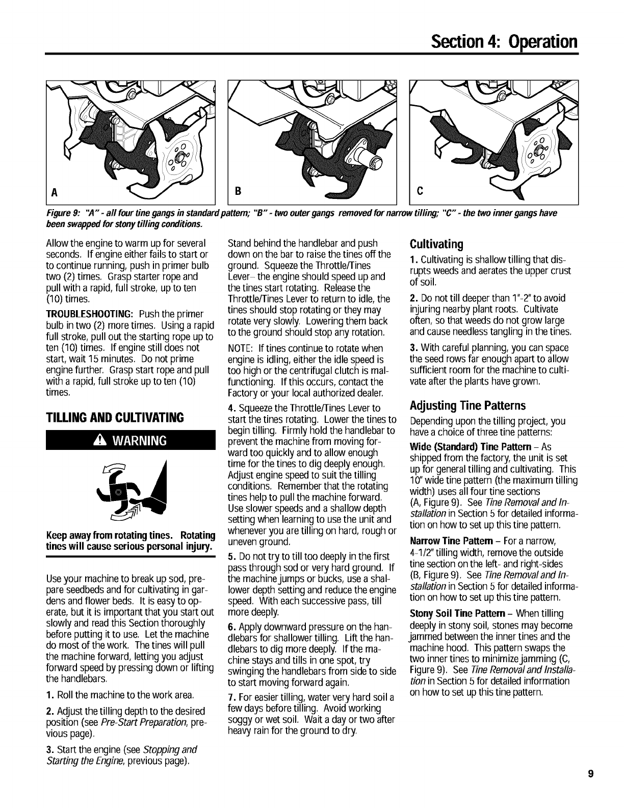
Figure 9: "A" -all four tine gangs in standardpattem; "B" -two outer gangs removed for narrow tilling; "C" -the two inner gangs have
been swappedfor stonytilling conditions.
Allow the engineto warm up for several
seconds. If engine either fails to start or
to continue running, push in primer bulb
two (2) times. Grasp starter rope and
pull with a rapid, full stroke, up to ten
(10) times.
TROUBLESHOOTING:Push the primer
bulb intwo (2) more times. Using a rapid
full stroke, pull out the starting rope up to
ten (10) times. If enginestill does not
start, wait 15 minutes. Do not prime
enginefurther. Graspstart rope and pull
with a rapid, full stroke up to ten (10)
times.
TILLINGANDCULTIVATING
Keepawayfromrotatingtines. Rotating
tineswill causeseriouspersonalinjury.
Useyour machineto break up sod, pre-
pare seedbedsand for cultivating in gar-
dens and flower beds. It is easyto op-
erate,but it is important that you start out
slowly and readthis Sectionthoroughly
before putting it to use. Let the machine
do most of the work. Thetines will pull
the machineforward, letting you adjust
forward speed by pressing down or lifting
the handlebars.
1. Roll the machineto the work area.
2. Adjust the tilling depth to the desired
position (see Pre-Start Preparation,pre-
vious page).
3. Start the engine (see Stopping and
Starting the Engine,previous page).
Stand behind the handlebar and push
down on the barto raise the tines off the
ground. Squeezethe Throttle/Tines
Lever- the engineshould speed up and
the tines start rotating. Releasethe
Throttle/TinesLever to return to idle, the
tines should stop rotating or they may
rotate very slowly. Lowering them back
to the ground should stop any rotation.
NOTE: If tines continue to rotate when
engine is idling, either the idle speed is
too high or the centrifugal clutch is mal-
functioning. If this occurs, contact the
Factoryor your local authorized dealer.
4. Squeezethe Throttle/TinesLeverto
start the tines rotating. Lower the tines to
begin tilling. Firmlyhold the handlebarto
prevent the machinefrom moving for-
ward too quickly and to allow enough
time for the tines to dig deeply enough.
Adjust enginespeed to suit the tilling
conditions. Rememberthat the rotating
tines helpto pull the machineforward.
Useslower speedsand a shallow depth
setting when learning to use the unit and
wheneveryou are tilling on hard, rough or
uneven ground.
5. Do not try to till too deeply in the first
pass through sod or very hard ground. If
the machinejumps or bucks, use a shal-
lower depth setting and reduce the engine
speed. With eachsuccessive pass, till
more deeply.
6. Apply downward pressure on the han-
dlebars for shallower tilling. Lilt the han-
dlebars to dig more deeply. If the ma-
chine stays andtills in one spot, try
swinging the handlebarsfrom side to side
to start moving forward again.
7. Foreasier tilling, water very hard soil a
few days before tilling. Avoid working
soggy or wet soil. Wait a day or two after
heavyrain for the ground to dry.
Cultivating
1. Cultivating is shallow tilling that dis-
rupts weeds and aeratesthe upper crust
of soil.
2. Do not till deeperthan 1"-2"to avoid
injuringnearby plant roots. Cultivate
often,so that weeds do not grow large
and cause needlesstangling in the tines.
3. With careful planning, you can space
the seed rows far enough apart to allow
sufficient room for the machineto culti-
vate alter the plants have grown.
AdjustingTinePatterns
Dependingupon the tilling project, you
havea choice of three tine patterns:
Wide (Standard)Tine Pattern- As
shipped from the factory, the unit is set
up for generaltilling and cultivating. This
10"wide tine pattern (the maximum tilling
width) uses all four tine sections
(A, Figure9). See TineRemovalandln-
stallation in Section 5 for detailed informa-
tion on how to set up this tine pattern.
Narrow Tine Pattern- Fora narrow,
4-1/2"tilling width, removethe outside
tine section on the left- and right-sides
(B, Figure9). See TineRemovaland In-
stallation in Section 5 for detailed informa-
tion on how to set up this tine pattern.
StonySoil Tine Pattern- When tilling
deeply instony soil, stones may become
jammed betweenthe inner tines and the
machinehood. This pattern swaps the
two innertines to minimizejamming (c,
Figure9). See Tinet?emovaland Installa-
tion in Section 5 for detailed information
on how to set up this tine pattern.
Section4: Operation
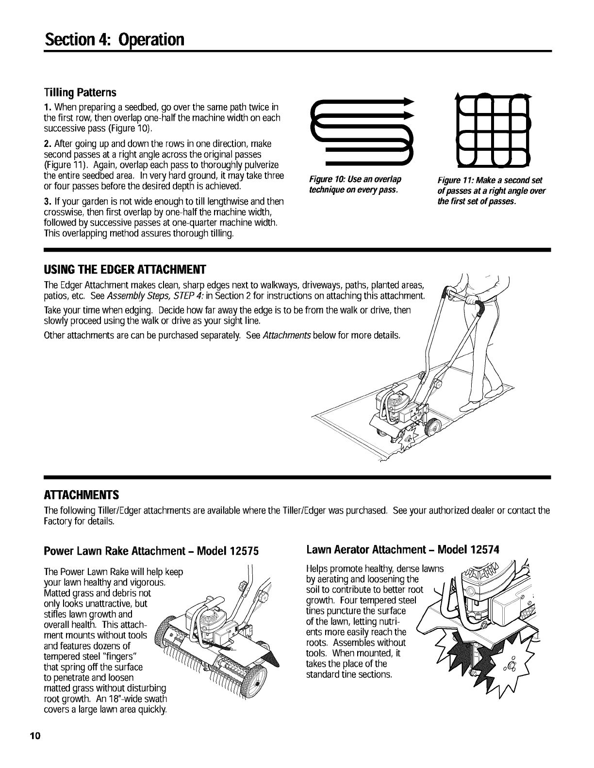
Tilling Patterns
1. When preparing a seedbed,go over the same path twice in
the first row, then overlap one-half the machinewidth on each
successivepass (Figure 10).
2. Alter going up and down the rows in one direction, make
second passesat a right angleacross the original passes
(Figure 11). Again, overlap each pass to thoroughly pulverize
the entire seedbed area. In very hardground, it may take three
or four passes before the desired depth is achieved.
3. If your garden is not wide enough to till lengthwise andthen
crosswise, then first overlap by one-half the machinewidth,
followed by successive passes at one-quarter machinewidth.
This overlapping method assures thorough tilling.
D
y
J
Figure 10: Use an overlap
techniqueon every pass. Figure 11:Make a secondset
of passesat a rightangle over
the firstset ofpasses.
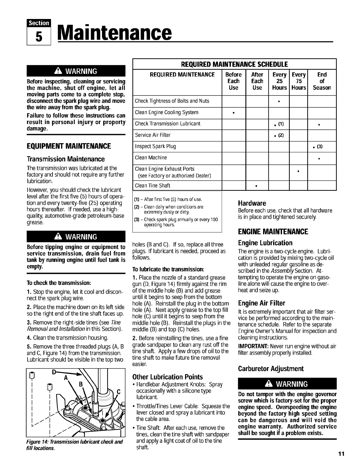
USINGTHEEDGERATTACHMENT
TheEdgerAttachment makesclean, sharp edges next to walkways, driveways, paths, planted areas,
patios, etc. SeeAssembly Steps, STEP4: in Section 2 for instructions on attaching this attachment.
Takeyour time when edging. Decidehow far awaythe edge is to be from the walk or drive, then
slowly proceed using the walk or drive as your sight line.
Other attachments arecan be purchasedseparately. SeeAttachments below for more details.
ATTACHMENTS
Thefollowing Tiller/Edger attachmentsare availablewhere the Tiller/Edgerwas purchased. Seeyour authorized dealeror contact the
Factoryfor details.
Power Lawn Rake Attachment -Model 12575
ThePower Lawn Rakewill help keep
your lawn healthy andvigorous.
Matted grass anddebris not
only looks unattractive, but
stifles lawn growth and
overall health. This attach-
ment mounts without tools
andfeatures dozensof
temperedsteel "fingers"
that spring off the surface
to penetrateand loosen
matted grass without disturbing
root growth. An 18"-wideswath
covers a large lawn areaquickly.
Lawn Aerator Attachment -Model 12574
Helps promote healthy,dense lawns
by aerating and loosening the
soil to contribute to better root
growth. Four tempered steel
tines puncture the surface
of the lawn, letting nutri-
ents more easily reach the
roots. Assembles without
tools. When mounted, it
takesthe place of the
standardtine sections.
10
s Maintenance
Before inspecting, cleaning or servicing
the machine, shut off engine, let all
movingparts come to a complete stop,
disconnectthe sparkplugwire and move
the wire away fromthe sparkplug.
Failure to follow these instructionscan
result in personal injury or property
damage.
EQUIPMENTMAINTENANCE
Transmission Maintenance
Thetransmission was lubricated at the
factory and should not require any further
lubrication.
However,you should check the lubricant
level after the first five (5) hours of opera-
tion and every twenty-five (25) operating
hours thereafter. If needed,use a high-
quality, automotive-grade petroleum-base
grease.
Before tipping engine or equipment to
service transmission, drain fuel from
tank by runningengine until fuel tank is
empty.
Tocheckthe transmission:
1. Stop the engine, let it cool and discon-
nect the spark plug wire.
2. Placethe machine down on its left side
so the right end of the tine shaft faces up.
3. Removethe right-side tines (see Tine
Removal and Installation in this Section).
4. Cleanthe transmission housing.
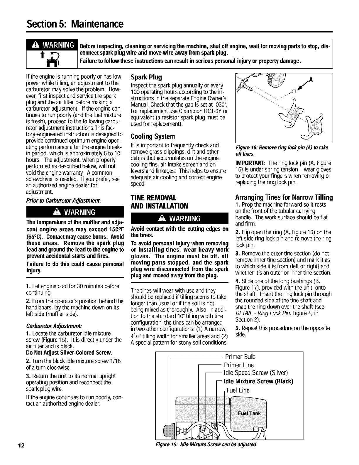
5. Removethe three threaded plugs (A, B
and C,Figure 14) from the transmission.
Lubricant should bevisible inthe top two
0 \ c
,'
'
I
Figure14:Transmissionlubricantcheckand
fill locations.
REQUIREDMAINTENANCESCHEDULE
REQUIREDMAINTENANCE
Check Tightness of Bolts and Nuts
Clean Engine Cooling System
Check Transmission Lubricant
Service Air Filter
Inspect Spark Plug
Clean Machine
Clean Engine Exhaust Ports
(see Factory or authorized Dealer)
CleanTine Shaft
(1) - After first five (5) hours of use.
(2) - Clean daily when conditions are
extremely dusty or dirty.
(3) - Check spark plug annually or every 100
operating hours,
Before After Every Every End
Each Each 25 75 of
Use Use Hours Hours Season
. (1)
°(2)
Hardware
,(3)
o
Before each use,check that all hardware
is in place andtightened securely.
I_IUI_.IlUI_ UAIMTI_MAM_I_
holes (B and C). If so, replaceall three
plugs. If lubricant is needed,proceed as
follows.
To lubricatethe transmission:
1. Placethe nozzleof a standard grease
gun (D, Figure14) firmly againstthe rim
of the middle hole (B) and add grease
until it begins to seepfrom the bottom
hole (A). Reinstallthe plug in the bottom
hole (A). Next apply greaseto the top fill
hole (C) until it begins to seepfrom the
middle hole (B). Reinstallthe plugs in the
middle (B) andtop (C) holes.
2. Before reinstalling the tines, use a fine
gradesandpaper to clean any rust off the
tine shaft. Apply a few drops of oil to the
tine shaft to makefuture tine removal
easier.
Other Lubrication Points
• HandlebarAdjustment Knobs: Spray
occasionally with a silicone type
lubricant.
• Throttle/TinesLeverCable: Squeezethe
lever closed and spray a lubricant into
the cable area.
• TineShaft: Alter each use,removethe
tines, clean the tine shaft with sandpaper
and apply a light coatof oil to the tine
shaft.
Engine Lubrication
The engineis a two-cycle engine. Lubri-
cation is provided by mixing two-cycle oil
with unleadedregular gasoline as de-
scribed in the AssemblySection. At-
tempting to operatethe engineon gaso-
line alonewill causethe engineto over-
heat andseizeup.
Engine Air Filter
It is extremely important that air filter ser-
vice be performed according to the main-
tenanceschedule. Referto the separate
EngineOwner's Manual for inspection and
cleaning instructions.
IMPORTANT:Neverrun enginewithout air
filter assemblyproperly installed.
Carburetor Adjustment
Do not tamper with the engine governor
screwwhich is factory-setfor the proper
enginespeed, Overspeedingthe engine
beyond the factory high speed setting
can be dangerous and will void the
engine warranty, Authorized service
shall be soughtif a problemexists,
11
Section5: Maintenance
ir !IiY_Vl-'I:_L_IIL_[fll Beforeinspecting,cleaning or servicingthe machine, shutoff engine, wait for movingpartsto stop, dis-
connectsparkplug wire and movewire awayfromsparkplug.
Failure to followthese instructionscan result in seriouspersonal injuryor propertydamage.
If the engine is running poorly or has low
power while tilling, an adjustment to the
carburetor may solvethe problem. How-
ever,first inspect and service the spark
plug andthe air filter before making a
carburetor adjustment. If the enginecon-
tinues to run poorly (and the fuel mixture
is fresh), proceedto the following carbu-
retor adjustment instructions.This fac-
tory-engineered instruction is designedto
provide continued optimum engine oper-
ating performance afterthe enginebreak-
in period, which is approximately 5 to 10
hours. The adjustment, when properly
performed as described below, will not
void the enginewarranty. A common
screwdriver is needed. If you prefer,see
an authorizedengine dealerfor
adjustment.
Prior to CarburetorAdjustment:
Thetemperatureof the muffler and adja-
cent engine areas may exceed 150OF
(65°C). Contactmaycauseburns. Avoid
these areas. Remove the spark plug
lead andgroundthe lead to the engineto
preventaccidentalstarts andfires.
Failure to do this could cause personal
injury.
1. Let enginecool for 30 minutes before
continuing.
2. From the operator's position behind the
handlebars, lay the machinedown on its
left side (muffler side).
CarburetorAdJustment:
1. Locatethe carburetor idle mixture
screw (Figure 15). It is directly underthe
air filter and is black.
Do Not AdJustSilver-ColoredScrew.
2. Turn the black idle mixture screw 1/16
of a turn clockwise.
3. Return the unit to its normal upright
operating position and reconnect the
spark plug wire.
If the enginecontinues to run poorly, con-
tact an authorizedengine dealer.
Spark Plug
Inspectthe spark plug annually or every
100 operating hours according to the in-
structions in the separate EngineOwner's
Manual. Checkthat the gap is set at .030".
For replacementuse Champion RCJ-6Yor
equivalent (a resistor spark plug must be
used for replacement).
Cooling System
It is important to frequently check and
remove grass clippings, dirt and other
debris that accumulateson the engine,
cooling fins, air intakescreen and on
leversand linkages. This helps to ensure
adequateair cooling and correct engine
speed.
TINE REMOVAL
AND INSTALLATION
Avoid contactwith the cutting edges on
the tines.
To avoid personal injurywhen removing
or installing tines, wear heavy work
gloves. The engine must be off, all
moving parts stopped, and the spark
plug wire disconnectedfrom the spark
plugand movedaway fromthe plug.
Thetines will wear with use and they
should be replaced if tilling seems to take
longerthan usual or if the soil is not
being mixed as thoroughly. Also, in addi-
tion to the standard 10"tilling width tine
configuration, the tines can be arranged
in two other configurations: (1) A narrow,
41/2"tilling width for smaller areasand (2)
A special pattern for stony soil conditions.
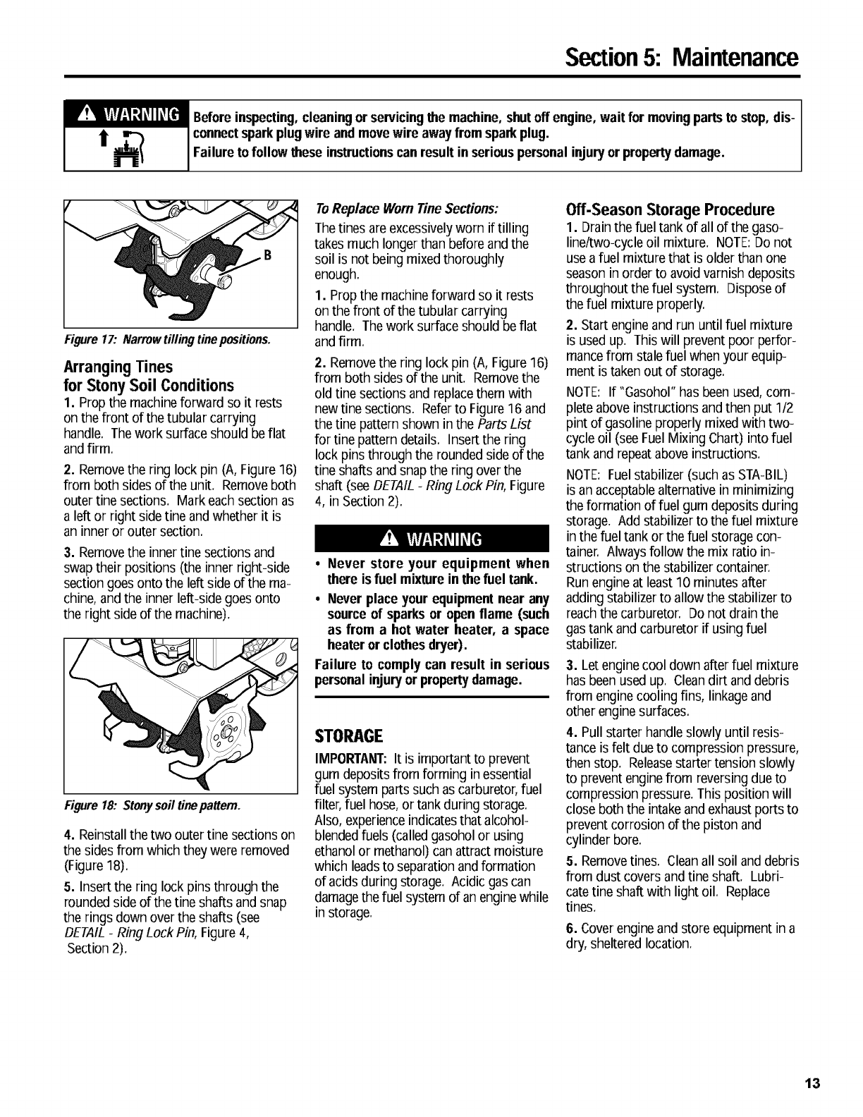
Figure 16:Remove ring lockpin (A) to take
off tines.
IMPORTANT:Thering lock pin (A, Figure
16) is under spring tension -wear gloves
to protect your fingers when removing or
replacing the ring lock pin.
Arranging Tines for Narrow Tilling
1. Propthe machineforward so it rests
on the front of the tubular carrying
handle. The work surface should beflat
andfirm.
2. Flip openthe ring (A, Figure16) on the
left side ring lock pin and remove the ring
lock pin.
3. Removethe outer tine section (do not
remove inner tine section) and mark it as
to which side it is from (left or right) and
whether it's an outer or innertine section.
4. Slide one of the long bushings (B,
Figure 17), provided with the unit, onto
the shaft. Insert the ring lock pin through
the rounded side of the tine shaft and
snap the ring down over the shaft (see
DETAIL-Ring Lock Pin, Figure 4, in
Section 2).
5. Repeatthis procedure on the opposite
side.
Primer Bulb
Primer Line
-- Idle Speed Screw (Silver)
Idle Mixture Screw (Black)
Fuel Line
12 Figure15:IdleMixtureScrewcanbeadjusted.
Section5: Maintenance
IrT_flfl-_l;]t,_l lt,_[1_ Beforeinspecting,cleaning orservicingthe machine, shutoff engine, wait for movingpartsto stop, dis-
]j, _connectsparkplugwire and movewire awayfrom sparkplug.
Failure to follow these instructionscan result in seriouspersonal injuryor propertydamage,
Figure 17: Narrow tilling tine positions.
Arranging Tines
for Stony Soil Conditions
1. Prop the machineforward so it rests
on the front of the tubular carrying
handle. The work surface should be flat
andfirm.
2. Removethe ring lock pin (A, Figure 16)
from both sides of the unit. Remove both
outer tine sections. Mark each section as
a left or right side tine andwhether it is
an inner or outer section.
3. Removethe innertine sections and
swap their positions (the inner right-side
section goes onto the left side of the ma-
chine, and the inner lelt-side goes onto
the right side of the machine).
Figure 18: Stonysoil tinepattern.
4. Reinstall the two outertine sections on
the sidesfrom which they were removed
(Figure 18).
5. Insert the ring lock pins through the
rounded side of the tine shafts and snap
the rings down over the shafts (see
DETAIL-Ring Lock Pin, Figure 4,
Section 2).
ToReplace Wornfine Sections:
Thetines are excessivelyworn iftilling
takes much longer than before and the
soil is not being mixed thoroughly
enough.
1. Prop the machineforward so it rests
on the front of the tubular carrying
handle. Thework surface should be flat
and firm.
2. Removethe ring lock pin (A, Figure16)
from both sides of the unit. Removethe
old tine sections and replacethem with
new tine sections. Referto Figure16 and
the tine pattern shown in the Parts List
for tine pattern details. Insert the ring
lock pins through the rounded side of the
tine shafts and snap the ring over the
shaft (see DETAIL-Ring Lock Pin, Figure
4, in Section 2).
•Never store your equipment when
there is fuel mixture in the fuel tank.
•Never place your equipment near any
source of sparksor open flame (such
as from a hot water heater, a space
heateror clothesdryer).
Failure to comply can result in serious
personalinjury or propertydamage.
STORAGE
IMPORTANT:It is importantto prevent
gum deposits from forming inessential
fuel system parts such as carburetor, fuel
filter, fuel hose, or tank during storage.
Also, experienceindicatesthat alcohol-
blendedfuels (called gasohol or using
ethanol or methanol)can attract moisture
which leadsto separationand formation
of acids during storage. Acidic gas can
damagethe fuel system of an enginewhile
in storage.
Off-Season Storage Procedure
1. Drain the fuel tank of all of the gaso-
line/two-cycle oil mixture. NOTE:Do not
use a fuel mixture that is older than one
season in order to avoid varnish deposits
throughout the fuel system. Dispose of
the fuel mixture properly.
2. Start engine and run until fuel mixture
is used up. Thiswill prevent poor perfor-
mancefrom stalefuel when your equip-
ment is taken out of storage.
NOTE: If "Gasohol" has beenused, com-
plete above instructions and then put 1/2
pint of gasoline properly mixed with two-
cycle oil (see FuelMixing Chart) into fuel
tank and repeat above instructions.
NOTE: Fuelstabilizer (such as STA-BIL)
is an acceptablealternative in minimizing
the formation of fuel gum deposits during
storage. Add stabilizer to the fuel mixture
in the fuel tank or the fuel storage con-
tainer. Always follow the mix ratio in-
structions on the stabilizer container.
Run engine at least 10 minutes alter
adding stabilizer to allow the stabilizer to
reach the carburetor. Do not drain the
gas tank and carburetor if using fuel
stabilizer.
3. Letengine cool down after fuel mixture
has been used up. Clean dirt and debris
from engine cooling fins, linkage and
other enginesurfaces.
4. Pull starter handle slowly until resis-
tance is felt due to compression pressure,
then stop. Releasestarter tension slowly
to prevent enginefrom reversing due to
compression pressure. Thisposition will
close both the intake and exhaust ports to
prevent corrosion of the piston and
cylinder bore.
5. Removetines. Cleanall soil anddebris
from dust covers and tine shaft. Lubri-
catetine shaft with light oil. Replace
tines.
6. Coverengineand store equipment in a
dry, sheltered location.
13
Section5: Maintenance
Beforeinspecting,cleaning orservicingthe machine, shutoff engine, wait for movingpartsto stop, dis-
connectsparkplug wire and movewire awayfromsparkplug.
Failure to followthese instructionscan result in seriouspersonal injuryor propertydamage.
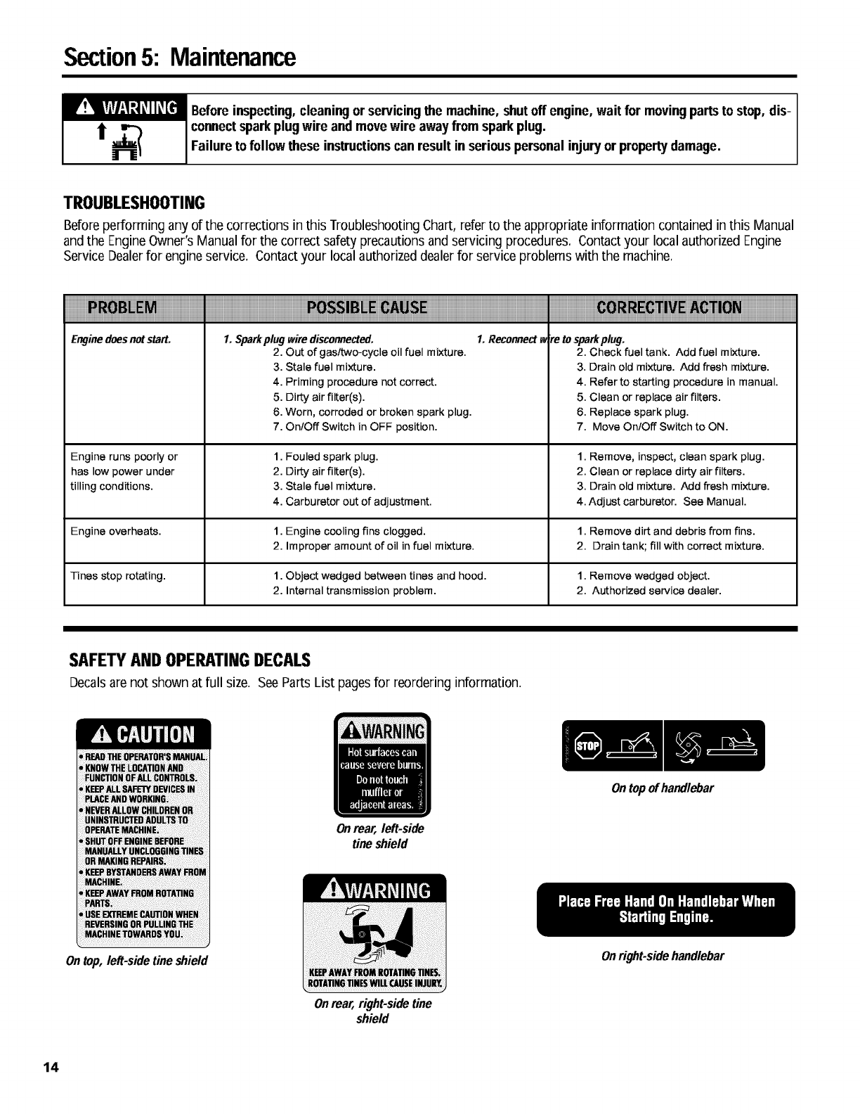
TROUBLESHOOTING
Before performing any of the corrections in this Troubleshooting Chart, refer to the appropriate information contained in this Manual
andthe EngineOwner'sManual for the correct safety precautions and servicing procedures. Contactyour local authorized Engine
Service Dealerfor engine service. Contact your local authorized dealerfor service problems with the machine.
iiiiiiiiiiiiiiiiiiiiiiiiiiiiiiiiiiIiiiiiiiiiiiiiiiiiiiiiiiiiiiiiiiiiiiiiiiiiiiiiiiiiiiiiiiiiiiiiiiiiiiiiiiii! iiiiiiiii iiiiiiiiiiiii
Enginedoes notstart. 1. Sparkplug wire disconnected. 1. Reconnect_zre to sparkplug.
2. Out of gasltwo-cycle oil fuel mixture. 2. Check fuel tank. Add fuel mixture.
3. Stale fuel mixture. 3. Drain old mixture. Add fresh mixture.
Engine runs poorly or
has low power under
tilling conditions.
4. Priming procedure not correct.
5. Dirty air filter(s).
6. Worn, corroded or broken spark plug.
7. OnlOff Switch in OFF position.
1. Fouled spark plug.
2. Dirty air filter(s).
3. Stale fuel mixture.
4. Carburetor out of adjustment.
4. Refer to starting procedure in manual.
5. Clean or replace air filters.
6. Replace spark plug.
7. Move OnlOff Switch to ON.
1. Remove, inspect, clean spark plug.
2. Clean or replace dirty air filters.
3. Drain old mixture. Add fresh mixture.
4. Adjust carburetor. See Manual.
Engine overheats. 1. Engine cooling fins clogged. 1. Remove dirt and debris from fins.
2. Improper amount of oil in fuel mixture. 2. Drain tank; fill with correct mixture.
Tines stop rotating. 1. Object wedged between tines and hood. 1. Remove wedged object.
2. Internal transmission problem. 2. Authorized service dealer.
SAFETYAND OPERATINGDECALS
Decals arenot shown at full size. SeeParts List pagesfor reordering information.
Ontop, left-side tine shield
Onrear, left-side
tine shield
Onrear, right-side tine
shield
Ontop ofhandlebar
Onright-side handlebar
14

Model 12097 Parts List
A
B 9
B
A14, 15
20
14,15
22
23
11,12 \22
TRANSMISSIONASSEMBLY
Ref # Part #
1 1915039
3
4
5
6
7
8
1915040
1983632
1918307
1983731
1983636
1983637
1904416
9 1909923
10 1185741
11 1111600
Description City.
Transmission Case - left-side,
(incl, pressed-in bushing) ............ 1
Transmission Case -right-side,
(incl, pressed-in bushing) ............ 1
OilSeal ............................. 2
Worm Input Shaft Assembly ............. 1
Input Bearing ........................ 2
ThrustBearing ....................... 1
Ball Bearing .......................... 1
Shaft Assembly, (Incl, pressed-on worm
gear andtwo ring lockpins) ........... 1
OilSeal, Input ........................ 1
Plug, 1/8 ............................ 3
HexScrew, 1/4-20 x 7/8 (five locations,
identified as "A" on transmission case) ,, 5
Ref# Part #
12 1100069
13 1817146
14 1983635
15 1983640
16 1983641
17 1983642
18 1983638
19 1107381
20 1983663
21 1909486
22 1747166
23 1915055
24 1983713
Description City.
HexScrew, 114-20x 1 (three locations,
identified as "B" on transmission case) ,, 3
Locknut, Nyloc, 1/4"-20 ................. 8
Thrust Washer,output (,050") ............ NR
Thrust Washer,output (,040") ............ NR
Thrust Washer,input (,020") ............. NR
Thrust Washer,input (,035") ............. NR
Thrust Washer ........................ 2
FlatWasher, 1/4 ...................... 2
Hex Hal,Screw, 114-20x 5 .............. 2
Clutch Drum and Hub .................. 1
Set Screw, 1/4-28 x 3/8 ................. 4
Dust Cover .......................... 2
FeltWasher .......................... 2
AIR - As Required
15
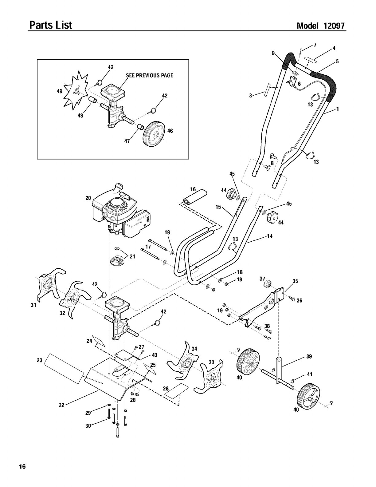
PartsList Model 12097
42
48
SEEPREVIOUSPAGE
18
16
45
!13
31
23
32
22
42
16
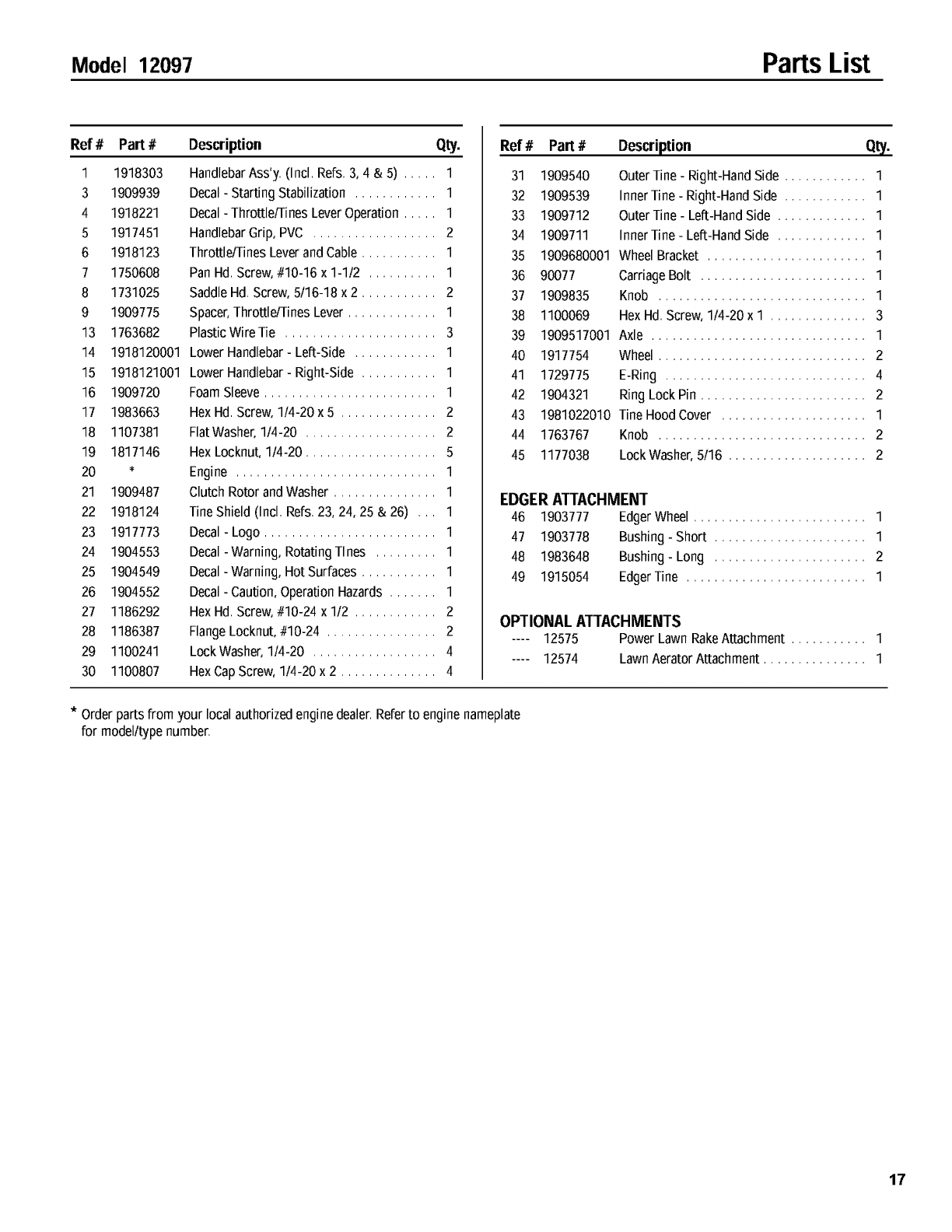
Model 12097 Parts List
Ref # Part #
1 1918303
3 1909939
4 1918221
5 1917451
6 1918123
71750608
8 1731025
9 1909775
13 1763682
14 1918120001
15 1918121001
16 1909720
17 1983663
18 11O7381
19 1817146
20 *
21 1909487
22 1918124
23 1917773
24 1904553
25 1904549
26 1904552
27 1186292
28 1186387
29 1100241
3O 1100807
Description Qty.
HandlebarAss'y, (Incl, Refs, 3, 4 & 5) ..... 1
Decal- Starting Stabilization ............ 1
Decal- Throttle/Tines LeverOperation ..... 1
HandlebarGrip, PVC .................. 2
Throttle/Tines Leverand Cable ........... 1
Pan Hd, Screw, 7/10-16x 1-112 .......... 1
Saddle Hd, Screw, 5116-18 x 2 ........... 2
Spacer, Throttle/Tines Lever ............. 1
Plastic Wire Tie ...................... 3
Lower Handlebar- Lefl-Side ............ 1
Lower Handlebar- Right-Side ........... 1
FoamSleeve ......................... 1
Hex Hd, Screw, 114-20 x 5 .............. 2
FlatWasher, 114-20 ................... 2
Hex Locknut, 114-20 ................... 5
Engine ............................. 1
Clutch Rotor and Washer ............... 1
Tine Shield (Incl, Refs, 23, 24, 25 & 26) ,,, 1
Decal - Logo ......................... 1
Decal - Warning, Rotating Tines ......... 1
Decal- Warning, Hot Surfaces ........... 1
Decal- Caution, Operation Hazards ....... 1
Hex Hd, Screw, 7/10-24x 112 ............ 2
FlangeLocknut, 7/10-24 ................ 2
LockWasher, 114-20 .................. 4
HexCap Screw, 114-20 x 2 .............. 4
Ref # Part #
31 1909540
32 1909539
33 1909712
34 1909711
35 1909680001
36 90077
37 1909835
38 1100069
39 1909517001
4O 1917754
41 1729775
42 1904321
43 1981022010
44 1763767
45 1177038
Description Qty.
Outer Tine - Right-Hand Side ............ 1
Inner Tine - Right-Hand Side ............ 1
Outer Tine - Lefl-Hand Side ............. 1
Inner Tine - Lefl-Hand Side ............. 1
Wheel Bracket ....................... 1
Carriage Bolt ........................ 1
Knob .............................. 1
Hex Hd, Screw, 114-20 x I .............. 3
Axle ............................... 1
Wheel .............................. 2
E-Ring ............................. 4
Ring Lock Pin ........................ 2
Tine Hood Cover ..................... 1
Knob .............................. 2
LockWasher, 5116 .................... 2
EDGERATTACHMENT
46 1903777 EdgerWheel ......................... 1
47 1903778 Bushing- Short ...................... 1
48 1983648 Bushing- Long ...................... 2
49 1915054 EdgerTine .......................... 1
OPTIONAL ATTACHMENTS
.... 12575 Power Lawn RakeAttachment ........... 1
.... 12574 LawnAerator Attachment ............... 1
*Orderpartsfrom yourlocalauthorizedenginedealer,Referto enginenameplate
for modelltypenumber,
17

Notes
18
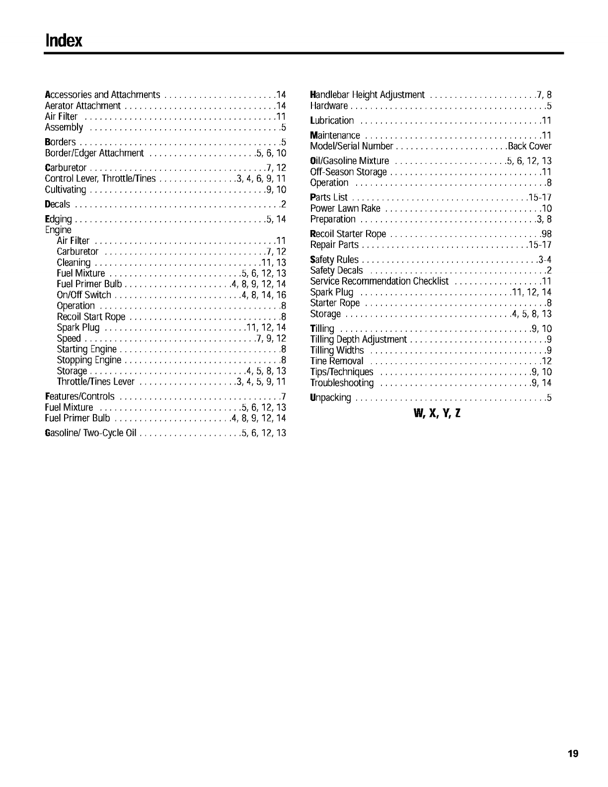
Index
AccessoriesandAttachments ....................... 14
Aerator Attachment ............................... 14
Air Filter ....................................... 11
Assembly ....................................... 5
Borders......................................... 5
Border/EdgerAttachment ...................... 5, 6, 10
Carburetor .................................... 7, 12
Control Lever,Throttle/Tines ................ 3, 4, 6, 9, 11
Cultivating .................................... 9, 10
Oecals .......................................... 2
Edging ....................................... 5, 14
Engine
Air Filter ..................................... 11
Carburetor ................................. 7, 12
Cleaning .................................. 11, 13
Fuel Mixture ........................... 5, 6, 12, 13
Fuel Primer Bulb ...................... 4, 8, 9, 12, 14
On/Off Switch .......................... 4, 8, 14, 16
Operation ..................................... 8
Recoil Start.Rope ............................... 8
Spark Plug ............................. 11, 12, 14
Speed ................................... 7, 9, 12
Starting Engine................................. 8
Stopping Engine ................................ 8
Storage ................................ 4, 5, 8, 13
Throttle/Tines Lever .................... 3, 4, 5, 9, 11
Features/Controls ................................. 7
Fuel Mixture ............................. 5, 6, 12, 13
Fuel Primer Bulb ........................ 4, 8, 9, 12, 14
Gasoline/Two-CycleOil ..................... 5, 6, 12, 13
HandlebarHeight Adjustment ...................... 7, 8
Hardware ........................................ 5
Lubrication ..................................... 11
Maintenance .................................... 11
Model/Serial Number ....................... BackCover
Oil/GasolineMixture ....................... 5, 6, 12, 13
Off-SeasonStorage ............................... 11
Operation ....................................... 8
Parts List .................................... 15-17
Power Lawn Rake ................................ 10
Preparation .................................... 3, 8
RecoilStarter Rope ............................... 98
Repair Parts .................................. 15-17
Safety Rules .................................... 3-4
Safety Decals .................................... 2
Service RecommendationChecklist .................. 11
Spark Plug ............................... 11, 12, 14
Starter Rope ..................................... 8
Storage .................................. 4, 5, 8, 13
Tilling ....................................... 9, 10
Tilling Depth Adjustment ............................ 9
Tilling Widths .................................... 9
Tine Removal ................................... 12
Tips/Techniques ............................... 9, 10
Troubleshooting ............................... 9, 14
Unpacking ....................................... 5
W,X, Y,Z
19
CUSTOMERSERVICEINFORMATION
OwnerRegistrationCard
Pleasefill out and mail the enclosed owner
registration card. The purpose of this card is
to register each unit at the factory so that we
can provide you with warranty benefits and in-
formational bulletins.
WarrantyService
Thewarranty statement is included in the unit's literature
package.
Model/Serial Numbers
A Model/Serial Numbers decal is locatedon the handlebar.
For ready reference, record these numbers inthe spaces
below.
Dateof Purchase:
Model Number:
Serial Number:
AuthorizedDealer Information
If you purchasedyour unit from an authorizeddealer, record
the dealer's addressand phone number below for ready
reference:
DealerName:
Address:
Phone:
IMPORTANT:
Left and rightsidesof the unit are determined by standing
behindthe unit, in the operator'sposition,andfacing in the
directionof forwardtravel.
NOTICE:
We reservethe rightto changespecifications,add im-
provements or discontinuethe manufactureof any of our
equipment withoutnoticeor obligationto purchasers of our
equipment.
CustomerServiceandTechnical Service
If you havequestions or problems with the
unit, contact your localdealer or the factory.
(When calling or writing, provide the
Model/Serial Numbers of the unit.)
ReplacementParts
Factoryspecified replacement parts are
availablefrom your authorizeddealer or di-
rectly from the factory. When ordering
parts, besure to provide the following:
• Model/Serial Numbers of the unit.
• Part number of the part needed.
• Part Description.
• Quantity needed.
NOTE:All replacementparts must conform
to our rigid quality specifications. Although
some replacement parts we provide may vary slightly in
shape,color or texture from the original parts, any variations
will not affect the fit or performance of these parts on your
unit.
EngineServiceand Repair
Forengineservice or repair, contact your
nearestauthorized enginedealer (look in the _,,,
Yellow Pagesunder "Engines-Gasoline").
Theengine is warranted by the engine man-
ufacturer.Any unauthorizedwork performed
on the engineduring the warranty period
mayvoid this warranty. For complete de-
tails on the engine warranty, refer to the
engineowner manual.
We urge using only genuine replacement parts, which
meet all the latest requirements. Replacement parts
manufacturedby otherscouldpresentsafetyhazards,even
though they mayfit onthe unit.
For customerassistance,contactyour nearestauthorizeddealer or:
GARDENWAY INCORPORATED • 1 GardenWay •Troy,NewYork 12180
CustomerService:1-800-437-8686 • TechnicalService:1-800-520-5520 • PartsService:1-800-648-6776
• FAX:(518) 233-4622 • WEBSITE:www.troybilt.com
Outsidethe United States and Canada:
CustomerService:(518) 233-4807 • TechnicalService:(518) 233-4808 • PartsService:(518) 233-4806 • FAX(518) 233-4622
1905613 (12/00) Printed in U,S,A, © 2000 Garden Way Incorporated
