Troybilt 12AF753B063 User Manual MOWER Manuals And Guides L0404261
TROYBILT Walk Behind Lawnmower, Gas Manual L0404261 TROYBILT Walk Behind Lawnmower, Gas Owner's Manual, TROYBILT Walk Behind Lawnmower, Gas installation guides
User Manual: Troybilt 12AF753B063 12AF753B063 TROYBILT MOWER - Manuals and Guides View the owners manual for your TROYBILT MOWER #12AF753B063. Home:Lawn & Garden Parts:Troybilt Parts:Troybilt MOWER Manual
Open the PDF directly: View PDF ![]() .
.
Page Count: 42

0TRtII BILT --
Operator's Manual
Wide-CutTM 33"
Combination Mower
Models 753B
F753B
(fuel tank styles vary by engine model)
IMPORTANT:READ SAFETY RULES AND INSTRUCTIONS CAREFULLY
Warning: This unit is equipped with an internal combustion engine and should not be used on or near any unimproved forest-covered, brush-cov-
ered or grass-covered land unless the engine's exhaust system is equipped with a spark arrester meeting applicable local or state laws (if any). If a
spark arrester is used, it should be maintained in effective working order by the operator. In the State of California the above is required by law
(Section 4442 of the California Public Resources Code). Other states may have similar laws. Federal laws apply on federal lands. A spark arrester
for the muffler is available by contacting the service department at Troy-Bilt LLC, P.O. Box 361131 Cleveland, Ohio 44136-0019.
TROY-BILT LLC, P.O. BOX 361131, CLEVELAND, OH 44136-0019
PRINTED IN USA FORM NO. 770-10602E
(03/2003)
TABLEOFCONTENTS
Content Page
Safety ................................................................... 1
Assembly................................................................. 4
Features and Controls....................................................... 8
Operation ................................................................ 11
Maintenance .............................................................. 16
Off-Season Storage ........................................................ 24
Lubrications............................................................... 25
Troubleshooting ........................................................... 27
Parts List................................................................. 28
Warrany Information ........................................................ Back Cover
FINDINGMODELNUMBER
This Operator's Manual is an important part of your new Wide-Cut TM mower. It will help you assemble, prepare and
maintain the unit for best performance. Please read and understand what it says.
Before you start assembling your new equipment, please locate the model plate on the equipment and copy the infor-
mation from it in the space provided below. This information is very important if you need help from our Customer
Support Department or an authorized dealer.
You can locate the model number by looking at the rear surface of the tine shield. A sample model plate is ex-
plained below. For future reference, please copy the model number and the serial number of the equipment in
the space below
OTRItV BILT. TROY-BILT LLC
P. 0. BOX 361131
www.troybilt.com CLEVELAND, 0H44136
330-558-7220
_. 866-840-6483_
Copy Model Number Here
Copy Serial Number Here
ENGINEINFORMATION
The engine manufacturer is responsible for all engine-related issues with regards to performance, power-rating,
specifications, warranty and service. Please refer to the engine manufacturer's Owner's/Operator's Manual packed
separately with your unit for more information.
CALLINGCUSTOMERSUPPORT
If you have difficulty assembling this product or have any questions regarding the controls, operation or maintenance
of this unit, please call the Customer Support Department.
Call 1- (330) 558-7220 or 1- (866) 840-6483 to reach a Customer Support representative. Please have
your unit's model number and serial number ready when you call. See previous section to locate this in-
formation. You will be asked to enter the serial number in order to process your call.
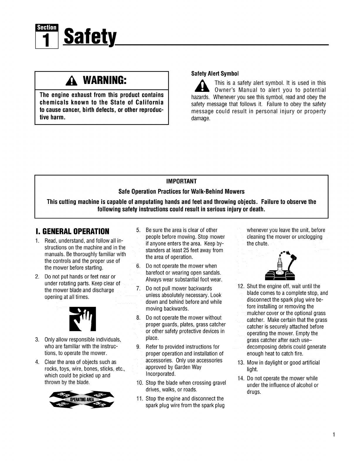
Safety
WARNING:
The engine exhaust from this product contains
chemicals known to the State of California
to cause cancer, birth defects, or other reproduc-
tive harm.
SafetyAlert Symbol
_, his is a safety alert symbol. It is used in this
Owner's Manual to alert you to potential
hazards. Wheneveryou seethis symbol, readand obeythe
safety message that follows it. Failureto obey the safety
message could result in personal injury or property
damage.
IMPORTANT
Safe Operation Practicesfor Walk-Behind Mowers
This cutting machine is capable of amputating hands and feet and throwing objects. Failure to observethe
following safety instructions could result in serious injury or death.
I. GENERALOPERATION
1.
.
Read,understand,andfollow all in-
structions on the machineandin the
manuals.Bethoroughlyfamiliar with
the controls andthe proper useof
the mower beforestarting.
Do not put handsor feet nearor
under rotatingparts. Keepclear of
the mower bladeand discharge
openingat all times.
3. Onlyallow responsibleindividuals,
who arefamiliar with the instruc-
tions, to operatethe mower.
4. Clearthe areaof objectssuch as
rocks,toys, wire, bones,sticks, etc.,
which could be pickedupand
thrown by the blade.
.
5. Besurethe areais clear of other
peoplebeforemowing. Stop mower
if anyoneentersthe area. Keepby-
standersat least25 feetawayfrom
the areaof operation.
6. Do not operatethe mowerwhen
barefootor wearingopensandals.
Always wearsubstantialfoot wear.
Do not pull mower backwards
unlessabsolutelynecessary.Look
down and behindbeforeand while
moving backwards.
8. Do not operatethe mowerwithout
properguards,plates,grasscatcher
or other safetyprotectivedevicesin
place.
9. Referto providedinstructions for
properoperationand installationof
accessories.Only useaccessories
approvedby GardenWay
Incorporated.
10. Stop the bladewhencrossing gravel
drives,walks, or roads.
11. Stop the engineand disconnectthe
sparkplug wire from the sparkplug
wheneveryou leavethe unit, before
cleaningthe moweror unclogging
the chute.
12. Shutthe engineoff, wait until the
blade comesto a completestop, and
disconnectthe spark plugwire be-
fore installing or removingthe
mulchercoveror the optionalgrass
catcher. Makecertainthat the grass
catcher is securelyattachedbefore
operatingthe mower. Emptythe
grass catcheraftereach use-
decomposingdebris could generate
enoughheatto catch fire.
13. Mow in daylightor goodartificial
light.
14. Do not operatethe mowerwhile
underthe influenceof alcohol or
drugs.
Section1: Safety
15.
16.
17.
Neveroperatemowerin wet grass.
Always besure of your footing; keep
a firm hold onthe handleandwalk;
never run.
Disengagethe Wheel DriveLeveron
self-propelledmodelsbeforestarting
the engine.
If the unit should start to vibrateab-
normally, stop the engineanddis-
connectthe sparkplug wire. Then
check immediatelyfor the cause.
Vibration is generallya warning of
trouble.
18. Alwayswear safetygogglesor safety
glasseswith side shieldswhen oper-
ating mower.
19. Watchfor traffic when operating
near, or when crossing roadways.
20. Neverattemptto carrychildren or
other passengerson the mower.
Theycouldfall off and beseriously
injured, or theycould interferewith
the safeoperationof the mower.
21. Checkthe operationof the Operator
PresenceControlBarbeforeeach
use.Seethe MaintenanceSectionof
this manualfor instructions. If the
engineruns longerthan three sec-
onds after the OperatorPresence
Control Baris released,the system
is not working properly. Immediately
contactyour local servicedealeror
the factory TechnicalService
Departmentfor instructions. Do not
usethe moweruntil the mechanism
is repaired.
22. The moweris equippedwith a safety
dischargechute, comeswith special
mulchercovers,and offers an op-
tional grass catcher. The safetydis-
chargechute must beworking prop-
erly at alltimes. Neverattemptto
disconnector otherwisecausethis
dischargechuteto ceaseworking. If
used,mulchercover or grass
catcherattachmentmust beinstalled
properly andfunction correctly. Do
not useyour equipmentotherwise.
23. Neverrun the enginein an enclosed
area.Engineexhaustcontainscarbon
monoxide,a deadlygasthat is odor-
less, colorless,andtasteless.Always
runthe engineoutdoorsand make
sure there is adequateventilation.
II. SLOPEOPERATION IV. SERVICE
Slopesare a majorfactorrelatedto
slip andfall accidentswhichcanresult
in severeinjury. All slopesrequire
extracaution.If youfeel uneasyona
slope,donotmowit.
DO:
Mow acrossthe faceof slopes;never
upand down. Exerciseextremecau-
tion when changingdirection on
slopes.Avoid slopesgreaterthan
150.
Removeobjectssuch as rocks,tree
limbs, etc.
Watch for holes,ruts, or bumps. Tall
grass can hideobstacles.
DONOT:
1. Useextracare in handlinggasoline
andother fuels. Theyareflammable
andtheir vaporsare explosive.
a) Useonly an approvedcontainer.
b) Neverremovegas cap or add
fuel when the engineis running.
Allow engineto cool before refu-
eling. Do not smoke.
c) Neverrefuelthe machine
indoors.
d) Neverstore the machineor fuel
containerinsidewhere there is
an openflame, such as awater
heater,etc.
e) Movemowerawayfrom any
gasolinefumes beforestarting
the engine.
2. Neverrunan engineinside aclosed
area.
III. CHILDREN
Tragicaccidentscanoccurif the opera-
toris notalertto the presenceof chil-
dren.Childrenare oftenattractedtothe
mowerandtothe mowingactivity.
Neverassumethat childrenwill remain
whereyoulastsawthem.
1. Keepchildren out of the mowing
areaand underthewatchful careof
a responsibleadult.
Bealert andturn moweroff if chil-
drenenter the area.
.
3.
4. Neverallow children to operatethe
mower.
5. Useextracarewhen approaching
blind corners, shrubs,trees, or other
objectsthat mayobscurevision.
Beforeandwhile movingbackwards,
look behindand down for small
children.
3. Nevermakeadjustmentsor repairs
with the enginerunning. Disconnect
the sparkplug wire and keepthe
wire awayfrom the plugto prevent
accidentalstarting.
Keepall nuts andbolts, especially
the bladeattachmentbolts,tight and
keepequipmentin goodcondition.
Nevertamperwith safety devices.
Checktheir operationregularly.
6. Keepmowerfree of grass, leavesor
other debris build-up. Cleanup oil or
fuel spillage.Allow mowerto cool
beforestoring.
7. Afterstriking an object,stop the en-
gineand disconnectthe sparkplug
wire. Inspectthe mowerand repair,
if necessary,before restarting.
8. Neverattemptto makemowercut-
ting height adjustmentswhile the
engineis running.
9. Grasscatchercomponentsaresub-
jectto wear, damageanddeteriora-
tion, which could exposemoving
parts or allow objectsto bethrown.
Frequentlycheckcomponentsand
replacewith factory recommended
parts, when necessary.
Do not mowneardrop-offs, ditches,
or embankments.Theoperatorcould
loosefooting or balance. 4.
Do not mowexcessivelysteepslopes.
Do not mowon wet grass. Reduced
footing could causeslipping. 5.
Section1: Safety
13.
10. Mower bladesaresharp andcan
cut. Wrap the bladeor wear gloves,
and useextracautionwhen servic-
ing them.
11. Do not changethe enginegovernor
setting or overspeedthe engine.
12. Do not touch enginepartswhich
may behot from operation.Allow
partsto cool completelybeforein-
specting,cleaningor repairingthe
mower.
14.
To accessthe undersideof the
mower,tip the mower rearward.Do
not tip the mowerforward or on ei-
ther of its sides, unlessspecifically
advisedto do so in this manual.
Maintainor replacesafetyand in-
structionaldecals. Referto the sep-
aratePartsCatalogfor replacement
decalinformation.
15. For unitsequippedwith electric
start:
a) Batteriesproduceexplosive
gases.Keepsparks,flame,
cigarettes,etc.,away. Ventilate
the areawhenchargingthe bat-
tery. Do not chargethe batteryin
anairtight space.
b) Do not usea batterycharger
otherthan the oneprovidedwith
the mower.
c) The batterycontainstoxic mate-
rials. Do not damagethe battery
case. If the caseis brokenor
damaged,avoid contactwith the
batterycontents.
d) Properlydisposeof adamaged
or worn out battery.Checkwith
localauthorities for proper dis-
posalmethods.
e) Do not short circuit the battery.
Severeburns andfire can result.
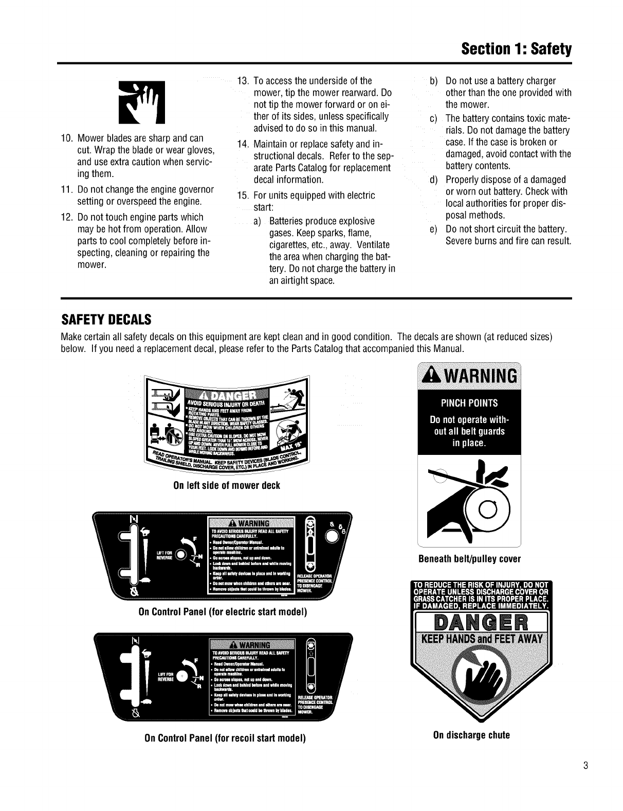
SAFETYDECALS
Makecertainall safetydecalsonthis equipmentare keptcleanandin good condition. The decalsareshown (at reducedsizes)
below. If you needa replacementdecal,pleasereferto the PartsCatalogthat accompaniedthis Manual.
On leftside ofmowerdeck
OnControlPanel (for electricstartmodel)
Beneathbelt/pulleycover
On ControlPanel (for recoilstartmodel)
DANQER
Ondischargechute
Assembly
ASSEMBLYSTEPS
To preventpersonal injury or property
damage, do not attempt to start the
engine until all assembly steps are
complete and you have read and
understand the safety, controls and
operatinginstructionsinthismanual.
INTRODUCTION
Pleasecarefullyfollow theseassembly
steps to properly prepareyour machine
for use. We recommendthat you read
this Sectionin its entirety beforebegin-
ningassembly.
STEP1: Unpacking Mower
NOTE:LEFTand RIGHTsides of the unit
areas viewedfrom the operator'sposi-
tion behindthe handlebars.
1. Cutstraps, if present,securingunit
to pallet. Leaveunit on pallet during as-
sembly (to safelyremoveunit from pal-
let, wait until you havecompletedas-
sembly steps 1-4).
2. Removeany protectivepackaging
from aroundthe handlebars.Cutthe
plastic tie straps holdingthe control rods
and struts to the handlebars.
NOTE:All referencesto left, right,front
and rearof the machineare determined
by standingbehindthe handlebarsand
facingthe direction of forward travel.
INSPECTIONAFTERDELIVERY
Inspectthe shipping crateand machine
immediatelyafterdelivery. Makesure
neitherthe carton/cratenor the contents
havebeendamaged.
If you find or suspectany damage,con-
tact the carrier (trucking company)
immediately. Inform them of the specific
damageandthatyou wish to file a claim.
To protectyour rights, besure to put
this in writing to the carrier within 15
days. Thecarrier will let you knowhow
to proceedwith your claim. Pleaselet us
knowif you needany assistance.
STEP2: Attach Handlebars
to Engine Deck
NOTE:Fourscrews(D, Figure2-2) are
usedto connect the handlebarsto the
enginedeck. At the factory, two of these
screws (front) arethreadeddirectly into
lock nuts weldedto the backsidesof the
deck.The remainingtwo screws (rear)
securethe lower handleto the deck.
1. Removeandsavethe two 5/16"-18 x
3/4"screws (front) mentionedin the
NOTEabove.
2. Loosen,but do NOTremove,the two
5/16"-18 x 3/4" screws(rear). Leavethe
cardboardinsertfound betweenthe left-
hand handlebarandenginedeck,in
place.
3. Carefullypivot the handlebarsover
•Wire Cutter
• Two7/16" Wrenches
• 3/8" Wrench
• 1/2" Wrench
• Scissorsor PenKnife
the engineandpositionthe handlebar
TOOLS/MATERIALSNEEDED: ends (E, Figure2-2) againstthe sides of
the enginedeck. Do not alloow the han-
dlebarsto rubagainstthe enginewhile
pivoting them.
4. Looselysecurethe right-hand handle-
barendto the deck by reinsertingthe
screw (D, Figure2-2) removedearlier.
• Needle-nosePliers Donot securethe left-handhandleat
• Tire Gauge this point in assembly.
5. Removethe cardboardinsertfrom
betweenthe left-handhandlebarand
enginedeck
8. Removethe nut from the lower screw
(B, Figure2-1) which securesthe con-
sole to the handlebaron the left-hand
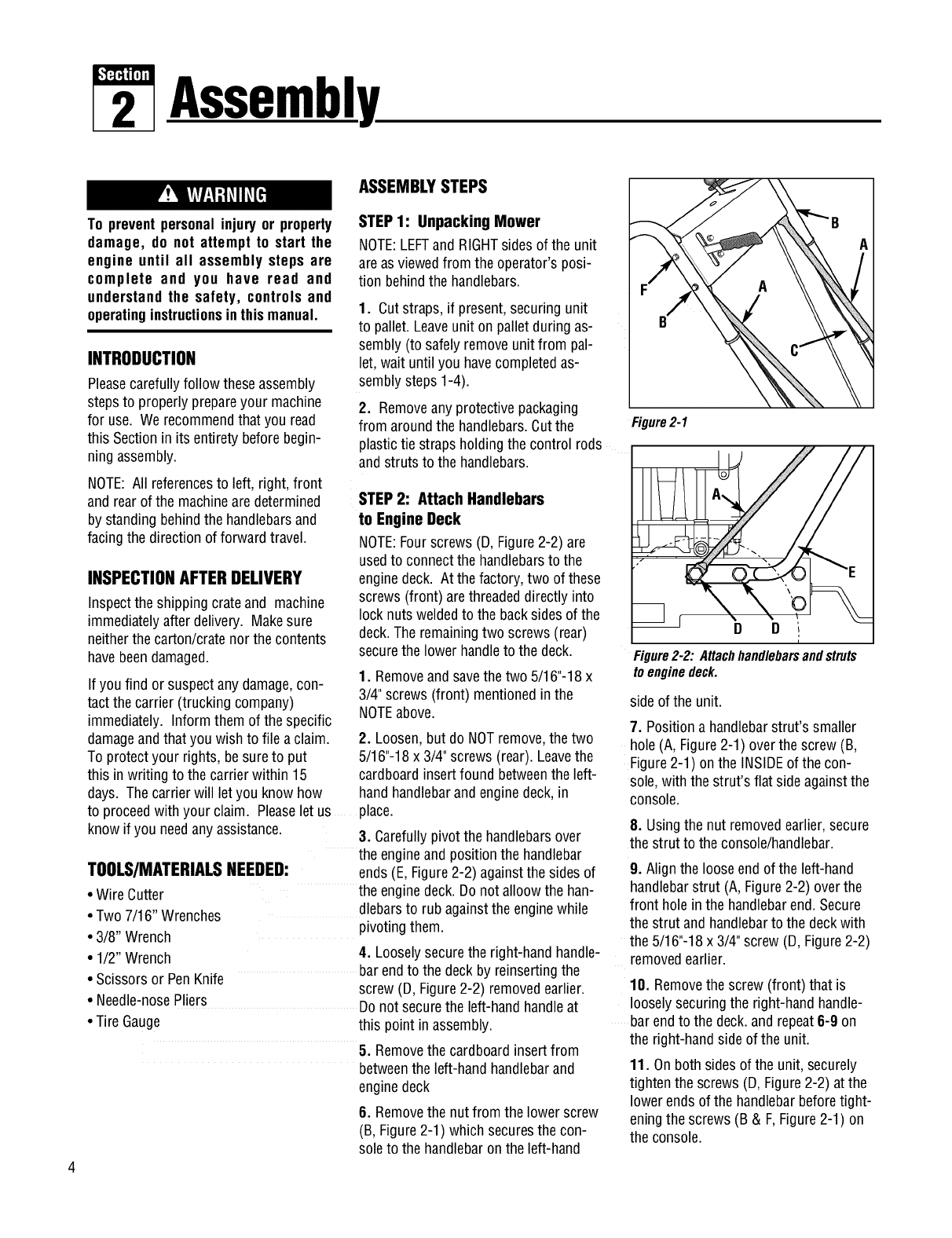
Figure2-1
D D ,
i
Figure2-2: Attachhandlebarsandstruts
toenginedeck.
side of the unit.
7. Positiona handlebarstrut's smaller
hole (A, Figure2-1) over the screw (B,
Figure 2-1) on the INSIDEof the con-
sole,with the strut's flat side againstthe
console.
8. Usingthe nut removedearlier,secure
the strut to the console/handlebar.
9. Align the loose endof the left-hand
handlebarstrut (A, Figure2-2) over the
front holein the handlebarend. Secure
the strut and handlebarto the deckwith
the 5/16"-18 x 3/4" screw (D, Figure2-2)
removedearlier.
10. Removethe screw (front) that is
looselysecuringthe right-handhandle-
barendto the deck.and repeat6-9 on
the right-handside of the unit.
11. On both sidesof the unit, securely
tightenthe screws(D, Figure2-2) at the
lower ends of the handlebarbeforetight-
eningthe screws (B & F, Figure2-1) on
the console.
Section2: Assembly
STEP 3 ATTACHINGTHEBATTERY
CABLES(MODEL F753B)
Thepositive batteryterminal is marked
Pos.(+). The negativebatteryterminal is
markedNeg.(-).
The moweris shipped with the positive
(Red) cablesecuredto the positiveter-
minal (+) onthe battery.Attachthe
ground (Black)cableto the negativeter-
minal (-) onthe battery,asfollows:
1. Removethe plastic battery cover (G,
Figure.2-3) by unthreadingthe two wing
nuts (H, Figure. 2-3) which secure it to
the batteryhold-down rods (I, Figure.2-
3)
2. Remove the hex bolt and hex nut
from the groundcable/heavyblackwire
(E, Figure.2-3).
3. Securethe ground cableto the nega-
tive batteryterminal (-) with the bolt and
hex nut just removed.
IMPORTANT:
•If the batteryis put into serviceafter
the dateshown ontop of battery,
chargethe batteryas instructedin the
Maintenencesectionof this manual
prior to operatingthe tiller.
STEP 4: Attach Control Rods
A. AttachWheel DriveControlRod
1. Locatethe wheel drivecontrol rod (F,
Figures2-4A & 2-7) and removethe an-
gledendfrom the left handlebarby re-
movingthe hairpinclip whichsecuresit
to the Wheel DriveControllever (V,
Figure2-4A)
2. At left side of enginedeck, insert
swivel block (H,Figures2-4 & 2-5) on
wheeldrive control rod into wheeldrive
control arm (U, Figure2-4).
3. Adda5/16"washer(A, Figure2-4)
andsecurewith a hairpinclip (B).
4. At upperend of control rod, re-insert
the angledend into the Wheel Drive
Controllever (V, Figure2-4A) and re-
attach with hairpinclip (BB) removed
earlier.
B.AttachOperatorPresenceControl
Rod
1. Locatethe OperatorPresenceControl
rod (E, Figures.2-4 and 2-5). At bottom
of control rod, insert swivel block (G,
Figures2-4 & 2-5) into control arm (T,
Figure2-4).
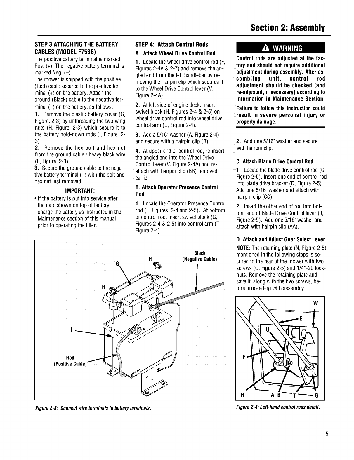
HBlack
(NegativeCable)
H
Red /
(PositiveCable)
Figure2-3: Connectwireterminalsto batteryterminals.
Controlrodsare adjusted at the fac-
tory andshouldnot requireadditional
adjustmentduringassembly.Afteras-
sembling unit, control rod
adjustment should be checked (and
re-adjusted,if necessary)accordingto
information in Maintenance Section.
Failureto follow this instructioncould
result in severe personal injury or
propertydamage.
2. Add one5/16"washerand secure
with hairpinclip.
C.AttachBladeDriveControlRod
1. Locatethe bladedrive control rod (C,
Figure2-5). Insert oneendof control rod
into bladedrive bracket (D,Figure2-5).
Add one5/16"washerandattachwith
hairpinclip (CC).
2. Insertthe other endof rod into bot-
tom endof BladeDriveControl lever(J,
Figure2-5). Add one5/16"washerand
attach with hairpin clip (AA).
D. AttachandAdjustGearSelectLever
NOTE:The retainingplate (N,Figure2-5)
mentionedin the following steps is se-
cured to the rearofthe mowerwith two
screws (O, Figure2-5) and1/4"-20 lock-
nuts. Removethe retainingplateand
saveit, along with thetwo screws, be-
fore proceedingwith assembly.
W
H A,B _G
Figure2-4:Left-handcontrolrodsdetail.
Section2: Assembly
BB
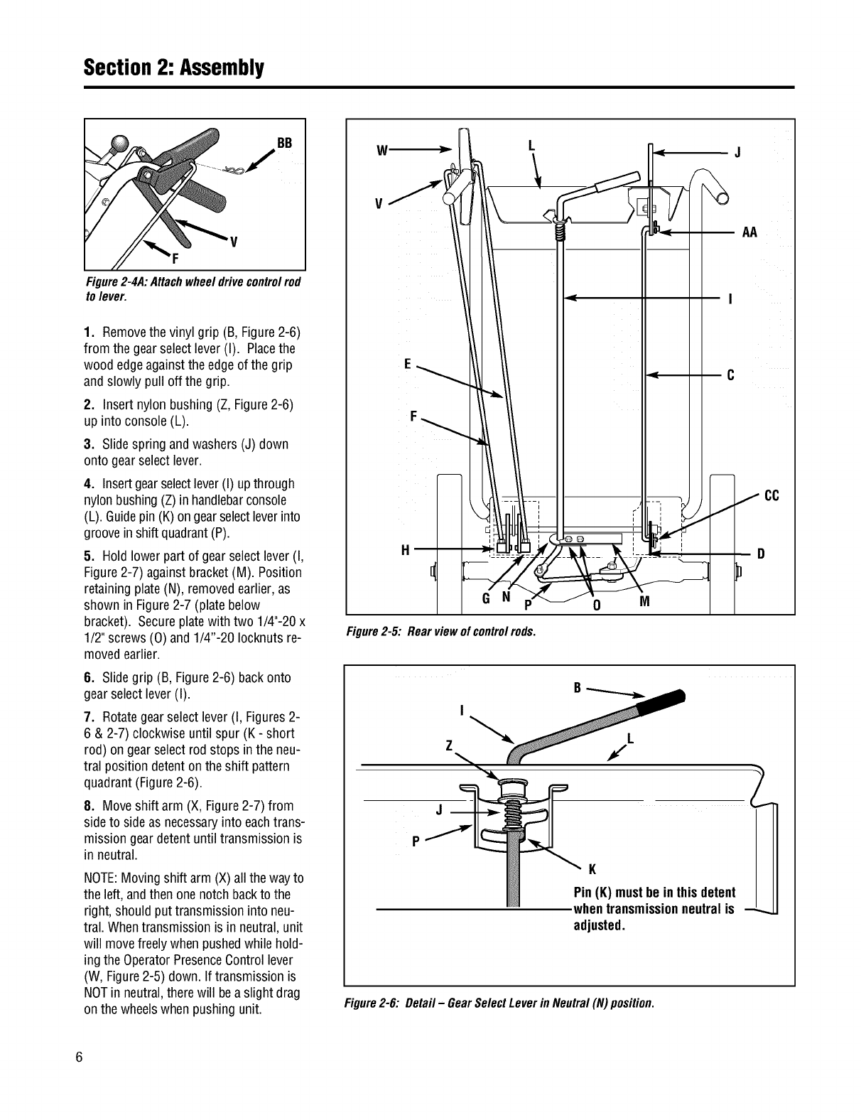
Figure2-4A:Attachwheeldrivecontrolrod
to lever.
1. Removethe vinyl grip (B, Figure2-6)
from the gearselect lever (I). Placethe
wood edgeagainstthe edgeof the grip
andslowly pull off the grip.
2. Insert nylon bushing(Z, Figure2-6)
up into console(L).
3. Slidespring andwashers (J) down
onto gearselect lever.
4. Insertgearselectlever(I) upthrough
nylon bushing(Z) in handlebarconsole
(L). Guidepin (K)ongearselectleverinto
grooveinshift quadrant(P).
5. Hold lower part of gearselect lever(I,
Figure2-7) againstbracket(M). Position
retaining plate(N), removedearlier, as
shown in Figure2-7 (plate below
bracket). Secureplatewith two 1/4"-20x
1/2" screws(0) and1/4"-20 Iocknuts re-
movedearlier.
6. Slidegrip (B, Figure2-6) backonto
gearselectlever (I).
7. Rotategearselect lever (I, Figures2-
6 & 2-7) clockwise until spur (K - short
rod) ongearselect rod stops in the neu-
tral position detenton the shift pattern
quadrant(Figure2-6).
8. Moveshift arm (X, Figure2-7) from
side to sideas necessaryinto eachtrans-
mission geardetentuntil transmissionis
in neutral.
NOTE:Movingshift arm (X) allthe wayto
the left, andthen onenotch backto the
right, should put transmissioninto neu-
tral. Whentransmission is in neutral,unit
will movefreely whenpushedwhile hold-
ingthe OperatorPresenceControllever
(W, Figure2-5) down.If transmissionis
NOTin neutral,therewill beaslight drag
on the wheelswhen pushingunit.
WJ
V
F
G N
Figure2-5: Rearviewofcontrolrods.
0M
C
f2
K
Pin(K) mustbe inthisdetent
whentransmissionneutralis --_
adjusted.
Figure2-6: Detail -GearSelectLeverin Neutral(N) position.
6
Section2: Assembly
9. Whenshift arm (X)is in neutralposi-
tion, rotateshift link (P)toward endof
gearselectlever rod (I). Adjustlength
of shift link (P) as necessaryto fit into
hole in bottom of gearselectlever (I).
NOTE:Pin (K) on GearSelectLever(I)
must beheld inthe neutralposition
detentonthe shift quadrant(see Figure
2-6) while shift link (P, Figure2-7) is
adjusted.
10. Insert hookedendof shift link (P,
Figure2-7) into holein bottom end of
gearselectlever (I) andsecurewith
hairpinclip (Q).
NOTE:It may benecessaryto lift gear
selectlever (I) to install shift link (P).
11. Removeunit from shipping crate.
To remove,hold down Operator
PresenceControllever (W, Figure2-5)
which releasesthe wheel brake.
12. With unit on levelground, hold
down OperatorPresenceControllever
(W, Figure2-5) and push unit forward
and backward.Thewheelsshould move
freely. If not, adjust length of shift link
(P, Figure2-7) as necessary.
13. Putthe GearSelectLeverin neutral
(N), releaseall of the control leversand
try to push the unit forward and back-
ward. The wheelsshould not turn. If
they doturn, an adjustmentis neces-
sary. DONOTOPERATETHEUNIT
UNTILTHEWHEELBRAKEMECHANISM
HASBEENADJUSTEDAND ISWORK-
INGPROPERLY.See"WheelBrake
Adjustment"in Section5 "Maintenance."
STEP5: Secure Wire Harness
1. At the unattachedendof theelectrical
wire harness,therearefour wires at-
tachedto a largeplastic connectorand
two wires attachedto a small plastic
connector.. Plugthe largeconnector
into the bottom of the ignition keyswitch
that is locatedon the undersideof the
handlebarconsole(not pictured).
3. Usetwo cableties to securethe wire
STEP 6: Check Motor Oil Level
1. Movemowerto a levelarea.Press
and hold OperatorPresenceControl
lever (W,Figure2-5) to movemower.
2. The moweris shippedwith oil in the
engine. However,you MUSTcheckthe
oil levelaccordingto the instructionspro-
vided inthe separateEngineOwner's
Manualincludedinthe unit'sliterature
packagebeforestartingthe mower.
Do not use the mower if the wheels
continue to turn after releasing the
Operator Presence Control and the
Wheel DriveControl.
Severe personal injury or property
damagecouldresult if this instruction
is notfollowed.
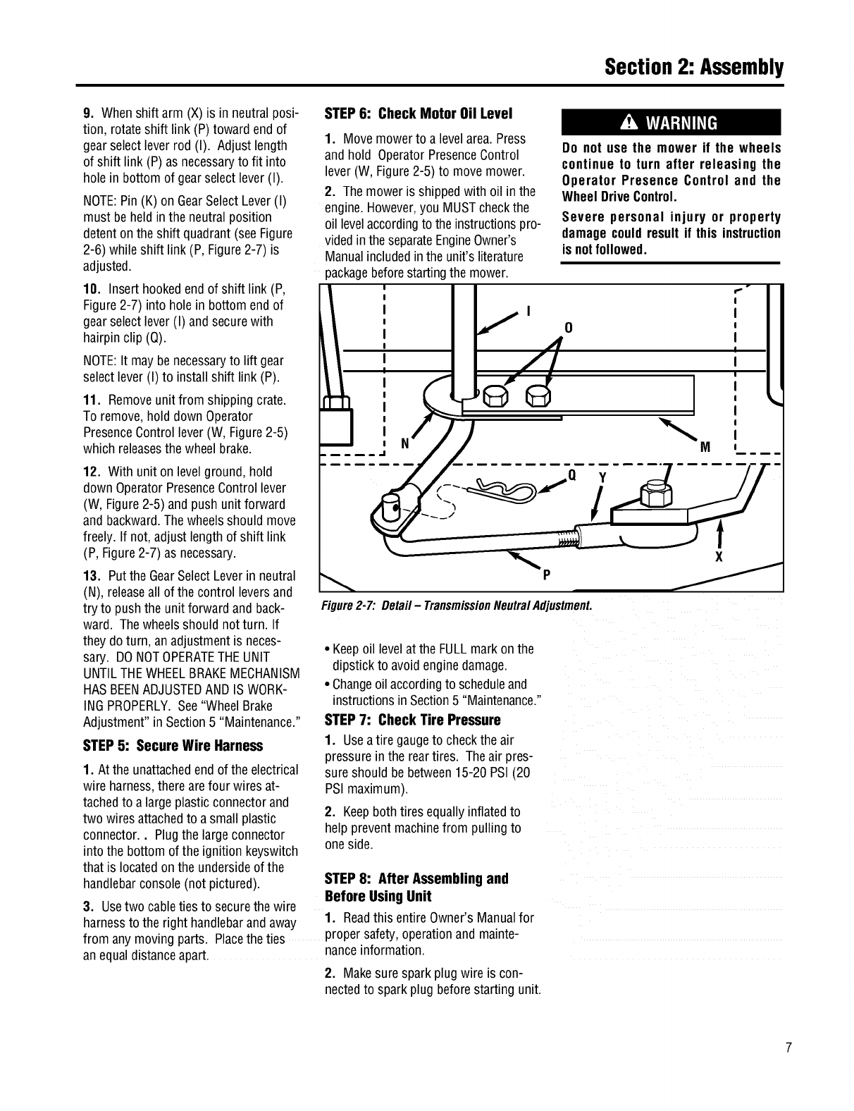
I f o
Figure2-7: Detail- TransmissionNeutralAdjustment.
• Keepoil levelat the FULLmarkon the
dipstick to avoidenginedamage.
• Changeoil accordingto scheduleand
instructionsin Section5 "Maintenance."
STEP 7: Check Tire Pressure
1. Useatire gaugeto checkthe air
pressurein the reartires. The air pres-
sure should bebetween15-20 PSI (20
PSI maximum).
2. Keepboth tires equallyinflatedto
helppreventmachinefrom pullingto
oneside.
STEP 8: After Assemblingand
Before UsingUnit
1. Readthis entire Owner's Manualfor
harnessto the right handlebarandaway o.
from any movingparts. Placethe ties propersaTety,operationand mainte-
anequaldistanceapart, nanceinformation.
2. Makesure sparkplug wire is con-
nectedto sparkplug beforestarting unit.
FeaturesandControls
Before operating mower, be sure to
read all safety, controlsand operating
instructions in this Manual and on
decalslocatedonmachine.
Severe personal injury or property
damage couldresult it this instruction
is notfollowed.
IMPORTANT: THE MOWER IS
EQUIPPED WITH A BLADE-BRAKE-
CLUTCHCONTROLSYSTEMWHICH IS
DESIGNED TO STOP THE MOWER
BLADESWITHIN THREE(3) SECONDS
AFTER RELEASEOF THE OPERATOR
PRESENCECONTROL. THIS SYSTEM
WILL STOPTHEBLADESBUTNOTTHE
ENGINE.THEREFORE,YOUCANDISEN-
GAGETHE BLADEDRIVEAT ANYTIME
WITHOUT HAVING TO STOP AND
RESTARTTHEENGINE.THIS FEATURE
IS PARTICULARLYUSEFULWHENYOU
NEEDTO CROSSGRAVELDRIVES OR
ROUGH TERRAIN AND YOU DO NOT
WANT THE SPINNING BLADES
TO STRIKE STONES OR HIDDEN
OBSTACLES.
MOWERFEATURESAND
CONTROLS
This sectiondescribesthe various
featuresand controls on the unit. Refer
to the next section "Operation"for
detailedoperatinginstructions. Also,
readthe separateEngineOwner's
Manualfor a detailedexplanationof the
proper useof the enginecontrols.
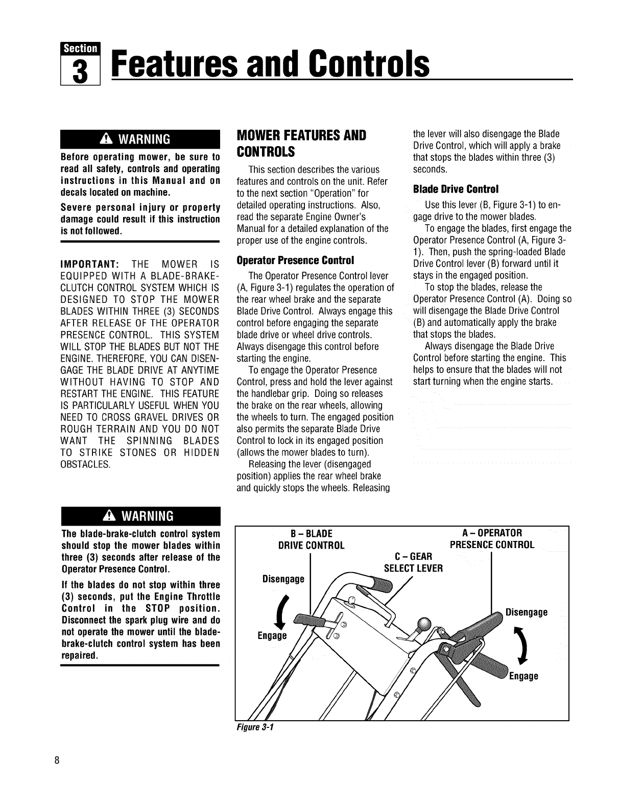
Operator Presence Control
The OperatorPresenceControllever
(A, Figure3-1) regulatesthe operationof
the rearwheel brakeandthe separate
BladeDriveControl. Alwaysengagethis
control beforeengagingthe separate
bladedrive or wheeldrive controls.
Always disengagethis control before
starting the engine.
To engagethe OperatorPresence
Control,pressand holdthe leveragainst
the handlebargrip. Doingso releases
the brakeon the rearwheels,allowing
the wheelsto turn. The engagedposition
also permits the separateBladeDrive
Controlto lock in its engagedposition
(allowsthe mowerbladesto turn).
Releasingthe lever (disengaged
position) appliesthe rearwheel brake
andquickly stops the wheels. Releasing
the leverwill also disengagethe Blade
DriveControl,which will apply a brake
that stops the bladeswithinthree (3)
seconds.
Blade Drive Control
Usethis lever (B, Figure3-1) to en-
gagedrive to the mower blades.
To engagethe blades,first engagethe
OperatorPresenceControl (A, Figure3-
1). Then,push the spring-loadedBlade
DriveControllever (B)forward until it
stays in the engagedposition.
To stop the blades,releasethe
OperatorPresenceControl (A). Doingso
will disengagethe BladeDriveControl
(B) andautomaticallyapply the brake
that stops the blades.
Alwaysdisengagethe BladeDrive
Controlbeforestarting the engine. This
helpsto ensurethatthe bladeswill not
start turning whenthe enginestarts.
The blade-brake-clutchcontrolsystem
should stop the mower blades within
three (3) secondsafter release of the
OperatorPresenceControl.
If the blades do not stopwithin three
(3) seconds, put the Engine Throttle
Control in the STOP position.
Disconnectthe sparkplugwire and do
not operatethe moweruntil the blade-
brake-clutchcontrol systemhas been
repaired.
B- BLADE
DRIVECONTROL
Disengage
Engage
C- GEAR
SELECTLEVER
A-OPERATOR
PRESENCECONTROL
Disengage
Engage
Figure3-1
Section3: Featuresand Controls
Operating Symbols Varioussymbolsare usedon the mowerto indicatecontrol settings (your modelmay not haveall of the
symbols). Thesesymbolsareshown below with a descriptionof their meaning.
ENGINE ENGINE ENGINE
FAST SLOW CHOKE ENGAGE DISENGAGE STOP START RUN
Gear Select Lever
Usethis lever (C,Figure3-1) to select
any of four forward groundspeeds(1 -
Slow,2 and3 - Medium,4 - Fast),N
(Neutral)and R (Reverse).The gearshift
patternis shown in Figure3-2.
Toavoiddamagingthetransmis-
sion, donotshiftgearswhenthe
moweris moving.
Forforward travel, use oneof the four
numberedsettings. To select reverse,
shift to neutralandthen pull upon the
lever.Turn the leverto the R (reverse)
positionand releasethe lever.
Put the leverin N (neutral)to manu-
ally pushthe mowerand whenthe
moweris not in use.
PresenceControlalong with the Wheel
DriveControl.
Whenstarting the engine,the Wheel
DriveControlshould bedisengaged(re-
leased).This helpsto ensurethat the
wheelswill not start turning whenthe
enginestarts.
Do notengagethe Wheel DriveControl
without first engaging the Operator
Presence Control. Doing so could
result in wear or damageto the wheel
brakemechanism.
Figure3-2:
Shiftpattern
onconsole.
A - OPERATOR
PRESENCECONTROL
Disengage
Engage
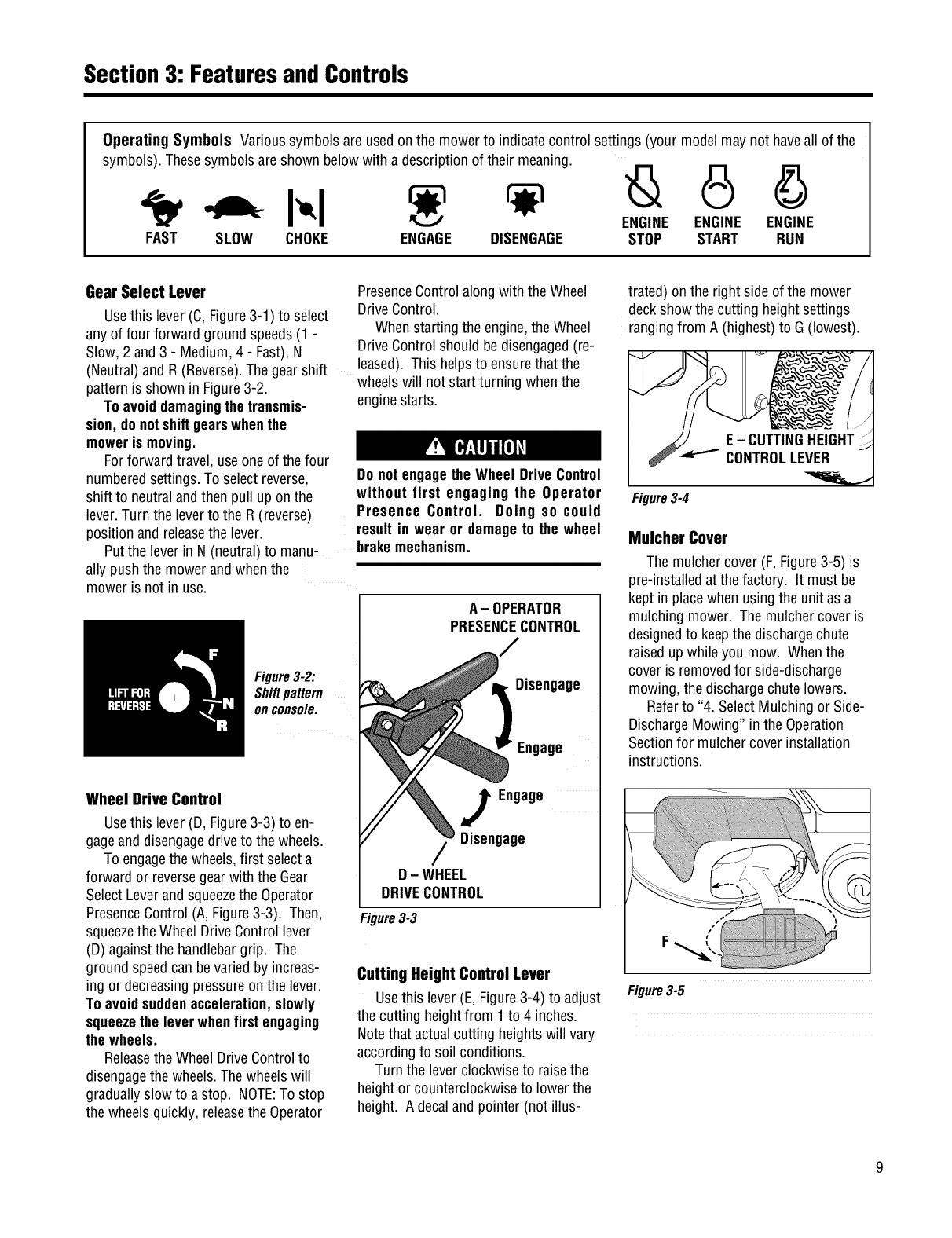
Wheel Drive Control
Usethis lever (D, Figure3-3) to en-
gageanddisengagedrive to the wheels.
To engagethe wheels,first selecta
forward or reversegearwith the Gear
SelectLeverandsqueezethe Operator
PresenceControl(A, Figure3-3). Then,
squeezethe Wheel DriveControllever
(D) againstthe handlebargrip. The
ground speedcan bevaried by increas-
ing or decreasingpressureon the lever.
Toavoidsuddenacceleration,slowly
squeezethe leverwhenfirstengaging
the wheels.
Releasethe WheelDriveControlto
disengagethe wheels.Thewheelswill
graduallyslow to a stop. NOTE:To stop
the wheelsquickly, releasethe Operator
JEngage
Disengage
D- WHEEL
DRIVECONTROL
Figure3-3
Cutting Height Control Lever
Usethis lever (E, Figure3-4) to adjust
the cutting heightfrom 1to 4 inches.
Notethat actualcutting heightswill vary
accordingto soil conditions.
Turnthe lever clockwiseto raisethe
heightor counterclockwiseto lowerthe
height. A decalandpointer (not illus-
trated) onthe right side of the mower
deckshow the cutting heightsettings
rangingfrom A (highest)to G (lowest).
Figure3-4
Mulcher Cover
The mulchercover (F,Figure3-5) is
pre-installedat the factory. It must be
kept in placewhen using the unit as a
mulchingmower. The mulchercoveris
designedto keepthe dischargechute
raisedupwhile you mow. Whenthe
cover is removedfor side-discharge
mowing,the dischargechutelowers.
Referto "4. SelectMulching or Side-
DischargeMowing" in the Operation
Sectionfor mulchercoverinstallation
instructions.
Figure3-5
Section3: FeaturesandControls
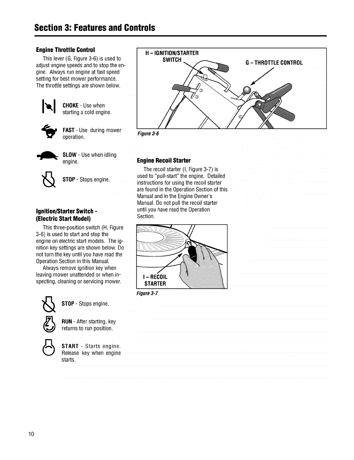
Engine Throttle Control
This lever(G, Figure3-6) is usedto
adjust enginespeedsandto stop the en-
gine. Always run engineat fast speed
setting for bestmower performance.
The throttle settings areshown below.
H - IGNITION/STARTER
SWITCH G- THROTTLECONTROL
J
I_1 CHOKE-Usewhen
starting a cold engine.
FAST- Use during mower
operation. Figure3-6
_._ SLOW- Usewhen idling
engine.
STOP- Stopsengine.
Ignition/Starter Switch -
(Electric Start Model)
Thisthree-position switch (H, Figure
3-6) is usedto start and stop the
engineon electric start models. Theig-
nition keysettings areshown below.Do
not turn the key until you havereadthe
OperationSectioninthis Manual.
Alwaysremoveignition keywhen
leavingmower unattendedor when n-
specting,cleaningor servicing mower.
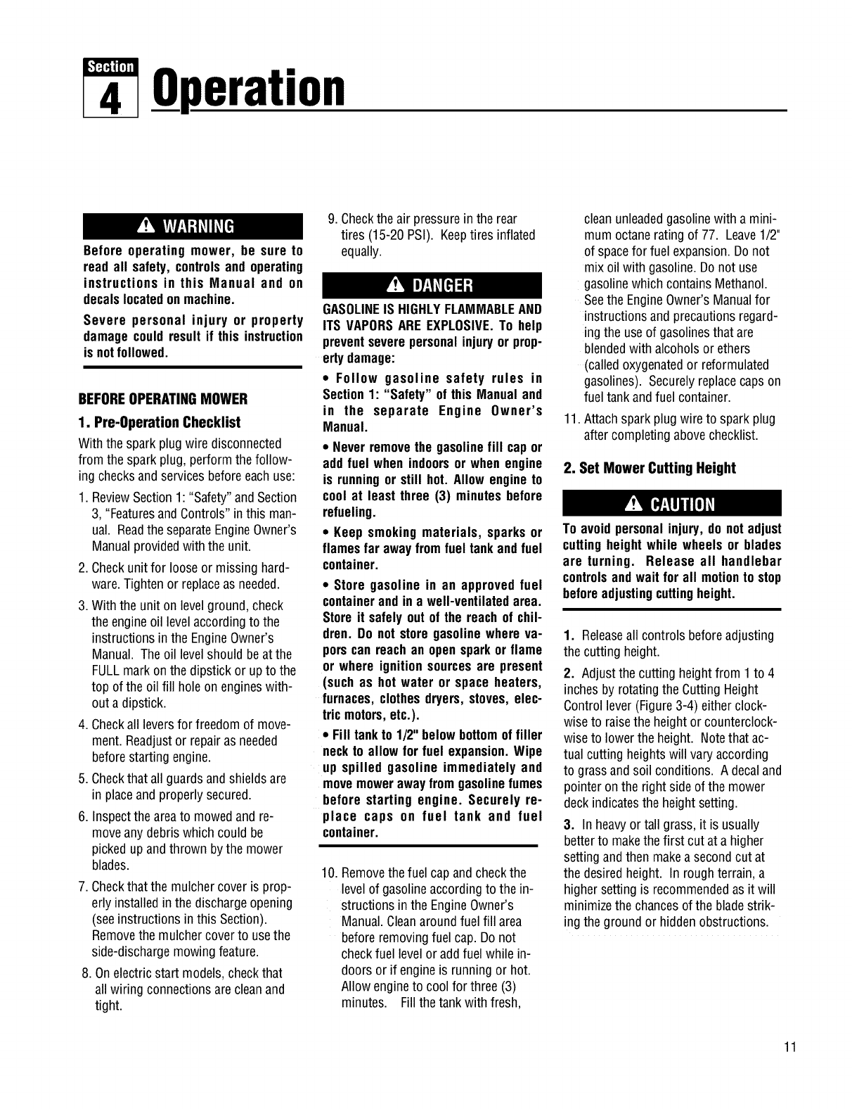
Engine Recoil Starter
The recoilstarter (I, Figure3-7) is
usedto "pull-start" the engine. Detailed
instructions for using the recoil starter
arefound in the OperationSectionof this
Manualand in the EngineOwner's
Manual.Do not pull the recoil starter
until you havereadthe Operation
Section.
I - RECOIL
STARTER
STOP- Stopsengine.
RUN- Afterstarting, key
returnsto run position.
Figure3-7
START - Starts engine.
Releasekey when engine
starts.
10
Operation
Before operating mower, be sure to
read all safety, controlsand operating
instructions in this Manual and on
decalslocatedonmachine.
Severe personal injury or property
damage couldresult if this instruction
is notfollowed.
BEFOREOPERATINGMOWER
1. Pre-OperaUon Checklist
With the sparkplug wire disconnected
from the spark plug, performthe follow-
ing checksandservicesbeforeeachuse:
1. ReviewSection1: "Safety"andSection
3, "FeaturesandControls"in this man-
ual. Readthe separateEngineOwner's
Manualprovidedwith the unit.
2. Checkunit for loose or missing hard-
ware.Tightenor replaceas needed.
3. With the unit on levelground, check
the engineoil level accordingto the
instructions in the EngineOwner's
Manual. Theoil levelshould beat the
FULLmarkonthe dipstick or up to the
top of the oil fill holeon engineswith-
out a dipstick.
4. Checkall leversfor freedomof move-
ment. Readjustor repairas needed
beforestarting engine.
5. Checkthat all guards andshieldsare
in placeand properly secured.
6. Inspectthe areato mowedandre-
moveany debris which could be
pickedup andthrown bythe mower
blades.
7. Checkthat the mulchercoveris prop-
erly installedin the dischargeopening
(seeinstructions in this Section).
Removethe mulchercoverto usethe
side-dischargemowingfeature.
8. Onelectric start models,checkthat
all wiring connectionsare cleanand
tight.
9. Checkthe air pressurein the rear
tires (15-20 PSI). Keeptires inflated
equally.
GASOLINEIS HIGHLYFLAMMABLEAND
ITS VAPORSAREEXPLOSIVE.To help
preventseverepersonalinjuryor prop-
ertydamage:
•Follow gasoline safety rules in
Section1: "Safety" of this Manualand
in the separate Engine Owner's
Manual.
•Neverremovethe gasolinefill cap or
add fuel when indoorsor when engine
is runningor still hot. Allow engineto
cool at least three (3) minutes before
refueling.
•Keep smokingmaterials, sparks or
flamesfar awayfromfuel tank andfuel
container.
•Store gasoline in an approved fuel
containerandin a well-ventilatedarea.
Storeit safely outof the reachof chil-
dren. Do notstore gasolinewhere va-
porscan reachan opensparkor flame
or where ignition sourcesare present
(suchas hot water or space heaters,
furnaces,clothesdryers, stoves,elec-
tric motors,etc.).
•Fill tankto 1/2" below bottomof filler
neckto allow for fuel expansion.Wipe
up spilled gasoline immediately and
movemowerawayfromgasolinefumes
before starting engine. Securely re-
place caps on fuel tank and fuel
container.
10. Removethe fuel cap andcheckthe
levelof gasolineaccordingto the in-
structions in the EngineOwner's
Manual.Cleanaroundfuel fill area
before removingfuel cap. Do not
checkfuel level or addfuel while in-
doors or if engineis running or hot.
Allow engineto cool for three (3)
minutes. Fill the tankwith fresh,
clean unleadedgasolinewith a mini-
mum octanerating of 77. Leave1/2"
of spacefor fuel expansion.Do not
mix oil with gasoline.Do not use
gasolinewhich contains Methanol.
Seethe EngineOwner's Manualfor
instructions and precautionsregard-
ingthe use of gasolinesthat are
blendedwith alcoholsor ethers
(calledoxygenatedor reformulated
gasolines). Securelyreplacecapson
fuel tankandfuel container.
11.Attach sparkplug wire to spark plug
after completingabovechecklist.
2. Set Mower Cutting Height
To avoid personalinjury, do notadjust
cuttingheightwhile wheels or blades
are turning. Release all handlebar
controlsandwait for all motionto stop
beforeadjustingcuttingheight.
1. Releaseall controls beforeadjusting
the cutting height.
2. Adjustthe cutting height from 1to 4
inchesby rotatingthe CuttingHeight
Controllever (Figure3-4) either clock-
wiseto raisethe height or counterclock-
wiseto lowerthe height. Notethat ac-
tual cutting heightswill vary according
to grassandsoil conditions. A decaland
pointer on the right side of the mower
deckindicatesthe height setting.
3. In heavyor tall grass, it is usually
betterto makethe first cut at a higher
setting andthen makeasecondcut at
the desiredheight. In roughterrain, a
highersetting is recommendedas it will
minimizethe chancesof the bladestrik-
ing the ground or hidden obstructions.
11
Section4: Operation
3. Test Blade-Brake-Clutch
Control System
Themower is equippedwith a blade-
brake-clutchwhich is designedto stop
the mowerbladeswithin three (3)
secondsafter releaseof the Operator
PresenceControlor the BladeDrive
Control. Nevertamperwith, or attempt
to defeatthe purposeof this safety
device.
Thecontrol system is a mechanical
devicewhich is subject to wear.
Therefore,test the operationof the
blade-brake-clutchcontrol system before
each useof the mower. Referto "Blade
BrakeControlTest"at the end of this
Section.
4. Select Mulching or Side-
Discharge Mowing
Before installingor removingmulching
cover, stop engine, wait for parts to
stopmoving,anddisconnectsparkplug
wire. Remove ignition key on electric
startmodels.
Youcan usethe mowereither as a
mulchingmoweror as aside-discharge
mower. To usethe mulchingfeature,in-
sert the mulchercover as described
below. Removethe mulchercoverto
side-dischargegrassclippings. The
mulchercover is designedto keepthe
dischargechute raisedup while mowing.
Whenthe cover is removed,the dis-
chargechutewill lower itself for side-
dischargemowing.
To install or removemulchercover:
1. Stop the engineand waitfor all parts
to stop moving. Disconnectthe spark
plug wire from the spark plug. Remove
the ignition keyon electric start models.
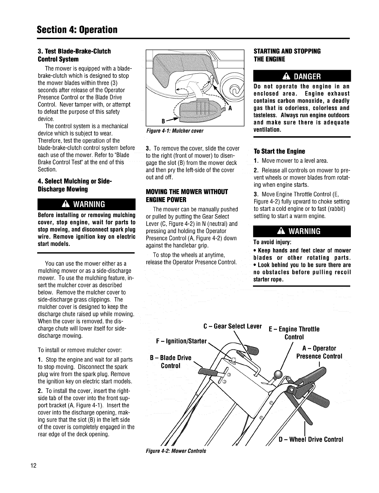
2. To installthe cover, insertthe right-
side tab of the coverinto the front sup-
port bracket(A, Figure4-1). Insertthe
cover into the dischargeopening, mak-
ing sure that the slot (B) in the left side
of the cover is completelyengagedin the
rearedgeof the deckopening.
B
Figure4-1:Mulchercover
STARTINGANDSTOPPING
THEENGINE
Do not operate the engine in an
enclosed area. Engine exhaust
containscarbon monoxide, a deadly
gas that is odorless, colorless and
tasteless. Alwaysrunengineoutdoors
and make sure there is adequate
ventilation.
3. To removethe cover, slide the cover
to the right (front of mower)to disen-
gagethe slot (B) from the mowerdeck
andthenprythe left-sideofthe cover
out andoff.
MOVINGTHEMOWERWITHOUT
ENGINEPOWER
The mowercan bemanuallypushed
or pulledby putting the GearSelect
Lever(C,Figure4-2) in N (neutral)and
pressingandholdingthe Operator
PresenceControl(A, Figure4-2) down
againstthe handlebargrip.
To stopthe wheelsat anytime.
releasethe OperatorPresenceControl.
ToStart the Engine
1. Movemowerto a levelarea.
2. Releaseall controls on mowerto pre-
ventwheelsor mower bladesfrom rotat-
ing when enginestarts.
3. MoveEngineThrottle Control(E,
Figure4-2) fully upwardto chokesetting
to start a cold engineor to fast (rabbit)
settingto start a warmengine.
Toavoidinjury:
• Keephandsand feet clear of mower
blades or other rotating parts.
•Lookbehindyouto be surethereare
no obstacles before pulling recoil
starterrope.
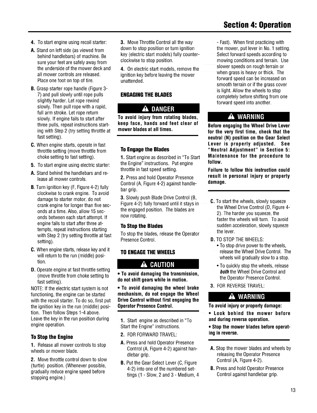
F-Ig
B - Blade Drive
Control
C - Gear Select Lever E - Engine Throttle
Control
A-Operator
Presence Control
I
Figure4-2: MowerControls
D - Wheel Drive Control
12
Section4: Operation
4. To start engineusing recoil starter:
A. Standon left side (as viewedfrom
behindhandlebars)of machine.Be
sure your feet aresafelyawayfrom
the undersideof the mowerdeckand
all mowercontrols are released.
Placeonefoot ontop of tire.
B. Graspstarter ropehandle(Figure3-
7) andpull slowly until ropepulls
slightly harder. Let roperewind
slowly. Thenpull ropewith a rapid,
full arm stroke. Let ropereturn
slowly. If enginefails to start after
three pulls, repeatinstructions start-
ingwith Step2 (try setting throttle at
fast setting).
C. Whenenginestarts, operateinfast
throttle setting (movethrottle from
chokesetting to fast setting).
5. To start engineusing electricstarter:
A. Stand behindthe handlebarsand re-
leaseall mowercontrols.
B.Turn ignition key(F, Figure4-2) fully
clockwiseto crank engine. To avoid
damageto starter motor, do not
crank enginefor longerthan five sec-
ondsat atime. Also, allow 15sec-
onds betweeneachstart attempt. If
enginefails to start afterthree at-
tempts, repeatinstructions starting
with Step2 (try setting throttle at fast
setting).
C. Whenenginestarts, releasekeyandit
will returnto the run (middle) posi-
tion.
D. Operateengineat fast throttle setting
(movethrottle from chokesettingto
fast setting).
NOTE:Ifthe electricstart system is not
functioning,the enginecan bestarted
with the recoilstarter. To do so,first put
the ignition keyin the run (middle) posi-
tion. Thenfollow Steps1-4 above.
Leavethe key inthe run position during
engineoperation.
ToStop the Engine
1. Releaseall mowercontrols to stop
wheelsor mower blade.
2. Movethrottle control downto slow
(turtle) position. (Wheneverpossible,
graduallyreduceenginespeed before
stoppingengine.)
3. MoveThrottle Controlall the way
downto stop position orturn ignition
key(electricstart models)fully counter-
clockwise to stop position.
4. Onelectric start models,removethe
ignition key beforeleavingthe mower
unattended.
ENGAGINGTHE BLADES
- Fast). Whenfirst practicingwith
the mower, put lever in No.1 setting.
Selectforward speedsaccordingto
mowingconditions andterrain. Use
slower speedson roughterrain or
when grass is heavyor thick. The
forward speedcan beincreasedon
smooth terrain or if the grass cover
is light. Allow the wheelsto stop
completelybeforeshifting from one
forward speedinto another.
To avoid injury from rotating blades,
keep face, hands and feet clear of
mowerbladesat all times.
To Engage the Blades
1. Startengineas describedin "To Start
the Engine"instructions. Putengine
throttle in fast speedsetting.
2. Pressandhold OperatorPresence
Control(A, Figure4-2) againsthandle-
bargrip.
3. Slowly push BladeDriveControl(B,
Beforeengagingthe Wheel DriveLever
for the very first time, check that the
neutral(N) positionon the GearSelect
Lever is properly adjusted. See
"Neutral Adjustment" in Section 5:
Maintenance for the procedure to
follow.
Failure to follow this instructioncould
result in personal injury or property
damage.
Figure4-2) fully forward until it staysin C.
the engagedposition. The bladesare
now rotating.
To Stop the Blades
To stop the blades,releasethe Operator
PresenceControl.
TO ENGAGETHEWHEELS
•To avoiddamagingthe transmission,
donotshiftgearswhile in motion.
•To avoid damagingthe wheel brake
mechanism,do notengage the Wheel
DriveControlwithoutfirst engagingthe
OperatorPresenceControl.
1. Start engineas describedin "To
Startthe Engine"instructions.
2. FORFORWARDTRAVEL:
To start the wheels,slowly squeeze
the Wheel DriveControl(D, Figure4-
2). The harderyou squeeze,the
faster the wheelswill turn. To avoid
sudden acceleration,slowly squeeze
the lever.
D.TO STOPTHEWHEELS:
•To stopdrive powerto the wheels,
releasethe WheelDriveControl. The
wheelswill graduallyslowto astop.
• To quickly stop the wheels, release
boththe WheelDriveControland
the OperatorPresenceControl.
3. FORREVERSETRAVEL:
Toavoidinjuryorpropertydamage:
•Look behind the mower before
andduringreverseoperation.
•Stopthe mowerbladesbeforeeperat-
ing in reverse.
A. Pressand holdOperatorPresence
Control (A, Figure4-2) againsthan-
dlebargrip.
B. Putthe GearSelectLever(C,Figure
4-2) into one of the numberedset-
tings (1 - Slow,2 and3 - Medium,4
A. Stop the mowerbladesandwheelsby
releasingthe OperatorPresence
Control(A, Figure4-2).
B. Pressandhold OperatorPresence
Controlagainsthandlebargrip.
13
Section4: Operation
C.
O.
E,
Putthe GearSelectLever(C, Figure
4-2) in R (reverse)setting by first
movingleverto N (neutral). Then
pull lever up,turn it to R position,
and releaselever.
To start the wheels,slowly squeeze
Wheel DriveControl(D, Figure4-2).
To avoid suddenacceleration,slowly
squeezethe lever.
TO STOPTHEWHEELS:
• To stopdrive powerto the wheels,
releasethe WheelDriveControl. The
wheelswill graduallyslow to astop.
• To quickly stop the wheels,release
both the WheelDriveControland
the OperatorPresenceControl.
• Returnthe GearSelectLeverto the
N (neutral)position whenyou have
completedreverseoperation. Allow
the wheelsto stop completelybe-
fore shifting from R (reverse)into a
forward speed.
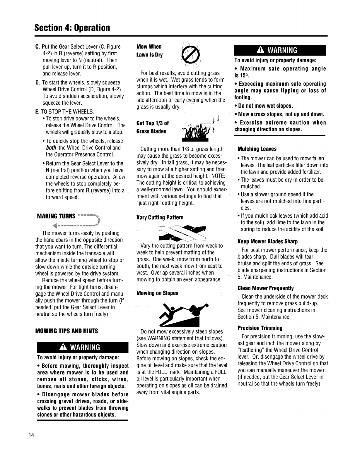
MowWhen
LawnIs Dry
For bestresults,avoid cutting grass
when it is wet. Wetgrasstendsto form
clumps which interferewith the cutting
action. The besttime to mow is in the
late afternoonor earlyeveningwhenthe
grassis usuallydry.
1
CutTop1/3 of /-_
GrassBlades __'
Cutting morethan 1/3 of grasslength
maycausethe grassto becomeexces-
sively dry. In tall grass,it maybeneces-
saryto mowat a highersetting andthen
mow againat the desiredheight. NOTE:
Thecutting height is critical to achieving
a well-groomedlawn. Youshould exper-
iment with varioussettingsto find that
"just right" cutting height.
MAKINGTURNS..... _ VaryCuttingPattern
The mowerturns easily by pushing
the handlebarsin the oppositedirection
that you wantto turn. Thedifferential
mechanisminside the transaxlewill
allow the inside turning wheelto stop or
slow down while the outsideturning
wheelis poweredby the drive system.
Reducethe wheel speedbeforeturn-
ing the mower. Fortight turns, disen-
gagethe WheelDriveControlandmanu-
Varythe cutting patternfrom weekto
weekto help preventmatting of the
grass. Oneweek, mowfrom north to
south, the nextweekmow from eastto
west. Overlapseveralincheswhen
mowingto obtainan evenappearance.
MowingonSlopes
ally push the mowerthrough the turn (if
needed,put the GearSelectLeverin
neutral so the wheelsturn freely).
MOWINGTIPSAND HINTS
Toavoidinjuryorpropertydamage:
•Before mowing, thoroughly inspect
area where mower is to be usedand
remove all stones, sticks, wires,
bones,nails andotherforeignobjects.
•Disengage mower blades before
crossinggravel drives, roads, or side-
walks to preventbladesfrom throwing
stonesor otherhazardousobjects.
Toavoidinjury orpropertydamage:
•Maximum safe operating angle
is 150.
• Exceedingmaximum safe operating
angle may cause tipping or loss of
footing.
• Donotmowwet slopes.
•Mowacrossslopes,notupanddown.
• Exercise extreme caution when
changingdirectiononslopes.
MulchingLeaves
• The mowercan beusedto mowfallen
leaves.Theleaf particlesfilter down into
the lawn andprovideaddedfertilizer.
• The leavesmust bedry in order to be
mulched.
• Usea slowerground speedif the
leavesarenot mulchedinto fine parti-
cles.
• If you mulch oakleaves(whichaddacid
to the soil), addlime to the lawn inthe
spring to reducethe acidity of the soil.
KeepMowerBladesSharp
For bestmowerperformance,keepthe
bladessharp. Dull bladeswill tear,
bruise andsplit the ends of grass. See
bladesharpeninginstructions in Section
5: Maintenance.
Do not mowexcessivelysteepslopes
(seeWARNINGstatementthat follows).
Slow down andexerciseextremecaution
whenchanging directionon slopes.
Beforemowing on slopes,checkthe en-
gine oil leveland makesure thatthe level
is at the FULLmark. Maintaininga FULL
oil levelis particularlyimportant when
operatingon slopesas oil can be drained
awayfrom vital engineparts.
CleanMowerFrequently
Cleanthe undersideof the mowerdeck
frequently to removegrass build-up.
Seemowercleaning instructionsin
Section5: Maintenance.
PrecisionTrimming
Forprecisiontrimming, usethe slow-
estgearand inch the mower alongby
"feathering"the WheelDriveControl
lever. Or, disengagethe wheeldrive by
releasingthe Wheel DriveControlso that
you can manuallymaneuverthe mower
(if needed,put the GearSelectLever in
neutralso that the wheelsturn freely).
14
Section4: Operation
BLADEBRAKECONTROLTEST
Whenthe OperatorPresenceControl
is releasedduring operationof the
mower, the enginedoesnot stop, but
the bladesshould stop within three (3)
seconds. The followingtest providesa
visualtest of whetherthe BladeBrake
ControlSystemis functioning. Perform
this test beforeeachuse of the mower.
1. Park moweron aportion of lawn
which has not beenrecentlymowed.
2. Setthe cutting height so the mower
cuts 1/3 of the grassheight.
To avoid personal injury or property
damage, make sure that the moweris
ongrass,andthatthe testarea is clear
of foreign objects and bystandersbe-
fore you beginthe Blade BrakeControl
Test.
If the OperatorPresenceControlor the
Blade Drive Controlare not adjusted
correctly, the blades may continueto
rotate after release of the Operator
PresenceControl. If the blades do not
stopwithinthree(3) secondsof release
ofthe OperatorPresenceControl,move
the EngineThrottleControlto the STOP
position, disconnect the spark plug
wire, andmovethe wire awayfromthe
sparkplug. Do not operatethe mower
until the Blade Brake ControlSystem
hasbeenrepaired.
Failure to do this couldresult in per-
sonal injuryor propertydamage.
3. Startthe engine.
4. Pressthe OperatorPresenceControl
down againstthe handlebargrip and
pushthe BladeDriveControlfully for-
ward until it staysin the engagedposi-
tion.
5. Putthe GearSelectLeverin the No.1
setting.
6. Engagethe wheelswith the Wheel
DriveControlanddrive the mowerfor
severalfeet. Then releasethe Operator
PresenceControl.
A. Look at the lawn just mowed.The
lawn should becut upto the point
wherethe OperatorPresenceControl
was released.
B. Pressthe OperatorPresenceControl
againstthe handlebargrip but DO
NOTre-engagethe BladeDrive
Control. Drivethe mowerforward
for severalmorefeet. Releasethe
OperatorPresenceControlandlook
at the lawn.The grassshould NOT
havebeencut. This indicatesthat
the OperatorPresenceControlhas
disengagedthe bladedrive and
stoppedthe blades.
7. If the mowercuts the grass in Step
6-B, the OperatorPresenceControlis
NOTdisengagingthe bladedrive.
Immediatelystopthe engine,discon-
nectthesparkplugwire, andmovethe
wireawayfromthesparkplug.
8. Do not use the mower until the Blade
BrakeControl Systemhas beenin-
spected,adjustedor repairedby an au-
thorized dealer.
15
Maintenance
Beforeinspecting,cleaningorservicingthemachine,shutoffengine,waitformovingpartstostop,disconnectspark
plugwireandmovewireawayfromsparkplug.Removeignitionkey(elecb'icstartmodels).
Failuretofollowtheseinstructionscanresultinseriouspersonalinjuryorpropertydamage.
Carefully read this Section on mower
and engine maintenance and service.
Performing the required maintenance
according to schedule will ensure the
proper performanceand long life of your
machine.
Beforeinspecting,cleaningor servicing
the machine, shut off engine, make
surethat all movingpartshavecometo
a completestop, disconnectsparkplug
wire and move wire away from spark
plug. Removeignition key on electric
startmodels.
Failureto followthese instructionscan
result in personal injury or property
damage.
NOTE: All referencesto left, right, front
and rearof the machinearedeterminedby
standingbehindthe handlebarsandfacing
the directionofforwardtravel.
IMPORTANT:REFERTO
MAINTENANCECHARTINTHIS
SECTIONFORA LISTINGOFREGU-
LARLYSCHEDULEDMAINTENANCE
PROCEDURES.
ENGINESERVICE
Routineengineserviceis described
below. Formore completeengineser-
vice information, referto the engine
manualprovidedwith your machine.
Forcompleteengineservice,contactan
authorizedenginedealer.
ENGINE OIL
OIL LEVEL:With moweron level
ground, the engineoil level must bebe-
tweenthe "ADD"and "FULL"marks on
the dipstickat all times. Checkbefore
each useandevery5 operatinghours.
OIL CHANGE:Ona newengine,change
oil afterfirst 2 hours of use,then change
oil regularlyas specifiedon the
MaintenanceChart. Referto Engine
Owner'sManualfor oil capacity.
OILTYPE:Useclean,high qualitydeter-
gent oil havinganA.P.I. serviceclassifi-
cation of SE,SFor SG. Useno special
additiveswith oil. Referto the Engine
Owner'sManualfor recommendedSAE
viscosity gradesthat matchthe starting
temperatureanticipatedbeforethe next
oil change.
CheckingOilLevel:
1. Park machineon levelground.
2. Stopengine, waitforpartstostop
moving,anddisconnectsparkplug
wire.
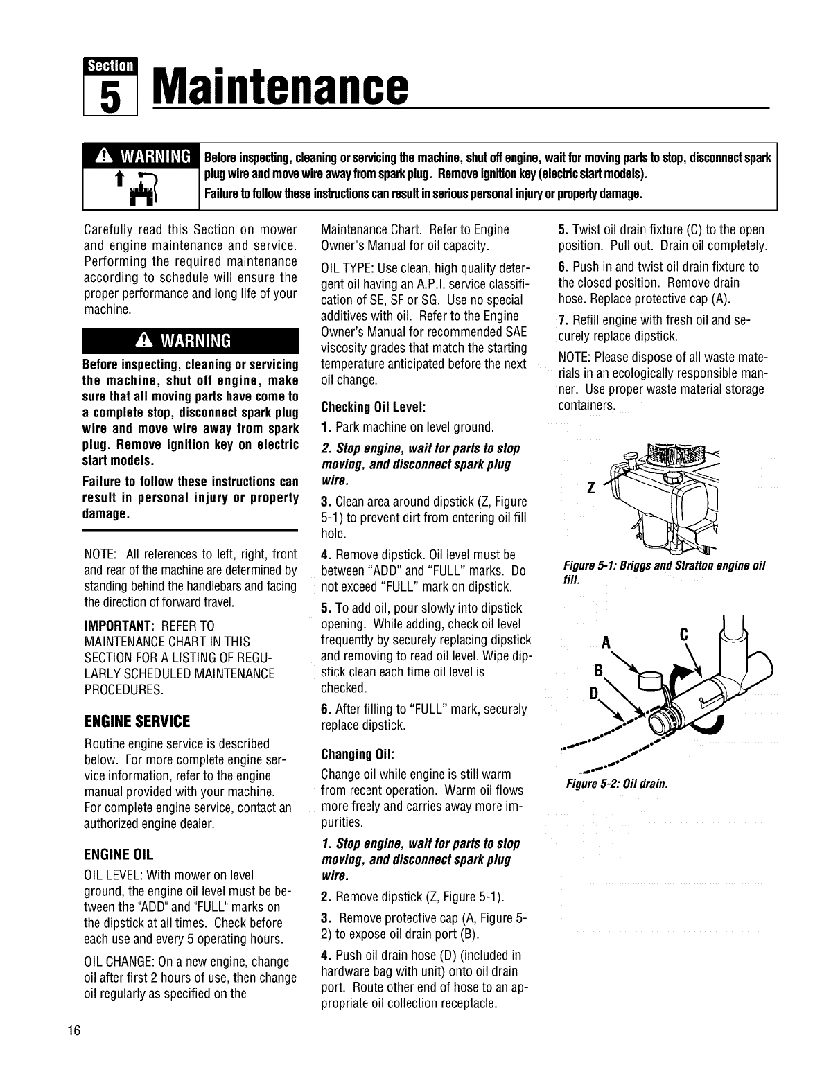
3. Cleanareaaround dipstick (Z,Figure
5-1) to preventdirt from entering oil fill
hole.
4. Removedipstick. Oillevel must be
between"ADD" and "FULL" marks. Do
not exceed"FULL" markon dipstick.
5. To addoil, pour slowly into dipstick
opening. While adding,check oil level
frequently by securely replacingdipstick
and removingto readoil level.Wipe dip-
stick cleaneachtime oil level is
checked.
6. Afterfilling to "FULL"mark, securely
replacedipstick.
ChangingOil:
Changeoil while engineis still warm
from recentoperation. Warm oil flows
morefreely andcarriesawaymore im-
purities.
1. Stopengine, waitforpartstostop
moving,anddisconnectsparkplug
wire.
2. Removedipstick (Z, Figure5-1).
3. Removeprotectivecap (A, Figure5-
2) to exposeoil drain port (B).
4. Push oil drain hose (D) (includedin
hardwarebagwith unit) onto oil drain
port. Routeother end of hose to anap-
propriateoil collection receptacle.
5. Twist oil drainfixture (C)to the open
position. Pullout. Drainoil completely.
6. Pushin andtwist oil drain fixture to
the closedposition. Removedrain
hose.Replaceprotectivecap (A).
7. Refillenginewith fresh oil andse-
curelyreplacedipstick.
NOTE:Pleasedisposeof all waste mate-
rials in an ecologicallyresponsibleman-
ner. Useproperwaste materialstorage
containers.
Figure5-1:BriggsandStrattonengineoil
fill.
Figure5-2:Oildrain.
16
Section5: Maintenance
W!_LW:I-'t_II_[_I Beforeinspecting,cleaningorservicingthemachine,shutoffengine,waitformovingpartstostop,disconnectspark
i1"_plugwireandmovewireawayfromsparkplug.Removeignitionkey(ele_icstartmodels).
MI Failuretofollowtheseinstructionscanresultinseriouspersonalinjuryorpropertydamage.
ENGINE CLEANING
• Stopengine, waitfor partsto stop
moving,disconnectsparkplugwire,
andallow engineto coolbeforein-
spectingorcleaningengine.
•Dailyor more often,before runningen-
gine, removegrassand chafffrom recoil
finger guardor rotatingscreento prevent
enginedamagecausedby overheating.
Also keepcooling vanes,governor link-
age,springsandcontrols free of debris.
•Dailyor more often, beforerunningen-
gine, cleanmuffler area(besure muffler
is cool) to removeall grassandcom-
bustibledebris. If engineis equipped
with a sparkarrestorscreen, removeas-
semblyevery50 hours for cleaningand
inspection.Replaceif damaged.
•Grassor chaff mayclog engine'sair
cooling system,especiallyafter pro-
longedoperationcutting tall, dry grass.
SeeEngineOwner's Manualfor instruc-
tions on cleaningunderneaththe engine
blower housing.
AIR CLEANERSERVICE
Improperair cleanermaintenancecan
causeenginedamage.Referto the
EngineOwner's Manualfor more com-
pleteair cleanerserviceinformation.
SERVICESCHEDULE:
Outerfoam pre-cleaner- washand re-oil
every25 operatinghours or everysea-
son, whicheveroccursfirst.
Innerpapercartridge- clean or replace
every100 operatinghours or everysea-
son, whicheveroccursfirst.
ToServiceAir Cleaner(Figure5-3):
1. Stopengine,wait for partsto stop
moving,anddisconnectsparkplug
wire.
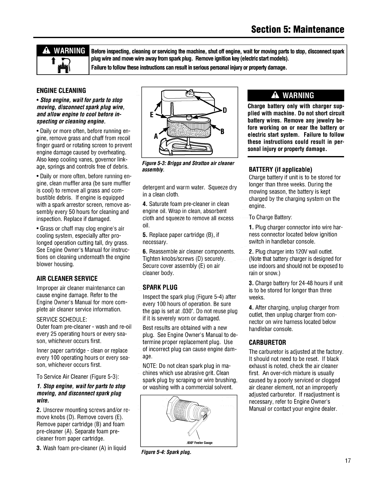
2. Unscrewmountingscrewsand/or re-
moveknobs (D). Removecovers (E).
Removepapercartridge(B) andfoam
pre-cleaner(A). Separatefoam pre-
cleanerfrom papercartridge.
3. Washfoam pre-cleaner(A) in liquid
A
Chargebattery only with chargersup-
pliedwith machine.Donotshortcircuit
batterywires. Removeany jewelry be-
fore working on or near the battery or
electricstart system. Failure to follow
these instructionscouldresult in per-
sonalinjuryorpropertydamage.
Figure5-3: BriggsandStrattonair cleaner
assembly.
detergentandwarm water. Squeezedry
in aclean cloth.
4. Saturatefoam pre-cleanerin clean
engineoil. Wrap in clean,absorbent
cloth andsqueezeto removeall excess
oil.
5. Replacepapercartridge(B), if
necessary.
6. Reassembleair cleanercomponents.
SPARKPLUG
Inspectthe sparkplug (Figure5-4) after
every 100hours of operation.Besure
the gapis setat .030".Do not reuseplug
if it is severelyworn or damaged.
Bestresultsare obtainedwith a new
plug. SeeEngineOwner'sManualto de-
termine proper replacementplug. Use
of incorrectplug can causeenginedam-
age.
NOTE:Do not cleanspark plug in ma-
chines which useabrasivegrit. Clean
spark plug by scrapingor wire brushing,
or washingwith a commercialsolvent.
BATTERY(if applicable)
Chargebatteryif unit is to bestoredfor
longerthan three weeks.Duringthe
mowingseason,the batteryis kept
chargedby the chargingsystem onthe
engine.
To ChargeBattery:
1. Plugchargerconnector into wire har-
nessconnector locatedbelow ignition
switch in handlebarconsole.
2. Plugchargerinto 120Vwall outlet.
Tightenknobs/screws(D) securely. (Notethat batterychargeris designedfor
Secure coverassembly(E)on air useindoorsandshouldnot beexposedto
cleaner body. rainorsnow.)
3. Chargebatteryfor 24-48 hours if unit
is to bestoredfor longerthan three
weeks.
.030' FeelerGauge
4. After charging,unplugchargerfrom
outlet, then unplugchargerfrom con-
nector on wire harnesslocatedbelow
handlebarconsole.
CARBURETOR
Thecarburetor is adjustedatthe factory.
It should not needto be reset. If black
exhaustis noted,checkthe air cleaner
first. An over-rich mixture is usually
causedby a poorly servicedor clogged
air cleanerelement,not an improperly
adjustedcarburetor. If readjustmentis
necessary,referto EngineOwner's
Manualor contactyour enginedealer.
Figure5-4: Sparkplug.
17
Section5: Maintenance
• !'T_TI-_I-'{_JI _[€']I Beforeinspecting,cleaningorservicingthemachine,shutoffengine,waitformovingpartstostop,disconnectspark
t_plugwireandmovewireawayfromsparkplug.Removeignitionkey(elecb'icstartmodels).
MI Failuretofollowtheseinstructionscanresultinseriouspersonalinjuryorpropertydamage.
ENGINESTORAGE The belt covermust be removedto per-
form severalmaintenanceprocedures.
If enginewill be unusedfor 30 daysor
more,prepareit for storage byfollowing To RemoveBelt Cover:
the recommendedproceduresfound in 1. Stopengine, wait forall partsto
the EngineOwner'sManual. stopmoving,anddisconnectspark
plug wire.
5. Loosenfour mounting bolts (L) se-
curing spindle housing (beneathmower
deck)to mowerdeck.
6. Slidespindle housing (with pulley at-
tached)towardcenter.
7. Replacebelt (N) with new belt.
MOWERSERVICE
The following maintenance/repairproce-
durescan be performedby eitherthe
owner or anauthorizedservicedealer.
Seeanauthorizedservicedealerfor
complete mowerservice.
TIPPING MOWER FOR SERVICE
and removecover.
To ReinstallBeltCover:
1. Positionbelt cover in place.
2. Securewith the four screwsremoved
earlier.
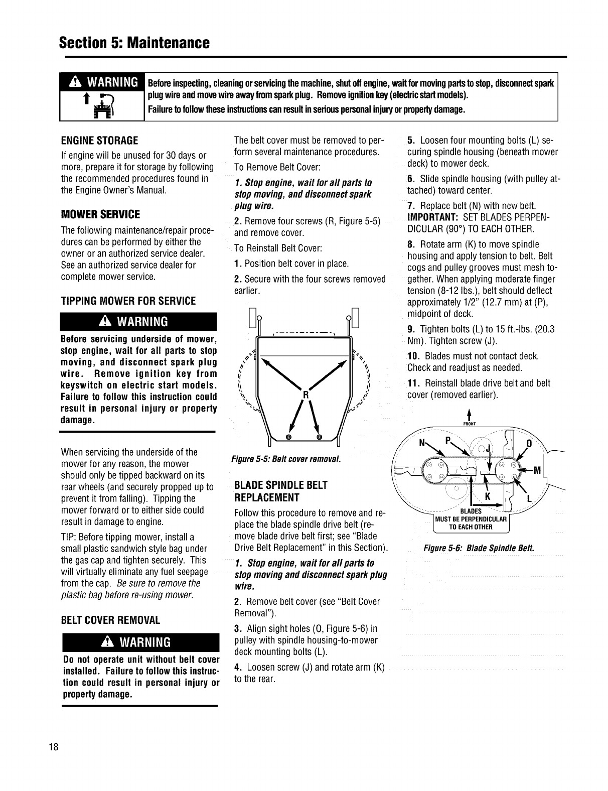
2. Removefour screws(R, Figure5-5) IMPORTANT:SETBLADESPERPEN-
DICULAR(90°) TO EACHOTHER.
8. Rotatearm (K)to movespindle
housing andapply tensionto belt. Belt
cogsand pulley groovesmust meshto-
gether.Whenapplying moderatefinger
tension (8-12 Ibs.),belt should deflect
approximately1/2" (12.7 mm) at (P),
midpointof deck.
Before servicing undersideof mower,
stop engine, wait for all parts to stop
moving, and disconnect spark plug
wire. Remove ignition key from
keyswifch on electric start models.
Failure to follow this instructioncould
result in personal injury or property
damage.
When servicingthe undersideof the
mowerfor any reason,the mower
should only betipped backwardon its
rearwheels(andsecurelyproppedupto
preventit from falling). Tipping the
mowerforward or to either side could
resultin damageto engine.
TIP: Beforetipping mower, installa
small plastic sandwichstyle bag under
the gascap andtighten securely. This
will virtually eliminateany fuel seepage
from the cap. Besure to removethe
plastic bagbefore re-usingmower.
BELTCOVERREMOVAL
Do not operate unit without belt cover
installed. Failureto followthisinstruc-
tion couldresult in personal injury or
propertydamage.
Figure5-5: Beltcoverremoval.
BLADESPINDLE BELT
REPLACEMENT
Followthis procedureto removeandre-
placethe bladespindle drive belt (re-
movebladedrive beltfirst; see "Blade
DriveBelt Replacement"inthis Section).
1. Stopengine,wait forall partsto
stopmovinganddisconnectsparkplug
wire.
9. Tightenbolts (L) to 15ft.-Ibs. (20.3
Nm).Tightenscrew (J).
10. Bladesmust not contact deck.
Checkand readjustas needed.
11. Reinstallbladedrive beltand belt
cover (removedearlier).
t
FRO_T
J
MUST BE PERPENDICULAR
TO EACH OTHER
Figure5-6: BladeSpindleBell
2. Removebelt cover(see "BeltCover
Removal").
3. Align sight holes (0, Figure5-6) in
pulleywith spindle housing-to-mower
deckmountingbolts (L).
4. Loosenscrew (J) and rotatearm (K)
to the rear.
18
Section5: Maintenance
W!_LY_TI:I-'t_II_[_IBeforeinspecting,cleaningorservicingthemachine,shutoffengine,waitformovingpartsto stop,disconnectspark
t _ plugwireandmovewireawayfromsparkplug.Removeignitionkey(elecb'icstartmodels).
Failuretofollowtheseinslxuctionscanresultinseriouspersonalinjuryorpropertydamage.
BLADEDRIVE BELT
REPLACEMENT
Followthis procedureto removeand re-
placethe bladedrive belt. Anassistant
will be needed.
To RemoveBelt:
1. Stopengine,wait for all partsto
stopmoving,anddisconnectspark
plugwire.
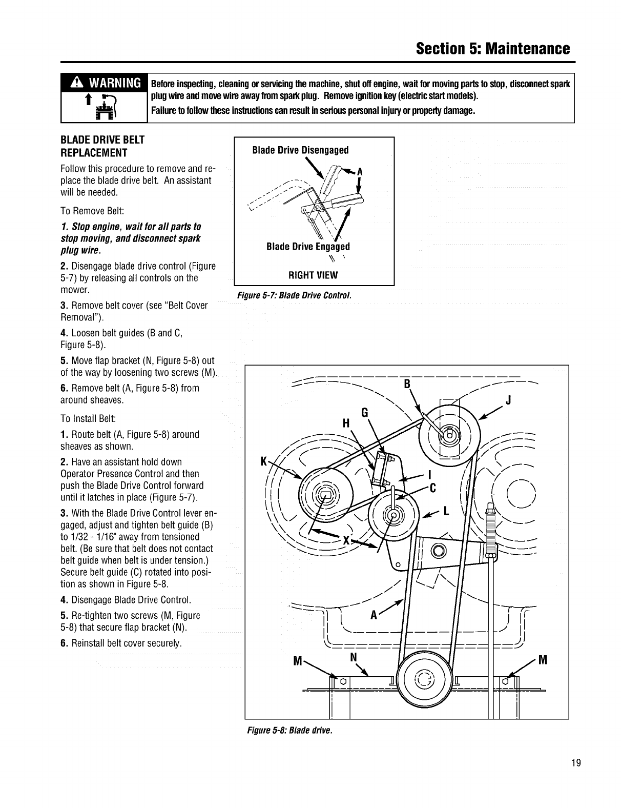
2. Disengagebladedrive control (Figure
5-7) by releasingall controls onthe
mower.
BladeDriveDisengaged
BladeDriveEngaged
\\
RIGHTVIEW
Figure5-7: BladeDriveControl
3. Removebelt cover (see"Belt Cover
Removal").
4. Loosenbelt guides (BandC,
Figure5-8).
5. Moveflap bracket(N, Figure5-8) out
of the way by looseningtwo screws (M).
8. Removebelt (A, Figure5-8) from
aroundsheaves.
To Install Belt:
1. Routebelt (A, Figure5-8) around
sheavesasshown.
2. Havean assistanthold down
OperatorPresenceControlandthen
push the BladeDriveControlforward
until it latchesin place(Figure5-7).
3. With the BladeDriveControlleveren-
gaged,adjustandtighten belt guide (B)
to 1/32- 1/16"awayfrom tensioned
belt. (Besurethat belt doesnot contact
belt guidewhen belt is undertension.)
Securebelt guide(C) rotatedinto posi-
tion as shownin Figure5-8.
4. DisengageBladeDriveControl.
5. Re-tightentwo screws (M, Figure
5-8) that secureflap bracket(N).
6. Reinstallbeltcover securely.
G\\
H
M
Figure5-8: Bladedrive.
19
Section5: Maintenance
W!_LY_II:I;t_II_[_I Beforeinspecting,cleaningorservicingthemachine,shutoffengine,waitformovingpartsto stop,disconnectspark
i_ _plugwireandmovewireawayfromsparkplug.Removeignitionkey(electricstartmodels).
Failuretofollowtheseinslxuctionscanresultinseriouspersonalinjuryorpropertydamage.
BLADEBRAKEREPLACEMENT
Followthis procedureto installa new
bladebrake.
To RemoveBladeBrake:
1. Stopengine,wait forall partsto
stopmoving,anddisconnectspark
plugwire.
2. Removebelt coveras describedin
"Belt CoverRemoval"instructions.
3. Removehardware(G, Figure5-8)
securingbladebrake(H).
4. Removeold brake(H) from idler
arm (I).
To Install Brake:
1. Positionnew brake(H) in placeon
idler arm (I).
2. Centerbrakein sheavegroove and
securebrake(H) with hardware(G) re-
movedearlier.
3. Reinstallbeltcover securely.
4. Test operationof bladebrake(see
"BladeBrakeControlTest" in Operation
section).
BLADEDRIVE BELT
ADJUSTMENT
Ifthe bladedrive belt is slipping dueto
lackof belt tension, follow the steps
below.
1. Stopengine,wait forall partsto
stopmoving,anddisconnectspark
plugwire.
2. Removebelt coveras describedin
"Belt CoverRemoval"instructions.
3. With moweron levelground, adjust
bladecutting height at about 3" (mea-
sure from ground to flat portion of
blade).
4. With the BladeDriveControl (Figure
5-7) inthe disengagedposition, set a
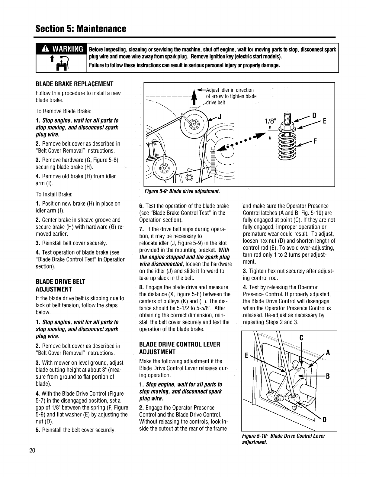
gapof 1/8" betweenthe spring (F,Figure
5-9) andflat washer(E)by adjustingthe
nut (g).
5. Reinstallthe belt coversecurely.
20
\
Adjust idlerin direction
of arrow to tighten blade
...drive belt
D
1/8" E
Figure5-9:Bladedriveadjustment.
6. Testthe operationof the bladebrake
(see"BladeBrakeControlTest" in the
Operationsection).
7. If the drive beltslips during opera-
tion, it may benecessaryto
relocateidler (J, Figure5-9) in the slot
providedin the mounting bracket.With
the enginestoppedandthesparkplug
wiredisconnected,loosen the hardware
onthe idler(J)and slide it forward to
take upslack inthe belt.
8. Engagethe bladedrive and measure
the distance(X, Figure5-8) betweenthe
centers of pulleys(K) and(L). Thedis-
tanceshould be5-1/2 to 5-5/8". After
obtainingthe correct dimension,rein-
stall the belt coversecurelyandtest the
operationof the bladebrake.
BLADEDRIVE CONTROLLEVER
ADJUSTMENT
Makethe following adjustmentif the
BladeDriveControlLever releasesdur-
ing operation.
1. Stopengine, waitforall partsto
stopmoving,anddisconnectspark
plug wire.
2. Engagethe OperatorPresence
Controlandthe BladeDriveControl.
Without releasingthe controls, look in-
side the cutout at the rearof the frame
and makesure the OperatorPresence
Controllatches (Aand B, Fig.5-10) are
fully engagedat point (C). If theyare not
fully engaged,improper operationor
prematurewearcould result. To adjust,
loosen hexnut (D) andshortenlength of
control rod (E).To avoid over-adjusting,
turn rod only 1 to 2 turns per adjust-
ment.
3. Tighten hexnut securelyafter adjust-
ing control rod.
4. Test by releasingthe Operator
PresenceControl. If properlyadjusted,
the BladeDriveControlwill disengage
when the OperatorPresenceControlis
released.Re-adjustas necessaryby
repeatingSteps2 and3.
C
E A
Figure5-10: BladeDriveControlLever
adjustment.
Section5: Maintenance
W!_LW:I-'t_II_[_I Beforeinspecting,cleaningorservicingthemachine,shutoffengine,waitformovingpartstostop,disconnectspark
t_plugwireandmovewireawayfromsparkplug.Removeignitionkey(ele_icstartmodels).
Failuretofollowtheseinstructionscanresultinseriouspersonalinjuryorpropertydamage.
WHEEL DRIVE BELT
REPLACEMENT
Followthis procedureto replacethe
wheeldrive belt.
1. Stopengine,wait forall partsto
stopmoving,anddisconnectspark
plugwire.
2. Releaseall mowercontrols.
3. Removebelt coveras describedin
"Belt CoverRemoval"instructions.
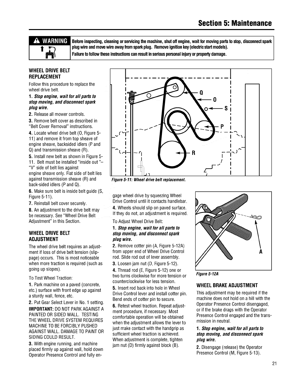
4. Locatewheeldrive belt (0, Figure5-
11) and removeit from top sheaveof
enginesheave,backsidedidlers (P and
Q)andtransmission sheave(R).
5. Install new belt as shownin Figure5-
11. Belt must be installed"inside out "-
"V" side of belt lies against
enginesheaveonly. Flatside of belt lies
againsttransmission sheave(R) and
back-sidedidlers (Pand Q).
6. Makesure belt is inside belt guide (S,
Figure5-11).
7. Reinstallbeltcover securely.
l
Figure5-11: Wheeldrivebeltreplacement.
gagewheel drive by squeezingWheel
DriveControluntil it contactshandlebar.
4. Wheelsshould slip on pavedsurface.
8. An adjustmentto the drive belt may
be necessary.See"Wheel DriveBelt If they do not, anadjustmentis required.
Adjustment"in this Section. To Adjust WheelDriveBelt:
1. Stopengine, waitforall partsto
stopmoving,anddisconnectspark
plug wire.
2. Removecotter pin (A, Figure5-12A)
from upperend of Wheel DriveControl
rod. Slide rod out of leverassembly.
3. Loosenjam nut (D, Figure5-12).
4. Threadrod (E, Figure5-12) oneor
two turns clockwisefor moretension or
counterclockwisefor lesstension.
5. Insert rod backinto hole in Wheel
DriveControlleverand installcotter pin.
Bendends of cotter pin to secure.
6. Retestwheeltraction. Repeatadjust-
mentprocedure,if necessary.Most
comfortableoperationwill beobtained
when the adjustmentallowsthe leverto
just makecontactwith the handgripas
sufficient wheeltraction is achieved.
When adjustmentis complete,tighten
jam nut (D) firmly againstblock (B).
WHEEL DRIVE BELT
ADJUSTMENT
Thewheel drive belt requiresanadjust-
ment if loss of drive belttension (slip-
page)occurs. This is most noticeable
when moretraction is required(suchas
going up slopes).
To TestWheelTraction:
1. Parkmachineon a paved(concrete,
etc.) surfacewith front edgeup against
a sturdy wall,fence, etc.
2. Put GearSelectLeverin No.1 setting.
IMPORTANT:DONOTPARKAGAINSTA
PAINTEDORSIDEDWALL. TESTING
THEWHEELDRIVESYSTEMREQUIRES
MACHINETO BEFORCIBLYPUSHED
AGAINSTWALL. DAMAGETO PAINTOR
SIDINGCOULDRESULT.
3. With enginerunning, and machine
placedfirmly up againstwall, hold down
OperatorPresenceControlandfully en-
A
Figure5-12A
WHEEL BRAKEADJUSTMENT
Thisadjustment mayberequiredif the
machinedoesnot hold on a hill with the
OperatorPresenceControldisengaged,
or if the brakedrags with the Operator
PresenceControlengagedandthe trans-
mission in neutral.
1. Stopengine, waitforall partsto
stopmoving,anddisconnectspark
plug wire.
2. Disengage(release)the Operator
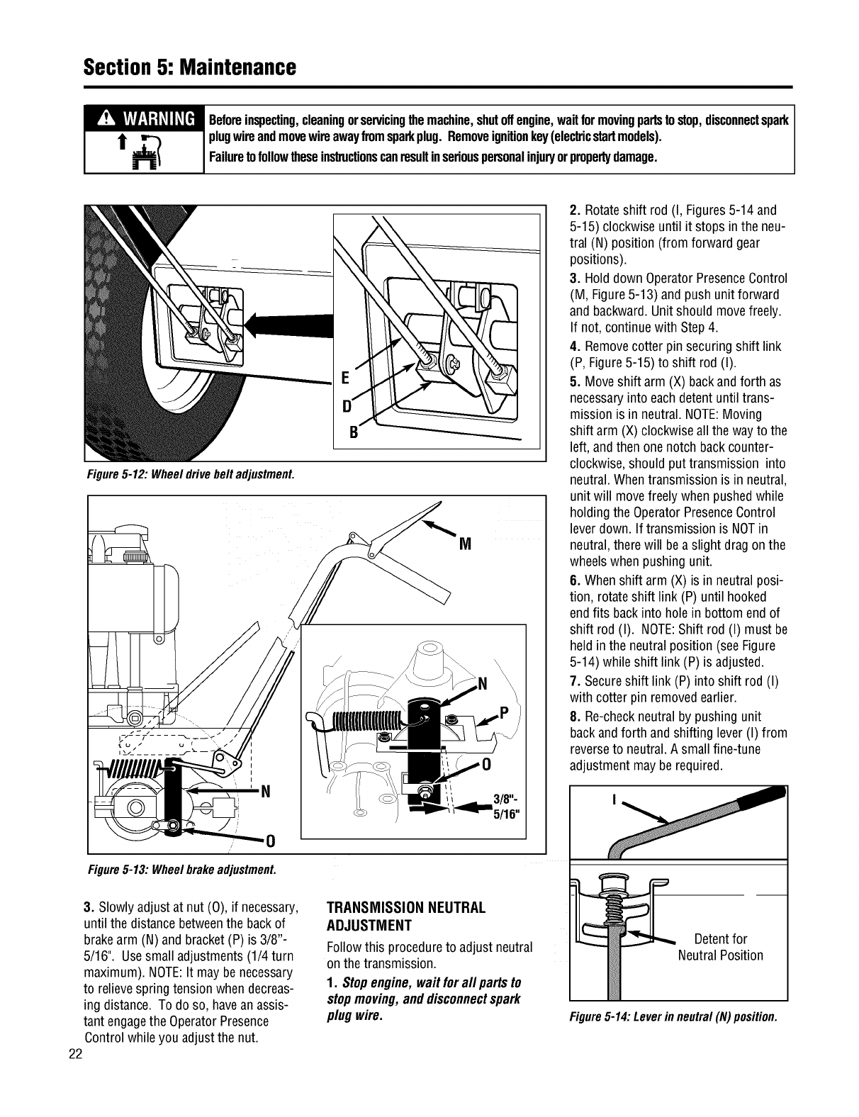
PresenceControl (M, Figure5-13).
21
Section5: Maintenance
W!_LW:I-'t_II_[_I Beforeinspecting,cleaningorservicingthemachine,shutoffengine,waitformovingpartstostop,disconnectspark
t_) plugwireandmovewireawayfromsparkplug.Removeignitionkey(electricstartmodels).
Failuretofollowtheseinstructionscanresultinseriouspersonalinjuryorpropertydamage.
Figure5-12: Wheeldrivebelt adjustmenL
M
i
I
I
i
'N
0
Figure5-13: WheelbrakeadjustmenL
3. Slowlyadjustat nut (0), if necessary,
until the distancebetweenthe backof
brakearm (N) and bracket(P) is 3/8"-
5/16". Usesmall adjustments(1/4 turn
maximum). NOTE:It maybe necessary
to relievespring tensionwhen decreas-
ing distance. To do so, havean assis-
tant engagethe OperatorPresence
Controlwhile you adjustthe nut.
22
TRANSMISSION NEUTRAL
ADJUSTMENT
Followthis procedureto adjust neutral
onthe transmission.
1. Stopengine, waitforall partsto
stopmoving,anddisconnectspark
plug wire.
2. Rotateshift rod (I, Figures5-14 and
5-15) clockwise until it stops in the neu-
tral (N) position (from forward gear
positions).
3. Hold down OperatorPresenceControl
(M, Figure5-13) andpush unit forward
and backward.Unitshould movefreely.
If not, continuewith Step 4.
4. Removecotter pin securingshift link
(P, Figure5-15) to shift rod (I).
5. Moveshift arm (X) backandforth as
necessaryinto eachdetentuntil trans-
mission is in neutral.NOTE:Moving
shift arm (X)clockwise allthe wayto the
left, andthen onenotch backcounter-
clockwise,should put transmission into
neutral.Whentransmission is in neutral,
unit will movefreelywhen pushedwhile
holdingthe OperatorPresenceControl
lever down. If transmission is NOTin
neutral,there will bea slight drag onthe
wheelswhen pushingunit.
8. Whenshift arm (X)is in neutral posi-
tion, rotateshift link (P) until hooked
endfits backinto hole in bottom endof
shift rod (I). NOTE:Shift rod (I) must be
held in the neutral position (seeFigure
5-14) while shift link (P) is adjusted.
7. Secureshift link (P) into shift rod (I)
with cotter pin removedearlier.
8. Re-checkneutral by pushing unit
backandforth andshifting lever (I) from
reverseto neutral.A smallfine-tune
adjustmentmaybe required.
Detentfor
NeutralPosition
Figure5-14: Leverin neutral (N)position.
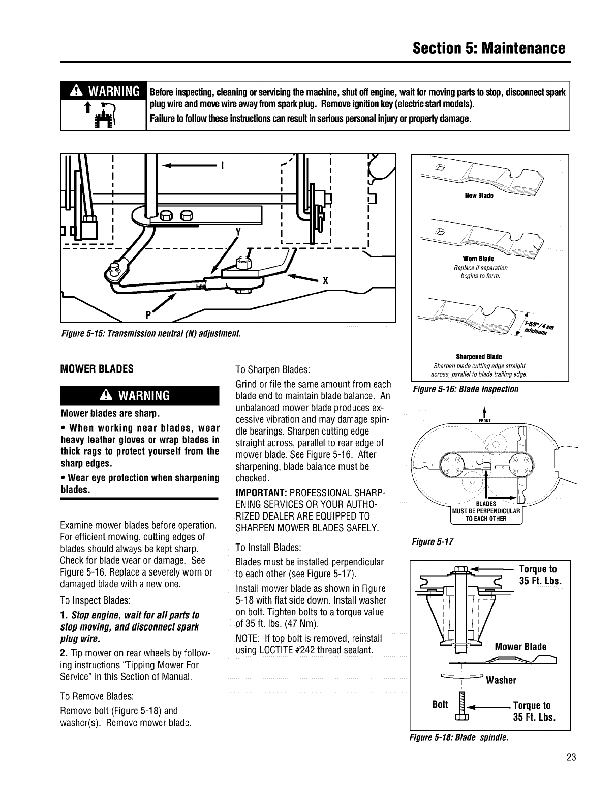
Section5: Maintenance
W!_IW:I-'t_II_[_I Beforeinspecting,cleaningorservicingthemachine,shutoffengine,waitformovingpartstostop,disconnectspark
t_plugwireandmovewireawayfromsparkplug.Removeignitionkey(ele_icstartmodels).
Failuretofollowtheseinstructionscanresultinseriouspersonalinjuryorpropertydamage.
I
I
I
I
I
I
PJj
Figure5-15: Transmissionneutral(N) adjustmenL
h
I
I
I
I
I
MOWER BLADES
Mowerbladesare sharp.
• When working near blades, wear
heavyleather glovesorwrap blades in
thick rags to protectyourselffrom the
sharpedges.
•Wear eye protectionwhensharpening
blades.
Examinemowerbladesbeforeoperation.
Forefficient mowing, cutting edgesof
bladesshould alwaysbekept sharp.
Checkfor bladewear or damage. See
Figure5-16. Replacea severelyworn or
damagedbladewith a new one.
To InspectBlades:
1. Stopengine,wait forall partsto
stopmoving,anddisconnectspark
plugwire.
2. Tip moweron rearwheelsby follow-
ing instructions "Tipping Mower For
Service"in this Sectionof Manual.
To RemoveBlades:
Removebolt (Figure5-18) and
washer(s). Removemowerblade.
To SharpenBlades:
Grindor file the sameamountfrom each
bladeendto maintainbladebalance. An
unbalancedmowerbladeproducesex-
cessivevibrationand maydamagespin-
dle bearings.Sharpencutting edge
straight across,parallelto rearedgeof
mower blade.SeeFigure5-16. After
sharpening,bladebalancemust be
checked.
IMPORTANT:PROFESSIONALSHARP-
ENINGSERVICESORYOURAUTHO-
RIZEDDEALERAREEQUIPPEDTO
SHARPENMOWERBLADESSAFELY.
To Install Blades:
Bladesmust beinstalledperpendicular
to each other (seeFigure5-17).
Install mowerbladeas shown in Figure
5-18 with flat side down. Install washer
on bolt. Tightenboltsto a torque value
of 35 ft. Ibs. (47 Nm).
NOTE: If top bolt is removed,reinstall
using LOCTITE#242 threadsealant.
New Blade
WornBlade
Replaceif separation
begins to form.
SharpenedBlade
Sharpenbladecutting edgestraight
across,parallelto bladetrailing edge.
Figure5-16: Blade Inspection
t
FRONT
BLADES
MUST BE PERPENDICULAR
TO EACH OTHER
Figure5-17
Torqueto
'-i
I
Washer
N
Bolt H< Torqueto
35 Ft. Lbs.
Figure5-18: Blade spindle.
23
Section5: Maintenance
w:_mw:ltt_ll_[_l Beforeinspecting,cleaningorservicingthemachine,shutoffengine,waitformovingpartstostop,disconnectspark
1__plugwireandmovewireawayfromsparkplug.Removeignitionkey(elecb'icstartmodels).
Failuretofollowtheseinstructionscanresultinseriouspersonalinjuryorpropertydamage.
BATTERYMAINTENANCE
Use extreme cautionwhenworkingon
or nearbatteries. To helppreventper-
sonalinjuryorpropertydamage:.
•Batteriesgenerate explosivegases.
Keepsparksand flames away from
the batteryat all times. Ventilatethe
area whenchargingorusingthe bat-
tery in an enclosedarea.
BatteryCarein Service
The batteryis sealedandis mainte-
nance-free.Acid levelscannot be
checked.
•Always keepthe batterycablesandter
minalscleanandfree of corrosive
build-up.
• After cleaningthe batteryandtermi-
nals,
apply a light coatof petroleumjelly or
greaseto both terminals
• Always keepthe rubber boot posi-
tioned
overthe positiveterminalto prevent
shorting.
Charging
Ifthetractor hasnot beenput into use
for anextendedperiodof time, charge
the battery with anautomotive-type12-
volt chargerfor a minimum of erie heur
at sixamps.
JumpStarting
IMPORTANT:Neverjump your tiller's
deadbatterywith the batteryof a run-
ning vehicle.
1. Connectend of onejumper cableto
the positiveterminal of the good battery,
then the other endto the positivetermi-
nal of the deadbattery.
2. Connectthe otherjumper cableto the
negativeterminal of the good battery,
then to the frameof the unit with the
deadbattery.
Failure to use this procedure could
cause sparking, and the gas in either
batterycould explode.
Cleaning
Clean the battery by removing it from
the tractor and washing with a baking
soda and water solution. If necessary,
scrape the battery terminals with a wire
brush to remove deposits. Coat termi-
nals and exposedwiring with grease or
petroleumjelly to preventcorrosion.
Battery Failures
Somecommon causesfor batteryfailure
are:
• incorrect initial activation
• undercharging
• overcharging
• corrodedconnections
• freezing
IMPORTANT:Thesefailuresare NOT
coveredby your tractor's warranty.
BatteryRemovalandInstallation
When removingandinstallingthe bat-
tery, disconnectandconnectthe cables
in this orderto avoid sparking:
1. To removethe battery,first discon-
nectthe negative(-) cablefrom the
grounding screw onthe backof the bat-
tery bracketpost. Bendthe cable away
from any metalparts.
2. Disconnectthe negative(-) cable
from the negative(-) batterypost.
3. Disconnectthe positive (+) cable
from the positive (+) batterypost and
bendit awayfrom any metalparts.
Coverthe cableterminalwith its rubber
boot.
4. Removethe batteryclamp.
5. To installthe battery,reversethe
abovesteps. Besurethat the battery
postsfaceto the rearof thetiller and
that the positive (+) post is onthe left
side as you faceforward from the han-
dlebars.
BatteryStorage
Chargebatteryfully. The battery loses
some of its chargeeachdaywhen the
unit is not used.
IMPORTANT:NEVERstore batterywith-
out afull charge.Rechargebatterybe-
fore returningto service or everytwo
months,whicheveroccursfirst.
Whenstoring unit for extendedperiods,
disconnectbatterycables.Removing
batteryfrom unit is recommended.
CLEANINGUNDERSIDEOF
MOWER DECK
Mowerbladesare sharp.
When working near blades, wear
heavyleatherglovesor wrapblades in
thick ragsto protectyourselffrom the
sharpedges.
Frequentlycheck,andcleanif necessary,
the undersideof the mower deck. Grass
build-upin this areacan affectthe cut-
ting performance.Beforeinspectingor
cleaning,makesure that the engineis
shut off andthesparkplug wire is
disconnectedfrom the spark plug.
Inspection/Cleaningof MowerDeck:
1. Stopengine, waitfor all partsto
stopmoving,anddisconnectspark
plug wire.
2. Tip mower on rearwheelsbyfollow-
ing instructions "Tipping Mower For
Service"in this Section.
3. Usea plastic or metalscraperto
removegrassbuild-upfrom deck or
blades.
24
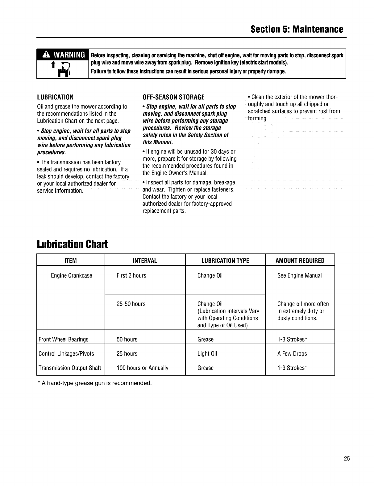
Section5: Maintenance
W!_[+_+I:I;t_II_[_I Beforeinspecting,cleaningorservicingthemachine,shutoffengine,waitformovingpartstostop,disconnectspark
i_ ,_) plugwireandmovewireawayfromsparkplug Removeignitionkey(elecbicstartmodels)
Failuretofollowtheseinsb_ctionscanresultinseriouspersonalinjuryorpropertydamage
LUBRICATION OFF-SEASONSTORAGE
Oiland greasethe moweraccordingto
the recommendationslisted inthe
LubricationChartonthe nextpage.
•Stopengine, waitforall partstostop
moving,anddisconnectsparkplug
wirebeforeperforminganylubrication
procedures
•Thetransmission has beenfactory
sealedand requiresno lubrication. If a
leakshould develop,contactthe factory
or your local authorizeddealerfor
serviceinformation.
•Stopengine, waitforall partsto stop
moving,anddisconnectsparkplug
wirebeforeperforminganystorage
procedures Reviewthe storage
safetyrulesin the SafetySectionof
thisManual
•If enginewill be unusedfor 30 daysor
more, prepareit for storageby following
the recommendedproceduresfound in
the EngineOwner'sManual.
•Inspectall partsfor damage,breakage,
andwear. Tightenor replacefasteners.
Contactthe factory or your local
authorizeddealerfor factory-approved
replacementparts.
•Cleanthe exteriorof the mower thor-
oughly andtouch up all chippedor
scratchedsurfacesto preventrust from
forming.
LubricationChart
ITEM
EngineCrankcase
INTERVAL LUBRICATIONTYPE
First 2 hours ChangeOil
ChangeOil
(Lubrication IntervalsVary
with OperatingConditions
andTypeof Oil Used)
25-50 hours
AMOUNTREQUIRED
SeeEngineManual
Changeoil more often
in extremelydirty or
dusty conditions.
FrontWheel Bearings 50 hours Grease 1-3 Strokes*
Control Linkages/Pivots 25 hours Light Oil A FewDrops
TransmissionOutputShaft 100 hours or Annually Grease 1-3 Strokes*
* A hand-type grease gun is recommended.
25
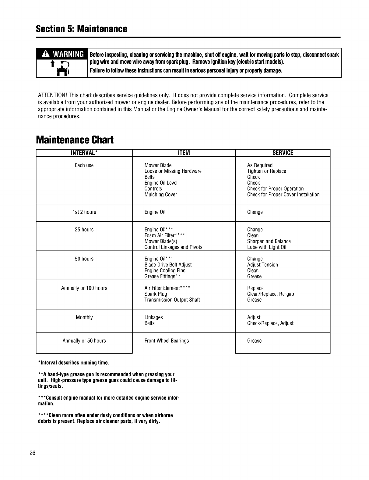
Section5: Maintenance
W!_[+_+I:I;t_II_[_I Beforeinspecting,cleaningor servicingthemachine,shutoffengine, wait for movingpartsto stop,disconnectspark
i_ ,_) plugwireandmovewireaway fromsparkplug. Removeignitionkey(elecb'icstartmodels).
Failureto followthese ins_ctions canresultinseriouspersonalinjuryorpropertydamage.
ATTENTION!This chart describesserviceguidelinesonly. It does not provide completeserviceinformation. Completeservice
is availablefrom your authorizedmoweror enginedealer.Beforeperformingany of the maintenanceprocedures,referto the
appropriateinformation containedin this Manualor the EngineOwner's Manualfor the correct safetyprecautionsand mainte-
nanceprocedures.
MaintenanceChart
INTERVAL*
Eachuse
1st 2 hours
25 hours
50 hours
Annually or 100 hours
Monthly
ITEM SERVICE
Mower Blade
Looseor Missing Hardware
Belts
EngineOilLevel
Controls
Mulching Cover
EngineOil
EngineOil***
FoamAir Filter....
Mower Blade(s)
Control Linkagesand Pivots
EngineOil***
BladeDrive Belt Adjust
EngineCoolingFins
GreaseFittings**
Air FilterElement....
SparkPlug
Transmission OutputShaft
Linkages
Belts
As Required
Tighten or Replace
Check
Check
Checkfor ProperOperation
Checkfor ProperCoverInstallation
Change
Change
Clean
SharpenandBalance
Lubewith Light Oil
Change
AdjustTension
Clean
Grease
Replace
Clean/Replace,Re-gap
Grease
Adjust
Check/Replace,Adjust
Annually or 50 hours Front Wheel Bearings Grease
*Interval describesrunningtime.
**A hand-typegreasegunis recommendedwhengreasingyour
unit. High-pressuretypegreasegunscouldcausedamageto fit-
tings/seals.
***Consult enginemanualfor more detailedengineserviceinfor-
mation.
.... Cleanmoreoftenunderdustyconditionsorwhenairborne
debrisis present.Replaceair cleaner parts, ifverydirty.
26
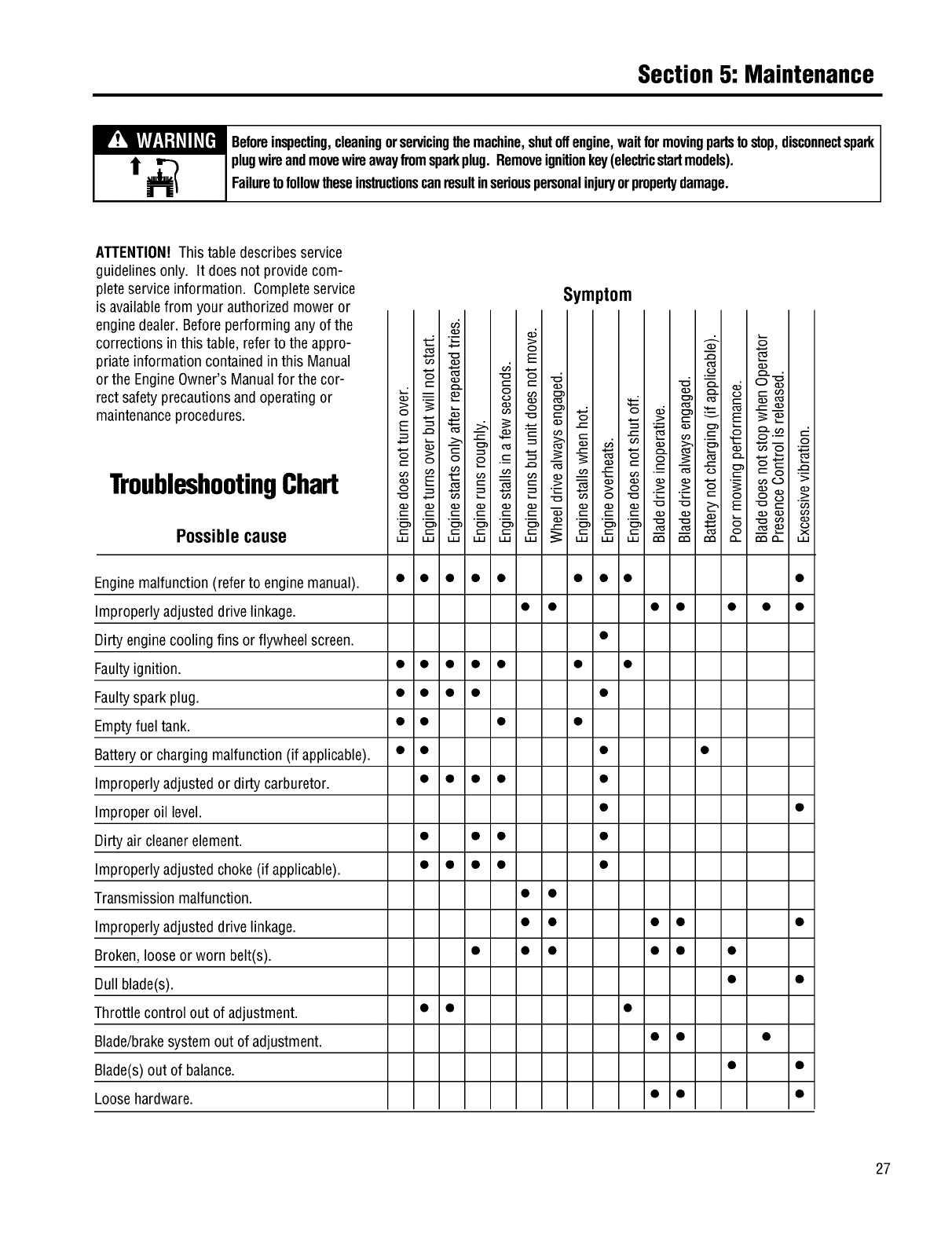
Section5: Maintenance
W!_[W:I-'i_II_[_I Beforeinspecting,cleaningorservicingthemachine,shutoffengine,waitformovingpartstostop,disconnectspark
i_ _) plugwireandmovewireawayfromsparkplug.Removeignitionkey(ele_icstartmodels).
Failuretofollowtheseinstructionscanresultinseriouspersonalinjuryorpropertydamage.
ATTENTION!This table describesservice
guidelinesonly. It doesnot providecom-
pleteserviceinformation. Completeservice
is availablefrom your authorizedmoweror
enginedealer.Beforeperformingany of the
correctionsin this table, referto the appro-
priate information containedin this Manual
or the EngineOwner'sManualfor the cor-
rect safetyprecautionsandoperating or
maintenanceprocedures.
Symptom
TroubleshootingChart
Possible cause
!nginemalfunction(referto enginemanual). • • • • • • • • •
mproperlyadjusteddrivelinkage. • • • • • • •
)irty enginecooling fins or flywheel screen. •
:aultyignition. • • • • • • •
:aultyspark plug. • • • • •
!mptyfueltank. • • • •
_atteryor charging malfunction(if applicable). • • • •
mproperlyadjustedor dirty carburetor. • • • • •
mproper oil level. • •
)irty air cleanerelement. • • • •
mproperlyadjustedchoke(if applicable). • • • • •
ransmissionmalfunction. • •
mproperlyadjusteddrivelinkage. • • • • •
_roken,loose orworn belt(s). • • • • • •
)ull blade(s). • •
hrottle control out of adjustment. • • •
_lade/brakesystemout of adjustment. • • •
_lade(s)out of balance. • •
.oosehardware. • • •
27
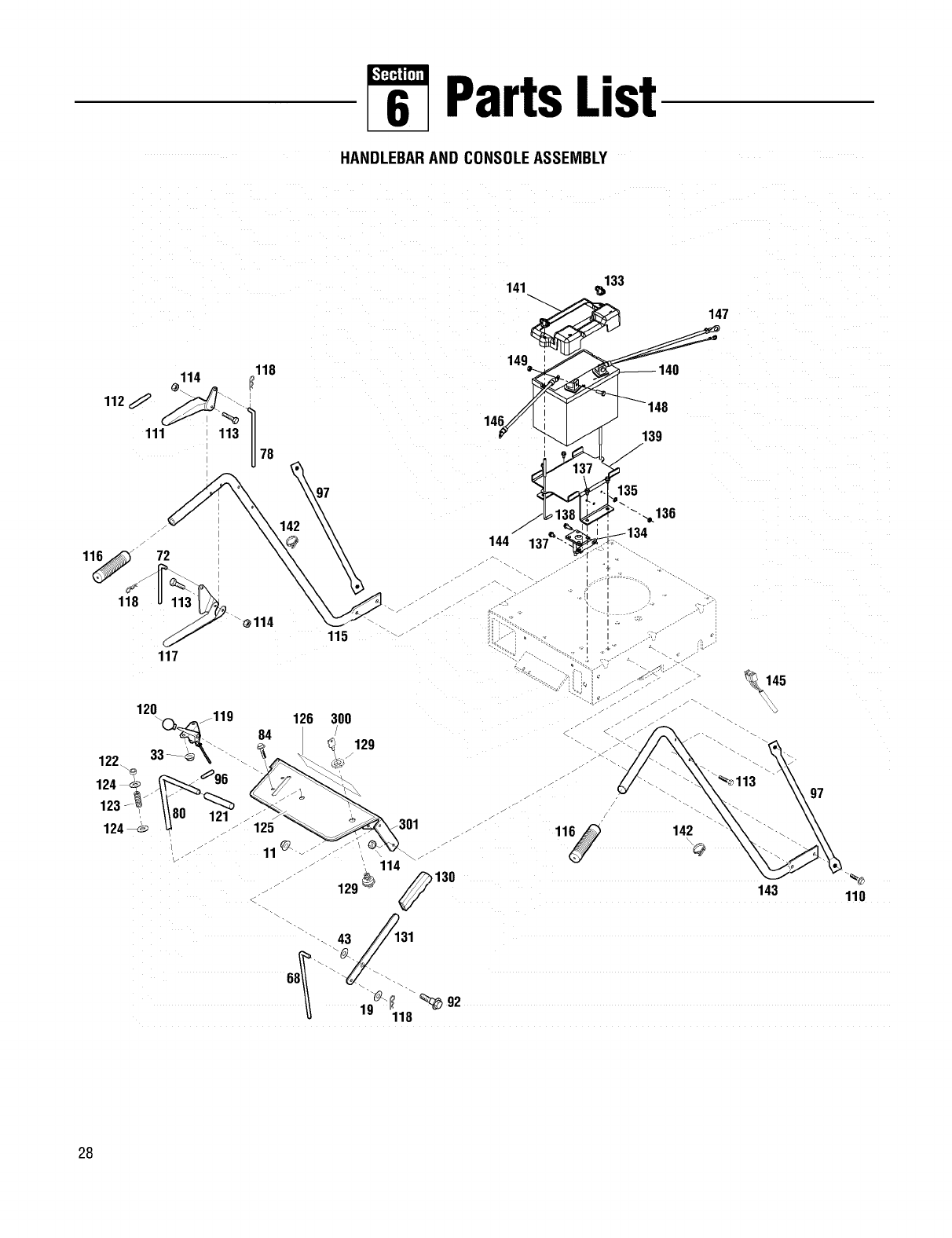
PartsList
HANDLEBARAND CONSOLEASSEMBLY
118
114
111 113 II
U
78
118
72
113
117
114
123 121
124
84
125
11
\
126
115
3OO
129
301
129 _
43
19 118
133
141 ,_
149_ 7
v_139
j_ 1_81_,"'"--._ 136
144 137 "_
r
"" S
130
142
@
92
_145
143
97
11o
28
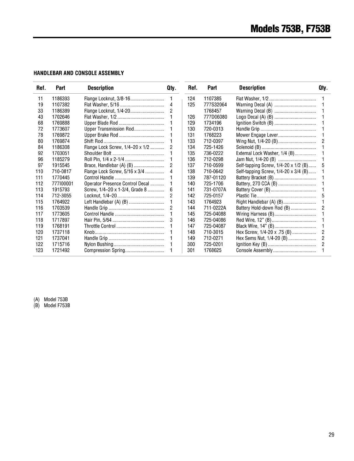
Models753B,F753B
HANDLEBARANDCONSOLEASSEMBLY
Ref. Part Description Qty.
11 1186393
19 1107382
33 1186389
43 1702646
68 1769888
72 1773607
78 1769872
80 1769874
84 1186308
92 1703051
96 1185279
97 1915545
110 710-0817
111 1770445
112 777100001
113 1915793
114 712-3055
115 1764922
116 1703539
117 1773605
118 1717897
119 1768191
120 1737118
121 1737041
122 1715716
123 1721492
FlangeLocknut,3/8-16........................... 1
FlatWasher,5/16 ................................... 4
FlangeLocknut,1/4-20........................... 2
FlatWasher,1/2..................................... 1
Upper BladeRod .................................... 1
Upper Transmission Rod........................ 1
UpperBrakeRod.................................... 1
Shift Rod ................................................ 1
FlangeLock Screw,1/4-20 x 1/2 ........... 2
ShoulderBolt ......................................... 1
Roll Pin, 1/4 x 2-1/4 ............................... 1
Brace,Handlebar(A) (B) ........................ 2
FlangeLock Screw,5/16 x 3/4 ............... 4
ControlHandle....................................... 1
OperatorPresenceControlDecal........... 1
Screw, 1/4-20 x 1-3/4, Grade8 ............. 6
Locknut, 1/4-20 ..................................... 2
Left Handlebar(A) (B) ............................ 1
HandleGrip............................................ 2
ControlHandle....................................... 1
Hair Pin,5/64 ......................................... 3
Throttle Control...................................... 1
Knob....................................................... 1
HandleGrip............................................ 1
Nylon Bushing........................................ 1
CompressionSpring............................... 1
Ref. Part Description Qty.
124 1107385
125 777S32064
1768457
126 777D06080
129 1734196
130 720-0313
131 1768223
133 712-0397
134 725-1426
135 736-0222
136 712-0298
137 710-0599
138 710-0642
139 787-01120
140 725-1706
141 731-0707A
142 725-0157
143 1764923
144 711-0222A
145 725-04088
146 725-04086
147 725-04087
148 710-3015
149 712-0271
300 725-0201
301 1768625
FlatWasher,1/2 ..................................... 1
Warning Decal(A) ................................. 1
Warning Decal(B) ................................. 1
Logo Decal(A) (B) ................................. 1
Ignition Switch (B) ................................. 1
HandleGrip............................................ 1
Mower EngageLever.............................. 1
Wing Nut, 1/4-20 (B) .............................. 2
Solenoid(B) ........................................... 1
ExternalLock Washer,1/4 (B)................. 1
Jam Nut, 1/4-20 (B) .............................. 1
Self-tapping Screw,1/4-20 x 1/2 (B)...... 5
Self-tapping Screw,1/4-20 x 3/4 (B)...... 1
Battery Bracket(B) ................................. 1
Battery,270 CCA(B) .............................. 1
Battery Cover(B) .................................... 1
PlasticTie............................................... 5
Right Handlebar(A) (B).......................... 1
Battery Hold-downRod (B) .................... 2
Wiring Harness(B)................................. 1
RedWire, 12" (B) ................................... 1
BlackWire, 14" (B)................................. 1
HexScrew, 1/4-20 x .75 (B)................... 2
HexSems Nut, 1/4-20 (B) ...................... 2
Ignition Key (B) ...................................... 2
ConsoleAssembly.................................. 1
(A) Model753B
(B) ModelF753B
29
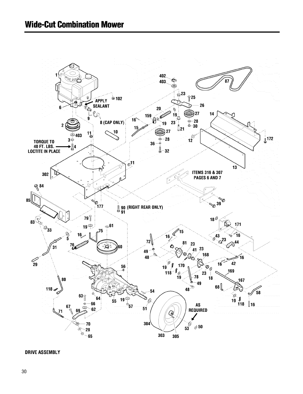
Wide-CutCombinationMower
402.
403.
J,
14
TORQUETO 3_ ;! J r 364
40 FT. LBS.,_-1_4
LOCTITEINPLACE _ 4- 32
I
f
12
I
_172
DRIVEASSEMBLY
3O
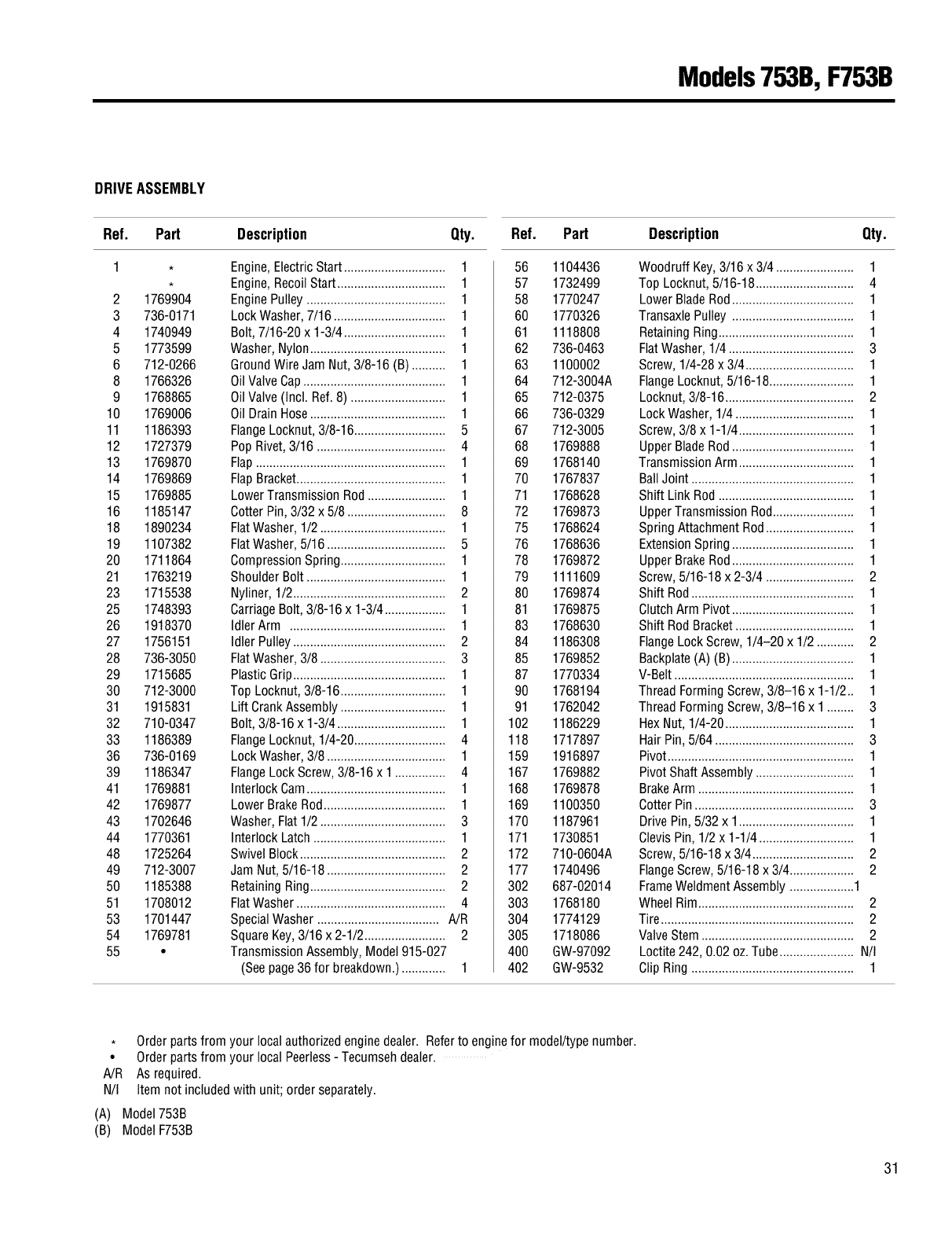
Models753B,F753B
DRIVEASSEMBLY
Ref. Part Description Qty.
2 1769904
3 736-0171
4 1740949
5 1773599
6 712-0266
8 1766326
9 1768865
10 1769006
11 1186393
12 1727379
13 1769870
14 1769869
15 1769885
16 1185147
18 1890234
19 1107382
20 1711864
21 1763219
23 1715538
25 1748393
26 1918370
27 1756151
28 736-3050
29 1715685
30 712-3000
31 1915831
32 710-0347
33 1186389
36 736-0169
39 1186347
41 1769881
42 1769877
43 1702646
44 1770361
48 1725264
49 712-3007
50 1185388
51 1708012
53 1701447
54 1769781
55 •
Engine,ElectricStart .............................. 1
Engine,RecoilStart................................ 1
EnginePulley ......................................... 1
LockWasher,7/16 ................................. 1
Bolt,7/16-20 x 1-3/4.............................. 1
Washer,Nylon........................................ 1
GroundWire Jam Nut, 3/8-16 (B) .......... 1
OilValveCap.......................................... 1
Oil Valve(Incl. Ref. 8) ............................ 1
OilDrain Hose........................................ 1
FlangeLocknut, 3/8-16........................... 5
Pop Rivet,3/16 ...................................... 4
Flap........................................................ 1
FlapBracket............................................ 1
Lower Transmission Rod....................... 1
Cotter Pin,3/32 x 5/8 ............................. 8
FlatWasher,1/2 ..................................... 1
FlatWasher,5/16 ................................... 5
CompressionSpring............................... 1
ShoulderBolt......................................... 1
Nyliner,1/2............................................. 2
CarriageBolt, 3/8-16 x 1-3/4.................. 1
Idler Arm .............................................. 1
Idler Pulley............................................. 2
FlatWasher,3/8 ..................................... 3
Plastic Grip............................................. 1
Top Locknut,3/8-16 ............................... 1
Lift CrankAssembly............................... 1
Bolt,3/8-16 x 1-3/4 ................................ 1
FlangeLocknut, 1/4-20........................... 4
LockWasher,3/8 ................................... 1
FlangeLockScrew, 3/8-16 x 1 ............... 4
Interlock Cam......................................... 1
LowerBrakeRod.................................... 1
Washer,Flat1/2 ..................................... 3
Interlock Latch ....................................... 1
SwivelBlock........................................... 2
Jam Nut, 5/16-18................................... 2
RetainingRing........................................ 2
FlatWasher............................................ 4
SpecialWasher .................................... A/R
SquareKey, 3/16 x 2-1/2........................ 2
Transmission Assembly,Model 915-027
(Seepage36 for breakdown.)............. 1
Ref. Part Description Qty.
56 1104436 Woodruff Key,3/16 x 3/4 ....................... 1
57 1732499 TopLocknut, 5/16-18............................. 4
58 1770247 LowerBladeRod.................................... 1
60 1770326 TransaxlePulley .................................... 1
61 1118808 RetainingRing........................................ 1
62 736-0463 FlatWasher,1/4 ..................................... 3
63 1100002 Screw,1/4-28 x 3/4................................ 1
64 712-3004A FlangeLocknut,5/16-18......................... 1
65 712-0375 Locknut,3/8-16 ...................................... 2
66 736-0329 LockWasher,1/4................................... 1
67 712-3005 Screw,3/8 x 1-1/4.................................. 1
68 1769888 UpperBladeRod.................................... 1
69 1768140 TransmissionArm .................................. 1
70 1767837 BallJoint ................................................ 1
71 1768628 Shift Link Rod ........................................ 1
72 1769873 UpperTransmission Rod........................ 1
75 1768624 Spring AttachmentRod.......................... 1
76 1768636 ExtensionSpring.................................... 1
78 1769872 UpperBrakeRod.................................... 1
79 1111609 Screw,5/16-18 x 2-3/4 .......................... 2
80 1769874 Shift Rod................................................ 1
81 1769875 Clutch Arm Pivot.................................... 1
83 1768630 Shift Rod Bracket................................... 1
84 1186308 FlangeLock Screw,1/4-20 x 1/2 ........... 2
85 1769852 Backplate(A) (B).................................... 1
87 1770334 V-Belt..................................................... 1
90 1768194 ThreadFormingScrew,3/8-16 x 1-1/2.. 1
91 1762042 ThreadFormingScrew,3/8-16 x 1 ........ 3
102 1186229 HexNut, 1/4-20 ...................................... 1
118 1717897 Hair Pin, 5/64 ......................................... 3
159 1916897 Pivot....................................................... 1
167 1769882 Pivot Shaft Assembly............................. 1
168 1769878 BrakeArm .............................................. 1
169 1100350 Cotter Pin ............................................... 3
170 1187961 Drive Pin, 5/32 x 1.................................. 1
171 1730851 Clevis Pin,1/2 x 1-1/4 ............................ 1
172 710-0604A Screw,5/16-18 x 3/4.............................. 2
177 1740496 FlangeScrew,5/16-18 x 3/4................... 2
302 687-02014 FrameWeldmentAssembly ...................1
303 1768180 Wheel Rim.............................................. 2
304 1774129 Tire......................................................... 2
305 1718086 ValveStem ............................................. 2
400 GW-97092 Loctite 242, 0.02 oz.Tube...................... N/I
402 GW-9532 ClipRing ................................................ 1
, Orderpartsfrom your localauthorizedenginedealer. Referto enginefor model/typenumber.
• Orderpartsfrom your local Peerless- Tecumsehdealer.
A/R As required.
N/I Item not includedwith unit; order separately.
(A) Model753B
(B) ModelF753B
31
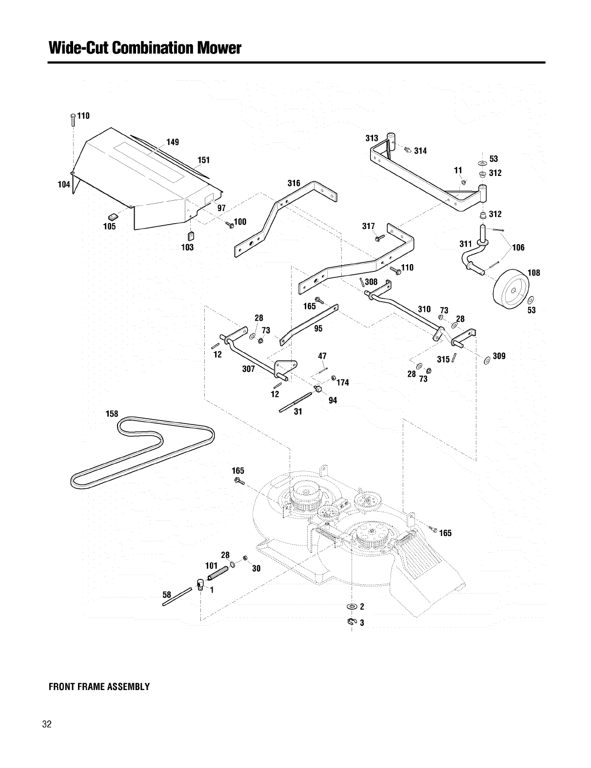
Wide-CutCombinationMower
_,110
O
105
149
151
103
313
314
53
11 312
158 12_31 94
28
oo_. 1 '"-` _._--_ _
_:_2
_'_3
165
FRONTFRAMEASSEMBLY
32
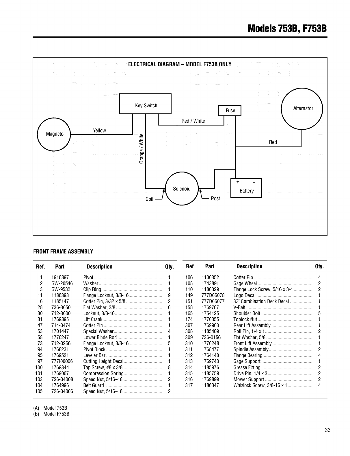
Models753B,F753B
I
ELECTRICALDIAGRAM- MODELF753BONLY
KeySwitch
I
Yellow
Coil
Red/White
/
Red
FRONTFRAMEASSEMBLY
Ref. Part Description Qty.
1 1916897
2 GW-20546
3 GW-9532
11 1186393
16 1185147
28 736-3050
30 712-3000
31 1769895
47 714-0474
53 1701447
58 1770247
73 712-0266
94 1768231
95 1769521
97 777100006
100 1769344
101 1769007
103 726-04008
104 1764996
105 726-04006
Pivot....................................................... 1
Washer................................................... 1
Clip Ring ................................................ 1
FlangeLocknut,3/8-16........................... 9
CotterPin, 3/32 x 5/8 ............................. 2
FlatWasher,3/8 ..................................... 6
Locknut, 3/8-16...................................... 1
Lift Crank................................................ 1
Cotter Pin ............................................... 1
SpecialWasher....................................... 4
Lower BladeRod.................................... 1
FlangeLocknut,3/8-16........................... 5
Pivot Block............................................. 1
LevelerBar............................................. 1
Cutting HeightDecal............................... 1
TapScrew,#8 x 3/8 ............................... 8
CompressionSpring............................... 1
SpeedNut, 5/16-18 ............................... 2
BeltGuard ............................................. 1
SpeedNut, 5/16-18 ............................... 2
Ref. Part Description Qty.
106 1100352
108 1743891
110 1186329
149 777D06078
151 777D06077
158 1769767
165 1754125
174 1770355
307 1769903
308 1185469
309 736-0156
310 1770248
311 1768477
312 1764140
313 1769743
314 1185976
315 1185759
316 1769899
317 1186347
Cotter Pin ............................................... 4
GageWheel............................................ 2
FlangeLock Screw,5/16 x 3/4 ............... 2
LogoDecal ............................................ 1
33" Combination DeckDecal.................. 1
V-Belt..................................................... 1
ShoulderBolt ......................................... 5
ToplockNut............................................ 1
RearLift Assembly................................. 1
RollPin, 1/4 x 1...................................... 2
FlatWasher,5/8 ..................................... 1
Front Lift Assembly................................ 1
Spindle Assembly................................... 2
FlangeBearing........................................ 4
GageSupport......................................... 1
GreaseFitting......................................... 2
Drive Pin, 1/4 x 3.................................... 2
Mower Support...................................... 2
WhizlockScrew,3/8-16 x 1.................... 4
(A) Model753B
(B) ModelF753B
33
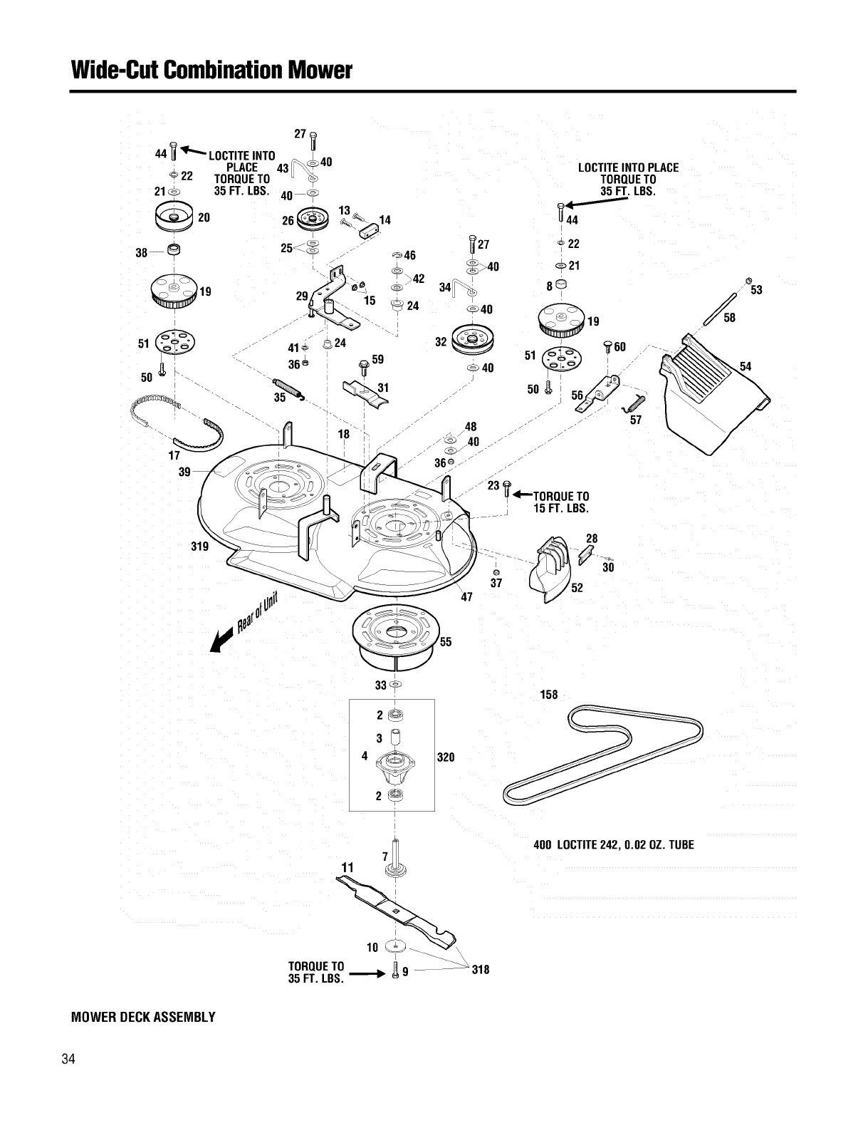
Wide-CutCombinationMower
19
LOCTITEINTO PLACE
TORQUETO
35 FT. LBS.
22
33
2@
:3@
4
2@
320
158
11
TORQUETO [19 _318
35 FT LBS _'_
400 LOCTITE242, 0.02 OZ. TUBE
MOWERDECKASSEMBLY
34
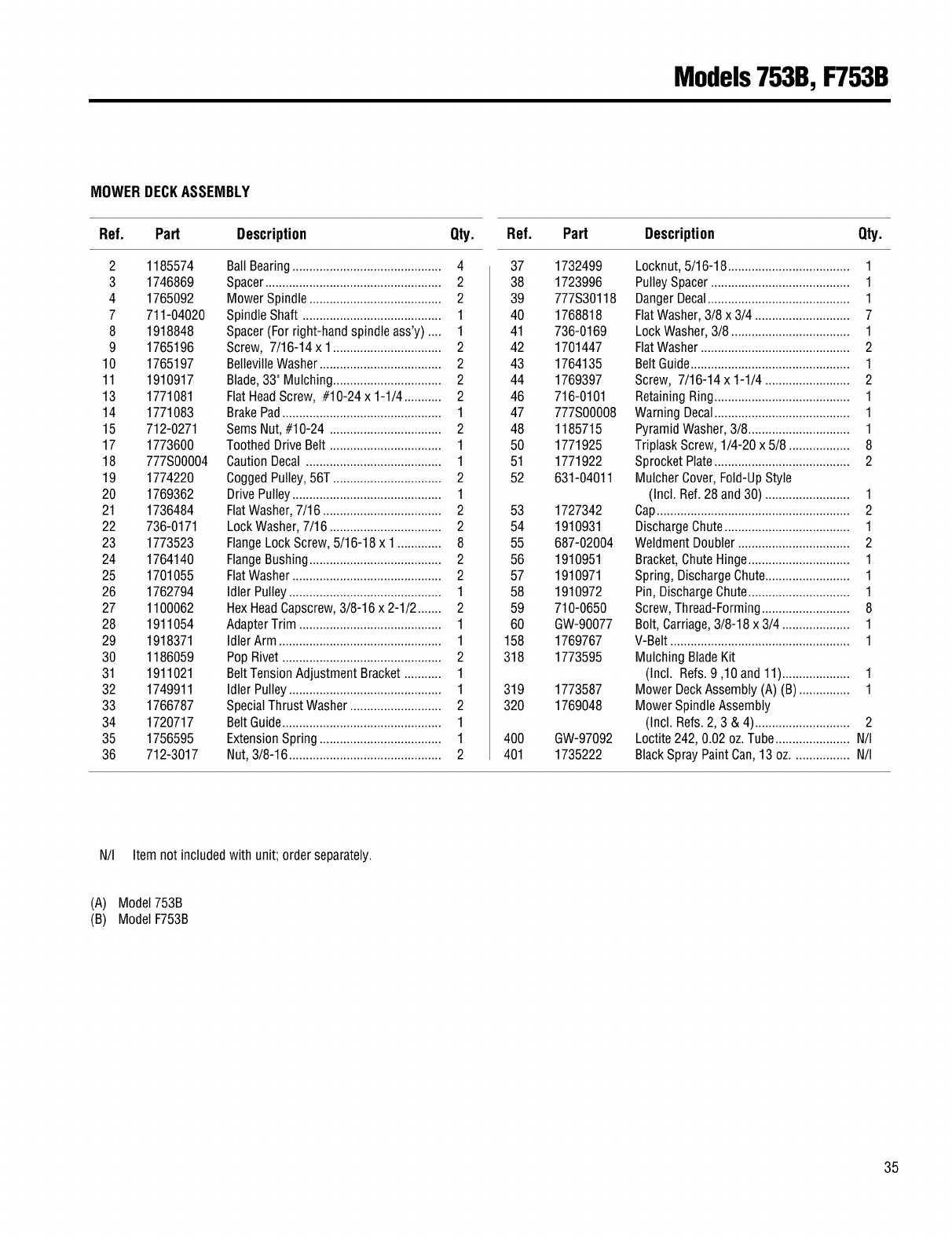
Models753B,F753B
MOWERDECKASSEMBLY
Ref. Part Description Qty.
2 1185574
3 1746869
4 1765092
7 711-04020
8 1918848
9 1765196
10 1765197
11 1910917
13 1771081
14 1771083
15 712-0271
17 1773600
18 777S00004
19 1774220
20 1769362
21 1736484
22 736-0171
23 1773523
24 1764140
25 1701055
26 1762794
27 1100062
28 1911054
29 1918371
30 1186059
31 1911021
32 1749911
33 1766787
34 1720717
35 1756595
36 712-3017
Ball Bearing............................................ 4
Spacer.................................................... 2
Mower Spindle....................................... 2
Spindle Shaft ......................................... 1
Spacer(For right-handspindle ass'y) .... 1
Screw, 7/16-14 x 1................................ 2
BellevilleWasher.................................... 2
Blade,33" Mulching................................ 2
FlatHeadScrew, #10-24 x 1-1/4 ........... 2
BrakePad............................................... 1
SeresNut,#10-24 ................................. 2
ToothedDrive Belt ................................. 1
Caution Decal ........................................ 1
CoggedPulley,56T................................ 2
Drive Pulley............................................ 1
FlatWasher,7/16 ................................... 2
LockWasher, 7/16 ................................. 2
FlangeLock Screw,5/16-18 x 1 ............. 8
FlangeBushing....................................... 2
FlatWasher............................................ 2
Idler Pulley............................................. 1
HexHeadCapscrew,3/8-16 x 2-1/2....... 2
AdapterTrim .......................................... 1
Idler Arm ................................................ 1
Pop Rivet ............................................... 2
BeltTensionAdjustmentBracket ........... 1
Idler Pulley............................................. 1
SpecialThrust Washer........................... 2
BeltGuide............................................... 1
ExtensionSpring .................................... 1
Nut, 3/8-16 ............................................. 2
Ref. Part Description Qty.
37 1732499
38 1723996
39 777S30118
40 1768818
41 736-0169
42 1701447
43 1764135
44 1769397
46 716-0101
47 777S00008
48 1185715
50 1771925
51 1771922
52 631-04011
53 1727342
54 1910931
55 687-02004
56 1910951
57 1910971
58 1910972
59 710-0650
60 GW-90077
158 1769767
318 1773595
319 1773587
320 1769048
400 GW-97092
401 1735222
Locknut,5/16-18.................................... 1
PulleySpacer......................................... 1
DangerDecal.......................................... 1
FlatWasher,3/8 x 3/4 ............................ 7
LockWasher, 3/8 ................................... 1
FlatWasher............................................ 2
Belt Guide............................................... 1
Screw, 7/16-14 x 1-1/4 ......................... 2
RetainingRing........................................ 1
Warning Decal........................................ 1
PyramidWasher, 3/8.............................. 1
TriplaskScrew, 1/4-20 x 5/8 .................. 8
Sprocket Plate........................................ 2
Mulcher Cover,Fold-UpStyle
(Incl. Ref.28 and 30) ......................... 1
Cap......................................................... 2
DischargeChute..................................... 1
WeldmentDoubler................................. 2
Bracket,ChuteHinge.............................. 1
Spring, DischargeChut_......................... 1
Pin,DischargeChute.............................. 1
Screw,Thread-Formin .......................... 8
Bolt, Carriage,3/8-18 x 3/4 .................... 1
V-Belt..................................................... 1
Mulching BladeKit
(Incl. Refs.9,10 and11).................... 1
Mower DeckAssembly(A) (B) ............... 1
Mower SpindleAssembly
(Incl. Refs.2, 3 & 4)............................ 2
Loctite242, 0.02 oz. Tube...................... N/I
Black SprayPaintCan,13 oz................. N/I
N/I Item not included with unit; order separately.
(A) Model753B
(B) ModelF753B
35
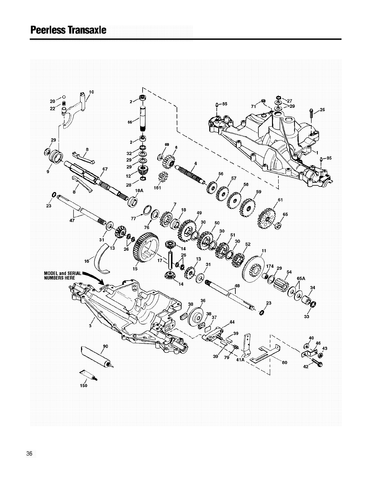
Peerl_Tra_xle
_29iiiiiiiiiiiiiiiiiiiiiiiiiiiiiiiiiiiiiiii
818A
iiiiii
iiiiiiiiiiiiiiiiiiiiiiiiiiiiiiiiiiiiiiiiiiiiiiiiiiiiiiiiiiiii/
iiiiiiiiiiiiiiiiiiiiiiiiiiiiiiiiiiiiiiiiiiiiiiiiiiiiiiiiiii31iiiiiiii
80 42
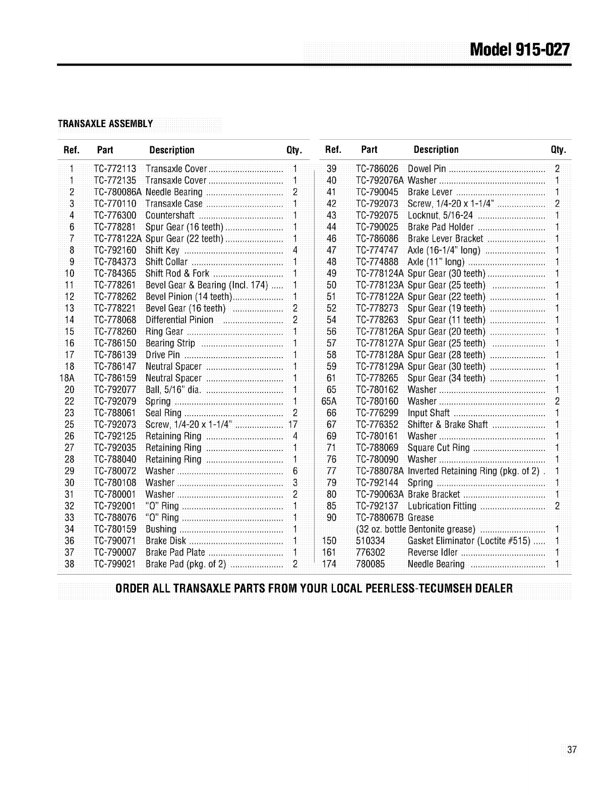
iiiiiiiiiiiiiiiiiiiiiiiiiiiiiiiiiiiiiiiiiiiiiiiiiiiiiiiiiiiiiiiiiiiiiiiiiiiiiiiiiiiiiiM de ii91i5- 7i
TRANSAXLEASSEMBLY
Ref. Part Description Qty. Ref. Part Description Qty.
2 TC-780086ANeedleBearing ................ 2 41 TC,790045 BrakeLeVeri..i .. .. .. .. .. .. .. .. 1
3 TC_770_10 TransaxleCaseii..ii..ii..ii..ii..ii..ii..ii.. 1 42 TC,792073 Screw_114_20x 1_1_4!!..ii..ii..ii..ii..ii 2
4 TC_776300 Countershaft i..ii..ii..ii..ii..ii..ii..ii..ii.. 1 43 TC,792075 Locknuti5f_6#24 .. .. .. .. .. .. .. _
6 TC_77828_ Spur Gear(_6 teeth) ii..ii..ii..ii..ii..ii.. 1 44 TC,790025 BrakePadHolder.............. _
7 TC-778_22ASpurGear(22teeth) .. .. .. .. .. .. 1 46 TC,786086 BrakeLeVerBracket .. .. .. .. .. .. _
8 TC_792_60 Shift Key.ii..ii..ii..ii..ii..ii..ii..ii..ii..ii.. 4 47 TC-774747 _le(_6-1!41flong) ............ _
9 TC_784373 Shift Collar ..ii..ii..ii..ii..ii..ii..ii..ii..ii.. 1 48 TC,774888 _le (_1'_long) ..ii..ii..ii..ii..ii..ii..ii..ii 1
10 TC_784365 Shift Rod & Fork .ii..ii..ii..ii..ii..ii..ii.. 1 49 TC,778124ASpur Gear(30 teeth).. .. .. .. .. .. _
1_ TC_77826_ BevelGear&Bearing(Incl. 174_.ii.. 1 50 TC,778123ASpur Gear(25 teeth) .......... _
12 TC-778262 Be_elPinion(14 teeth). .. .. .. .. .. 1 51 TC,778122ASpur Gear(22 teeth) . .. .. .. .. .. _
13 TC-77822_ Be_elGear(16_eeth_ . .. .. .. .. .. 2 52 TC,778273 Spur Gear(19 teeth) . .. .. .. .. .. _
14 TC_778068 DifferentialPinion .ii..ii..ii..ii..ii..ii.. 2 54 TC,778263 Spur Gear(l_ teeth) . .. .. .. .. .. 1
15 TC-778260 RingGear .................... 1 56 TC,778126ASpur Gear(20 teeth) . .. .. .. .. .. _
16 TC-786_50 BearingStrip .................. 1 57 TC,778127ASpur Gear(25 teeth) .......... _
17 TC_786_39 DrivePin.ii..ii..ii..ii..ii..ii..ii..ii..ii..ii.. 1 58 TC,778128ASpur Gear(28 teeth) . .. .. .. .. .. _
18 TC-786_47 NeutralSpacer ................ 1 59 TC,778129ASpur Gear(30 teeth) . .. .. .. .. .. _
18A TC-786_59 NeutralSpacer ................ 1 61 TC,778265 Spur Gear(34 teeth) . .. .. .. .. .. 1
20 TC_792077 Balli5i16'_dia. ii..ii..ii..ii..ii..ii..ii..ii.. 1 65 TC,780162 Washer..ii..ii..ii..ii.............. _
22 TC-792079 Spring....................... 1 65A TC,780160 Washer..ii..ii..ii..ii..ii..ii..ii..ii..ii..ii..ii 2
23 TC-78806_ SealRing..................... 2 66 TC,776299 InputShaft ii..ii..ii.. .. .. .. .. .. .. _
25 TC_792073 ScreWi_i4,20×l _l/4"ii..ii..ii..ii..ii.. _7 67 TC,776352 Shifter&Brake Shaft .......... _
26 TC-792_25 RetainingRing ................ 4 69 TC,780161 Washer..ii..ii..ii..ii.............. _
27 TC-792035 RetainingRing ................ 1 71 TC,788069 SquareOutRing .............. 1
28 TC-788040 RetainingRing ................ 1 76 TC,780090 Washer..ii..ii..i................ _
29 TC_780072 Washerii..ii..ii..ii..ii..ii..ii..ii..ii..ii..ii.. 6 77 TC-788078AInvertedRetainingRing (pkg. o_2) _
30 TC_780_08 Washerii..ii..ii..ii..ii..ii..ii..ii..ii..ii..ii.. 3 79 TC-792144 Spring ...................... _
3_ TC_78000_ Washerii..ii..ii..ii..ii..ii..ii..ii..ii..ii..ii.. 2 80 TC,790063A BrakeBracketii..ii..ii..ii..ii..ii..ii..ii..ii _
32 TC_79200_ "0" Ring ..ii..ii..ii..ii..ii..ii..ii..ii..ii..ii.. 1 85 TC,792137 LubricationFitting .ii..ii..ii..ii..ii..ii..ii 2
33 TC-788076 "O"Ring...................... 1 90 TC,788067BGrease
34 TC_780_59 Bushingi..ii..ii..ii..ii..ii..ii..ii..ii..ii..ii.. 1 (32OZ.bottle Bentonitegrease) .ii..ii..ii..ii..ii..ii..ii _
36 TC_79007_ BrakeDisk i..ii..ii..ii..ii..ii..ii..ii..ii..ii.. 1 150 510334 GasketEliminator(Loctite#515) .. _
37 TC_790007 BrakePadPlate i..ii..ii..ii..ii..ii..ii..ii.. 1 161 776302 ReVerseIdler .ii..ii..ii..ii..ii..ii..ii..ii..ii _
38 TC_79902_ BrakePad(pkg. of 2) ..ii..ii..ii..ii..ii.. 2 174 780085 NeedleBearing . .............. _
0RDER ALL TRANSAXLEPARTSFROMY0U R LOCALPEERLESS_TECUMSEHDEALER
37
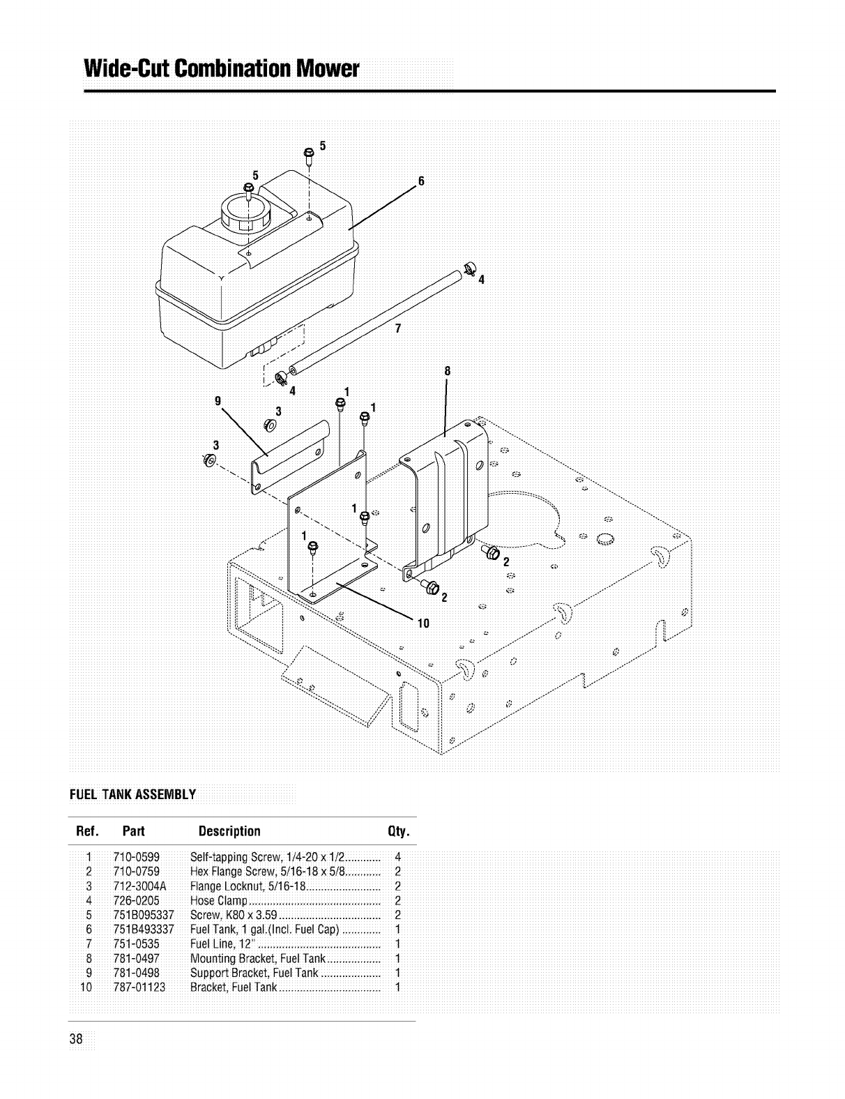
Wide,CutCombinationMower
.............................................................................................5iiiiiiiiiiiiiiiiiiiiiiiiiiiiiiiiiiiiiiiiiiiiiiiiiiiiiiiiiiiiiiiiiiiiiiiiiiiiiiiiiiiiiiiiiiiiiiiiiiiiiiiiiiiiiiiiiiiiiiiiiiiiiiiiiiiiiiiiiiiiiiiiiiiiiiiiiiiiiiiiiiiiiiiiii
iiiiiiiiiiiiiiiiiiiiiiiiiiiiiiiiiiiiiiiiiiiiiiiiiiiiiiiiiiiiiiiiiiiii5iiii
iii7iiiiiiiiiiiiiiiiiiiiiiiiiiiiiiiiiiiiiiiiiiiiiiiiiiiiiiiiiiiiiiiiiiiiiiiiiiiiiiiiiiiiiiiiiiiiiiiiiiiiiiiiiiiiiiiiiiiiiiiiiiiiiiiiiiiiiiiiiiiiii
iiiiiiiiiiiiiiiiiiiiiiiiiiiiiiiiiiiiiiiiiiiiiiiiiiiiiiiiiiiiiiiiiiiiiiiiiiiiiiiiiiiiiiiiiiiiiiiiiiiiiiiiiiiiiiiiiiiiiiiiiiiiiiiiiii_`!ii
FUELTANKASSEMBLY
Ref. Part Description Qty.
17!0-0599 Se!f-tappingS0rew;1!4÷20× 1/2 ...i;ii... 4
27!0-0759 HexFlangeScrew;5/t6-t8 × 5i8....iiii.... 2
37t2-3004A FlangeLocknuti 5/t6-t8 iiii., iiii., iiii.. 2
4 726-0205 HoseClamp 2
575t B095337 Screw, K80X3i59 2
6751 B493337 FuelTanki 1 gal (Incl. FuelCap)1
7 75!-0535 Fue!Line, 1211.iii:....iii:....iii:....iii:....iii:.... t
878t-0497 MountingBracket;FUelTank. iiii..iiii., t
9781 _0498 Suppo_ Bracketi FuelTank 1
10787-01123 Bracket;Fuel I
38_

iiiiiiiiiiiiiiiiiiiiiiiiiiiiiiiiiiiiiiiiiiiiiiiiiiiiiiiiiiiiiiiiiiiiiiiiiiiiiiiiiiiiiiiiiiiiiiiiiiiiiiiiiiiiiiiiiiiiiiiiiNoTE$iiiiiiiiiiiiiiiiiiiiiiiiiiiiiiiiiiiiiiiiiiiiiiiiiiiiiiiiiiiiiiiiiiiiiiiiiiiiiiiiiiiiiiiiiiiiiiiiiiiiiiiiiiiiiiiiiiiiiiiiii

ri_)iiiiiiiiiiiiiiiiiiiiiiiiii
The limited warranty set forth below is given by TrOy,Bilt LI_C d Troy, Bilt LLC does not extend any warranty for products
with respecttonewmerchandisepurchasedandusedinthesoldorexportedoutside of the United States; itspos*
united States, its poSseSsions and terr!t0ries sessions and terr!t0ries, except those sold thr0Ugh Troy_
B!lt LLCIs authOriZed Channels of export distribution
Troy_Bift LLC warrants this pr0dUCt against defects for a period eParts that are not genuine Troy-Bi!t parts are not covered by
Of tw0 (2)years C0mmencing on the date 0f original pUrChase thiswarran_
and willi at its opt!on;repair or rep!ace, free of chargei any part f. Se_ice comp!eted by someone other than an authorized
found tebe defective in materia!s or workmanship This !!ra!ted servic edealer is not CoVered by this warranty.
warranty shall oniy apply if this prodUCthas been 0perated and g TransportatiOn charges and sewiCe caiis are not Covered
maintained in accordance with the Operat0¢s Manua! furnished
with the product; and has not been subject to misusei abUse; No implied warrantyi including any implied warranty of met,
commercial use;neglect; accident;improper maintenancei alter_ chantabllity of fitness for aparticularpurposeiappllesafter
ation; Vandalism, theft;fire; water; or damage because 0f other the applicable period of express written warranty above as
per!! 0r natura! disaster. Damage resulting _rom the installation to the parts as ident ified. No other express warrantyi
or use of any accessory or a_achment not approved by Troy-Bi!t whether written or oral, except as mentioned abovei given
ELC for use W!ththe prodUct(s)Covered by this manual w!]] Void by any person or entityi including adealer or retaileri with
your warranty as to any resulting damage respect to any producti shatl bind Troy,Bilt LLCi During the
period of the warranty ithe exclusive remedy is repair or re-
Nermai wear parts or Components thereof are subject to sepa, placement of the product as set forth above:
rate terms as fo!!ows: A!!normal wear parts or component fail_
ures wi!! be CoVered on the product fora period of 90 days re-The provisions asset forth in this warranty provide the sole
gard!ess of cause After 90 days, but within the two year period; and exclusive remedy arising from the sale. Troy, Bllt LLC
normal wear part failures will be CoVered ONLY IF caused by de_ shall not be liable for incidental or consequential loss or
fects in materia!s or workmanship of OTHER Component parts damage includingi without limitationi expenses incurred for
Norma! wear parts and components inClUde;bUt are not !imited substitute or replacement lawn care services or for rental
to:batteries; be!ts; biades, b!ade adapters, grass bags; rider expenses to temporarily replace awarranted product;
deck whee!s;seats;sn0w thrower skid shoes; shave p!ates;
auger spira !rubber; tires some states do not allow the exclusion or limitation of incidenta!
or consequential damages, or limitations on how !ong an implied
HOW TO OBTAIN SERVICE; Warranty service is avaifable; warranty !asts; so the above exclusions or limitations may not
WITH PROOF OF PURCHASE throug_ your local authoriZed apply to you
service dealer. To locate the dealer in your area, check your
Ye!!owPage s;0rcontactTroy_ Bilt LLCatP.O Box361131; In no eVent sha!l rec0very of anyk !rid be greater than the
cleveiand, Ohi0 44136"0019;1 866"840"6483; or leg on toour amount of the purchase price of the product s0id. Alteration of
Web site at www troybilt.com the safety features of the product shall void this warranty;
¥0U assume the nsk and liability for loss; damagei or injury to
This !imited warranty does not provide coverage in the following you and your property and!or t0 others and their property arising
cases: OUtof the misuseor inability t° Usethe prodUCt.
The eng!ne or component parts thereof. These!tems
carry a separate manufacturer's warranty Refer to the This limited warranty shall not extend to anyone other than the
app!icabie manufacturer's warranty for terms andC0 nd origina! pUrChaser or to the person for wh0m it Was purchased
tions as a gift;
b Log spl!tter pumps, va!Ves, and Cyl!nders have a separat e
one year warranty. HOW STATE LAW RELATES TO THIS WARRANT¥i This
C. Routine maintenance items sUCh as !ubricants, filters; timited warranty gives you specific legal rights, andyou
b!ade sharpening; tune-u ps, brake adju stments;c!utch may also have other rights which vary from state to state;
adjustments, deck adjustments; and normal deterioration of
the exterior finish due to Use or exposur e
TROY_BILT LLCi P.Oi BOX 361131i CLEVELAND iOHIO 44136.0019i 1.866.840.6483
4g_
