Troybilt 21A 675B063 User Manual TILLER Manuals And Guides L0404237
TROYBILT Rear Tine, Gas Tiller Manual L0404237 TROYBILT Rear Tine, Gas Tiller Owner's Manual, TROYBILT Rear Tine, Gas Tiller installation guides
User Manual: Troybilt 21A-675B063 21A-675B063 TROYBILT TILLER - Manuals and Guides View the owners manual for your TROYBILT TILLER #21A675B063. Home:Lawn & Garden Parts:Troybilt Parts:Troybilt TILLER Manual
Open the PDF directly: View PDF ![]() .
.
Page Count: 36

_i_)iiiiiiiiiiiiiiiiiiiiiiiiiiiiiiiiiiiiiiiiiiiiii
Rear, tineTillerModel
M0del 675B ShOwn(bumper sy!eSVa_)
I M PO RTANT:READ SAFETY RUL ES AND INSTRUCTIONS CAR EFULLY
Warning: This unit is equipped with an interna ! combustion engine and shou!d not be used on or near any un!mproved forest-covered; brush-
covered or grass-covered land unless the eng!nels exhaust system !s equip_d with a spark arrester meet!ng app]!cab!e Iota! or state laws (if any) i
!f a spark arrester is used, !t shou!d be maintained in effect_e working order by the operatori In the State of California the above is requ!red by law
(Sect!on 4442 of the California Pub!ic Resources Code)i Other states may have s!mi!ar !awsi Federa! !aws apply on federal landsi A spark arrester
for the muff!er is ava!lab!e by contacting the service department at Troy-Bi!t LLC; PiOi Box 361131 Cleveland, Ohio 44136-0019i
TROY-BILT LLC, ROi BOX 361131i CLEVELAND, OH 44136,0019
PRINTED IN USA FROM NO: 769,00586
TABLEOFCONTENTS
Content Page
Calling Customer Support : : i i..i i : : : : i i.i i : : : : i i..i i : : : i i i.i i : : : : i i.i i i : : :2
Safety::::.i;:; ; ; ; ; ;; ;:3
Assemblyi i. i ; i ; ; ; ; ; ;; ; i6
Features and Controls:.:::;: : : :..: : : : : : : :.: : : : : : : :..: : : : : : : :.: : : : : : : :.: : : : : :8
Operation : : : : : :: : :t t
Maintenance iii ; iiii.iiii; iii..iii; iiii.iiii; iii.iiii; iiii.iii;; iii.iiii; it6
Troubleshooting ::::i.;;;::::i..;;:::::i.;;:::::i.;;;::::ii.;;:::::i.;;;::;22
Parts List : : : : : : : :24
War,any Information : :. i i i : ; ; ; ; ;; ; :Back Co_er
FINDING
This Operator's Manual is an important part of your new Rear,tine Tillerilt will help you assemble; prepare and main,
tain the unit for best performance: Please read and understand what it says:
Before you start assem bling you r new eq uipment; please locate the model plate on the equipment and copy the infor,
mation from it in the space provided below: This information is ve_ important if you need help from our Customer
Support Department oKan authorized dealeri
• You can locate the model number by looking at the rear surface of the tine shield: A sample model plate is
explained below. For futu re refe fence; please copy the model number and the serial number of the equipment
in the space below
Copy Model Number Here
www:t rovbilt:com CLEVELANDi0H44136
_330;558,7220
_866-840-6483
ENGINEINFORMATION
_he engine manufacturer is responsible for all engine-related issues with regards to performance; power-_ating, speci-
ficationsi warranty and servicei Please refer to the engine manufactureCs Owner's/Operator's Manual packed sepa,
rarely with your unit for more informationi
CALLINGCUSTOMER
If you have difficulty assembling this product or have any questions regarding the controls; operation or maintenance
of this unit, please call the Customer Support Department;
Call 1-(330)558,7220 or 1, (866) 840-6483 to reach a Custome r Support representativei Please have
'_ your unit!s model number and serial number ready when you Call:See previous section to locate this infor,
mationi You will be asked to enter the seiial numbei in oidei to piocess your call
SPARK ARRESTER WARNINGTO RESIDENTS OF
CALIFORNIAAND SEVERALOTHER STATES
Under Oaliforn ialawiand Under the laws of several
other states; you are not permitted to operate an inter.
halcombustion engine usinghyd rocarbon fuels on any
foresL brushi hay;grainiorg rass covered land;or land
Covered by any flammable agtic ultural Ctop without an
engine spark arrester in continuous effective working
order.
Theengine on theunit is an internal cornbustionengine
which burns gasolinei a hydrocarbon fueli and must be
eq uipped with aspark arrester muffler in continuous
effective working orderi The spark arrester must be
attached to the engine exhaust sYstem in such a
manner that flames or heat from the system willnot
ignite flammable material: Failureof the owner/opera-
tor of the unit to cornply with this regulation is a mis,
demeanor under California law (and other states) and
may also be a violation of other state and!or federal
reg ulations, laws; ordinances or codesi Conrad your
local fi re marshal or forest service for specific informa,
tion about which regulations apply in your area.
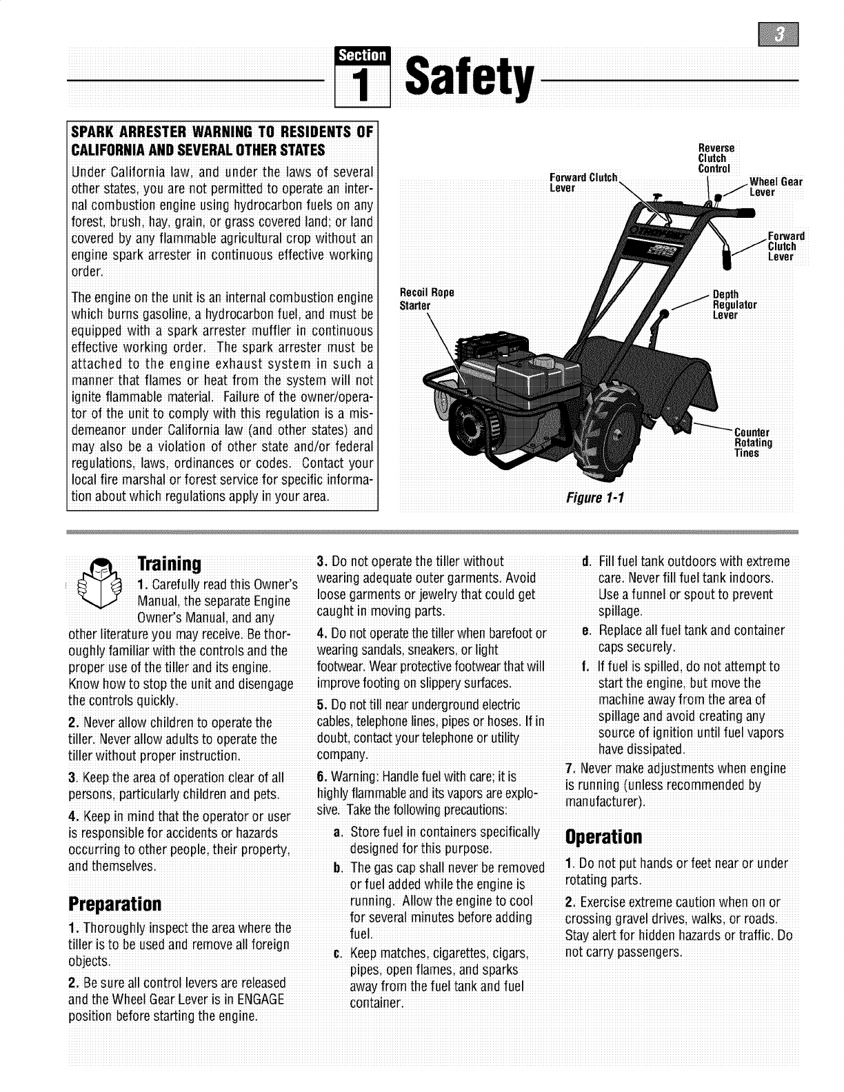
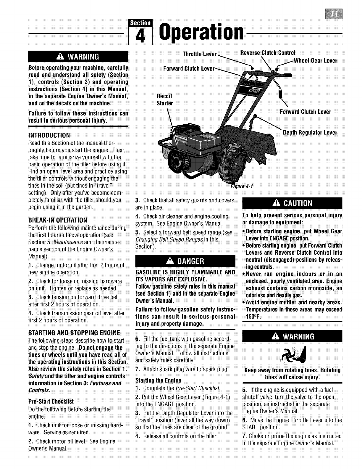
Reverse
Clutch
Control
ForwardClutch i ...... luh,,,, n,,_,_
Leve I ..............
Forward
h
RecoilRope
Starter lulator
iiiiiiiiiiiiil
Rotatingiiiiiiii
Tines
iiiiiiiiiiiiiiiiiiiiiiiiiiiiiiiiiiiiiiiiiiiiiiiiiiiiiiiiiiiiiii_urei1i.1iiiiiiiiiiiiiiiiiiiiiiiiiiiiiiiiiiiiiiiiiiiiiiiiiiiiiiiiiiiiiiii
Training 3: Do not operatethe tiller without d. Fill fuel tank outdoors with extreme
1 r f ii-i ihi wn r, wear'ng adequateouter garmentS Avo'd care Neverf ' fue tank'ndoors
,,Ca e u y Bad sO e
loose garmentsor ]ewel_ that could get Useafunnel or spout to prevent
Manual, the separateEngine ........ .......
............... wnii Mn I nd n................caught in moving parts...........................................................spillage............................................................
0 e s ia ua,a a
other literature you may receive Bethori 4: Do notoperate the tiller when barefootore. Replaceall fuel tank andcontainer
oughly familiar with the controls and the wear ng sandals;Sneakersior light capssecurely
proper use of the tiller andits engine: footwear.Wear protectivefootwear that will l, lf fuel is spilledi donor attempt to
Know how to Stopthe unit and disengage improvefooting onslippe_ surfaces, start the enginei but move the
the controls .machine away from the areaof
• 5, Do not t!ll nearundergroundelectnc :
li' r i spillage ariaavOIOcrea:lng any.............
2, Neverallow children to operatethe cables,telephone nesi plpeso hose& If n,, : :
source of ignition until fuel vapors
iiller Neverallow adults to operatethe doubt contactyour telephoneor utility !
r': r coman havedissipated
tille withoutproperlnstuctloni P Yi _ i i ,: il i i :
. : ; t\Jevermake aejusl:menl:swnen engine
&Keep the areaof operation clear of all&Warning: Handlefuelwith care;it isis r_nnin" _unless "_ _"_'_ _:
g _ ruuul_mluuuuu uy
pe#sons;pa#ticuladychildren and pets highly flammable and its vaporsareeXplo; _, ;,_; ;_
÷ _. II IdllU_dbLU EUE,li
4KeG inmin thtth oertor r......er..........slve taKe[neToliowlngprecau1:ions..............................................................................................................
p d a: e p a: o us
is responsiblefor accidentsor hazards a; Store fuel in containers specifically 88eratiGn
occurring to other people; their property; designedfor th s purposei _,-c--_-_
and themselves Th h II n v r r m v 1 Do not put hands or feet nearor under
i iii i i!. b; egascapsiaii ieeibe e ioed.
or fuel added while the engine iS rotat!ngparts.
............. ........ running AIIow the engine to cool 2 Exerciseextreme Cautionwhen on or
Preparation ...... ............
; i. for several rainutes before add gravel drives; walksi or roads
1/horoughly inspect the areawherethe
fue Stay alert for hidden hazardsor traffic. Do
tiller is to beused andremove all foreign _ _L_LL_ Li_L_L_,._ not cai"' _assen'_ers
UUJUUL;5.............................................................................................. ....................................................................................................................................................................
pipes,open flamesi and
2; Be Sureall control leversare released away from thefuel tank andfuel
andihe Wheel GearLe_er iSin ENGAGE cont'aineri
position before starting the engine.
3. After striking a foreign object, stop the 14: Beawarethat the tiller may unexpeCb Speed:Authorizedservice shall besoughtif
engirle,remove the wire from the ;spark edly bounce upward or jump backward if a problemexistsi
plug wire and preVent it from touching the the tinessh ould strike extremel!i hard 24 Do noi touchengine Da_swhich mavbe
spark plugi thoroughly respectthe packedsoil, frozen groundi or buried hoifrom oDerationiLet Da2rtscool down
machinefor any damagei and repair the obstacles like large stones, roots; or sufficientli
damage before restart!ng and operating stumps; If !n doubt about the t!lhng cond!-L _
the machinei tionsi always use the following operating 2_i _!easeremem_e_:_ou cana_waysStop
the l:lnesandWlleelsby releasingtile
4i E×ercise caution to avoid slipping or precaut!°nst° ass!st Y°u !n mamta!mng F_rw_P"1 i_h L"v_i _iih" RXv_r_ _1 i_h
_.i_ control of the tiller: U _u_u_ u _ _u
Control(whichever leveryouhave engaged)
5i If thou nit shouId start to Vibrateabnori a+ Walk beh_ndand to ones_dee! the orbYmo_ingtheThiottle ControlLeVei to
mallv sfonfhe ermine disconnectfhe snark tiller, usingone handon the han-
p"iug'wiieand pie've'ntlit from'i"ou_h_"rlgihe_ i Relaxyourarm; but pi_ thi tillii i ii thi
's_anu_i
causei Vibiaiion isgeneially a waining of Use slower engine speodsi ,
zt use extremecaul:lOnwren reversingor
troublei Clearthe tilling area otall large i
6Sto Lihe engine disconneciihe s_aik stonesi roots and other debris:pull! ngthe machinetowards youi
• _ i ; !lJ
plug wire and preventit from touching the d; Avoid usingdownward pressure on 28: Sta_the enginecare!ull_accord[rlgto
spaik plugwhe neveryou leavethe opeiaii handlebars i I1need be i useslight nstruo:lonsandwire Tee_WellawayTromme
ing positiom before unclogging the tines, upwardpressure to keep the tines ! nes
or when making any repairs;adjustments lrom digging too deeply; 29: Neverpick upor car_ a machinewhile
or inspectionsi e; Beforecontactinghard packedsoil the engineis runningi
moving partshave stoppedi Disconnect 15: Do not o_erloadthe tiller's capaci_ by dition
the sparkplug wire and prevent it from attempting to till too deeplyat too fast a __
:r:t: _. t_Jevers_orethe[lller wen TUelIn[ReTUel
[OUgrllng£nespark plug I:oprevem accl-a [aRK InsIge a OUIIOlng wnere Ignl£10n sources
aen_als[amng 16; Neveroperate thetiller at high transi arepresent suchashot waterandspace
9. Alwayskeep the tiller tine hood flap port speedson Slippe_ su_aces. Look heaters;furnaces;clothes dryers;stoves
down behineand usecare when backing uP electricmotors;etc;)Allow engineto Cool
10: Neveruse thetiller unlesS proper 17: Donot operate the tiller ona Slope befo[estoring inany enclosu[e:
gaards; plates;orother Safe_ protective that is too Steepfor safety: When o[14. To reducethe chancesof a fire hazard;
devicesare in placei slopesi slow down and make sure you keepthe enginefree Ofgrass,leaves;or
havegood footing Never permetthe teller excesseve rease
11i Donot Curlengine in anenclosed aiea. i i !i i ii
:to freewheeldown Slopesi i.
Erlgne exhaust contains carborl monox!de 5_Store gasohrle m acool, well-verlblated
gas; a deadly pc ison that is odorless coI-18 :Never allow bystandersnearthe unit: areaisafely awayfrom any spark: or flame:
oflessi and !as!eless. 19: Only use attachments and accessories p[oducing equipment store gasoline in an
12: Keepchild ten andpets away. that areapproved by GardenWay Inci approved container, safely awayfrom the
ENGAGEtFREEWHEE[_ In this-osition :.ii ..: Maintenancesection of this ManUaland
...... ,, Z'l, Neveropera_:eme _:lllerwl_:nou_gooa thx_r_t. ,Enfin" nwnXi'_ M_ni_1f"r
the wheelswill not hold the tiller back visibilih_or linht e ,_e_:: u _ _ a u,,
andthe revolvingtines cozddpropelthe " _' instructionsif thetiller iSto be Storedfor
tiller rapidly bac_ardi possiblycausing 22i Neveroperatethetiller ifyou aretired, or an extendedperiod
loss of control Alwa"s movethe Wheel underthe inflUenCeof alcoholidrugs or ,.
mealcaEiofl
Gear Leverto ENGAGEbeforesta_ing iurlning or thespaik plug wiie
engineo[ engagingthe tines/wheels with 23i Operatorsshall not tampei withthe _onnected,except when sPecificall7
the Forward Clutch or the ReverseClutch: engine-governorse_ingson the machine; instructedto dosoi
!he _;m° ic_ln_r°ls thett_ximu mSafned & If the fuel tank hasto bedrained, do this
ope_ g ;_ ;_ _ outdoors
!o gpa!s o !oa agecauseeD_oe- i
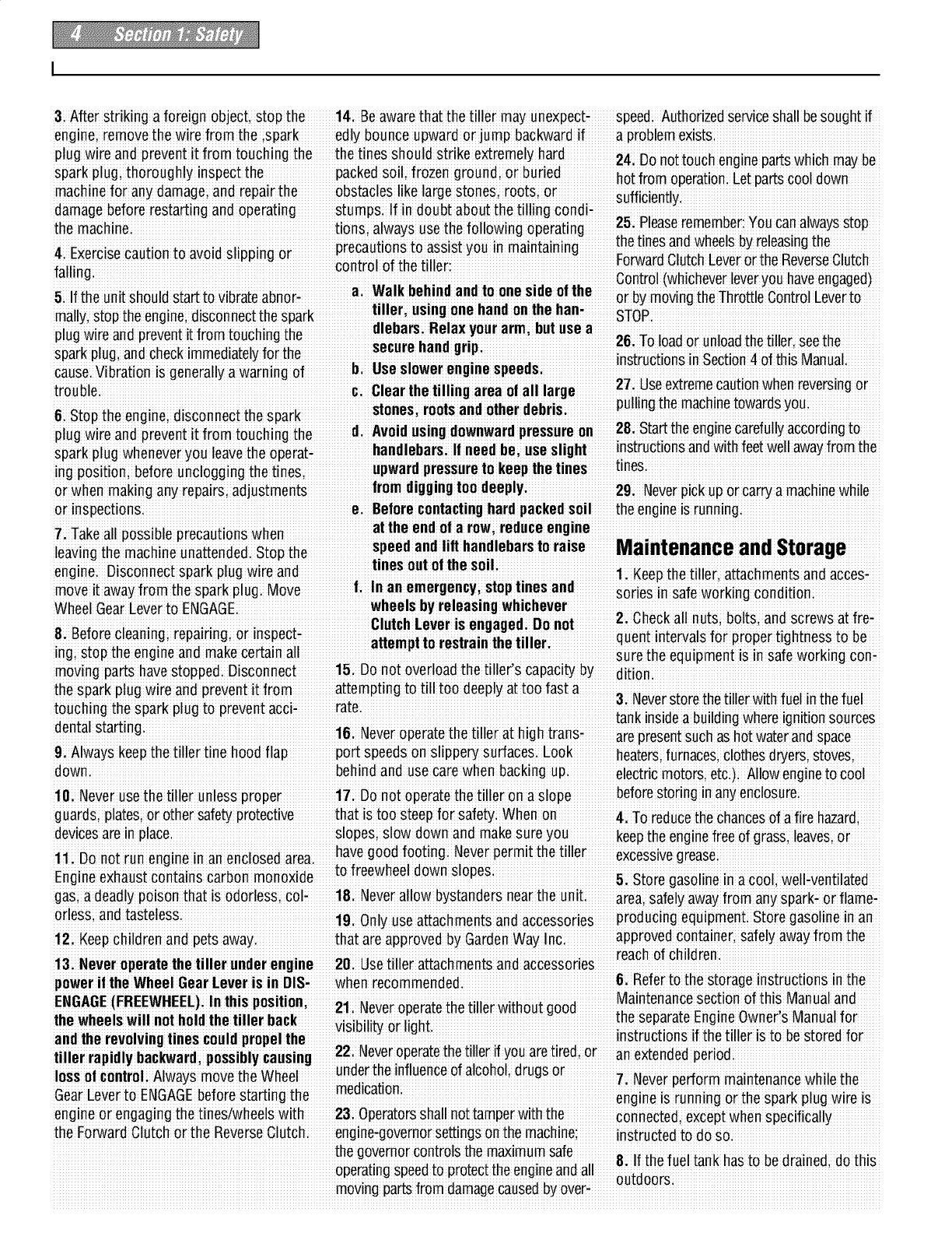
Safety Decals
For yo ur safety and the safe_ of others, Keep the decals €lean and legible at all Refer to the Parts List in thisman ual for
various safetyand operational decalsare times. Contactyour local Service dealer or decal Iocations, part n umbers and order-
located on your unit (see Figure 1-2 the factop¢for replacementsif any decals ing instructions
below)i aredamaged or missing:
Con#ol Descriptions
Tine Warning(on controlPanel)
(on rightside of
hood flap)
Message(on engine)
(ontine hood)
Belts
Warning(on belt cover)
Figure1,2: Locationof Safetyand OperatingDecals
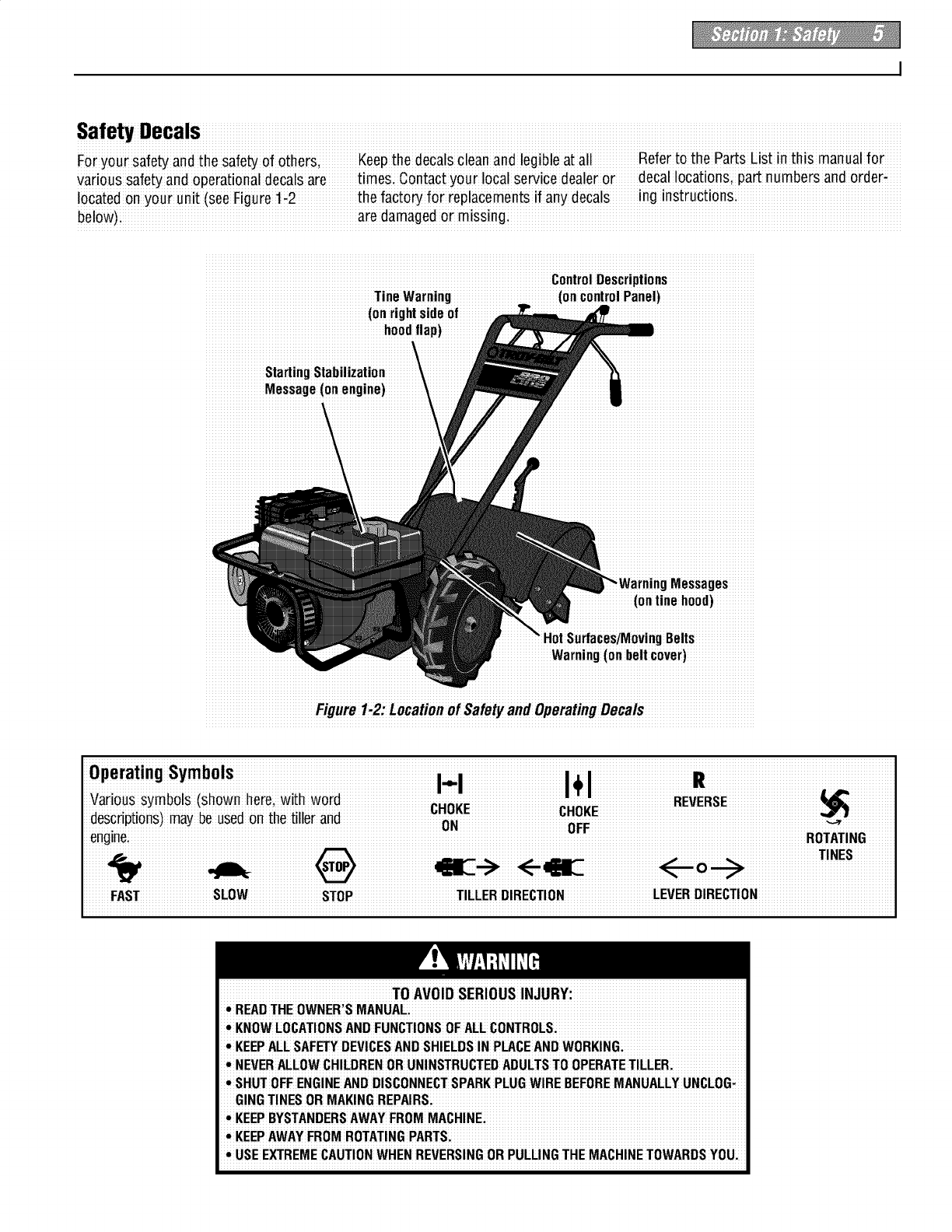
FAST SLOW STOP TILLERDIRECTION LEVERDIRECTION
TO AVOID SERIOUS INJURY:
•READTHE OWNER'SMANUAL
•KNOWLOCATIONSAND FUNCTIONSOFALL CONTROLS:
• KEEPALLSAF_Y DEVICESANDSHIELDSIN PLACEANDWORKING:
•NEVERALLOWCHILDRENOR UNINSTRUCTEDADULTSTOOPERATETILLER.
!•SHUTOFF ENGINEAND DISCONNECTSPARKPLUGWIRE BEFOREMANUALLYUNCLOG_
GING TINES OR MAKINGREPAIRS:
• KEEPBYSTANDERSAWAYFROM MACHINE:
• KEEPAWAYFROM ROTATINGPARTS.
!• USEEXTREMECAUTIONWHENREVERSINGOR PULLINGTHE MACHINETOWARDSYOU;
To prevent personal injury or property
damagei do notstart the engine until aII
assembly steps are complete and you
haveread andunderstandthe safetyand
operatinginstructionsinthis Manual:
INTRODUCTION
Carefullyfollow theseassembly steps to
correctly prepareyour tiller for use. It is
recommendedthat you readthis Section
in its entirety before beginning assembly.
INSPECTUNIT
Inspect the unit and carton for damage
immediately after delivery. Contactthe
carrier (trucking company) if you find or
suspect damage. Inform them of the
damageand request instructions for filing
a claim. To protect your rights, put your
claim in writing and mail a copy to the
carrier within 15 daysafter the unit has
beendelivered. Contactus at the factory if
you needassistance in this matter.
UNPACKINGANDASSEMBLY
INSTRUCTIONS
STEP 1: UNPACKING INSTRUCTIONS
1. Removeany cardboard inserts and
packaging materialfrom the carton.
Removeany staples from the bottom of
the carton and removethe carton.
2. Cutthe large, plastic tie strap that
securesthe transmission tube to the ship-
ping pallet. Leavethe handlebarson top of
the tiller to avoid damaging any cables.
3. A bagwith loose hardware is insidethe
literature envelope. Checkthe contents
againstthe following list and Figure 2-1.
Contactyour local dealer or the factory if
any itemsare missing or damaged.
NOTE: Forelectric start units, a second
hardware bag is located nearthe battery.
4. The tiller is heavy. You should not
attempt to remove it from the shipping
platform until instructed to do so in these
"Assembly" steps.
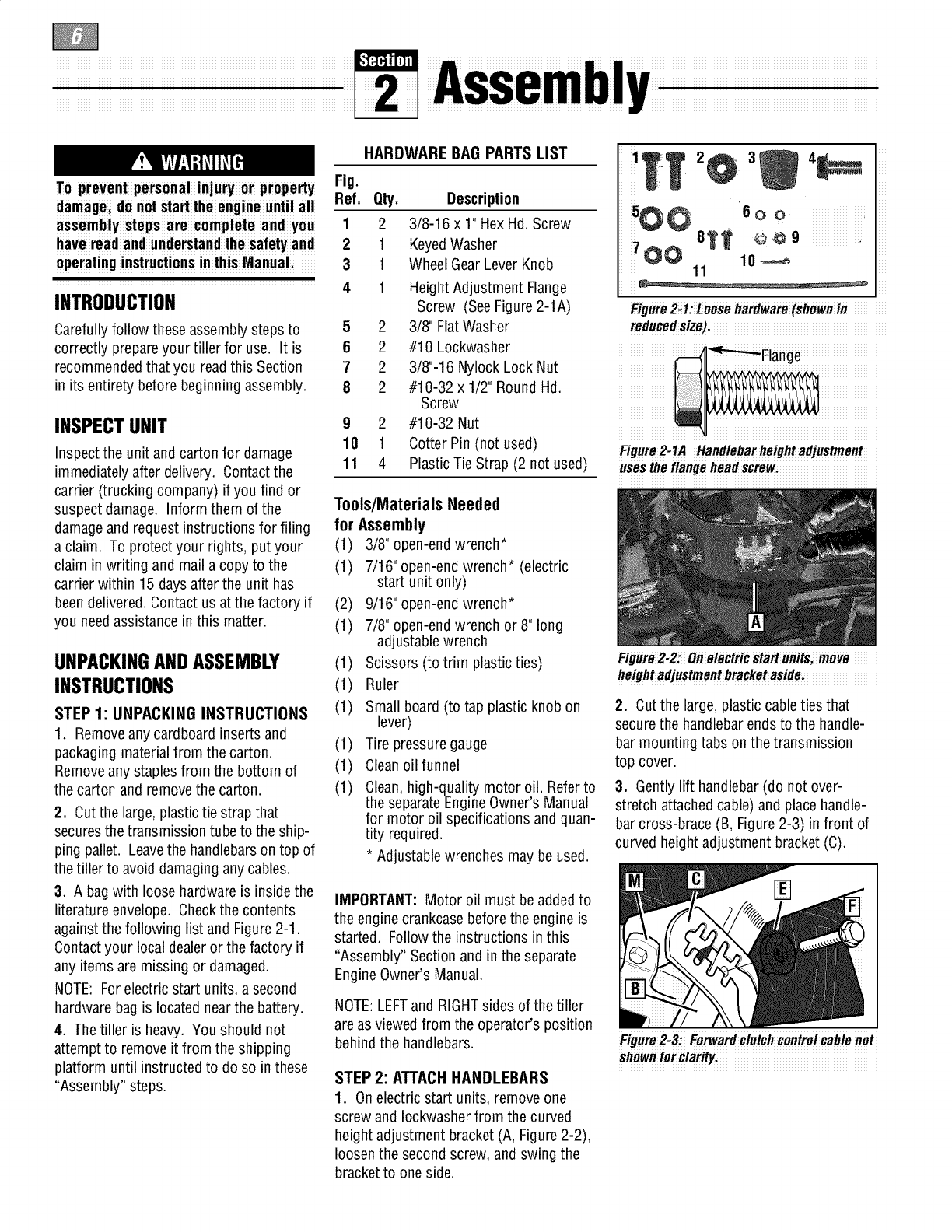
HARDWARE BAG PARTS LIST
Fig.
Ref. Qty. Description
12 3/8-16 x 1" HexHd. Screw
21 KeyedWasher
31 Wheel GearLever Knob
41 HeightAdjustment Flange
Screw (SeeFigure2-1A)
52 3/8" FlatWasher
62#10 Lockwasher
72 3/8"-16 Nylock Lock Nut
82#10-32 x 1/2" Round Hd.
Screw
92#10-32 Nut
10 1 Cotter Pin (not used)
11 4 Plastic Tie Strap (2 not used)
Tools/Materials Needed
for Assembly
(1) 3/8" open-end wrench*
(1) 7/16" open-end wrench* (electric
start unit only)
(2) 9/16" open-endwrench*
(1) 7/8" open-end wrench or 8" long
adjustablewrench
(1) Scissors (to trim plastic ties)
(1) Ruler
(1) Small board (to tap plastic knob on
lever)
(1) Tire pressure gauge
(1) Cleanoilfunnel
(1) Clean,high-quality motor oil. Referto
the separateEngineOwner's Manual
for motor oil specifications and quan-
tity required.
*Adjustablewrenches may be used.
IMPORTANT: Motor oil must beaddedto
the engine crankcasebefore the engine is
started. Followthe instructions in this
"Assembly" Sectionand in the separate
EngineOwner's Manual.
NOTE:LEFTand RIGHTsides of the tiller
areas viewed from the operator's position
behind the handlebars.
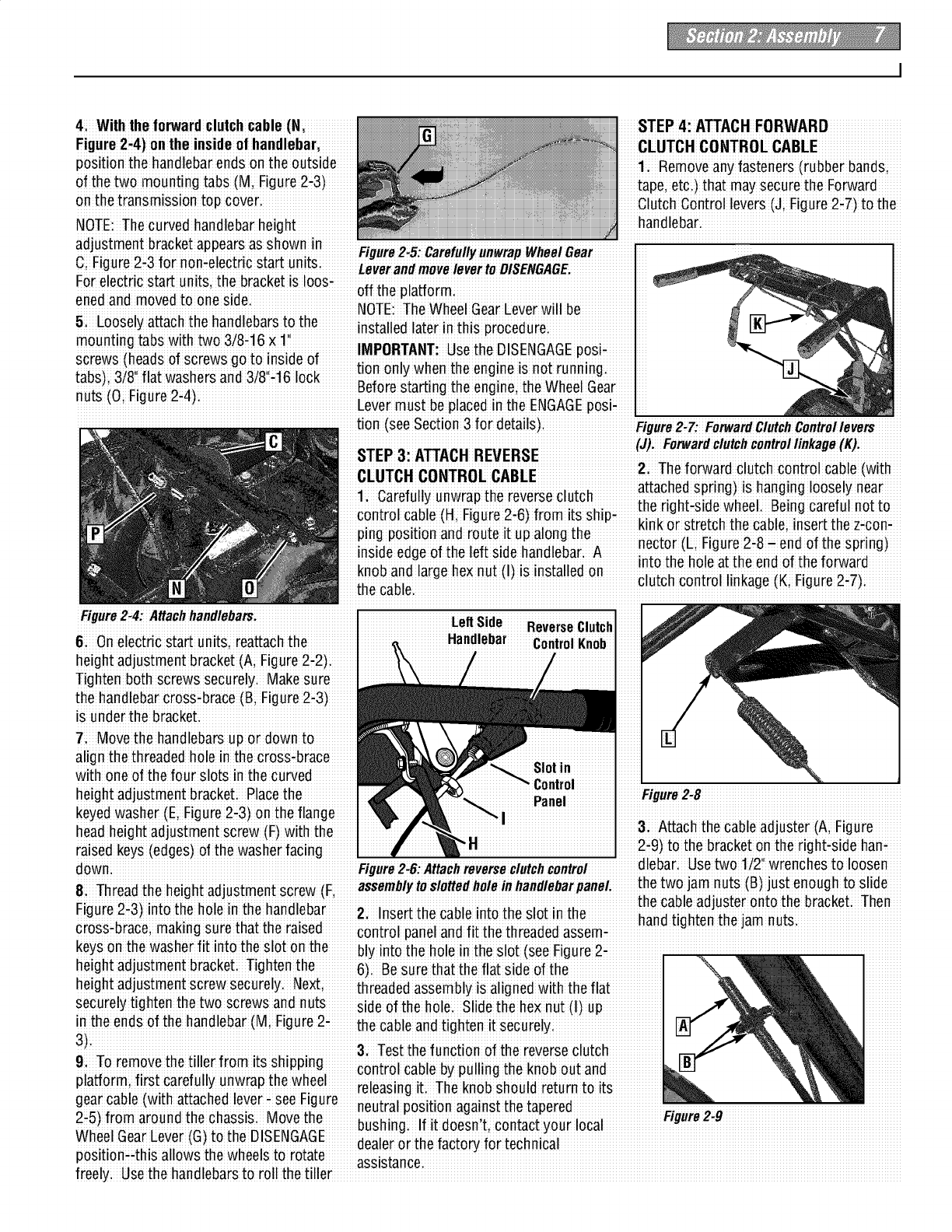
STEP 2: ATTACHHANDLEBARS
1. Onelectric start units, removeone
screw and Iockwasherfrom the curved
height adjustment bracket (A, Figure2-2),
loosen the second screw, and swing the
bracket to oneside.
4_
_iiiiiiiiiiiiiii_ iii
11
iiiiii iii
Figure2-1:Loosehardware(shownin
reducedsize):
Figure 2,1A Handlebarheightadjustment
usestheflange head screwi
Figure 2:2:0n electric start unitsi move
height adjustmentbracket aside:
2. Cut the large, plastic cable ties that
securethe handlebar ends to the handle-
bar mounting tabs on the transmission
top cover.
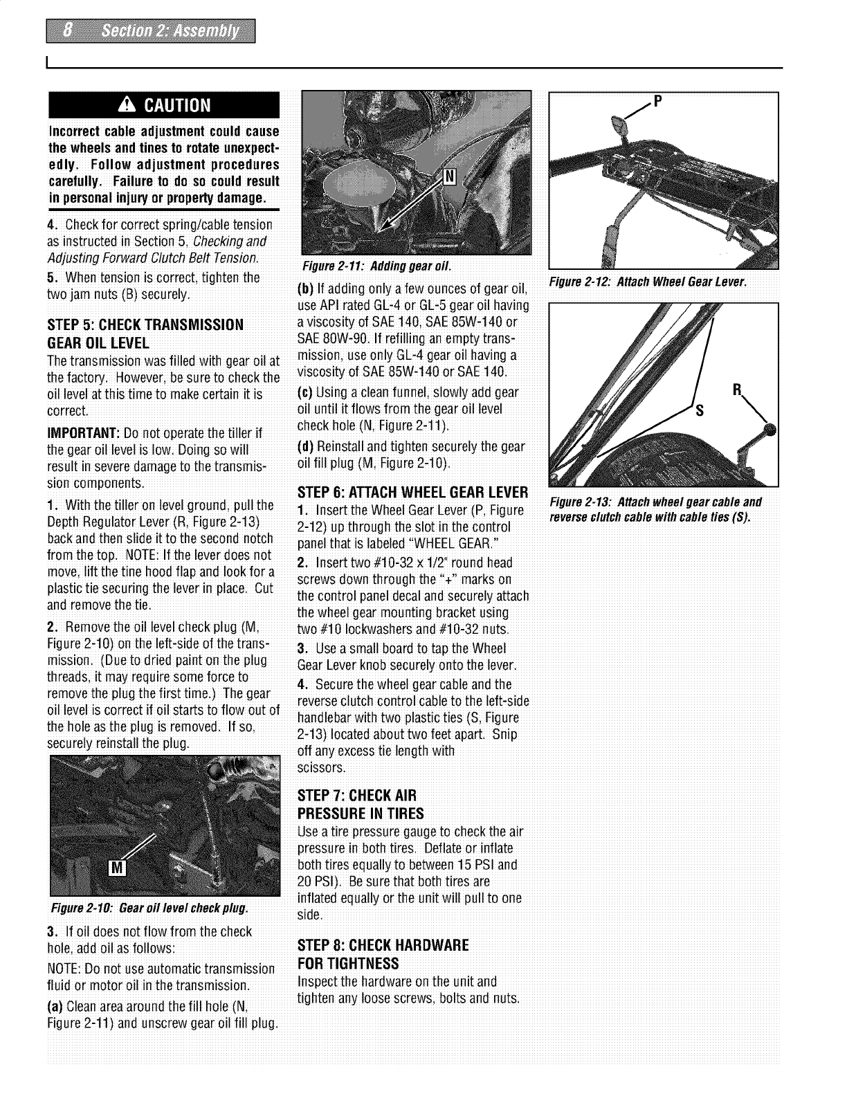
3. Gently lift handlebar(do not over-
stretch attachedcable) and place handle-
bar cross-brace (B, Figure2-3) infront of
curved height adjustment bracket (C).
Figure 2.3: Forwardclutch controicable not
shownforclarity.
4: With the forwardclutchcable (N,
Figure2-4)on the insideof handlebar,
position the handlebarends on the outside
of the two mounting tabs (M, Figure2-3)
onthe transmission top covc
NOTE: The curved handlebar height
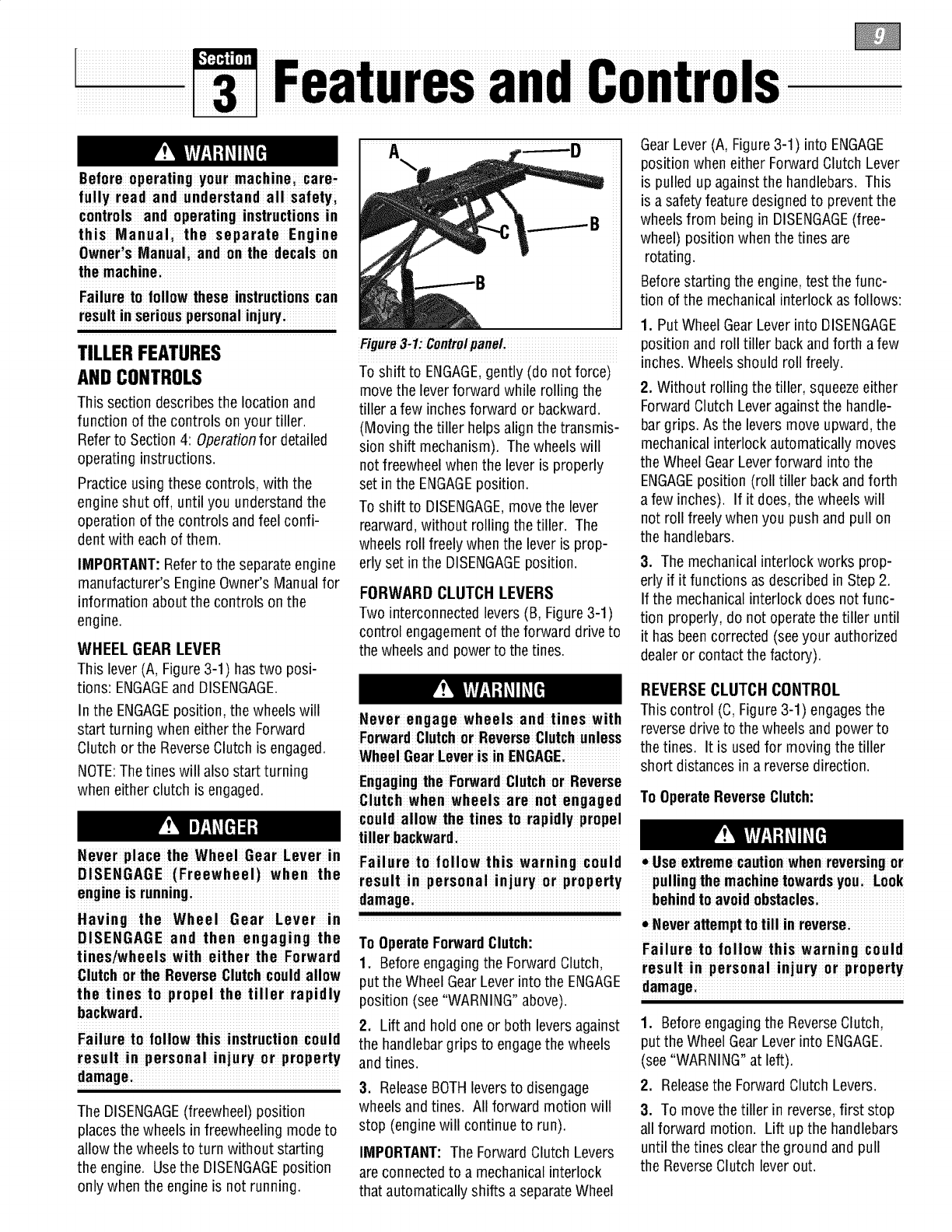
STEP 4: ATTACH FORWARD
CLUTCH CONTROL CABLE
1: Removeany fasteners (rubber bands;
tape, etci) that may securethe Forward
Clutch Control levers (Ji Figure 2-7)to the
handlebari
adjustment bracketappears as shown In Fi..ure2 5: Carefull;unwra"Wheel r
....... _.............................................. ..................... ;................. y_,y p U_a: ..................
C; Figure2i3 for non-electric start un!tSl_everan #moveleverto
Forelectric stag units, the bracket is Ioos-of f the la_oim _
ened and movedto oneside P
' NOTE: The Wheel GearLeverwill be
5i Loosely attach the handlebarsto the installed later in ins p¢oceduie I
mounting tabs with two 3/8#16×1 1 I
i : IMPORTANT' Usethe DISENGAGEposi.
screws (heads of screws go to Inside of :....
_,_ ._0ii _1_ _,_._ _ only when the engineis riot running
tau_.l;,_/o m w<_s,ers<_nao/o!, v,OuK'
,. _i_; ;_ ,, Before starting the engine; the Wheel Gear
,uL_ !ui rluu_ 5i_!' Lever must be placedin the ENGAGEposii
tion (see Section 3 for details). Figure2;7:FetwardClMcfl Controllevers
CLIITCH CONTROL CABLE 2: The forward clUtChcontrol cable (with
control cable (H,F gure2:6)from its Sh i22 _ _i_.2_22_ _2,1 ,u :_
', ;_ kink or s[reLcnthe cal_,eiinset[ [l]e z-con-
ping posll:lOnano rou[e i[ upalong [ne x,x..x; r=xi;, _o _ _.__., xx;i
inslde edgeof the left slde handlebar: A :: :_ ;
isinstalled on 'n[° me no,e al:me eno
the cable, Je(Ki Figuie2i 7)
61 Onelectric start units, reattach the
heightadjustment bracket (A; Figure2-2)
Tighten bothscrews securelyi Makesure
the handlebarcross-brace (B; Figure2-3)
is under the bracket.
7: Movethe handlebars u) or down to
align the threadedhole in the cross-brace
with oneof the four slots in the curved
height adjustment bracket: Placethe
Left Side Reverse Clutch
Handlebar ControlKnob
Slotin
Control Figure2,8
keyedwasher (E Figure2-3)onthe flange
headheight adjustment screw (F) with the 3; Attach the cable adjuster (A; Figure
raised keys (edges)of the washer facing 2-9)to the bracket on the right-side han-
downi Figure2,6:Attach reverseclutch control !n
Thi._ih _h_inhi _rli,mtm_ni _r_w i assemblyto slottedholeinhandlebar the two jam nuts (B} jast enough to slid
Fiour'e2"3: i_o _ hole'_nthe hand eba'r' the Cableadjusteronto the bracket: Then
g-) 2i Insert the cable into the slot in the handti, htenthe iam nuts
crossfbrace; making suie !hat !he raised coniiol paneland fii the threaded assemi
keys onthe washerfit into the slot onthe bly into the hole inthe slot (see Figure2-
heightadjustment bracketi Tightenthe 6)Be sure that the flat side of the
heightadjustment screw securely. Nexti threadedassembly is aligned with the flat
securelytighten thetwo screws and nuts side of the holei Slidethe hexnut (I)up
in the ends of the handlebar(Mi Figure 2- the cable and tighten it securely
3)
9To removethe tiller from its shipp ng control cable by pulhng the knob out and
pla_ormi first carefully unwrap the wheel il in it TI_ h I r t rnt it
...... eeas g. e obs cud eu o s
gear cable (wzth attached lever, see Rgure :i : r
...... ...... .... neutral posit on againstthe tape ed .................................................................................
2:5) from aroundthe chassis Movethe :. Figure 2_9
_,,7 ;" _.Z_C2_.._ bushingi If It doesnt, contactyour local
wnee bear Lever_Ll_:omeu_l:i'_L1ALll: ir it h f t f r t hni I
.;idea e oe ac o_ oec ca
pos!t!oni4h!s allows the wheels to rotate assistance'
freely;Use the handlebars to roll the tiller
Incorrect cable adjustment couId cause
the wheels andtines to rotate unexpect-
edlyi Follow adjustment procedures
carefullyi Failure to do so could result
in personal inlu_ or prope_ damage.
4Checkfor correct spring/cable tension
aSinstructedinSection5;Checkingand
Adjusting ForwardClutchBelt Tension. ,,, ..., __ ,,_,,, .,,, ,., ..
5. Whentension is correct; tighten the Figure2.12: AttachWfleei Gear Lever
two iam nuts (B_securely (b)If adding only a few ounces of gear oil
_ uSeAP iaied GLi4 oi GEi5geai oil hav ng
STEP 5: CHECKTRANSMISSION a viscosity of SAE 140; SAE85W,140 or
• : mission use only GL,4 gear oil having a...........
Thetransmiss!on was f!lled w!th gearo!l at. i., k,; _;:
VISOOSll:yOf hAL UbVV14U or bat: ]qU
the factoryi However;besure to check the-
oil levelat th is time to makecertainit is (c)Usi ng a cleanfunnel; slowly add gear R
correct, oil until it flows from the gear oil level i
IMPORTANTiDo noi oieraie i heiiller if checkh ole(N, Figure 2-11)
the gear oil levelis Iowi going so will (d) Reinstalland tighten securely thegear
iesuli in seveie damageto the transmisi oil fill plug (Mi Figure2-1 O)
sloncomponents. STEP 6: ATTACHWHEEL GEARLEVER
nIvIr n Ilth Figure2 13 Attachwheelgear cable and
1 With the tiller o e egou d;pu '
1, Insert the Wheel GearLever (Pi Figure i.i.
v r " r utchcablewlthcab eties(S).
DepthRegulatorLe (R, F!gu e 2,12)up through the slot !n thecontrol
backand then slide it to the second notch .....
: panel that is labeled WHEELGEA&
.fromthe mp NOTP If the rover does _i_ _C _}_i _X,_
:1 ..' i'. Insert two#_U-o/x UZ round Ilead
move, h.fttne tlne hOOdflap ano lOOK.foraii _..#X
i screwsdown through the irl_o M,,
plastic tlesecurlngtheeverlnplac Cut th cntil ne I nd e reI tt h
_:.:.'e _o o pa e _aa scu ya ac
and removeme _mi ihe wheel geai mouniing biacket using
2i Removethe oil levelCheckplug (M; two #t0 Iockwashersand #10:32 nutS:
Figure2-10)on the left-side of the trans-3 Used small board to tad theWheel
mission. (Due io dried paint onihe plug Gear Lever knobsecurely onto the levei.
threads it may require some forceto
..... ...... 4Secure the wheel gearcable and the
removethe plug the first time )The gear
: :i reverseclutch control cable to the left-side
011level is correc[ i.f Oll sEar[s £o TIOWOU£01" ;.-
_i; _ ,._; _i; _ nanaleoarWl1:nl:woplasl:lCl:les i-igure
then°iea_tu_piuui_'em°veu "Su' 2 1 Itd ottw let _
. ' -3) oca eab u o eapa 4S p
securely reinstall the plug' off any excesstie length with
SClSSOrS_
STEP 7: CHECKAIR
PRESSURE IN TIRES
Useatire pressuregauge to check theair
pressurein both tire& Deflate or inflate
both tires equally to between15PSI and
20 PSI)i Be sure that both tires are
,,,inflated equally or the unit will pull to one
I-#gurez-Tu: _earo# mve#cnecKpmgi sidei
3; If oil does not flow from the check
fluid or motor oil inthe transmissioni Inspect the hardwareon the unit and
Li _'_ _ _i _ ;_ _iiiL_i_ tighten any loose Screws;bolts and nuts
(a] umanareaaround _ne fin Ilo_e tin,
Figure2,11)and unscrew gear Oilfill plug:
Before operating your machinei care,
fully read and understand all safetyi
controls and operating instructions in
this Manual, the separate Engine
Owner,s Manuali and on the decals on
the machinei
Failure to follow these instructionscan
resultin seriouspersonalinjury,
TILLERFEATURES
AND CONTROLS
This section describesthe location and
function of the controls on your tiller.
Referto Section4: Operationfor detailed
operating instructions.
Practice using these controls, with the
engine shut off, until you understand the
operation of the controls and feel confi-
dent with each of them.
IMPORTANT:Referto the separateengine
manufacturer's EngineOwner's Manualfor
information about the controls on the
engine.
WHEEL GEAR LEVER
This lever (A, Figure 3-1) has two posi-
tions: ENGAGEand DISENGAGE.
Figure3-1:ControipaneL
To shift to ENGAGE,gently (do not force)
movethe leverforward while rolling the
tiller a few inchesforward or backward.
(Moving the tiller helps align the transmis-
sion shift mechanism). The wheels will
not freewheel when the lever is properly
set in the ENGAGEposition.
To shift to DISENGAGE,movethe lever
rearward,without rolling the tiller. The
wheels roll freely when the lever is prop-
erly set in the DISENGAGEposition.
FORWARD CLUTCH LEVERS
Two interconnected levers(B, Figure 3-1)
control engagementof the forward drive to
the wheelsand power to the tines.
In the ENGAGEposition, the wheels will
start turning when either the Forward
Clutch or the ReverseClutch is engaged.
NOTE:The tines will also start turning
when either clutch is engaged.
Never engage wheels and tines with
ForwardClutchor Reverse Clutchunless
Wheel Gear Leveris in ENGAGE:
Engagingthe Forward CIutch or Reverse
Clutch when wheelsarenotengaged
could allow the tines to rapidly propel
tiller backward.
Never place the Wheel Gear Lever in F il r III w hi w rnin I
a u eto o o t s a gcou d
DISENGAGE (Freewheel) when the result in personal injury or property
engme is running, damage
!
Having the Wheel Gear Lever in
DISENGAGE and then engaging the
tines/whe els with eithe r the Forward
Clutchor the ReverseCIutchcouId allow
the tines to propel the tiller rapidly
hac_ard:
Failure to fol low thisi nstruction couId
result in personal injury or property
damagei
The DISENGAGE(freewheel) position
placesthe wheels in freewheeling mode to
allow the wheels to turn without starting
the engine. Usethe DISENGAGEposition
only when the engine is not running.
To OperateForwardClutch:
1. Before engagingthe Forward Clutch,
put the Wheel GearLever intothe ENGAGE
position (see "WARNING"above).
2. Lift and hold one or both leversagainst
the handlebargrips to engagethe wheels
and tines.
3. ReleaseBOTHleversto disengage
wheels and tines. All forward motion will
stop (enginewill continue to run).
IMPORTANT: The Forward Clutch Levers
are connected to a mechanical interlock
that automatically shifts a separateWheel
GearLever (A, Figure 3-1) into ENGAGE
position when either ForwardClutch Lever
is pulled up against the handlebars. This
is a safety feature designedto prevent the
wheelsfrom being in DISENGAGE(free-
wheel) position when the tines are
rotating.
Beforestarting the engine, test the func-
tion of the mechanical interlock as follows:
1. Put Wheel GearLever into DISENGAGE
position and roll tiller backandforth a few
inches. Wheelsshould roll freely.
2. Without rolling the tiller, squeezeeither
ForwardClutch Leveragainst the handle-
bargrips. As the levers move upward, the
mechanicalinterlock automatically moves
the Wheel GearLeverforward into the
ENGAGEposition (roll tiller back andforth
a few inches). If it does, the wheels will
not roll freely when you push and pull on
the handlebars.
3. The mechanical interlock works prop-
erly if it functions as described in Step 2.
If the mechanical interlock does not func-
tion properly, do not operate the tiller until
it has beencorrected (seeyour authorized
dealer or contact the factory).
REVERSECLUTCH CONTROL
This control (C, Figure3-1) engagesthe
reversedrive to the wheels and power to
the tines. It is usedfor moving the tiller
short distances in a reversedirection.
To OperateReverseClutch:
• Use extremecautionwhen reversingor
pulling the machinetowardsyou Look
behindto avoid obstaclesi
• Neverattemptto till in reversei
Failure to follow this warning could
result in personal injury or property
damagei
1. Beforeengaging the ReverseClutch,
put the Wheel GearLever into ENGAGE.
(see"WARNING"at left).
2. Releasethe ForwardClutch Levers.
3. To move the tiller in reverse,first stop
all forward motion. Lift up the handlebars
until the tines clear the ground and pull
the ReverseClutch lever out.
Thewheelswillrotateinareversedirec-
tionaslongastheleverisheldin
REVERSE.Tostopthewheelsandtines,
releasetheleveranditwillreturnto
NEUTRAL.Neverattempt to till while
movingin reversedirection.
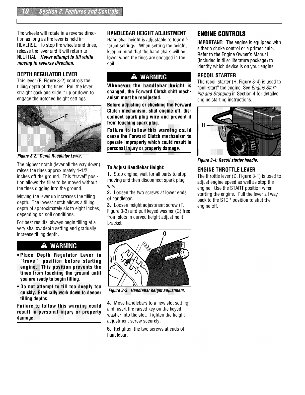
DEPTH REGULATOR LEVER
This lever (E, Figure3-2) controls the
tilling depth of the tines. Pull the lever
straight backand slide it up or down to
engagethe notched height settings.
Figure3-2: Depth RegulatorLever:
The highest notch (lever all the way down)
raisesthe tines approximately 1-1/2
inches off the ground. This "travel" posi-
tion allows the tiller to be moved without
the tines digging into the ground.
Moving the lever up increasesthe tilling
depth. The lowest notch allows atilling
depth of approximately six to eight inches,
depending on soil conditions.
For best results, always begin tilling at a
very shallow depth setting and gradually
increasetilling depth.
HANDLEBAR HEIGHT ADJUSTMENT
Handlebar height is adjustableto four dif-
ferent settings. When setting the height,
keep in mind that the handlebars will be
lower when the tines are engagedinthe
soil.
ENGINECONTROLS
IMPORTANT:The engine is equippedwith
either a choke control or a primer bulb.
Referto the EngineOwner's Manual
(included intiller literature package)to
identifywhich deviceis on your engine.
Whenever the handlebar height is
changed,the ForwardClutchshift mech,
anismmustbe readjusted:
Beforeadjustingor checkingthe Forward
Clutchmechanismishut engine oil dis,
connect spark plug wire and prevent it
fromtouchingsparkplug:
Failureto follow this warning could
causethe Forward Clutchmechanismto
operate improperlywhich could result in
personalinjuryor prope_y damagei
Figure3_4:Recoilstarterhandle:
To AdjustHandlebarHeight:
1. Stop engine, wait for all parts to stop
moving and then disconnect spark plug
wire.
2. Loosen the two screws at lower ends
of handlebar.
3. Loosen height adjustment screw (F,
Figure3-3) and pull keyedwasher (G) free
from slots incurved height adjustment
bracket.
RECOIL STARTER
The recoil starter (H, Figure 3-4) is used to
"pull-start" the engine. SeeEngineStart-
ing and Stopping in Section 4 for detailed
engine starting instructions.
ENGINE THROTTLE LEVER
The throttle lever (D, Figure 3-1) is used to
adjust enginespeed as well as stop the
engine. Usethe STARTposition when
starting the engine. Pullthe lever all way
backto the STOPposition to shut the
engine off.
G
• Place Depth Regulator Lever in
iltraveli' position before starting
enginei This position prevents the
tines from touching the ground until
youare readyto begintilling;
• Do not attempt to tilltoo deeplytoo
quicklyiGradually work downto deeper
tilling depthsi
Failureto follow this warning could
result in personal injury or property
damagei
Figure3_3!Handlebarheightadjustment!
4. Move handlebars to a new slot setting
and insert the raised keyon the keyed
washer into the slot. Tighten the height
adjustment screw securely.
5. Retighten the two screws at ends of
handlebar.
Thr ReverseClutchControl
Beforeoperating your machinei carefull!
read and understandalI safety (Section
1), controls(Sect ion 3) and operating
instructions (Section 4) in this Manual
in the separate EngineOwner's Manual Recoil
and onthe decalson the machine: Starter
Failure to follow these instructions can
resuIt in seriouspersonalin]ury
DepthRegulatorLever
INTRODUCTION
Readthis Section of the manualthor
oughly before you start the engine. Then,
take time to familiarize yourself with the _
basic o Fit
Find an open; levelarea and practice using
the tiller controls without engaging the
tines in the soil (put tines in "traver' FJ ,re4.1
Setting)i Only after'you've become com-
pletely uardSand covers
begin using it in the garden, are m place
.r,r_,s i...r..-,-,.. 4i Checkair cleanei and engine cooling To help prevent serious personalinju_
Dnz:MA-II_ urEn_llu. System. See EngineOwner's Manual. or damagetoequipment:
venorm 1:neTonowmgmalm:enanceeunn0 _. Belore startin" endne "ut Wheel Gear
th_ first hm,r_ _f n_w _,r_ti_n (_, _; _e!ec_a xorwaroDe!_speeo range _see u u
Secti_5_Maintenanceandt'he mai'niei ChangingBelt SpeedRangesin this. _e_erintoE:GAGEiP_sitionFrw r :1 ih
noncesection ofihe Engine Owneris Secti°n) L:[,°erresSZanr__eev_U_c_°C_rt_o_ ui_Cto
Manual)
ineutral(disengaged)positionsby releasi
STARTING AND STOPPING ENGINE
the operatinginstructionsinthis Section: and safetyrules carefully
Control&li Oomple!e!he PreiStartChecklist. 5: If the engine isequipped with a fuel
:::: 2:Put the Wheel GearLever (Figure 4-1)shutoff Valve;turn the valve to the open
re,atan L;neCKB_SZ nto the ENGAGEposit oni positioni as instructed in the separate
eDn°4hnef° I°win! bef°re star!ing !he & Putthe Depih Regulatoi Eeverinto the EngineOwnerls Manua
'iiiavelii position (levei all the way downi 6. Moveihe Engine Thiottle Eeveiinto the
1 Check unit fo r loose or missing hardi Sothat the tines are clear of the groundi STARTposition:
ware. Service as r.equired. 4. Releaseall conirols on ihe tillei 7. Chokeoi prime ihe engine as instiucted
2 Check motor oll level SeeEngme Rnth rt En in wn r' M n I
...... ...... esepaia!e! igiieO ie s !aiaa!.
Owner'sManual.
8: Checkbehind you to avoid contacting
any obstacles when pulling the starter
rope: Place onehand on the fuel tank to Bo net
stabilize the unit and usethe recoil starter try to make the tiller till mere deeply.
Engine Owner'sManualiWhen the eng!ne the tiller back and can aIlowthe tines
9:Use the FASTthrottle speed setting (b) ASthe tiller moves forward;relax and
'°i
toppmg ,.i behi,dwhe,mevtuOtureverse.
Stopthe wheelsand tines, release allel e 1:oone sloe o!me tll!eri use a
the Forward Clutch leversor SheReverse light but secure grip wish one hand 6To turnShe tiller around;
Clutch Coniiol (whichever control is in onthe handlebars;but keep your (a) Practiceturning in a le_eli openareai
use) aim loose SeeFiguie 4i2. Let She Beve_ careful to keep your feet and
tiller move aheadat its own pace. lensaway from the tines
zi!o sl:opl:ne engine;movel:ne Lng!ne nX ._...; ;_ _X;. X_.._X
Throttle Leverinto the STOPposiSiom _..u_uuL_._.uu_, _,i,_,_,_,_l_u_ (b)To s!art a [urm reducethe engine
........................................................................................................._uL,y _.u .u,_,__._ _,,,_,_uu,u...................................ed nd then lift th h ndl r ........
spe a e a eba
deeper this takes weight off the
OPERATINGTILLER , ]-, ; .; I i until the engine andiines are bali
wneels reouces[rac[ion anecauses anced over the wheels (Fioure4 4_
the Sinesto ir¥ and piope the S er _ "J
Before tilling; contactyour telephone or
utilities company and inquire i!
undergroundequipment or lines are on
The following pages provideguidelines to
usingyou rtiller effectively and safely in
Various gardening applicationsi Besureto
read Tilling Tips& Techniquesin this
Sectionbefore you actually put the tines
intothe soil Figure4_4: Findbalancepointbefore
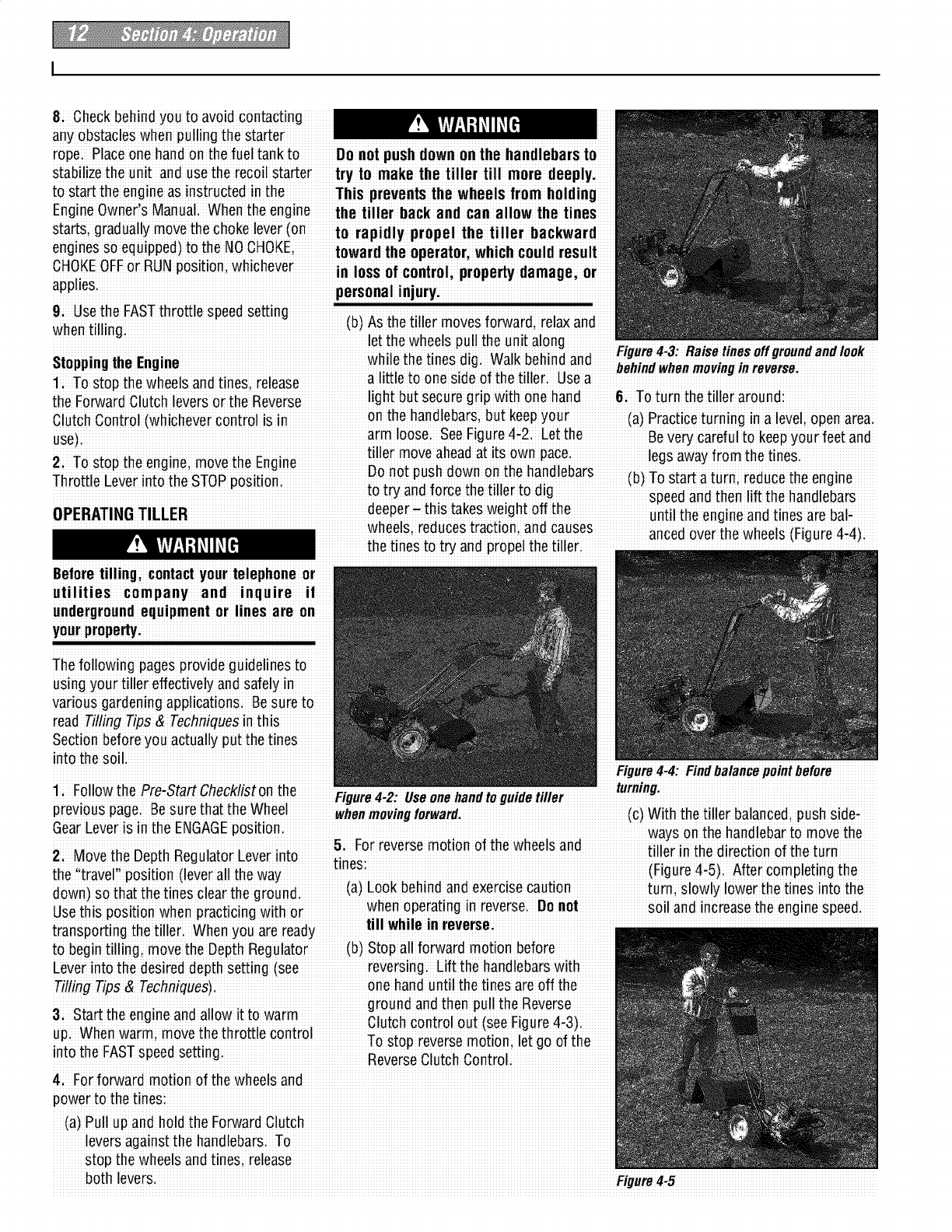
li Followthe Pre-Start Check/iston the 'Fiuure4 2_ Useonehandto"uide tiller turning:
y"_ y
previous page Besure that the Wheel r
iwhenmovingfeiwa_: (c) With the tiller balanced,push side-
GearLever is inthe ENGAGEposition • _ ways on the handlebarto move the
& L°r reverse m°n°n °f tile wlleels and tiller in ih" _ii"_ti_n Xf th_ i rn
2i Move the DepthRegulatorLever into Sin _u _' "
.... es
the travel position (leverall the way i (Figure4i5)i After completing the
o a e esfi ea e (a)Look behind and exercisecaution turn;slowly lower'the tines into the
down)s_ th__tth_ t!ne_el_ortheoround;
s thi.........sitinwhn r tiin wish r wnen°peradnginreverse u°n°l soil and increasethe engine speed
U e spo o e p ac c g o i,, _
IIII w1111eiii reverse
to begintill ingi move the DepthRegulator (b)Stop all forward motion before
Leverinto the desireddepth Setting (See reversing. Lift the handlebarswith
TilfingTios & Techniques) one handuntil the tines are off the
ground andthen pull the ReVerse
3i Sta_ the engine and allow it to warm Clutch control out isee Fin ie 4
up When warm; movethe throttle control
: : TOstop reverse motloni let go of the
In[o me rA_ speeoseeing i ReverSeClutch Control.
4:For forward motion of the wheels and
power to the tines:
(a) Pullup andhold the ForwardClutch
leversagainst the handlebarS: To
stop the wheels andtines; release
both levers: Figure4_5
Stoppingthe Tiller and Engine NOTE:If the belt is difficult to move, pull
1. To stop the wheels and tinesi release on the engine start rope while pushing the
the Forward Clutch levers or the Reverse belt with _our finger (enginedrive pulley
Clutch Control (whichever is engaged): will turnas start ropeispulled)
2. To stop the engine;move the Engine 6. Checkthat the beltis within theforward
Throttle Lever to STOPi belt guide (E Figures 4-10 and 4-11)on
the right,side of the unit and is within the
3, If the engine is equipped with a fuel .......
• forward _dler(Fi Rgure 4q t) Onthe left, .......
shutoff valvei close the valve as instructed :
_,, ,.. side Be sure that the belt issituated in
in me Engineuwner s lvlanual.
.......................................................................................the center grooves (C and Di F!gure4-1O)
oftheem :upper) and transmission
engine;wait for all parts to stopmovingi 7i Reinstall the plastic belt cover and
let engine cool and disconnect spark secure itwith the two nuts
plug !i 8, Put Wheel GearLever in ENGAGEand
Failure tolollow these instructionscould reconnect sparkplug wire beforeattemptiFigu re4i11: Topviewofforwarddrivepulley
result in personalinjuryi ingto start the engine. SYstem(engineis atleftisideof view):
To Changefrom Highto Low Speed: 2i Put Wheel GearLever inDISENGAGEi
CHANGING BELTRANGE SPEEDS 1.StoR the engine, allow itto cool; and 3Remove the iwo nuis fiom the plastic
The iiller hastwo foiward belt iange disconnecithe spaik plug wire. b_li co,/ei on io; oi the tiansmission
Speedsfor the wheels and tines; L°w and removethe belt coveri
"i '
TOrware orlve Dell o U[OT l:ne l:rans mission
sets of grooves on the forward drive pulley
and thetransmission drive Rulley
NOTE: The High speed belt range is rec-
ommended fo rail tillingp urposes; The
Low speed belt range will operate thetines
and wheelsat a slower forward speed;
which may be suitable in someco nditions
(such as tilling inve_h ardg round)
ToChangefrom Lowto High Speed:
1. Stop the enginei allow it to cool; and
disconnectthe spark Rlug wire:
2. Movethe Wheel GearLever into the
DISENGAGEposition.
3. Removethe two nuts from the plastic
belt cover on top of the transmission and
removethe belt cover
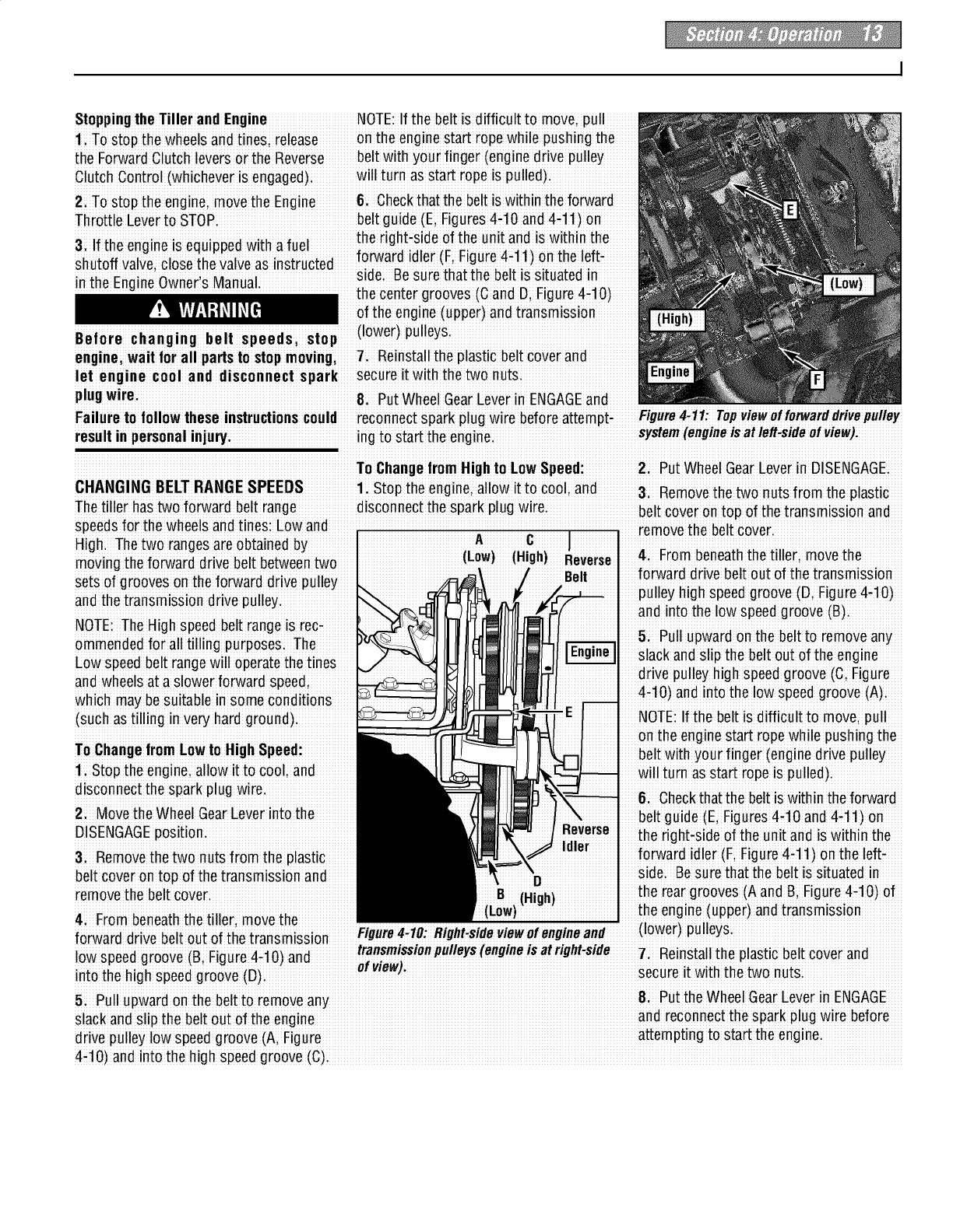
4: From beneath the tiller;move the
Idler
iD
(High)
pulley high speed groove (D, Figure 4-1O)
and into the low speed groove (B);
5: Pull upward on the belt to removeany
slack and slip the belt out of the engine
d rive puIleybig hspeedg roove (C,Figure
4-t0) and into the low speed groove (A)i
NOTE:If the belt is difficult to move; pull
on the engine start rope while pushing the
belt with your finger (enginedriveRulley
will turn as start rope is pulled)i
6: Checkthat the belt iswithin the forward
belt guide (E, Figures4-10 and 4-11) on
the right-side of the unit and is within the
forward idler (Fi Figure 4-11) on the left-
side: Besure that the belt is situated in
the reargrooves (A and&Figure 4i10) of
the engine (uppeO andtransmission
)pulleys;
forward drive belt out of the transmission
low speed gioove (Bi Fig_ie4il O)and transmissionpulleys(engineisat righttside 7Reinsiall the plastic belt cover and
into the high speed groo#e(D)"'_'1 secureit with the two nuts
5: Pull upward on the beltto removeany 84 Put the Wheel GearLever in ENGAGE
Slackandslip the beltout of the engine and reconnect the spark plug wire before
drive pulley ow speedgroove (A, F gure attempting !o Startthe engine.
4-10) and into the high speed groove(C),
TILLING TIPS &TECH NIQUES,
*Thisis a CRT(co uniei-r0tating ii ne) iille r. As the wheels pull _Whencultivatin g(b reaking up sufface soil around plan!s to
forward,the tines rotatebaCkWardThiscreatesan" uppercutlltine destroy weedsi see Figure 4-9); adjust the ti nes to digo nly
action which digs deeply;upioo_ingsoil and Weeds Donlt oveP !? _o27deep.Using shallow !illing depthshelps preventinjury
10ad_heenginei but dig as deeply as possible0n ea0hpass Ont0plantswhose[oo!s0ftengro_cl0set0thesurface If
late_passes,the Wheelsmay _endto spin in the soft di_t. Help needed;lfft up on the handleba!s sligh!ly to prevent !he lines
them along by liftingup slightly 0n the handleba[(one handipalm from digging !oo deeply (Cultivatingon a regular basis elimi-
upiworks most easily), na!esweeds,and loosens and aera!esthe soil _or be!ter mois-
ture abso[ption andfaster plant growth)
*Avoid the temptati0n to push down 0n the handlebars in an
attemptto forCethe tiller to dig deeper Doing s0 takesthe wei.ght *Waterng_hegardenareaafewdayspror_ot ngw make
off the poweredWheelsiCausingthereto lose traction Withoutthe tilling easier as will lettingthe newlyworkedsoil setfor a day or
Wheelsto hold the tiller back, the _ineswill attempt _opropel the two bef0remakinga final deeptilling pass
tiller backward,towards the operat0r. (Sometimesislight down-
ward pressureon the handlebarswill helpget through a partiCu-
larlytough section of sod or unbrokengroundi but in most cases
this won't be neCeSsary:)
__i_!!!I WituhreX_eience' Y°Uwill find the "just right" tilling depthandtilling speedc°mbinati°n that is bestf°r
Set the enginethrottle lever at aspeedto give the engineadequatepowerandyetallow it to operateat the slowestpossiblespeedi,at least
until you haveachievedthe maximum tilling depth you desirei Faster enginespeedsmaybedesirable when makingfi nal passesthrough
the seedbedor whencultivatinc.Select!onOf_hecorrect eng!nespeed,!n relation to the tilling depthi will ensurea sufficient powerleveltO
do the job without causingtheenginetOlabori
While tilling, relax and let the wheelspull Wheneverpossbe wakontheunt ed T ngwetso oftenresuts n arge hard
th etille ralo ngwhile thetinesdot he side of the unit to avoid making footprints clumps of soil that can interferewith plant-
digging. Walk on the side that is not _et in your freshly tilled or culti_ated soil. ing If time permits,wait a day or tw0 after
finished(to avoid making footprints in the FootprintsCausesoil COmpactionthat can. heavyrains to allow the soil to dry before
fleshly tilled soil) and lightly, but securely hamper root penetrationand contribute to. tilling. Test soil by squeezingit into aball.
g !p the handlebarw!th fust onehand. . so!ler0s!0ni They can also Plant If !t c0mpressestoo eas!lyi !t !stoo wet t0
unwanted weed seeds back into the till.
I freshly tilled ground. I
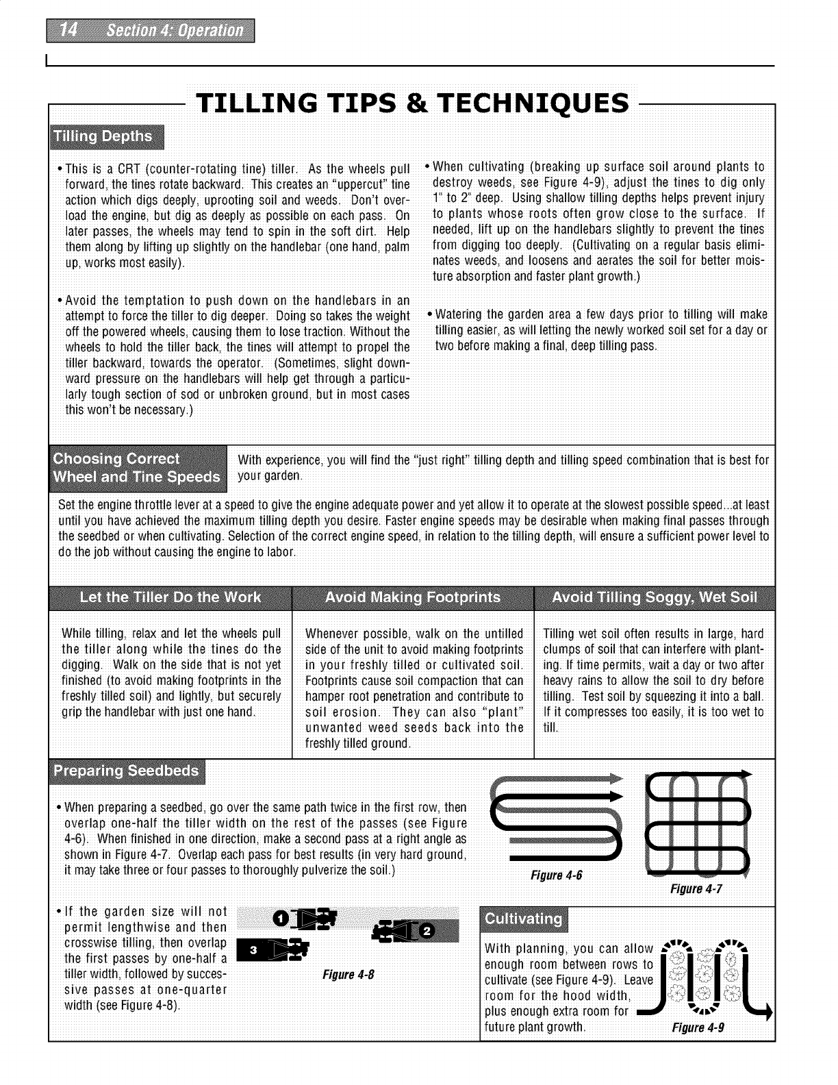
! Whenp!eparing a seedbed go over the samepathtwice in the first row !hen 1
overlap one-half the tille[ Width on !he !est of !he passes (see Figu[e _'
4-6) Whenfinished in onedirec!ioni makea secondpassa! a !ight angleas _ )
shownin Figure4-7. Overlapeachpassfo[ bestresults (in Veryha[d g[oundi .......................................
t maytake!hiee or foui passesto t"oioughly pulverizethesoil!'
Figure 4-7
future plant growth Figure4-9
icont.
callyona slope allows maximum plan_ingarea and also leaves" To minimizesoil erosion,addenough organic mat!erto the soil !o[
room foi cultivating good moisture'holding texturei and avoid leaving footprints o[
wheelmarks.
IMPORTANT' Whent ngons0pes mantanCorrectmotoro
level(check eveiy one'half hour oi opeiation)The slope incline i When tilling Verticallyi try te makethe first pass uphill (!he !ille[
causesih ili I nt w fr mii n rm Ilvlwhi try digs more deeplygoing uphill than it does downhill)In soft soil
eo osa a ay e s o a e e c ca sa e .....
engine partsof lubrication Keepthemotor oil levelat theMI or weeds;:_oumayhave_oi!i_ the:han.dlebarsslight!_ while going
at all timesi upn! .vvnen going aownn! ,eve(ap [ne r!{st passBy aeeu_one_
half the width of the tiller.
Thetines have a self-clearingactiOnwhich elimihatesmost tangling of debris in the tines:
Howeveri occasionally dry grassi stringy stalks or tough vines may becometangled:
Followthese proceduresto helpavoidtangling andto cleanthetines,
To reduce tanghng;set the depth regulator deep enough to get maxmum chopp!ng
action as the tines chop the matefial against the g[ound Ais0; try to till under crop
residuesor cover cropswhile theyaregreen,moist andtender.
, Whiletilling; try swaying the handlebarsfrom side t0 side (about6'ito 12 )This fishtail-
ing" actionoftenClearsthe tinesor debris
•If tangling occurs; lift the tines out Of the soilandrunthe tiller in re_erse (if unit is
equippedwith powered reverse)for a few feet This reversing action of thetines should ............................................................................................
unwind most of thedebris:
• It ma_ be necessary!o iemove the debris by hand (a pocketknife will help you !o cut
awaythe material). Stop the engineand disconnectthe spark plug wire beforeclearing
the tinesby hand.
Before clearingthe tines by handistop
the engineiallow allmoving parts to
stop and disconnect the spark plug
wire:Remove the iqnition keyon elec-
tric start models: Failure to follow
this warning could result in personal
InJU_
LOADINGAN DUN LOADING TILLER •Use Sturdy ramps and manually (engine- When goingu pthe ramps, Stand in the
shut off1 roll the tiller into and out of the no_mal operating PoSition and push the
vehicle: Two or more people are needed tiller ahead of you; Have a person at
eachside to turn the wheels.
Loadingand unloading the tiller into a Ramps m be strong enough t o .When gongdownrampsiwakbackward
vehicle IS potentially hazardousand we .......... .......
support the combined weight of the tiller with the tiller following
dont recommenddoing so unless abso,,, ;
h,tp_lv np_np__rv _ thi_ nnz,Id rp__z,lt in aria any nana!ers. !he ram pss nou!c] TOt any oDs[ao!es Denln{] you I-'OS!£!on a
_,'..'_'._..'._,".,"_'_""'..'._,'.._'_.'_,'_'.."_"..,_." ;" provide goodtractio nto prevent slipping; pers on at each wheeI to co ntrol the
i
: :: .: : : [ney snoula nave s!oe rails [o gu!oe _ne speee o__neu!!eri I_evergo oown ramps
However, _ you musz_oaoor umoad the
...... ......tiller along the ramps; and they Should tiller-first;as the tiller could tip forwardi
tiller, followthe guidelinesgiven next
ii! !! !i i!!i!! !i !!! !ii i have a locking device to secure ihem io ; Place wooden blocks on ihe d°wnhill
the Vehicle. side of the wheels if 7ou needto stop the
•Before loading or unloadingi stop the °Th e handler s should wear siuidy tilleifiomrollingdowntherampi Alsoi
engine, wat for all parts to stop moving,
i!! i! i i! !i fooiwearihat will help io pieven[ use ihe blocks toiemporaiilykeepihe
a_sconnect the spark p_ugw_re and let slippingi tiller in place on the ramps (if neCessary)i
the engine and mufflerc°°l :fre andto chock the wheels In laceate the
P
!The tiller is too heavy (over 175 Ibsi as flat as possible (the lessincline to the tiller iSinthe vehicle:
depending on model) and bulky to hft' " ,
ramp, thebette0. Turn vehicle s engine i After loading the tiller, prevent itfrom
safelyby oneper Eoni Two or more off and apply its parking brakei rolling by engaging the wheels (put
peopleshould sharethe load. Wheel Geai Le_ei inio ENGAGE). Chock
the wheels with blocks and securely tie
the tiller downi
Before inspectingi cleaning or
servicing the machinei gmei
wait for all moving parts to come to a
co mplete stopi disconnect sparkp lug
wire and move wire away from spark
plug: Remove ignition key on electric
start models:
Fail ure to follow these instrucUonscan
result in seriouspersonal injury orprop_
DA little seepagearound a cover or oil seal
is usually not a causefor alarm. However;
ff the oil drips o_ernight, then immediate
attention is needed--ig noting a leakcan
result in severetransmission damage
If a cover leaks;t_ tightening any loose
screws or boltsi Ifthe fasteners are tighti
a new qasket or oil seal may be requiredi
If the leak is from around a shaft and oil
seal;the oil seal probably needsto be
replaced Seeyour authorizeddealer or
erty damag "A Contactthe facto_ for service or advice.
Figure IMPORTANTi Neveropeiatethe tillei if the
.............................. L-ireaseoacK;xron_ane sloes OTeepm..............transmission s low on oil C ........................
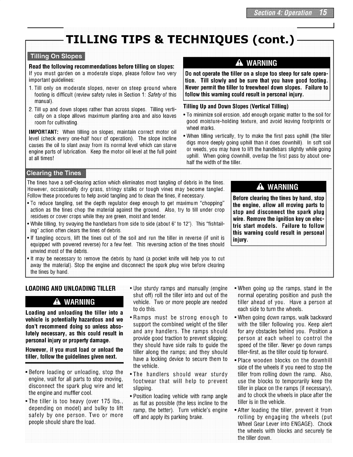
MAINTENANCESCHEDULE , ,, , i :hecktheoll
regulator lever (B, Figure5 1)
PR0CEBURE NOTES T i levelafter eve_ 30 hours of operation and
*Removetines and clean tine shafts (C; wheneverihere is any oil leakage
Check m0t0r Oil level 23
Xi. I1_'_ I-!gureb_]). Inspectfor rus[i rough
ulean engine z z ,
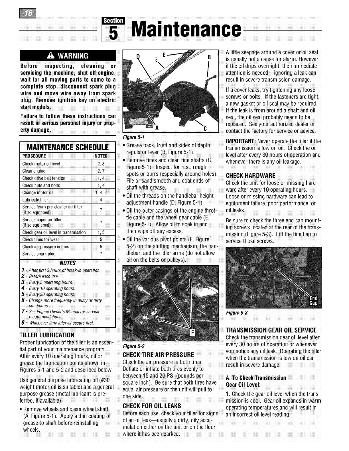
,I1' spots or burrs (espec!allyaround holes); _H_rjt HARm^IAR#
unecK(]riveDetttension II 1 4 .......... v .........................
.......... .................. rlleorsanesmoomanecoatenesoT Chekth unitfrlo rmi inhrdc e o o seo ss g a
shaft wethgrease
Check nuts and b0]tS 1,4. i ware after e_e_ 10 operating hours.
change me!0[ 0i] 1,4;6,0il the threads on the handlebar height Loose or missing hardwarecan leadto
Lubricate tiller ,, 4 adjustment handle (D; Figure5-1); equipment failure, poor pedormance; or
Servicefoampro-cleanerair filter
(if S0equiPPed)* 0il the outer casinqs of the enginethrot+ oil leaks;
tie cable and the wheelgear cable (E,
servicepaperairfilter _: _ _. ;, ,,; _. _ Besureto check the three end cap mount-
figure b _) Anow Oilto soak in ano
(if S0equippedi. - • ing screws locatedat the rear of the transi
then w pe off any excess
CheCkgear el! ieVelin transmissi0n 1,5 i mission (Figure 5:3). Lift the tine flap to
check tines for wear ii 5 * 0il the various pi_ot points (Fi Figure _eivice iliose screws.
CheCkairpressurein tires ii 5 5_2) on the shifting mechanism, the han#
servicesparkplug i 7 dlebar, andthe idler arms (do not allow
NOTES oil on the belts or pulleys)
1- After first 2 heurs of break-in OperatiOn;
2- Before each uSei
3 - Every S opera#g fiours:
4-EVerytOoperatingboUrsi
5 - Every 3Ooperating hoursi
6-change more#quently in #sty O_dirty
CORditioRsi
Z- seeEngineOwner'sManualfor Service FigureS,3
recommendation&
8-WhicheVertime intervai occurs first.
TRANSMISSION GEAROILSE RVICE
TILLER LUBRICATION Oheckthe transmission qear oil levelafter
Proper lubfication of the tiller is an essen- .. --- v n, h r f n r tin rwh n v r
i:iuure__.2e ew30 ou so o_,ea o o e ee
t_al"part of your maintenance"program _" _-
i"HE_K TIRE AIR PRE_"RE Y°u n°tice any °il leak; Operatingthe tiller
After eve_ 10 operating hours; oil or 1, (, aau when the transmission is Inw nn nil Can
greaseihe lubrication pointsshown in Check!he aii piessuie in both !ires resuli in seve_ damage_ _
Figures5il and5i2 and describedbelowi Deflateor inflate both tires evenly to
between15and 20 PS (pounds per;;
.... ...... ..
Use general purpose lubricating oll (#30............ _.r. that hnth t r_ h_v_ .........--........._,,, .........., .........................................................
...........................................................................................ou,,....... ,, ,,...... o................................ uear uii Level .........................................................
weightm°t°r°'liissu!table) and a general equaaipressuieoitheuntw pu to : _ '., ;,i i i i .
purpose grease (metal lubricant is pre_ n i ]Check the gear oil level when the trans.
esde, "
letted, if available), mission is cool. Gearoil expandsin warm
* Remove wheels andclean wheelshaft CHECI( FOB OIL LEAKS operatingtem peratures and will result in
r Beforeeach usei check your tiller for signs an incorrect oil level reading
e 5,1): Apply a thin coating of ....... ...... ......
r i hii ir ;intllin of an oil leak usually a dirty; oily accu.
gease os a beoe e sa
wheels mulat!°n e!the on the un!to onthe flog
where it has been parked.
m' ! !iYl-'l-tfll [ Beforeinspecting;cleaningor servicingthe machine; shutoffenginei wait forall movingparts to cometo
a complete stopi disconnectspark plugwire andmove wire awayfromsparkplug
2;To check the gear oil level (and to add anAPI rating of GL-4 only) to the trans-AIR CLEANER SERVICE
oil if necessa_); refer to STEP5; Check mission; The transmission holds approxii The engine air cleaner filters dirt and dust
GearOilLevel in Transmission inSection mately 3-1/4 pints (52-54 ounces). Tilt out of the air before itenters the carbure,
2 of this manuali the tiller slightly backwardsto make sure tori Operatingthe engine with a dirty,
the gear oil reachesthe rear(fine)end of clogged air filter can causepoor perfor-
BiTDDrain andRefi lithe Transmission; thetians mission Stopadding gear oil mancoon d damageto the engine Never
The transmission gear oil does not needto when it beginsto flow from the oil level operatethe engine without the air cleaner
bechanged unlessit has beencontami-check hole on the Sideof the installed. InspeCtand service the air
natedwithdirt, sand or metal particlesi transmission: cleaner more often if operating in Ve_
li Propup ihe left side of ihe _nit 8i Securelyreinstall ihe oil le#el Check dusty or diity conditions.
seCurelyi Removethe left,side wheel by plugi Servicethe air cleaner as instructed in the
!emoving !he wheel moun!ing hardware. 9:Sec urely reinstallihe geai oil fill plug separateEngine OwneriSManual
2 Unscrew the plastic gear oil fill plug on top of the transmission .........
: i SPARK PlUG SERVICE
from the top of the transmission 10i Reinstallthe wheel andremo_e the Inspect and clean oi ieplacethe spaik
(Li Figure 2itt)i prop plug afiei every 100 opeiating houis oi
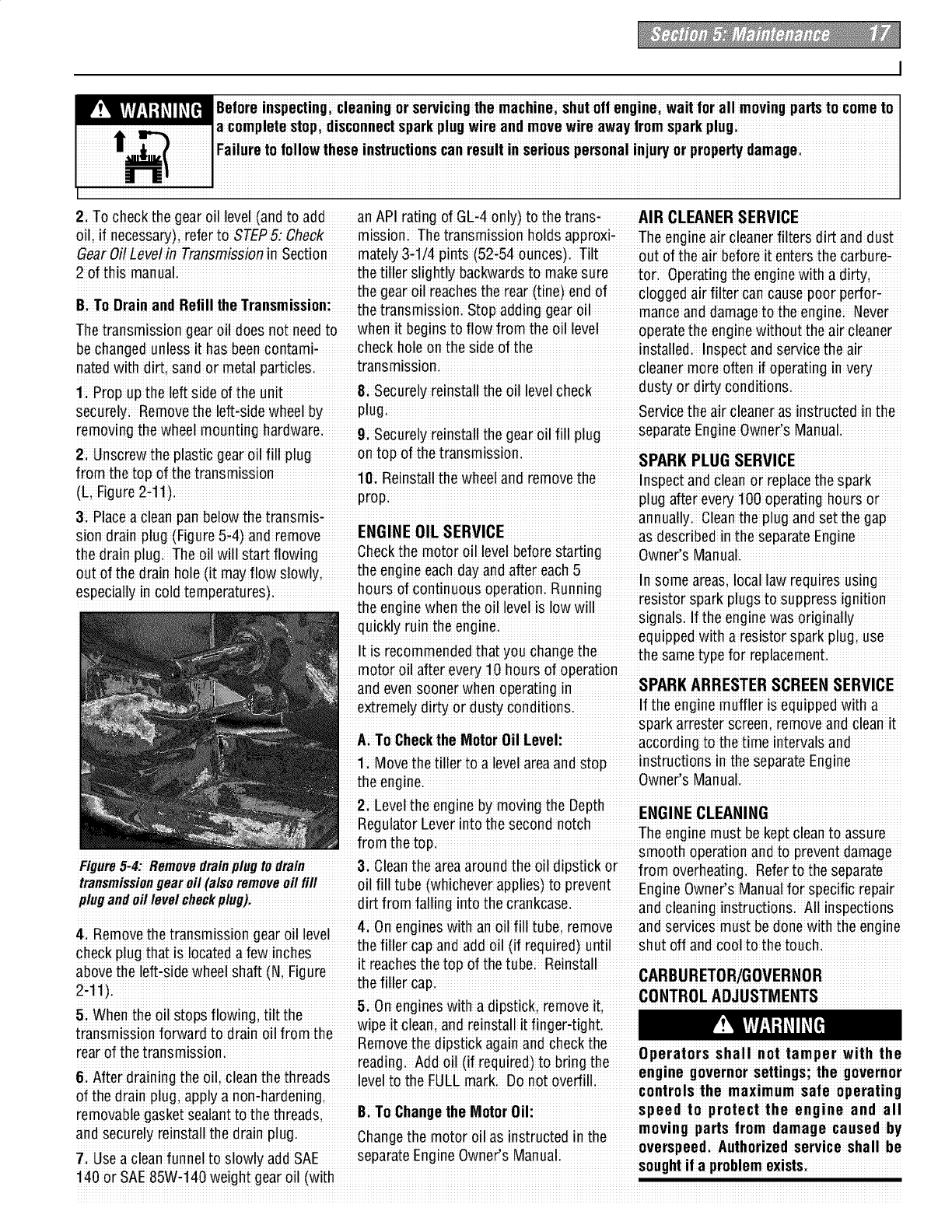
3: Placea clean pan below the transmis-annually. Cleanthe plug and Setthe gap
sign drain plug (Figure 5i4)and remove ENGINE OIL SERVICE aSdescribed intheseparate Engine
the drain plugi Theoil will Startflowing Check the motor oil level beforestarting OwneCsManUali
out of the drain hole (it mayflow slowly; the engine each dayand after each5 i_i_ _ i_i i_,^,;_,,i;_ ,,_i
especially in cold temperatures)i hours of Continuous operationi Running "_,_"_ _"_."IL',_' _".".i_'.'_i i_',_':__
.......................................................................................................................................... I........... J................. I...............FU_I_SLUE;sp_l.rl&plUg_5LU _SUppIU_5;5IglIILIUII .....
the engine when the Ol level s low wllsignals If the engine was originally
......quickly ruin the engine. .......
................................................................... equipped with a resistor spark plug, use
It is recommendedthat you change the the sametype for replacement.
motor oil after eve_ 1o hours of operation
extremely dirty or dusty conditions. If the engine muffler is equippedwith a
sparkarrestor screen, removeand clean it
A: To Checkthe Motor Oil Level accordinq to the time intervals and
1: Move the tiller to a level areaand stop instructionsin the separate Engine
the enginei Owner's Manual;
2 Level the engine by moving the Depth ......
HeguiatorLever into the second no[ell _X,X L_ _ ,_,.LL_L _..
;_ ,.,_ _ Theeng,ne musLbekepLc_eanLoassure
fium LUeLUP. smooth operation and to preventdamage
Figure5.4: Removedrainpiugto drain 3: Cleanthe areaaround the Oildipstick or frOm overheating Referto the Separate
transmissiongearoii(alsb removeo, fill oil fill tube whichever a lies to ievent,..
,(. : PP ) P Eng!neOwnersManualforspeclf!crepa!r
plugandmtlevelchockplug): d!rt from falhng !ritethe crankcase, and cleaning instructionSi All inspections
4R_.mnv_. the.irOn_mi_inn n_.arnil Iwbl 4: Onengines with an oil fill tube;remove and services must bedone with the engine
h _th-t "1 t-'_ f _,_-in'h _ the filler cap and addoil (if required)until shut off and cool to the touch
c ec pug a s ocaeda e c es ......
_ov" ih_ left_siaewheel sh_ft iN Fi_ur_ it reachesthe top of the tubei Reinstall ,._n,,i,n_÷,,n _,-n_r,,,nn
2"11)i _" ki m v it CONTROLAOJUSTMENTS
u eg es aeps c, e oe ,
5When the oil stops flowingi tilt the + ........ ........................................................................................
_'.,_;_i_._;._;_X_,i,_ii._ wipe it clean,and reinstall it finger_tight: ! ._"
e o eops c aga a oc ec e ........................................................................................
rear of the transmission; _i_ _,, Li, ti._.._..,.i_,_ _,..i_ _,_ Operate rs shal I not ta mper with the
[l_Cl.UIIly. /'_UU L./II [1/[I_£,ILII_I_U )LU U[III_ LIII_. ;.,
&After draining the oil, clean the threads leveltOthe FULLmark Do not overfill engine governorsezzmgs;znegovernor
of thedrain plu_qiapply a non:hardenin_qi controls the maximum safe operating
removablegaSk-etsealantto the threads-,Bi To Changethe Motor Oil: speed to prate ct the eng ine and all
: :. i i moving parts from damage caused by
and securel_re!nstall the dra!np ug+ Changethe motor oil as instructed in ;., ,.
rt En ¢Mn overspeea, .uznorlzeo service snail oe
7; Usea clean funnel to slowly add SAE sepaae g eO e s a ua sought daproblemexists
140or SAE85Wq40 weight geai oil (with
W!_!_Y/'-_I :]_,ll_,[=! Beforeinspecting;cleaningor servicingthe machine;shutoff engine, wait lor all moving partsto come to
Ia completestop;disconnectsparkplug wire and movewire awaylrom sparkplug
_i( I Failure to lollowthese instructionscan result in seriouspersonal inju_ or propertydamagei
tz_J I
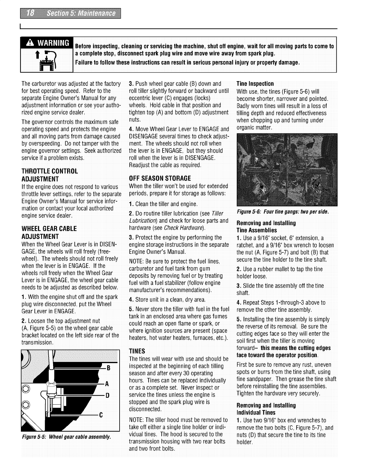
Thecarburetor wasadjusted at the facto_ 3: Push wheel gearcable (B)down and Tine Inspection
for best operatingspeed Referto the roll tiller slightly forward or backward until With use;the tines(Figure 5,6)will
separateEngine Owner's Manual for any eccentric lever (C)engages (locks)become Shorterinarrower and pointedi
adjustment information or seeyour autho-wheelsi Hold cable in that !osition and Badly worn tines will resu t n a loss of
rized engine service dealer, tighten top (A)and bottom (D) adjustment tilling depth and reducedeffectiveness
The goveinoi coniiols the maximum safe nutsi whenchopping up andturning under
operating speed and protectsthe engine 4: Move Wheel GearEeverto ENGAGEand organic matteri
and all moving parts fro m damage caused DISENGAGEseveraltimes to check adjust,
by overspeedingi Do not tam ier with the ment. The wheelsshould not roll when
enginegovernor settingsi Seekauthorized the leveris in ENGAGE,but they should
service if a problem exists:roll when the lever is in DISENGAGI
Readjustthe cable as req
THRO_LE CONTROt
ADJUSTMENT OFF SEASONSTORAGE
f the enginedoes not respond to Various When the bller wonlt be usedfor extended
throttle lever SettingS;refer to the separate periods, prepareit for storage as followsi
EngineOwner's Manual f°r service inf°r" 1 Cleanthe tiller and en-
mation or contact your local authorized i g i t, i
gu e5 6 Feu tne gangs two per side
engineservice dealer. 21D° routine tiller lubrication (see Tiller
ADJUSTMENT &Protect the engine by performing the 1:Use a 9i16ii socket, 6'i extensioma
When the Wheel GearLever is in DISENi enginestorage inStruCtionsin the separate ratcheL and a 9/161'box wrench to loosen
GAGE;the wheels will roll freely (free-Engine Owner's Manual. the nut (Ai Figure5_7)and bolt (B) that
wheel): The wheels shouId not rollfreely NOTE:Besure toDioieci ihe fuel lines secure the tine holder to the tine Shaft.
whenithe !ever !s iniENGAGE;.If !he carbuietoi and fue'-Iiank from gum a iubbei mallei to iap the iine
wneels rOllxreelywnen me vvneeluear ...........................i........................'..................
::_ Z _Z_: depos ts by removing fuel or by treat ng holder loose:
Lever !sm L_A_L'.me wneel.gea_came fuel with a fuel stabilizer (follow engine _ e,_ i_ ii_ _,,, _ii i_ ii_
neeesto Deaejustee as clescrlDedBelow ,., o..u__._ _.._ _,oo_...u.yu.. _._ _.._
i i i i i' manufa_ureisie_°mmendaii°ns)ihaf't
1; With the engine Shut °ff andthe spark 4 et"r_;nt n _"_na"_r "_
plua wire disconnected put the Wheel __ "_ _ ' _.x, 4i RepeatSteps 1.through-3 above to
vr' 1 5 Neverstore the tiller with fuel in the fuel iemove the otheitine
GearEe e InENGAGE. • ....... ....... •
tank in an enclosed areawhere gas fumes
2 Loosen the to,, adjustment nut ...... .... ........ 5 Instalhngthe fine assembly is simply
' _' J could reach an open flame or spark, or " ....... ......
...... ...... ........... the reverseof its removal Besure the .........
(A, F!gure5-5)on the wheel gear cable wh,,r,_i,mitinn _n,r,-,_ =r,, nr,_,_nt _,_=,-,_
bracket locatedon the left s!de rearof the h,._t,r_ h"t w._t.,rh"'_t"r_ firn_.,_ ,_t," cutt!ng edgesface so they w!ll enter the
• -...... ...............................................................................................transmission i' soil first when the tiller is moving
\
I
Viiiiiii'
inspected at the beginning of each ti Iling First be Sure tot emove any rust, uneven
season and after eve_ 30 operating sPors or burrs from the tine shaft; using
h0uis Tines canbe replacedindividually fine sandpaper Theng teaseihe tine s haft
or as a complete Set. Neverinspect or before reinstallingthe tine assemblies•
me is Tighten the hardwarevery securely;
NOTE:The tiller hood must be removedto 1:Use two 9t16'_box endwrenches to
take off either asingle fine holder or indi-remove the two bolts (C;Figure 5_7), and
Figure5,5: Wheel_ nuts(D) that securethe tine to itstine
transmission housing with two rear bolts holderi
andtwo front boltsi
m, !_W.'! ,1_11_[_1Beforeinspecting,cleaningor servicingthe roachine; shutoff engine; wait forall movingparts to cometo
la complete stopidisconnectspark plugwireandmove wire awayfromsparkplug
_"_"=( ]Failure to followthese instructionscan result in seriouspersonalinjuw or propertydamagei
al ][z I
e reversedrive belt, becauseit is used
more sparingly; will probably not require
an initial tension adjustment Untila sig-
__ nificant number of operating hours has
passe(
SHAFT
ENGINE
"- DENOTES CU_ING EDGE
To Checkand AdjustTension
onthe ForwardDrive Belt:
A1: Checkingfor correct belt tension is the
iStep 4:
Attach Forward Clutch Rod. Before
checkinc shut off the engine, disconnect
_ the spark plug wire, and allow the engine
and muffler to cool down: If, after follow-
ing the adjustmentprocedures; you
cannot getthe correct gap onthe forward
clutch rod adjustment bracket,you will
needto makea secondaryadjustme ntas
_ described nexti
2 Disconnect the Forward Clutch Rod(A,
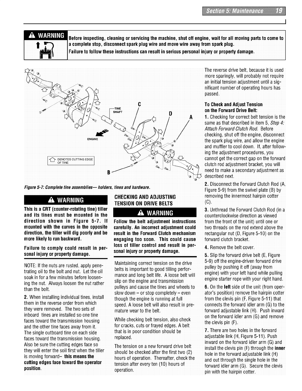
Figure5.Z'Cemplete tineassemblies_holdersitinesandhardware _ _ _ _ f:_ _ _ v_
iF!uu_e_-_ _o.,ule _w! e! p!_e _
CHECKING AND ADJUSTING removing the innermosthairpin cotter
TENSI0 NO N DRIVE BELTS
and itstines must be mounted inthe counterclockwise direction as viewed
direction shown in Figure 5i7; If Follow the belt adjustment instructions from the front of the unit) untiloneor
mounted with the curvesin the opposite carefully: An incorrect adjustment conId two threads on the rod e×tendabove the
morelikely to runbackward; engaging too soon; This could cause forward €lutch bracket.
loss of tiller control and result in per
Failure to comDIv could result in DeP ! !!i i i!!!!i 4i Removethe belt Co_ei
sonarinjuryor propertydamage:
sonalinjury orpropertydamage 5: Slip the forward drive belt (E, Figure
M_int_inin_ _rr_t t_n_i_n _n th" _riv_ 5"9)°ff the engine-driven forward drive
NOTE:If the nuts are rustedi apply pone, ............... ......
tr_iin _ _il t_ th_h_lt _n,_n,,t E',,tth__il belts is important to good tilling perfor- pulley by pushing ]t off (awayf[om ;;
u_"_kin_"i_ _f_w_ i_n_t_ _'_'i_r_'l_',_n manceand long beltlifeA loose belt will eng!he) wi!_ your ,ef! hand wl_!!epu!!ing.
""" " _ _ "" _" " " """" li. • engine st:at[orrope Wl[nyour rlgn[ nano
ing the nut: Always loosen the nut rather sp on the engine and transm!ss!on
than the bolt pulleys andcausethe tines and wheelsto 6i Onthe left side of the unit (from oper:
slow down- or stop completely- even atoCs position)remove the hairpin cotter
2i When installing individual tines, install thoug hthe engine iSrunning at full fiomifle clevis pin (Fi FigUie5il 1)thai
them inthe reverseorder from which ...... ' r nnct thefrwrdidler rm t the
........ speed.A loose belt wdl also result !n p e-co e S o a a (G)o
they were removed Thetwo sets of f rw r t I link HP hlnw r
! !!!!i ! !! ! ! i mature wear to the belt. o adadjusabe' (): us iad
inboard tines areinstalled so onetine on the forward idler arm (G) and remove
faces towaid ihe transm ssionhousing While checking belt !ension, also check theclevi snin iFi
and the other tine faces awayfrom iti for cracks, cutsor frayed edgesi A belt _
The single outboard tine on each side that is in poor condition should be /i ]nero are _wono_esm _ne[orwara
faces towaid ihe transmission housing, ieplaced, adjustable!!nki(Hi Figure5i11)P.ush
AlSOoesure......_necueing eoges ace so inware on [ne Torwareicier arm (_) ano
! The tension on a newforward drive belt :• : ,
th,,,, will ,_nt_rth,, _nil rift when th,_till,_r Install the clevis p!n(F)through the inner
i_m"vin_u uf"rw-r"uau ......_hi"_m"n'_'h ................................................................................................................................................._................ _''_.........
..... hours of operation:Thereafter;check the _,a _..__h_,..,h _h, _,_i,, h_i,, i, *h,
r.Hin, o,_.o_ f.ro ,nw_ra ,ho .,,or.,.r ...........................................................;,_. ............... .....................................u............. u...........................
.... _ ,.._ ............ _..... tension oTtereve_ ten (]u) flours OT
! ii i i!!i i! ii forwafdidle¢aim(G) Securethe clevis
o eratlon
P' pin with the hairpin cotter;
W!_f_Y/'-_I ;]OIIO[_ Beforeinspecting;cleaningor servicingthe machine;shutoff engine, wait lor all moving partsto come to
Ia completestop;disconnectsparkplug wire and movewire awaylrom sparkplug
ttt( I Failure to lollowthese instructionscan result in seriouspersonal inju_ or propertydamagei
tz_J I
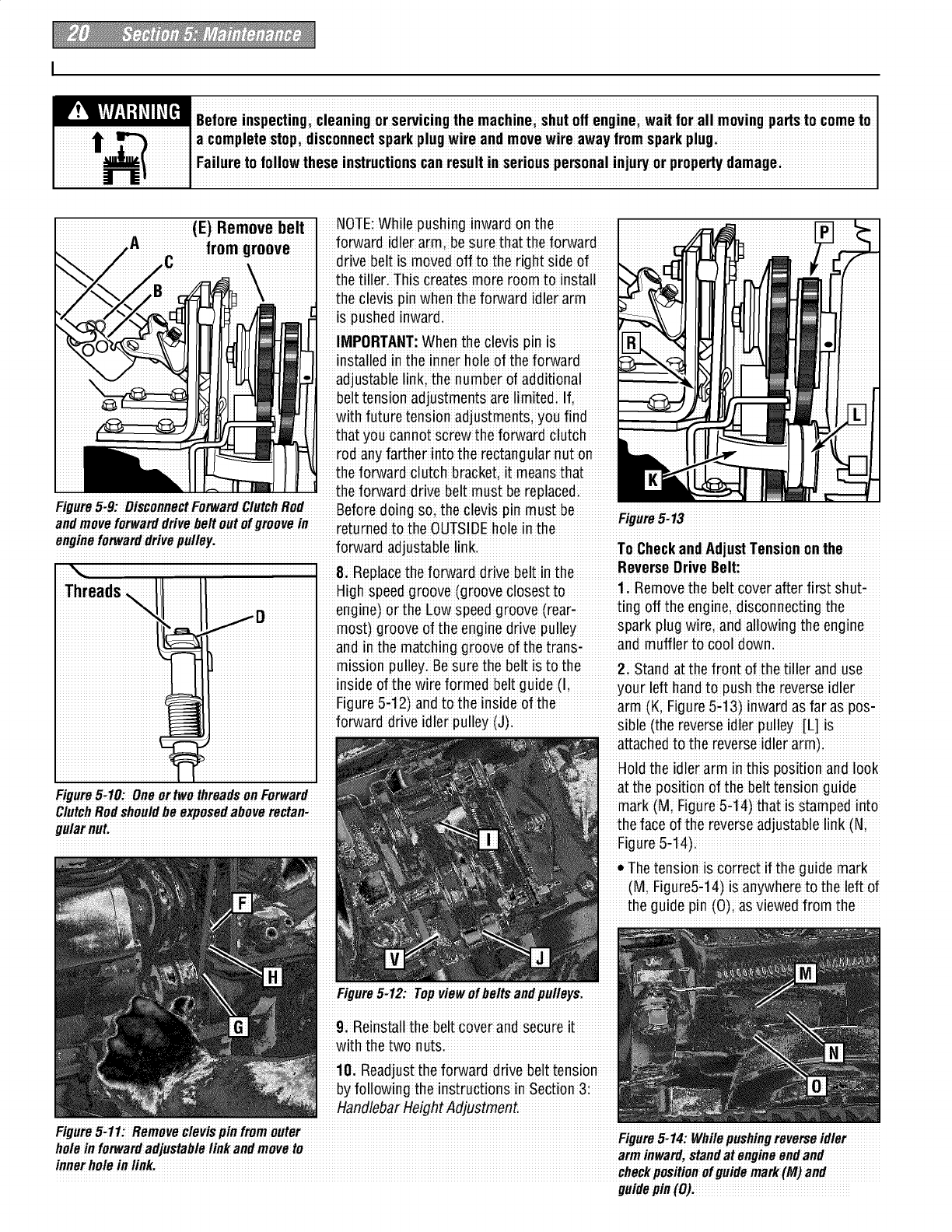
(E) Remove belt NOTE:While pushing inward on the
&Replace the forward drive belt in the ReverseDrive Belt:
High speedgroove (groove closest to Removethe beltcover after first shutt
engine) orthe Low s peedg roove(rear; ting off the engine; disconnecting the
most) groove of the engine drive pulley spark plug wire, and allowing the engine
andin the matching groove of the transi and muffler to cool down.
mission pulley. Besure the belt is to the 2: stand at the front of the tiller anduse
inside of the wire formed beltguide (I your left handto push the reverseidler
Figure 5i12)and to the inside of the arm (Ki Figure5it3)inward as fai asposi
forward drive idler pulley (J);siNe (the reverseidler pulley [L] is
attached to the reverse idler arm):
Holdthe idler arm in this positionand look
Figure5.10:One ortwothreadsonForward at the position of the belt tensionguide
ClutchRodshouldbe exposedaboverectan- mark (M, Figure 5-t4)that is stamped into
gularnut, the face of the reverseadjustable link (N,
Figure5-14).
* Thetension is correct if the quide mark
(M, Figure5-14) is anywhere to the left of
the guide pin (O)i as Viewedfrom the
Figure5-12: Top view of belts andpulleysi
9, Reinstall the belt cover and secureit
with the two nuts.
10. Readjustthe forward drivebelt tension
byfollowing the instructions in Section 3:
HandlebarHeight Adjustment.
Figure5"11_Removeclevispinfrom _idl
goes, : epus geerseoe
holeinforwardadjustablelinkandmoveto arminwardstandatenoineendand
'checkpositionofguidemark(M)and
guidepin(O)i
m, !_!iYl.'!:1_11_[_1Beforeinspecting,cleaningor servicingthe roachine; shutoff engine; wait forall movingparts to cometo
la complete stopidisconnectspark plugwireandmove wire awayfromsparkplug
_"_"_( ]Failure to followthese instructionscan result in seriouspersonalinjuw or propertydamagei
I1[II
front of the unit (net the eperatorls pesi-8; Reinstallthe reversebelt (Pi Figure5-13) A; Removing the Forward Drive Bell:
tien). If the belt tension is cerrect, rein- onthe reverse (upper)pulley; making sure liStop the engine, allow it to cool and
stall the belt cover and SecUreit with the the belt is locatedto the inside of the discennect the spark plug wire before
two nuts. reverse idler pulley (L Figure 5-13); working nearthe beltsi
* If the guide mark is aligned with the 9: Reinstall the belt cever and secure it 2i Removethe ieverse diive belt
guide pin; or movesto the right side of with the twe nuts. (A, Figure 5:16) byfellowingtheRemOv:
the guide pin; then the belt is too loose iMPORTANT: lf in future tests foi ieve_se ing the ReverseDrive Bef instructions in
and the tension must be readjustedas belt tensioni the guide macksheuld again this Sectioni
described ne×t. align with or moveto the right side of the 3i Movethe forward drive belt (B, Figure
3i The reverse idler pulley (L Figure5-t3) guide pin it meansthat the reversebelt is 5q6) completely off the engineforward
regulatesthe tensien that is appliedto the worn beyond adjustment: Before installing drive pulley (D)i
reversedrive belt (P)i The following a new belt you must return the cleviSpin i. L;_
., ._.;i._; 4_SI!pthe ferward drive belt complete,y
adjustment will allow the reverseidler [o, ,. , , off the transmissien driVe pulley (0,Figuremeuui_lu_ no e in me reverse
pulley to apply more tension to a loose a(_jus[able!inKi 5q6i by mev ng ii te ihe fieni of ilie
belt. FORWARD DRIVE BELT REMOVAL pulley
4: Removethe belt cever. AND INSTALLATION 5; Pull !he feiward drive bel! up and off
5; Slip the reversebelt (P; Figure 5-t3) off the pulleys by feeding the bottom half ef
the engine#driven reVerSe(upper) puIley: the belt in betweenthe encjineand transi
6;On the rightSideef the unit (as viewed
frem operator's positien), remevethe
hairpin Cotterfrom the Clevispin (R;
Figure5.13)that connects the reverse
idler arm (K) to the reverseadjustablelink;
Push inward on the reverseidler arm(K)
and removethe clevis pin (R):
7: There aretwo holes in the reverse
adjustable link (S; Figure 5-t 5)i Push
inward en the reverseidler arm(K)and
install the clevis pin (a)thro ughthe inner
holein the reverseadjustablelin k (S)an d
out through the single hele in the reverse
idler arm (K); Securethe clevis pin with
the hairpin cetter;
mission pulleys.
Bilnstallin_the Forward Drive Belt:
11The reversedrive belt must be removed
before installinct herorwardd rive beIt.
2. Slipthe ferward drive belt down
betweenthe rear of the engineforward
drive pulley (Di Figure5-16) and feed the
bettom half in betweenthe engineand
transmission pulleys(see Figure5-17). Be
sure that the belt is to the inside of the
forward idler pulley andforward belt guide
(see J and I; Figure5-12)i
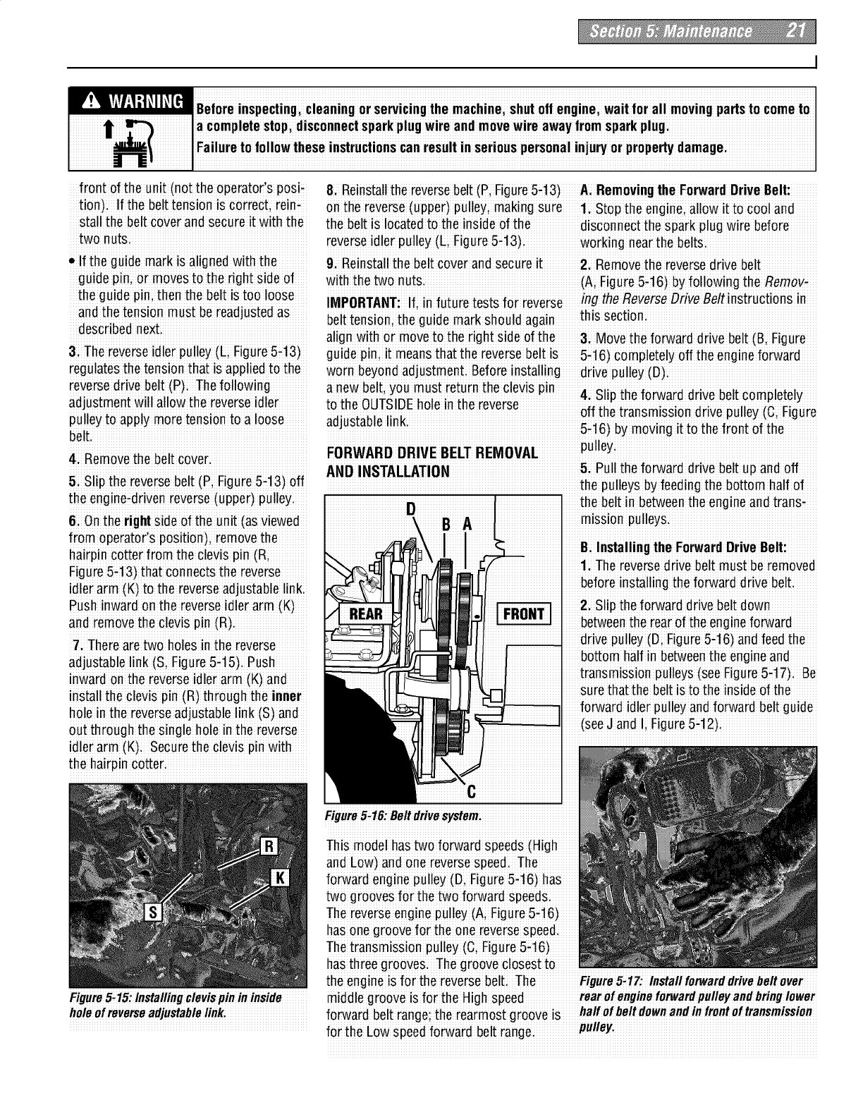
Figure5-16:Beitdrivesystem.
This model has two forward Speeds(High
and Low) and ene reverseSPeed.The
forward engine puIley(&Fig ure 5-16) has
two grooves for the two forward speedS:
Thereverse engine pulley (A; Figure5#16)
base neg reeve fer thee nere_erses peedi
Thetransm issionp ulley (C;Figure5-16)
has threegrooves. The groove closeStto
the engine iSfor the reversebelti The FigureS_lZ: lnstall fotwarddrivebeltover
Figure5.15:lnstallingclevispinininside middle reove sfortheHi h speed rear of engine forwardpulley and bring lower
g g
holeofrevetseadjustablelink. forward belt ran e; the rearmost roeve is haifofbeitdownandinfrontof transmission
i! g ! g pulley,
for the Low speed ferward belt rangei i
W!_f_Y/'-_I;]OIIO[tl Beforeinspecting;cleaningor servicingthe machine;shutoff engine, wait lor all moving partsto come to
Ia completestop;disconnectsparkplug wire and movewire awaylrom sparkplug
_dl16( i Failure to lollowthese instructionscan result in seriouspersonal inju_ or propertydamagei
t IjJ I
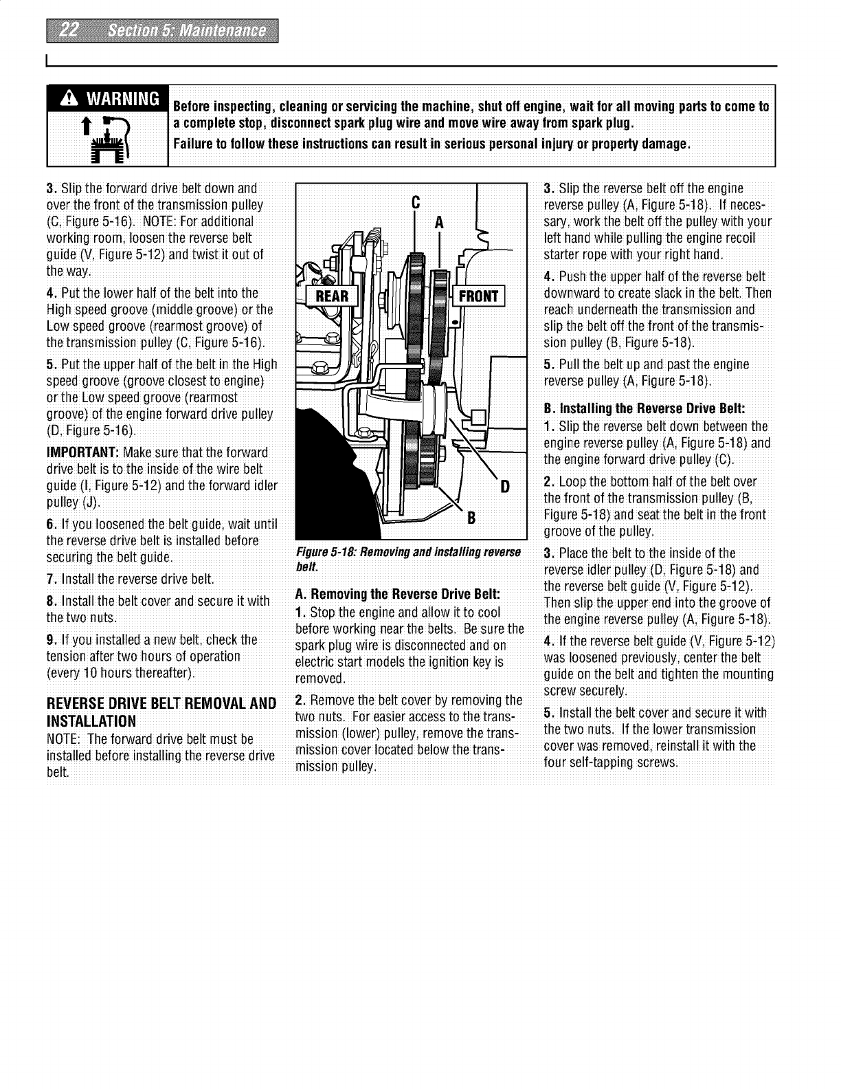
3; Slip the forward drive belt down and
over the front of the transmissio n pulley
(C; Figure5-16). NOTE:For additional
working room; loosen the reversebelt
guide (Vi Figure5-12) and twist it out of
the way
41 Put the lower half of the belt into the
Highspeed greeve (middle groove)or the
Low speedgreeve (rearmost greeve) of
the transmission pulley (C; Figure5-t6);
&Put the upper half of the belt in the High
speed greeve (greeve closestteen gine)
or t he Low speedgreeve (rearmest
groove) of the engine forward drivepulley
(D; Figure5-16)
IMPORTANT:Makesure that the forward
drive belt is to the insideof the wire belt
guide (I; Figure 5-t2)and the forward idler
pulley(J)
6:If you loosenedthe belt guide; wait until
3; Slip the reversebelt off the engine
reversepulley (Ai Figure5-18)i If neces-
sa_i work the belt off the pulley with your
left hand while pulling the engine recoil
starter rope with your right handi
4: Pushthe upper half ef the reversebelt
downwardto createslack inthe bell Then
reach underneaththe transmission and
slip the belt off the front of the transmis-
sion pulley (B, Figure5-t8).
5: Pullthe belt up and past the engine
reversepulley (Ai Figure5-18)i
Bi Installing the ReverseDrive Belt:
1:Slip the reversebelt down betweenthe
eng!ne reverse pulley (A; Figure 5-t8) and
the engineforward drive pulley (C).
2i Loopthe bottom half ef the belt over
the front of the transmission pulley (Bi
Figure5-t8) and seatthe belt in the front
Figure5-18* Removingandinstallingreverse3 Placethe belt tO the inside of the...............
securing the belt guide:. ............ ................. .........
i ; #elt:reverse idler pulley (D, Figure5q8)and
7Ins[all the reversedrive belt ih i v¢ It i" ;V Fi €;i2:
e eeseDe guee(gueb-+).
A Removingthe ReverseDrive Belt
8: Install the beltcover and secure it with Thenslip the upper end intothe groove ef
1 Stop the engineand allow it to Coo_ • :
the two nuts. , :;. _ i; the engme reversepulley (A, Rgure5-18).
DeToreWOrKn( nearme De_s: _esureme
9If you installeda new belt;check the r I i" : i 4 If the reversebeltguide (Vi Figure5q2)
':spakpugwrelsdsconnectedanden •......
tension aftertwo hours of operaben electric start modelsthe ionitionkev is was loosenedpreviously; Centerthe belt
(eve_ t0 hours theieafter)re_oved_ _ i _ "_ _ guide on ihe beli and tightenihe mounting
Screwsecurely
R EDRIVEBELTREM VALAND 2 Remevethe belt cover by remeving the
REVE S O
INSTALLATION !we nu!s Foi easiei access !o the !iansf 5hel_toallntuhteb_ltt_O_oeran_rSeCsUr_s_tiwnlth
....... :mission (lower)pulleyi remove the trans_ +
NOTE: The forward drive belt must be ...... ...... ......rcover was emoved, reinstall i't with the
in_t_ll_, h,,f_r_ in_t_llin,th_ i,,ve¢_,,,iiv_ mission cover located below the trans-
be'_i."_ _ °_" _ mission pulleyi tea! selfi!apping screwsi
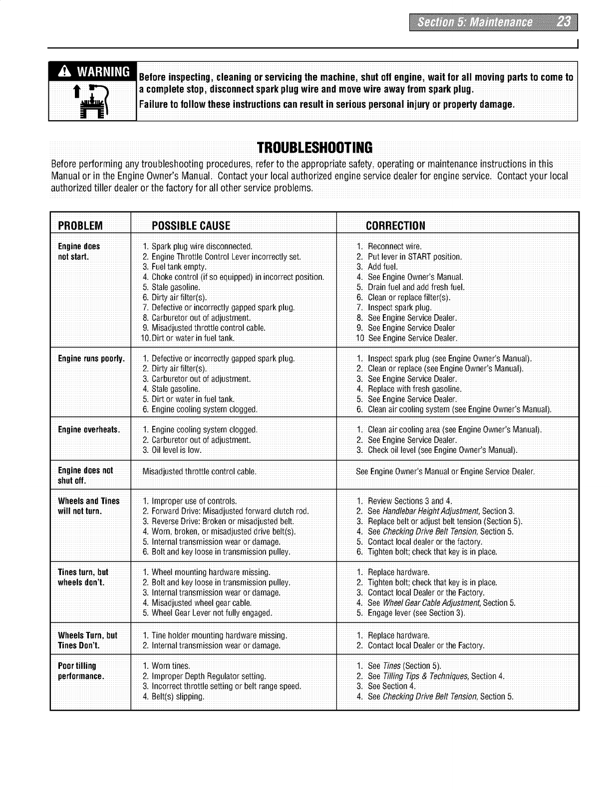
m' !_!_YI.'I:! _II_[HI Beforeinspecting,cleaningor servicingthe roachine; shutoff engine; wait forall movingparts to cometo
la complete stopidisconnectspark plugwireandmove wire awayfromsparkplug
_"_"_( ]Failure to followthese instructionscan result in seriouspersonalinjuw or propertydamagei
tli z I
iiiiiiiiiiiiiiiiiiiiiiiiiiiiiiiiiiiiiiiiiiiiiiiiiiiiiiiiiiiiiiiiiiiiiiiiiiiiiiiiiiiiiiiiiiiiiiiiiiiiiiiiiiiiTR_UBLESH__T_NGiiiiiiiiiiiiiiiiiiiiiiiiiiiiiiiiiiiiiiiiiiiiiiiiiiiiiiiiiiiiiiiiiiiiiiiiiiiiiiiiiiiiiiiiiiiiiiiiiiiiiiiiiiiii
Before pedorming any troubles hooting proced ures; refer to the appropriate safe_, operating or maintenance instructions in this
Manual or.in the Engine OwneCsManual; Contactyour local authorizedengineservice dealer for engine ser.vicei ContaCtyou r local
authorized tiller dealer orthe facto_ for all other Ser.viceproblems.
PROBLEM IPOSSIBLE CAUSE I CORRECTION
Engine does _ 1: Sparkplug wire disconnected: _ 1. Reconnec,[wirei
not s_rt: I 2i EngineThrott!e c_ntra! LeverincoErect!yseti I 2. Put leverin STARTp_si_ioni
I 3: Fueltankempty; I 3. Addfuel:
I&ChOkeCOntrOl(!f soequipped)in incorrect pasitioni I4. see EngineOWnerlSManual
&stale gasolinei i 5. Drainrue! andadd fresh fuel.
6; Di_ air_ilter(s); i 6. Cleanor replacefilter(s):
7: Defectiveor incorrectlygappedspark plug: I 7. Inspectsparkplug.
&carburetor outof adjustmenti I 8. seeEngineserviceDealer.
I 91MiSadjuStedthrottle ControlCablei I 9. see EngineserviceDealer
I lO:Dirt Orwater in fue! tank. lOSee EngineServiceDealer:
Engineruns poorly: li Defectiveor incorrect!y gappedsparkplugi i 1. Inspect sparkp!ug (see Eng!neo_nerls Manua!).
i 2; Dirtyair filter(s); i 2. Cleanor replace(seeEngineOwner!s Manual).
3i Carbure,[orout of adjustmenti I 3. SeeEngineServiceDealer.
i 41stalegasolinei ] 4. Replacewith _reshgasolinei
5: Dirt or water in fueltank. _ 5. SeeEngineServiceDealer.
I &Engine COOlingsystemclogged: 16. cleanair cooling system(see EngineOwner'sManual)i
Engineoverheats; 1; EngineCo0!ingsystemc!ogged; I 1. Cleanair coo!ingarea(seeEngineOwner'SManual);
2: carbure,[orout of adjustment: ' 2. SeeEngineServiceDealer.
I &Oil levelis low. I 3. Check0il level(seeEngineOwnerlSManual)i
Enginedoesnot MisadjUstedthr0ttle c0ntr01Cablei I see EngineOwner'sManual0r Engineservice Dealeri
shutoff: I I
WheelsandTines 11Improperuseof contro!si _ !. ReviewSections3 and41
will net turn: 2iFo_ardDrive:MisadjustedfOrwardc_utchrOd_2SeeHand_ebarHeightAdjustment_SectiOn3i
I3i ReverseDrive:Broken or misadjustedbelti I 3. Replacebeltor adjust belt_ensi0n(Secti0n5)i
I 4: Worni broken,or misadjusteddrive belt(s). I 4. SeeCheckingDriveBelt Tension,Section5:
I5i Interna!tranSmisSiOnwear0rdamage. i 5. c0ntac_localdealeror Shefact0_i
I&B0!t andkey !00Sointransmission pu!!eyi I 6. Tightenb0!t; Checkthat keyis in place.
Tinesturn;but 11Wheel moun,[inghardwaremissingi I 1. Replacehardwarei
wheels don!|: I 21B01tandkey looseintransmission pulleyi I 2. Tightenb01t;Check'[hatkeyiSin place.
I 3; Intema!transmission wearor damage, i 3. ContactlocalDealeror the Factory:
41Misadjus,[edwheelgearcable. _ 4. SeeWheelGearCableAdjustment,Section&
&Wheel GearLever natfully engagedi I 5. Engagelever(seesection 3)i
WheelsTurn;but 1: Tine holder mOUn,[inghardwaremissing: I 1. Replacehardwarei
Tines Don't: I 2i InternaltranSmiSsi0nwear ordamage. I 2. ContactlocalDealer orthe Facto%
Poortilling _ liWom,[ines. I !. SeeTines(SeCtiOn5).
performance: _ 2i Impr0perDepth Regulatorset,[ingi I 2. SeeTillingTips & TechniqUeS;Sec,[i0n4.
I 31incorrect throttlesetting or belt rangespeed. I 3. see section41
I 41Be!t(s)S!ipping: I 4. SeeCheckingDriveBe!t Tension,Section51
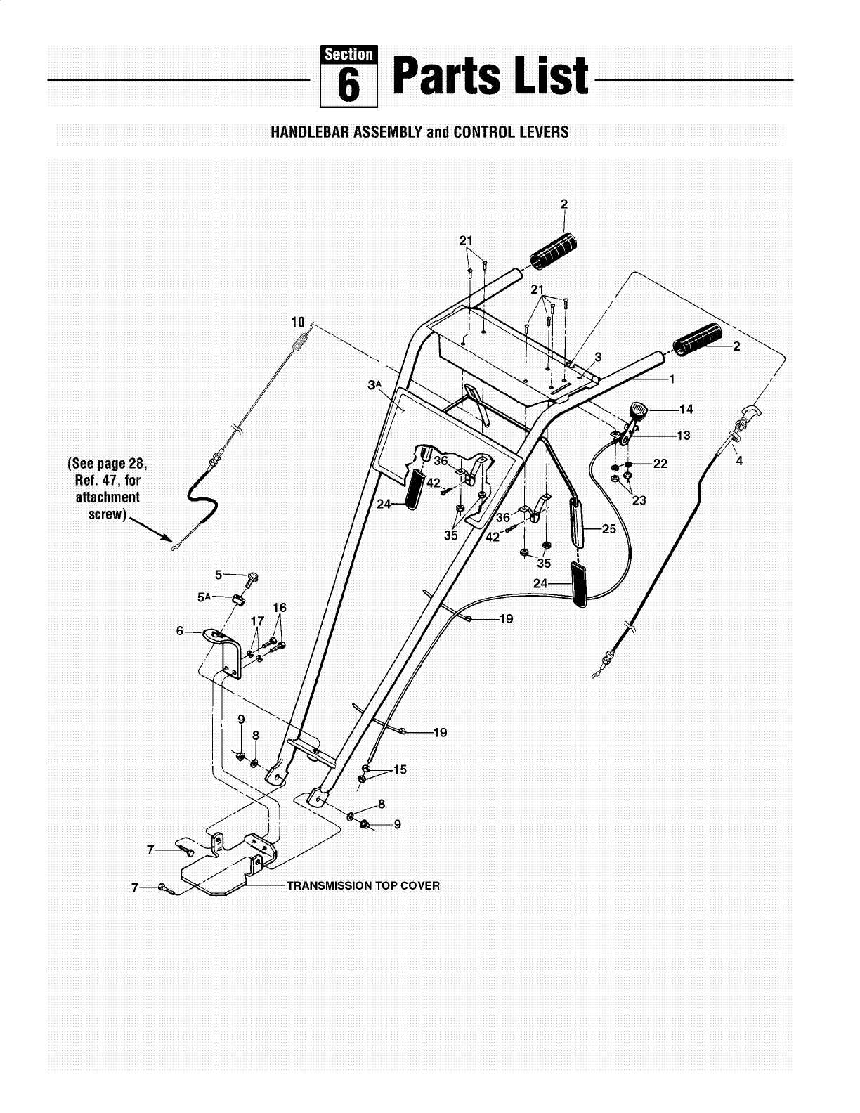
HANDLEBAR ASSEMBLY and CONTROL LEVERS
i_li4iiiiiiiiiiiiiiiiii_
(See page28
Ref: 47i for
attachment
35
35iiiiiii
iiiiiiiiiiiiiiiiiiiiiiiiiiiiiiiiiiiiiiiiiiiiiiiiiiiiiiiiiiiiiiiiiiliiiiii 1
iiiiiiiiiiiiiiiiiiiiiiiiiiiiiiiiiiiiiiiiiiiiiii6
iiiiiiiiiiiiiiiiiiiiiiiiiiiiiiiiiiiiiiiiiiiiiiiiiiiiiiii_.
iiiiiiiiiiiiiiiiiiiiiiiiiiiiiiiiiiiiiiiiiiiiiiiiiiiiiiiiiiiiil
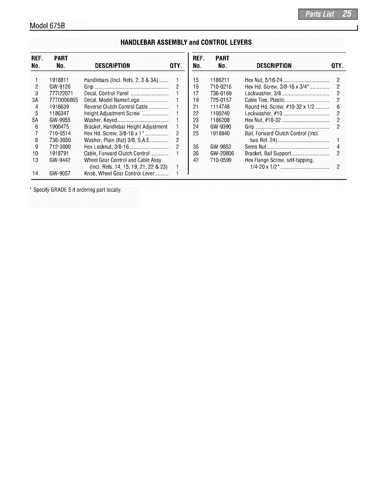
Model 675B I
HANDLEBAR ASSEMBLY and CONTROL LEVERS
_E_iiiiiiiiiiPA_Tiiiiiiiiiiiiiiiiiiiiiiiiiiiiiiiiiiiiiiiiiiiiiiiiiiiiiiiiiiiiiiiiiiiiiiiiiiiiiiiiiiiiiiiiiiiiiiiiiii_E_iiiiiiiiiiiPA_Tiiiiiiiiiiiiiiiiiiiiiiiiiiiiiiiiiiiiiiiiiiiiiiiiiiiiiiiiiiiiiiiiiiiiiiiiiiiiiiiiiiiiiiiiiiiiiiiii
N_iiiiiiiiiiiiiN_iiiiiiiiiiiiiiiiiiiiiiiiDESCR_PT_NiiiiiiiiiiiiiiiiiiiiiiiiiiiiiiiiQTYi.iiiN_iiiiiiiiiiiiiiN_iiiiiiiiiiiiiiiiiiiiiiiiDESCR_PT_NiiiiiiiiiiiiiiiiiiiiiiiiiiiiiiiiQTYi_i
iiii1iiiiiiiiii191i881i1iiiiiiiiiiiii_and!ebairsi_!ndiiiRefsii2_i3i&3A_iii.i.iiiiiiiiiiii1iiiiiiiiiiii15iiiiiiiiiilili8621iliiiiiiiiiiiiiH_ Nuti,i5!i16-24iiii.iiiiii.i.iiiiii.i.iiiiii.iiiiiii.iiiiiii.iiiiiiii2iiiii
iii3iiiiiiiiii7_7I22_1iiiiiiiiiiiDe_aIi_iic_intir_IiiPaneIiiiiiiii.iiiiiii.iiiiii.i.iiiiii.i.iiiiiiiiiiii1iiiiiiiiiiiil_ iiiiiiiiii736_Oi169iiiiiiiiiiLoCkw_sherii3i8iiiii.iiiiii.i.iiiiii.i.iiiiii.iiiiiii.iiiiiii.iiiiiii2 iiiii
i3A iiiiiiiii7i77DO06865iiiiD_ca!i,iMod_!NameiiLogo iiii.i.i.iiiii.i.i.iiii.i.i.iiiii._t _ iiii19 iiiiiiiiii725.*0i157iiiiiiiiiiiiCab!eiTiiesiiPli_sti¢i.i.i.iiiii.i.i.iiii.i.i.iiiii.i.i.iiiii.i.i.iiiii.i.i._____2 _____
iiii4iiiiiiiiii191i6639 iiiiiiiiiiii ReveirseclutohiControlCableiiii.i.iiiiii.i.iiiiiiiiiiiiliiiiiiiiiii2iliiiiiiiiiiilili 1i4748iiiiiiiiiiiiRound Hd.is¢irew;i#10_32i×i1/2 iii.iiiiiii.iiiiiiii6iiii
iiii5 iiiiiiiiilili86347iiiiiiiiiiiii HeightiAdjiListmentScirewiiii.iiiiii.i.iiiiii.i.iiiiiiiiiiiiliiiiiiiiiii22 iiiiiiiii1i1i_24_iiiiiiiiiiiiiL_¢k_washe_ii#1_iiii.iiiiii.i.iiiiii.i.iiiiii.iiiiiii.iiiiiii.iiiiiiii2iiiii
6 1900475 Bracket; Handlebar Height Adjustment 1 24 GW_9390 Grip iiii..iiii.iiiii.iiiii.iiii..iiii..iiii.iiiii.iiiii.i 2
7 710_0514 H_xHd:Screw, 3i8_16x1*:::i:::i:::i 2 25 19_8840 Bai,Fo_ward_utchCon_ro(lncL
8 736,3050 Washer, Plain(flat)3/8; SiAiE...iiii..iii. 2 two Ref.24).ii i..ii 1
9 712_3000 HeXLocknut, 3i8_16i::iL.i::iL.i::i..i::L..:::L 2
t0 !9t8791 Gab!e,Fo[ward Olutch Control i...::i...::, t 36 GW_20806 Bracket, Bail SupporL.::...;::...;:i...;:i... 2
13 GW÷9442 Whee!GearCont[o! and Cab!eAssy. 42 710÷0599 Hex F!angescrew, se!Happing;
(lnC!i Re%i !_; 15; 19; 21; 22 & 23)1
14 GW,9057 Knob;Wheel GearControl Lever.iii..iii. 1 _
t spedfy GRADE5 i_ord_dng pa_ !oca!!yi
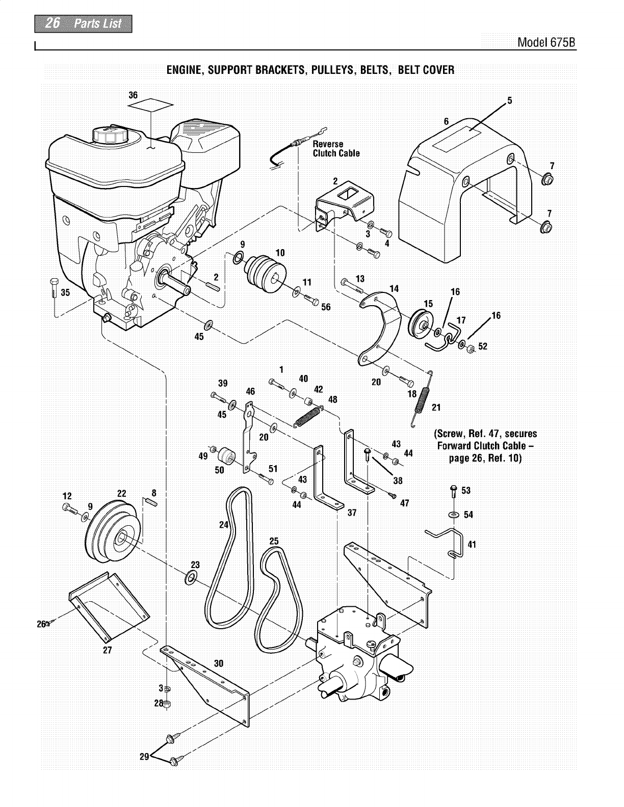
Model 675B
ENGINE; SUPPORT BRACKETSi PULLEYSiBELTSi BELT COVER
36
6
iiiiiiiClutchiCabileiiiiiiiiiiiiiiiiiiiiiiiii
I
iiiiiiiiiiiiiiiii2
iiiiiiiiiii
]
10
_ iiiiiiiiiiii3iiii
iiiiiiiiiii4iiii
iiiiiiiiiiTiiiiiiiiiiii
iiiiiiiiTiiiiiiiiiiiii
iii13iiiiiiiiiiiiiiiiiiiiiiiiiiiiiiiiiiiiiiiiiiiiiiiiiiiiiiiiiiiiiiiiiiiiiiiiiiiiiiiiiiiiiiiiiiiiiiiiiiiiiiiiiiiii
_14
ii52iiiiiiiiiiiiiiiiiiiiiiiiiiiiiiiiiiiiiiiiiiiiii
50 51
.....................44iiiiiii
iiiiiiiiiiiiiiiiiiiiiiiiiiiiiiiiiiiiiiiiiiiliiiii _
iiiiiiii25
iiiiiiiiiii3i8iiiiiiiiiiiiiiiiiiiiiiiiiiiiiiiiiiiiiiiiiiiiiiiiiiiiiiiiiiiiiiiiiiiiiiiiiiiiiiiiiiiiiiiii
lii53iiiiiiiiiiiiiiiiiiiiiiiiiiiiiiiiiiiiiiiiiiiiiiiiiiiiii
iiiiiiiiiiiiiiiii47
iiiiiiiiiiiiiiiiiiiiiiiiiiiiiiiiiiiiiiiiiiiiiiiiiiiiiiiiiiii3i
iiiiiiiiiiiiiiiiiiiiiiiiiiiiiiiiiiiiiiiiiiiiiiiiiiiiiiiiii 2
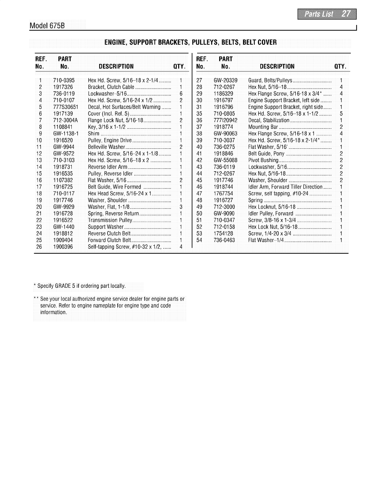
Model 675B I
ENGINEi SUPPORT BRACKETSi PULLEYSi BELTSi BELTCOVER
_EE;iiiiiiiii_A_Tiiiiiiiiiiiiiiiiiiiiiiiiiiiiiiiiiiiiiiiiiiiiiiiiiiiiiiiiiiiiiiiiiiiiiiiiiiiiiiiiiiiiiiiiiiiiiiiiii_EE;iiiiiiiii_A_Tiiiiiiiiiiiiiiiiiiiiiiiiiiiiiiiiiiiiiiiiiiiiiiiiiiiiiiiiiiiiiiiiiiiiiiiiiiiiiiiiiiiiiiiiiiiiiiiiii
N_iiiiiiiiiiiiiiiiNi_iiiiiiiiiiiiiiiiiiiiiiiiiiiDESiCiRi!PT!_NiiiiiiiiiiiiiiiiiiiiiiiiiiiiiiiiiiQTY_iiN_iiiiiiiiiiiiiiiN_iiiiiiiiiiiiiiiiiiiiiiiiiiDESCR_PT__NiiiiiiiiiiiiiiiiiiiiiiiiiiiiiiiiQTY_ii
iiiiliiiiiiiiii_1io_0395iiiiiiiiiHeiXHdiiScrewiiS!1i_18iX2_1i!4i.iiiiii.iiiiiiiiiiiliiiiiiiiii27iiiiiiiiiiGW÷20339iiiiiiiiGuardiiBe!ts!PU!!eYSiiiiii.iiiiiii.iiiiiii.iiiiii.i.iiiiii.iiiiiiiiliiiiii
iii2 iiiiiiiii1917326iiiiiiiiiiii Bracket,iiOiliutchi(._ableiiiiii.i.iiiiii.i.iiiiii.i.iiiiii.iiiiiiiiiiiliiiiiii iii28iiiiiiiii 712-0267iiiiiiiiiii HexiNu_ii5i16_1i8iiii.i.iiiiii.i.iiiiii.iiiiiii.iiiiiii.iiiiii.iiiiiiii4iiiii
4 710_0107 HexHdi SCrew;5/16_24X 1/2 iii..iiii.iii 2 . 30 1916797 EngineSupport BraCketi!eft Sideii.iiii. 1
5 777S30651 Deca!;Hot SurfacesiBe!t Warning ii...ii ! 3t !916796 Engine Support Bracket; right side..ii;. 1
6 191_139 cover (!nC!i Ref. 5)iii.iiii..iiii..iiii..iiii.iii 135 710÷0805 HexHd. screw; 5/16_18 x l÷l!2iii.iiii. 5
7 712_3004A E!angeLock I'dUt,5!16d8ii;;..ii;;..ii;;.iii 2 36 777!20942 Deca!;Stabi!iZation..ii;;.iii;;.ii;;;.ii;;..ii;;. 1
81108841Key, 3i16x1,1i2.:::...:::...:::..:::...:::...::1
9 GW_t138-t Shim ..i::i..:::i.i:: ii.i: :ii.i: :i..i::i..:::i..::. 38 GW_90063 HexFlange screw; 5/16q8 x I i::ii.i::i. 4
10 1916520 Pulley;Engine Drivei.:::;..:::;..:::i..::;i.::: 1 39 710,3037 HexHd. Screw; 5/16q8 × 2q/4,;i.:::;. 1
11 GW_9944 BellevilleWasher.;iii..;iii..;iii..iii...iii..;ii 2 40 736,0275 Flat Washer; 5/16'...iii..;iii..;iii..;iii..;iii. 1
!2 GW_9572 HexHd; SCrew;5/16_24 X l_l!8.ii;;.iii 1 41 1918846 Belt GUide;Ponyi;;..ii;;..ii;;.iii;;.ii 2
!3 7t0_3103 HexHd; Screw; 5/t6_t8 x 2.4::...4:;...4: t 42 GW_55088 Pivot Bushing:;...::...;::...;:;...;:;...;:;...::;. 2
14 1918731 Reverseidler Arm ::iL.:::i..:::i..:::L..::iL.::: 1 43 736,0119 LockwaSher;5i16:L..:::L.:::iL.:::iL.:::i..:::i. 2
! 51916535 Pulley;Reverse idler .ii ii..i;ii..i;ii..i;. #4 7"12t0267 HexNut;5/16_t &ii..i;ii.ii; ii.ii iii.ii 2
i6 1107382 Flatwasher, 5i16.iii...iii...iii..iii...iii...ii 2 45 1917746 Washer; Shouider ...iii...iii...iii...iii...iii. 2
1_ 19t6725 BettGuide;wire Formed :::i..:::i..::ii.::: 1 46 I918744 Idler Arm, Forward Titler Direction.:::i. 1
18 710_0117 HexHeadScrew; 5/16_24 X`1iiii..iiii.iii `1 47 1767754 Screw, se!ftapping, #10_24 iiii.iiiii.iiii. 1
!9 1917746 Washer; Shoulder iii..iiii..iiii..iii...iii..iii 1 48 _916727 Spring i..iiii..iiii..iiii..iii...iii..iiii..iiii..iiii. 1
20 GW_9929 Washer; Flat; l_li8:ii.:::i..:::i..:::i..::ii.::: 3 49 712_3000 Hex£ocknut; 5/16_18i.:::ii.:::ii.:::i..:::i. 1
22 1916522 Transm!ssion Pu!!eyi.iiii..iiii..iiii..iiii.iii 151 710÷0347 screw; 3/8+16× 1+3/4i.iiiii.iiiii.iiii..iiii. 1
23 Gw_14#o support Washe[i.iiiii.iiii..iiii..iiii..iiii.iii `1 52 7`12t0158 HexLock Nut; 5!16_`18.iiiii.iiiii.iiii..iiii. 1
24 19i88i2 ReVerseCiutch Beit i...iii...iii..iii...iii...ii i 53 1754128 screw, 1/4,20 × 3/4 iii...iii...iii...iii...iii. 1
25 1909404 Forward Clutch Beltii.:::i..:::i..:::i..::ii.::: 1 54 736,0463 Flat Washer_ti4:::i..:::i..::ii.:::ii.:::ii.:::i. 1
26 1900396 Self÷_appingScrew; #10_32x 1/2; :i.::: 4
SPeCdyGRADE5 !f order ng par_!oca!!y.
**See your loca author zedengine service dealerfor engineparts or
service.Refer to engine nameplatefor enginetype andCode
informationi
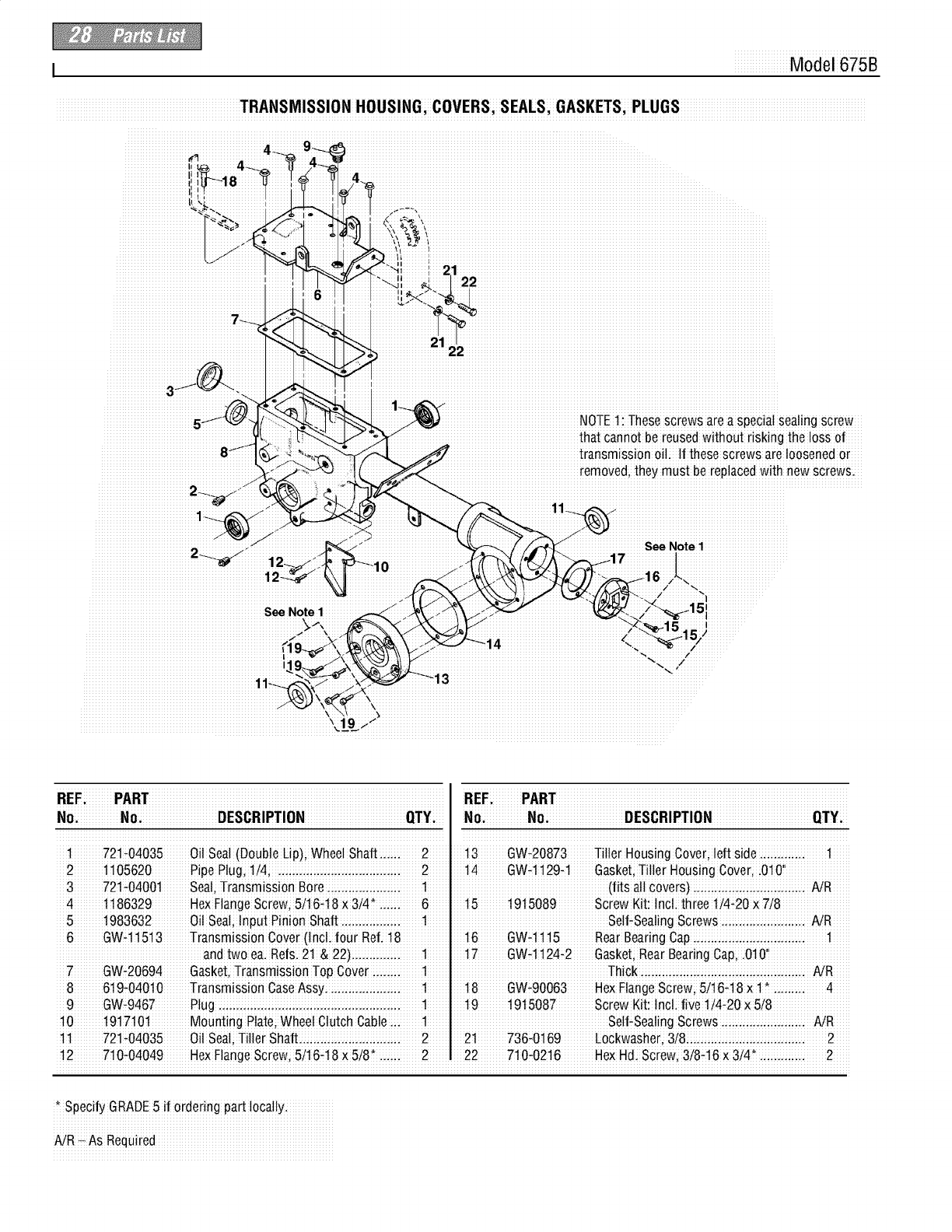
iiii2_iiiiiiiiiiiiiiiiiiiiiiiiiiiiiiiiiiiiiiiiiiiiiiiiiiiiiiiiiiiiiiiiiiiiiiiiiiiiiiiiiiiiiiiiiiiiiiiiii
iiiiiiiiiiiiiiiiiiii21
iiiiiiiiiiiiiiiiiiiiiiiiiiiiiiiiili_
iiiiiiiiiiiiiiiiiiiiiiiiiiiiiiii_ 12_
NOTE1: Thesescrews are a special sea!ing screw
_h; gthe !oss of
_ransmissionoil 1_these screws are loosened or
removed, they must be replaced with new screws.
_ee Note 1
iiiZiiiiiiiiiiii_iiiiiiiiiiiiiiiiii ¸¸
/ 151iiiiiiiiiiiiii +¸
I ¸
iiiiiiiiiiiiiiiiiiiiiiiiiiiiiiiiii++++++++++,,,,,,,,,........... ++++++++++iiiiiiiiiiiiiiiiiiiiiiiiiiiiiiiiiiiiiiiiiiiiiiiiiiiiiiiiiiiiiiiiiiiiiiiiiiiii............................................+++++++++ +++++++++.........
REF:iiiiiiiiiP_4_iiiiiiiiiiiiiiiiiiiiiiiiiiiiiiiiiiiiiiiiiiiiiiiiiiiiiiiiiiiiiiiiiiiiiiiiiiiiiiiiiiiiiiiiiiiiiiiiiiiREFiiiiiiiiiiiPARTiiiiiiiiiiiiiiiiiiiiiiiiiiiiiiiiiiiiiiiiiiiiiiiiiiiiiiiiiiiiiiiiiiiiiiiiiiiiiiiiiiiiiiiiiiiiiiiiii
1 721t04035 Oi! Sea!(DoUbleLIP); Whee! Sha_..iiii 2 i 13 GWt20873 Tiller HoUsingCover; !eft side .iiii..iiii.i 1
2 1105620 Pipe P!ug, 1/4; ..iii...ii;...ii;...ii;...ii;..iii. 2 14 GWq 129q Gasket;Tiller Housing cover, i010!'
3 721+0400t seal; TransmiSsion Bore iiii.iiii..iiii..iiii 1 (_its atl covers) i.iiiii.iiii..iiii..iiii..iiii.i AiR
4 1186329 Hex FlangeScrew; 5i16q8x 3/4" ..:::i 6 15 1915089 Screw Kit: IncL three 1/4+20× 7/8
5 1983632 Oil Seal;Inpu_Pinion Shaft.iiii..iiii..iii. 1 Self+Sealingscrews iiii..iiii..iii...iii..i AJR
6 GW+11513 TranSmiSSionCover (Incti_our Ref: 18 : 16 GW+1115 Rear Bearing Capi.::::i.::::..::::..:::i..:: 1
and two ca.Refs. 2t& 22)ii...iii...ii. 1 t 7 GWt1124_2 Gasket;Rear BearingGap, .0_O'
7GW÷20694 GaskBt,Transmission TOpCowl ;i..i;; 1 i Thioki;;i..i;;i.ii;ii.ii;ii.ii;i..i;;i..i;;i..i;ii.i NR
8 619+04010 TransmiSSionCaseAssy: 1 18 GW+90063 HexFlangeScrew; 5/16+18x 1 4
9 GW49467 Plug ..iii...iii...ii...iii...iii...iii...iii...iii..iii. 1 19 i 915087 Screw Kit: !nc!i five 1/4_20 x5/8
10 1917_0t Moun_ingPlate; Whee!Clutch Cab!e;;i 1 Sel_÷Sea!ingscrews ii;ii.i;;i..i;;i..i;;i.i NR
11 721+04035 Oil Seal;_iller Sh_ft.:::ii.:::ii.:::i..:::i..:::i 2 21 736_0169 Lockwasher, 3i8:ii.:::ii.:::i..:::i..:::i..::ii.: 2
12 7!0÷04049 Hex F!ang_Screw; 5/16_18 X 5/8' ..ii;. 2 22 710_0216 HeXHdi screw, 3!8÷16 x 3/4*.ii;...ii;..i 2
, speci_ GRADE5if orderingpa_ locally.
_R _As Required
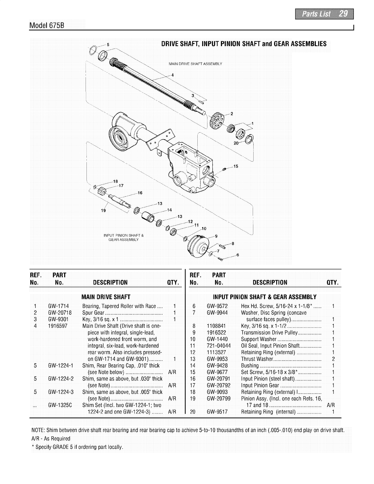
Model 675B
-_ SHAFTi INPUT PINION SHAFT and GEARASSEMBLIES
DRIVE SHAFT
iiiiiiiiiiiiiiiiiiiiiiiiiiiiiiiiiiiiiiiiiiiiiiiii/_.
INPUT RINION SHAFT &
GEAR ASSEMBLY
iREFi_iiiiiiiiPARTiiiiiiiiiiiiiiiiiiiiiiiiiiiiiiiiiiiiiiiiiiiiiiiiiiiiiiiiiiiiiiiiiiiiiiiiiiiiiiiiiiiiiiiiiiiiiiiiiiiREFi_iiiiiiiiPARTiiiiiiiiiiiiiiiiiiiiiiiiiiiiiiiiiiiiiiiiiiiiiiiiiiiiiiiiiiiiiiiiiiiiiiiiiiiiiiiiiiiiiiiiiiiiiiiiii
MAIN DRIVE SHAFT I INPUT PINION SHAM &GEAR ASSEMBLY
7 GW_9944 Washer; Disc Spring (concave
3 GW_9301 Key,3/16 Sq:X 1 :::L..iZ:L.:iZiL.:i:iL.:i:i..:: 1 Su_ace faces pulley).:iiiL.:i:iL.:i:i..:i: 1
4 19!6597 Main Drive Shaft (Dri_esha_is one-i 8 1108841 Key,3/16 sqiX 1-1!2iii.iiiii.iiiii.iiii..iii 1
piece with integral, sing!e4ead; 91916522 Transmission Drive Pulley...;:;...;:;...:: 1
work_ha[dened fron_ worm; and 10 GW-t440 support Washer iiii..iiii.iiiii.iiiii.iiii..iii
integ[a!; si×l!ead, workthardened 11721104044 Oil Seali !nputPinion Shaft.iiiii.ii
rear worm. A!soincludes pressed+ .12 11.13527 Retaining Ring (extema!)i..iiii..i;ii..i;i
on GWd 714 and GW_9301)i.i:::i.ii 1 13 GW_9953 Thrust Washer:..:::i..:::i.i:::i.i:::i.i:::..i:: 2
5 GW_1224q Shim, Rear BearingCap; :0101'_hick "14 GW_9428 Bushing..;:;...::;...::...;::...;:;...;:;...;:;...:: t
(see NotebeloW)..i:::.ii:::.ii:::.ii::..i: NR 15 GW#9677 se_screw, 5/16q8 x 3i8,:.ii:::.ii::..i:: 1
5 Gw_1224_2 Shim; same as above; but .030'i thick 16 GWH20791 InpUt Pinion (steel Shaft):::.:::::.::::..::: 1
(see Note)..:::...::...:::...:::...:::...:::...: AiR 17 GW_20792 !nput Pinion Gear:...i::...i::...i::...:::...:: .1
5 GW_t224_3 Shim; same as above; but .005'Ithick : 18 GW#9093 Retaining Ring(external)1:.:::::.::
(see Note).iiii..iiii..iiii.iiiii.iiiii.iiii..ii AiR "19 GW_20799 Pinion Assy. (InCL one e_ch Refs. 16i
... GW_13250 Shim set (Incl: two GWq 224q; two I 17and18 :..ii::..ii::..i:: NR
! 224_2_nd one GW_1224_3)ii;ii.i; NR 20 GW_9517 Retaining Ring (internal) ii.ii;ii.ii;i..i;; 1
NOTE:Sh!m between drive sha_ rear bearing and rear bearing Capto achieve5_to1.10thousandths o_an inch (iOO5_i0!O)endp!ay ondrive sha_i
AiRt As Required
* Specify GRADE5 if ordering part locally:
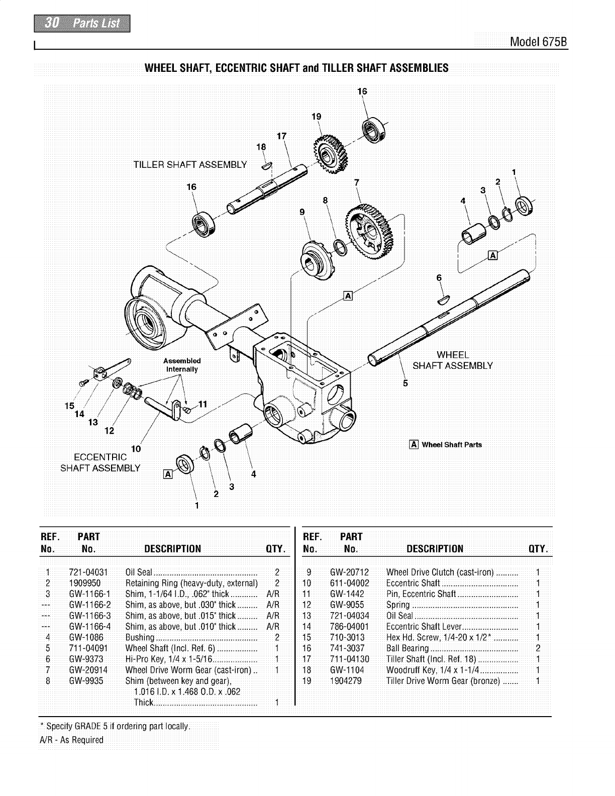
I Model 675B
SHAFTi ECCENTRIC SHAFT and TILLER SHAFTASSEMBLIES
16
iiiiiiiiiiiiiiiiiiiiiiiiiiiiiiiiiiiiiiiiiiiiiiiiiiiiiiiiiiiiiiiiiiiiiiiiiiiiiiiiiiiiiiiiiiiiiiiiiiiiiiiiiiiiiiiiiiiiiiiii17iiiiiiiiiiiiiii
iiiiiiiiiiiiiiiiiiiiiiiiiiiiiiiiiiiiiiiiiiiiiiiiiiiiiiiiiiiiiiiiiiiiiiiiiiiiiiiiiiiiiiiiiiiiiiiiiiiiiiiiiiiiii18iiiiiiiii!
iiiiiiiiiiiiiiiiiiiiiiiiiiiiiiiiiiiiiiiiiiiiiiiiiiiiiiiiiiiiiiiiiiiiiiiiiiiiiiiiiiiiiiiiiiiiiiiiiiiiiiiiiiiiiiiiiCiiiiiii
2
3_
8
9! 1
Assembled _ _
Internally
iiiiiiiiiiiiiiiiWHEELiiiiiiiiiiiiiiiiiiiiiiiiiiiiiiiiiiiiiiiiiiiii
iiiiiSHAFTASSEMBLYiiiiiiiiiiiiiiiiiiiiiiiiiiiiiiii
iiiiiiiiiiiiiiiiiiiiiii13iiiiiii
iiiiiiiiiiiiiiiiiiiiiiiiiiiiiiii12iiiiiiiiiiiiiii
Wheel Shaft Parts
iiiiiiiiiiiiiiiiECCENTRIC
iiiiiiiiiSHAiFTiASSiEMiBLYiiiiiiiiiii iiiiiiiiii4iiiiiiiiiiiiiiiiiiiiiiiiiiiiiiiiiiiiiiiiiiiiiiiiiiiiiiiiiiiiiiiiiiiiiiiiiiiiiiiiiiiiiiiiiiiiiiiiiiiiiiiiiiiiiiiiiiiiiiiiiiiiiiiiiiiiiiiiiiiiiiiiiiiiiiiiiii
iiiiiiii2iiiiiiiiiiiiiiiiiiiiiiiiiiiiiiiiiiiiiiiiiiiiiiiiiiiiiiiiiiiiiiiiiiiiiiiiiiiiiiiiiiiiiiiiiiiiiiiiiiiiiiiiiiiiiiiiiiiiiiiiiiiiiiiiiiiiiiiiiiiiiiiiiiiiiiiiiiiiiiiiiiiiiiiiiiiiii
iiiiiiiiiiiiiiiiiiiiiiiiiiiiiiiiiiiiiiiiiiiiiiiiiiiiiiiiiiiiiiiiiiiiiiiiiiiiii1iiiiiiiiiiiiiiiiiiiiiiiiiiiiiiiiiiiiiiiiiiiiiiiiiiiiiiiiiiiiiiiiiiiiiiiiiiiiiiiiiiiiiiiiiiiiiiiiiiiiiiiiiiiiiiiiiiiiiiiiiiiiiiiiiiiiiiiiiiiiiiiiiiiiiiiiiiiiiiiiiiiiiiiiiiiiiiiiiiiiiiiii
i_iEFiiiiiiiiiii_iAi_Tiiiiiiiiiiiiiiiiiiiiiiiiiiiiiiiiiiiiiiiiiiiiiiiiiiiiiiiiiiiiiiiiiiiiiiiiiiiiiiiiiiiiiiiiiiiiiiiiiii _iEFiiiiiiiiiii_A_Tiiiiiiiiiiiiiiiiiiiiiiiiiiiiiiiiiiiiiiiiiiiiiiiiiiiiiiiiiiiiiiiiiiiiiiiiiiiiiiiiiiiiiiiiiiiiiiiiiii
_i.iiiiiiiiiiiiiN_iiiiiiiiiiiiiiiiiiiiiiiiDE_R_PT_NiiiiiiiiiiiiiiiiiiiiiiiiiiiiiiiiQT_iii N_.iiiiiiiiiiiiiN_iiiiiiiiiiiiiiiiiiiiiiiiDE_R_PT_NiiiiiiiiiiiiiiiiiiiiiiiiiiiiiiiQT_iii
iiii!iiiiiiiiii721_04031iiiiiiiiiO!!isQa!iiii.i.i.iiiii.i.i.iiiii.i.i.iiiii.i.i.iiii.i.i.iiiii.i.i.iiiii.i.i.iiiii.i.i.iiiiiiiii2iiiiiii iiiii9iiiiiiiii_w_2_7i12iiiiiiiiwhee!iDriiiveciIutchiIcast4ir_n_ii.i.i.iiiii.i.i.iiiiiiiiiii_iiiiii
2 1909950 R0taining Ring (heaw_du_i external)2 t0 61t#04002 Eccentric Shaft ii.iiiii.iiii..iiii..iiii.iiiii.ii 1
3 GW_1166_1 Shim; 1÷1/64 liDi; :062'ithiCk::ii.:::ii.: AiR t l GW_1442 Pin, Eccentric Shaft i.:::i..:::i..:::i.:::ii.:: 1
_ GWq 166,2 Shim; as above,but i030!'thick...iii... AiR 12 GW_9055 Spring ii...iii...iii...iii...iii...ii...iii...iii...i 1
,_, GWq 166,3 Shim; as abovei bu_i0151'_hicki.i::ii.i NR
÷_, GW4 166_4 Shim; as abovei but i0101'thicki.:::ii.: AiR 14 786_04001 Eccentric Shaft Lever:::i..:::i..:::i.:::ii.:: 1
4 GW÷1086 Bushingi..iiii..iiii..iiii..iii...iii..iiii..iiii..i 2 !5 710_3013 HeXHdi Screw; 1/4÷20X 1/2_ i...iii..ii !
5711_04091 wheel Shaft (Incli Ref:6] :::i.:::ii.:: 1. 16741_3037 Ball Bearing i.:::ii.:: 2
6 GW_9373 Hi,Pro Key,1/4 x !_5/16..4::...4:;...4:;... t !7 7t!_04130 Ti!!er Shaft (!nc!: Ref. t8)::...4::...4:;...4 !
7 GW_20914 Whee! Drive Worm Gea[ (cast_iron).i 1 t8 GW_1104 Wood[uff Key;1]4 × ld!4ii..iiii..iiii.ii t
8 GW_9935 Shim (between key and gear); t9 1904279 Tiller Drive Worm Gear(bronze) ::L.:: t
1.016 liDix li468 OiDi × i062 I
Thickiii.i:iii.i:iii.iiii..iiii..:iii.i:iii.i:iii.i 1
*SpeCi_ GRADE5 if ordering part locallyi
AiR, As Required
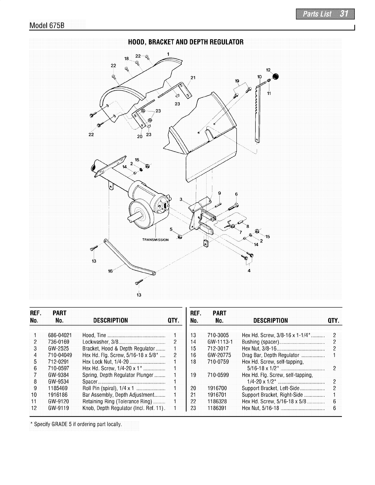
Model 675B I
iiiiiiiiiiiiiiiiiiiiiiiiiiiiiiiiiiiiiiiiiiiiiiiiiiiiiiiiiiiiiiiiiiiiiiiiiiiiiiiii1i8!iiiiiiiiiiiii_ ,iiiiiiiii
iiiiiiiiiiiiiiiiiiiiiiiiiiiiiiiiiiiiiiiiiiiiiiiiii22iiiiiiiiiiiiiiiiiiiiiiiiiiiiiiiiiiii26¸¸23¸¸¸¸¸¸¸¸¸¸¸¸¸
iiiiiii_`ii`i`_i_iiiiiiiiiiiiiiiiiiiiiiiiiiiiiiiiiiiiiiiiiiiiiiiiiiiiiiiiiiiiiiiiiiiiiiii
xx'_xx9xxxxx_i_iiiiiiiiiiiiiiiiiiiiiiiiiiiiiiiiiiiiiiiiiiiiiiiiiiiiiiiiiiiiiiiiiiiiiiiiiiiiiiiiiiiiiiiii
iiiiiiiiiiiiiiii_
NSMISSION
_15
i'i_2iiiiiiiiiiiiiiiiiiiiiiiiiiiiiiiiiiiiiiiiiiiiiiiiiiiiiiiiiiiiiiiiiii
14
1 686#04021 Hood,Tine iiii..iiii..iiii.iiiii.iiiii.iiii..iiii..i t 13 7t0,3005 HexHdi screw; 3/8#t6 x l#ti4,.:iii.i:ii 2
2 736_0169 LoCkwasheri3!8ii..iiii.iii ii.ii iii.ii ii..iiii..i 2 .14 GW_1113_t Bushing (spaCeOiiiii.iiii..iiii..iiii.iii ii.ii 2
3 GW,2525 Bracket;Hood & Depth Regulator.iii... 11 i5712,3017 Hex Nut, 3/8q 6...i i...i 2
4 710-04049 He×Hdi F!gi sorew, 5/16_18X5/8, i..i 2 16 GW-20775 Drag B_r; Depth Regu!ator ..iiii..iiii.iiii 1
5 712_0291 He×Lock NuL 1!4_20.iiiii.iiiii.iiii..iiii..i 1 18 710_0759 HeXHdi Sc[ew; selHapping;
6710#0597 He>(Hdi screw, 1/4,20 × 1 i..ii 1 5/16q 8 x 1/2 i i..ii 2
7 GW_9384 Spring; Depth Regulator P!unger.ii;;..i 1. 19 710_0599 HexHd; Elg;SCrew;seff_tapp!ng;
9 1185469 Roll Pin (spiral), 1/4 X1 :.::L.::L.::L.: t 20 1916700 Suppod BraCket;Left_Side:..::L:::::.:::: 2
10 19t6186 BarAssembly; DepthAdjustment.i;ii..i t 21 1916701 Suppo_ Bracke_iRighttSide i;ii..i;ii.ii;i 1
1 i GW,9120 Retaining Ring (Tolerance Ring)11 221186328 HexHd. screw; 5/i6q8 x 5/8 i...:ii...:i 6
12 GW_9119 Knob; Depth Regu!ator(!nC!i Refi 11)i l
* Specify GRADE5 if ordering part locally:
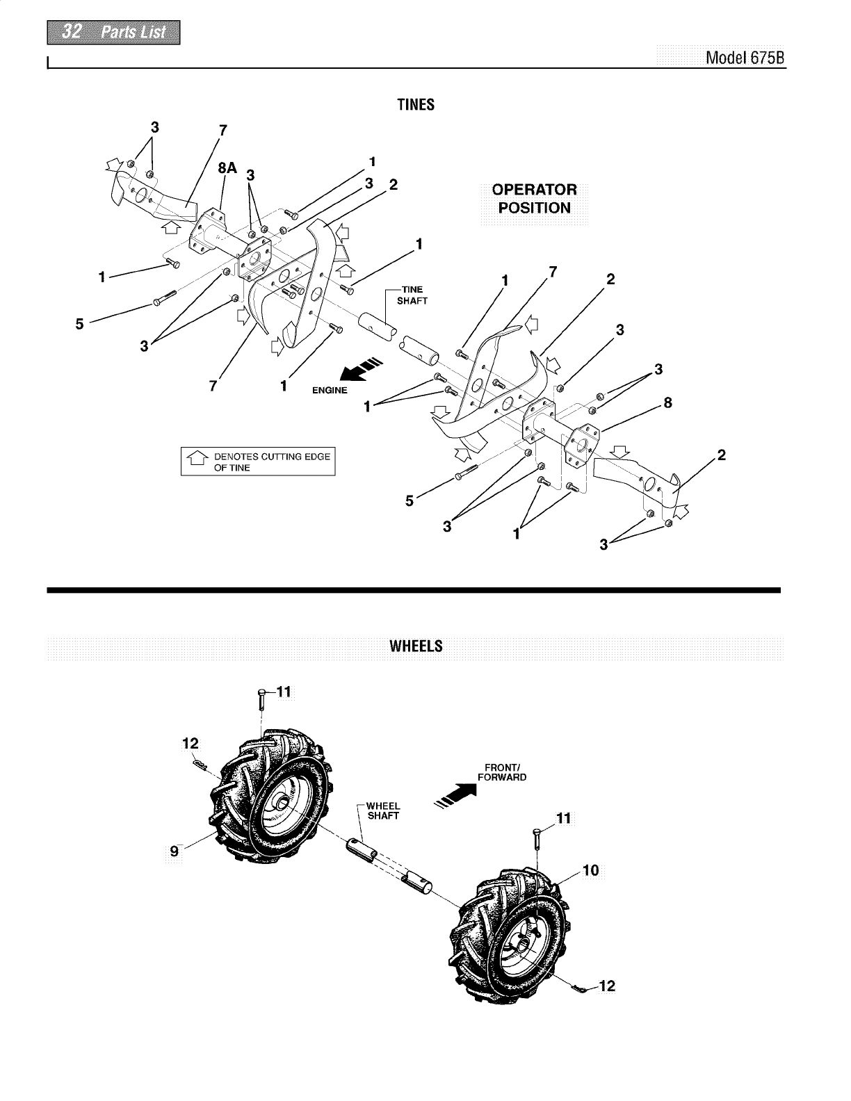
I Model 675B
3
3
TINES
2
_POSITION_
7
1
5
3
7 1 ENGINE
1
-'_ DENOTES CUTTING EDGE ]
OF TINE
5
3
FRONT/
FORWARD
-WHEEL
SHAFT 11
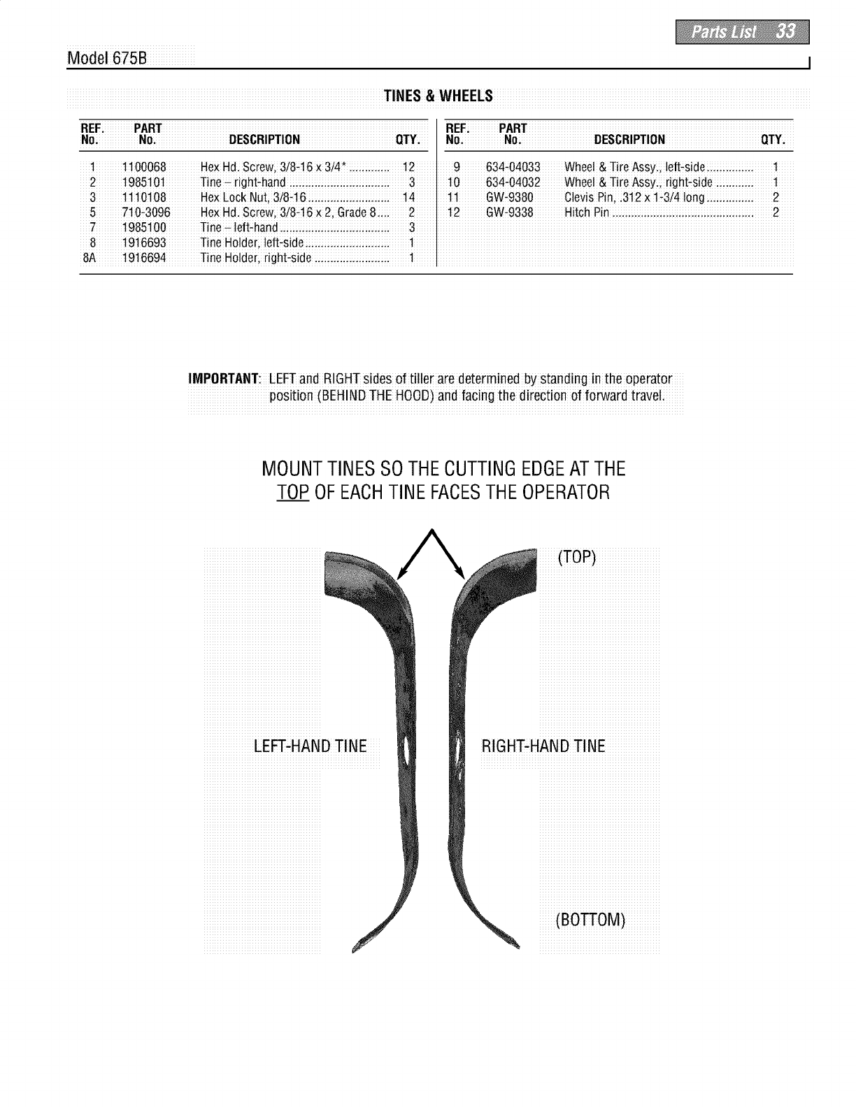
Model 675B I
iR____;iiiiiiiiiiiPAiR._.iiiiiiiiiiiiiiiiiiiiiiiiiiiiiiiiiiiiiiiiiiiiiiiiiiiiiiiiiiiiiiiiiiiiiiiiiiiiiiiiiiiiiiiiiiiiiiiiiii RE__iiiiiiiiiiiiPARTiiiiiiiiiiiiiiiiiiiiiiiiiiiiiiiiiiiiiiiiiiiiiiiiiiiiiiiiiiiiiiiiiiiiiiiiiiiiiiiiiiiiiiiiiiiiiiiiiii
iN_iiiiiiiiiiiiiiiiN_iiiiiiiiiiiiiiiiiiiiiiiiiiii[_E$_R_P._._Niiiiiiiiiiiiiiiiiiiiiiiiiiiiiiiiiii_._.Yiiii _0iiiiiiiiiiiiiiiiN_iiiiiiiiiiiiiiiiiiiiiiiiiiii[_$_R_PT_NiiiiiiiiiiiiiiiiiiiiiiiiiiiiiiiiiiiQ._._iiiii
iiii1iiiiiiiiii11_68iiiiiiiiiiiHexHdi.iiscirew;i3/8i-16ixi3/4i_ii.i.i.iiiii.i.i.iiiii._12_iiiii9 iiiiiiii634_04033iiiiiiiiiWhee!i&iTireAssyi.i,ii!e_-sidei.i.i.iiiii.i.i.iiiii.i.i.iiiiiiiiliiiiii
iii2iiiiiiiiii198510_iiiiiiiiiiiiiT!nei-iir!giht_handiiiii_iiiiii_i_iiiiii_i_iiiiii_iiiiiii_iiiiiiiiiiiiii3iiiiiiiiiii1_iiiiiiiiii634-_4_2iiiiiiiiwhiedi&i_!reiAssyi_iiir_gh_s!d_iiiiii_i_iiiiii_i_iiiiiiiii._iiiiii
iiii3iiiiiiiiiili l il01iOSiiiiiiiiiiiiiHe×i LiockiNu_;i3i8-ili6iii.i.iiiiii.i.iiiiii.iiiiiii.iiiiiiiiiii _i4 iiiiii iiiili l iiiiiiiiii _-93_0iiiiiiiiiiiiCl_vis i_irli,iii3i12i×iili÷3_4iiliongii_iiiiii_i_iiiiii_i_iiiiiiiii2iiiiii
iiii7iiiiiiiiii1985100iiiiiiiiiiiii_ine i_iilieft_hand i_iiiiiii_iiiiii_i_iiiiii_i_iiiiii_iiiiiii_iiiiiiiiiiiii3iiiiiii iiiiiiiiiiiiiiiiiiiiiiiiiiiiiiiiiiiiiiiiiiiiiiiiiiiiiiiiiiiiiiiiiiiiiiiiiiiiiiiiiiiiiiiiiiiiiiiiiiiiiiiiiiiiiiiiiiiiiiiiiiiiiiiiiiiii
iiiiSiiiiiiiiiiti91i66i93iiiiiiiiiiiiiTiin_iHo!di(_ri,iili(_ft_sideiiiii_i_i_iiii_i_i_iiiii_i_i_iiiii_i_i_iiiii________1________iiiiiiiiiiiiiiiiiiiiiiiiiiiiiiiiiiiiiiiiiiiiiiiiiiiiiiiiiiiiiiiiiiiiiiiiiiiiiiiiiiiiiiiiiiiiiiiiiiiiiiiiiiiiiiiiiiiiiiiiiiiiiiiiiiiii
iSA iiiiiiiii1916694iiiiiiiiiiiiiTine iHolcteriiiright-si_eii_i_iiiiii_i_iiiiii_iiiiiii_iiiiiiiiiiiiii_iiiiiiiiiiiiiiiiiiiiiiiiiiiiiiiiiiiiiiiiiiiiiiiiiiiiiiiiiiiiiiiiiiiiiiiiiiiiiiiiiiiiiiiiiiiiiiiiiiiiiiiiiiiiiiiiiiiiiiiiiiiiiiiiiiiiiiiiiiiii
IMPORTANT: LEFTand RIGHTsides of tiller are determined by Standing in the operato
position (BEHINDTHE HOOD)and facing the direction of forward traveli
MOUNT TINES SOTHE CUTTINGEDGEAT THE
TOP OFEACHTINE FACESTHE OPERATOR
LE_-HANDTINE
/
(TOP)
RIGHT-HAND TINE
(BOSOM)
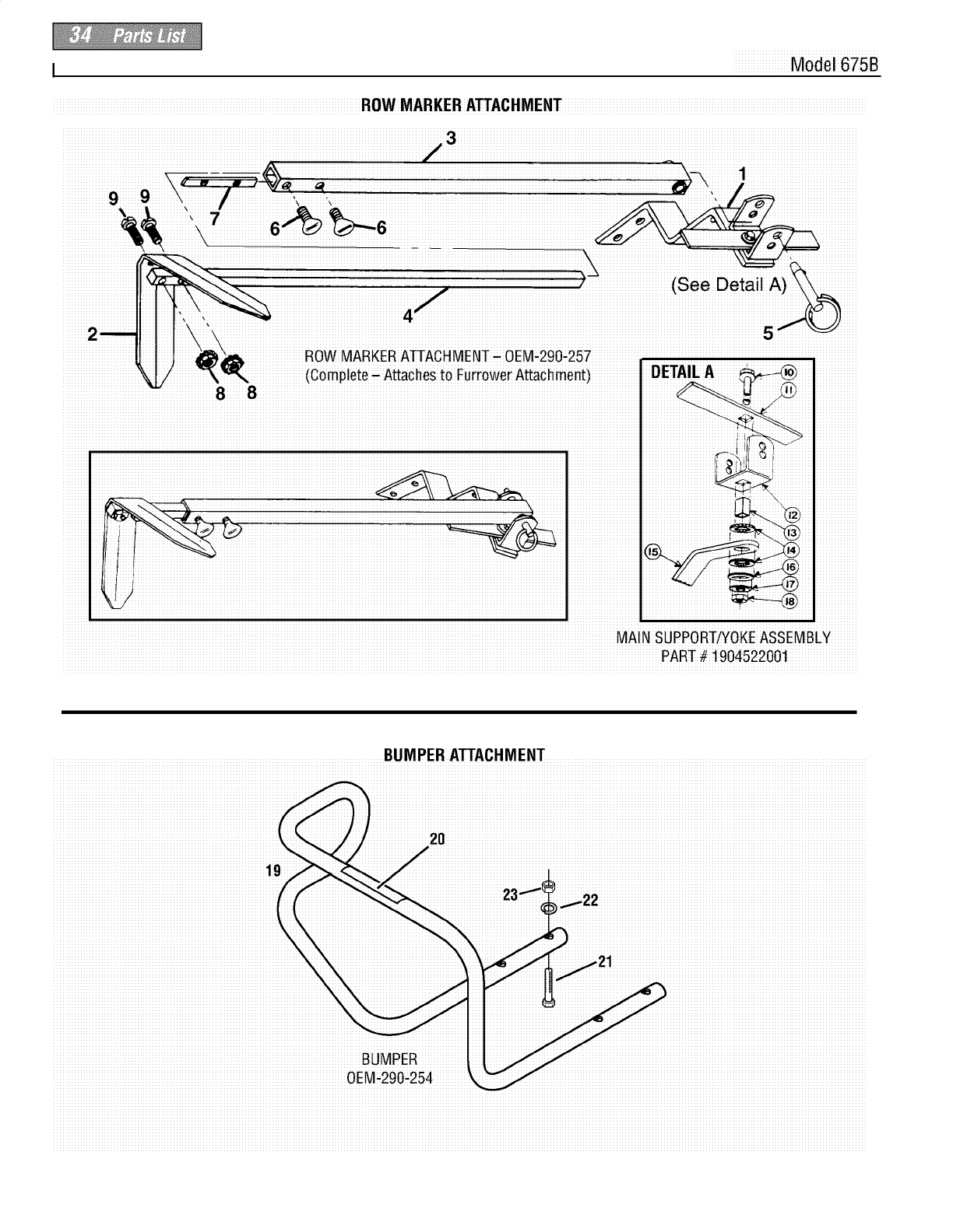
I Model 675B
iiiiiiiiiiiiiiiiiiiiiiiiiiiiiiiiii _i_ iiiiiii iiiiiiiiiiiiiiiiiiiiiiiiiiiiiiiiifi3iiiiiiiiiiiiiiiiiiiiiiiiiiiiiiiiiiiiiiiiiiiiiiiiiiiiiiiiiiiiiiiiiiiii_i iiiiiiiliiiiiiiiiiiiiiiiiiiiiiiiiiiiiiiiiiiiiiiiiii iiiiiiiiiiiii
II
}_. (Completea Attachesto FurrowerAttacflmenti
MAIN SUPPORT/YOKEASSEMBLY
PART# 1904522001
BUMPER ATTACHMENT
_iiiiiiiiiiiiiiiiiiii2_iiiiiiiiiiiiiiiiiiiiiiiiiiiiiiiiiiiiiiiiiiiiiiiiiiiiiiiiiiiiiiiiiiiiiiiiiiiiiiiiiiiiiiiiiiiiiiiiiiiiiiiiiiiiiiiiiiiiiiiiiiiiiiiiiiiiiiiiiiiii
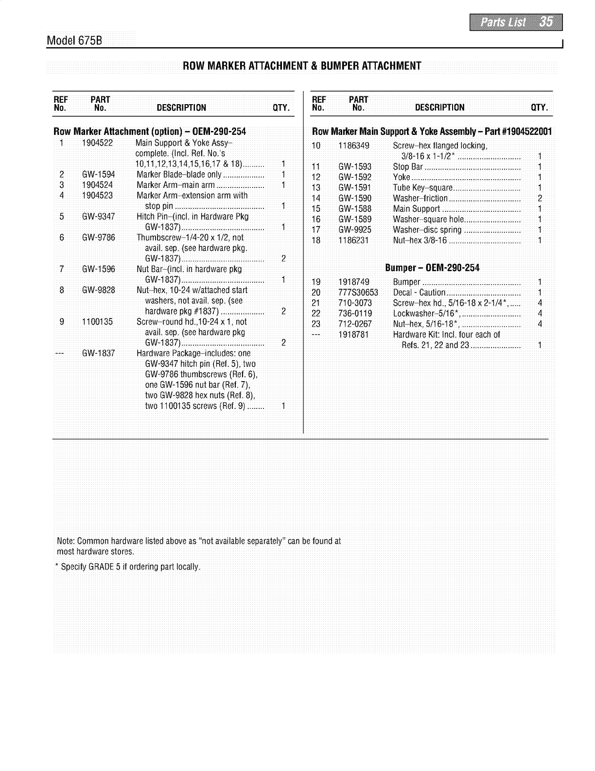
Model 675B I
ROW MARKER ATTACHMENT&BUMPER ATTACHMENT
N_iiiiiiiiiiiiiiiiNo;iiiiiiiiiiiiiiiiiiiiiiiiiiiDESCR_NiiiiiiiiiiiiiiiiiiiiiiiiiiiiiiiiiiiQ]-Y_iii N_iiiiiiiiiiiiiiiNo_iiiiiiiiiiiiiiiiiiiiiiiiiiiiDESCR_P-_NiiiiiiiiiiiiiiiiiiiiiiiiiiiiiiiiiiiQ_]-Yiiiii
RowMarker Attachment(option)-0EM-290,254, RowMarkerMain Support& YokeAssembly-Part #1904522001
1 1904522 Main Suppod & ¥0ke ASSy 10 1186349 screw_hex flanged ioCking
€omPieie (inCL Ref No. s
10,1!,12i13;!4;!5;!6i17&!8)i.iiiii.i; ! il GW_1593 S_opBar ..... i.. i.. i.. i...., i 1
2 GWi1594 MarkeiB!ade_bladeon!Y ......... ! i2 GW1592 Yol_e i.. i.. i. ii. ii. i.. i.. i.. i 1
3 1904524 MarkerArm_main arm:..::i:.i::i:.i::i:.i: 1 i3 GWi_59_ Tube KeY squaie ............... 1
4 1904523 MarkerArm_xtension arm with !4 GW1590 Washe[_#iCfion i. i. i.. i.... i 2
i5 GW_t588 MainSuppo_i. ii. ii. i.. i.. i.. i 1
5 GWi93_7 Hi!oh Pin (!nO in HardwarePkg l i 6 GWi 589 Washer_square holei:i...i
GWq 83Z)..iii...iii..iii...iii...iii...iii...i 1 17 GW_9925 washer_discspring ii.i i..i i.. i.. i 1
6 GWi9786 Thumbscrew 1/4f20 × 1/2, no!' i8 1_8623i Nut hex 3}8i6 ii. ii. i.. i.. i.. 1
avail,sepi (see hardware pkg: I
GWq 837)..iii...iii..iii...iii...iii...iii...i 2
_ GW_t596 Nut Bar-(in¢i in hardware pkg Ieumper0EM_290,254
GWt1837).iiii..iiii..iiii..iiii.iiiii.iiiii.ii 1 19 1918749 Bumper .iiii..iiii.iiiii.iiiii.iiii..iiii..iiii..iii 1
8 GWi9828 Nuthe x !Of24w!attachedsta_ ' 20 777S30653 DeCaiiCaution _
washers, no! aVai!isepi (see I 21 7_0i3073 SCrew heXhd ; 5/i6i18 × 2il/4÷ ..4
hardware pkg #t837).iii...iii...iii...i 2 22 736_01t9 Lockwasher_5it6_;iiiii.iiii..iiii..iiii..iii 4
9 1100135 Sc!ew_round hdi 10i24 X 1 not I 23 7i2;0267 Nut heXiSii6i18_, 4
aVai!,sepi (see hardware pkg _:_ 1918781 Hardware Kiti in¢i four each of
GWi_83Z).. 2 1 Refs21i22and 23i. i.. i.. i.. 1
_÷_ GW_t837 H_rdwaro Package-includes: one I
GW:934Z hitch pin (Refi 5); two I
GW,9786 thumbscrews (Refi 6); I
one GWd 596 nut bar (ReL 7)i I
two GW_9828 he× nuts (ReL 8); I
two t 100135 screws (Rofi 9)iiiii.ii !
Note: Common hardware !isted abow as i'not available separate!y'i can be found at
most hardware storesi
, speci_ GRADE5if ordering partlocallyi
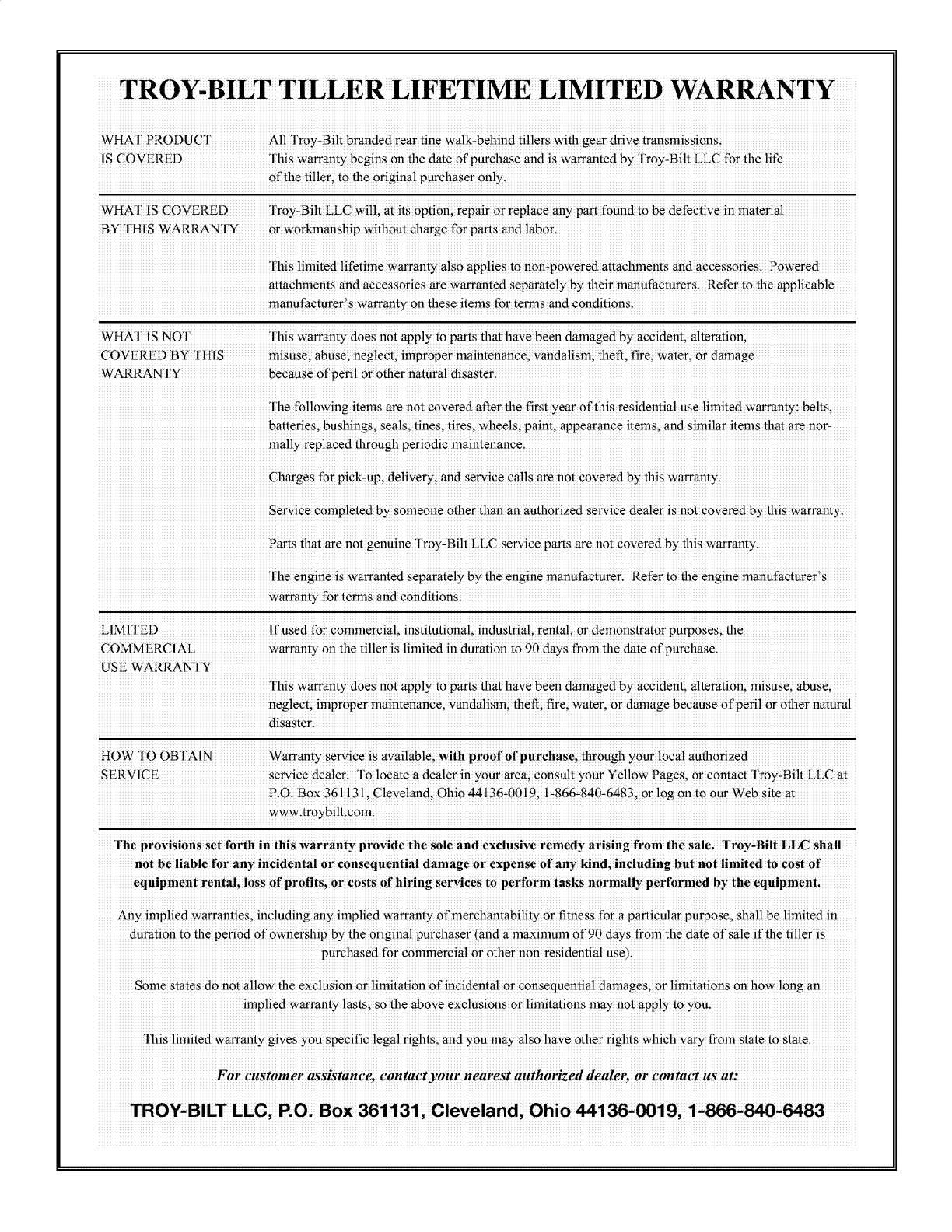
TROY-BILT TILLER LIFETIME LIMITED WARRANTY
WHAI PRODUCI' M! rr0y-Bi!t branded rear tine wa!k-behind tillers wifll gear drive _ansmiss!onsi
is COVERED INS wa_anty begins on the date of purchase and is warranted by "1roy, Bilt LLC for the life
of the tiller; to the original purchaser onlyi
WHAI IS COVERED l'my=Bilt LLC will; at its option; repair or replace any _rt found to be defective material
By IHIS WARP-AN Iy or w0rkmanship withnu t charge for pa_s and !ab0ri
ins limited lifetime warranty also appliesto non,powered attachments and accessoriEs. Powered
attachments and accessories are warranted separate!y by their manufacturers. Refer to the applicable
manufacturer's warranty on these items for terms and conditions.
WHAI IS NOr rhiS warranty doeS not apply to parts that have been damaged bY accident; alteration;
COVERED By IHIS misuse; abuse; neglect; improper maintenancei v_da!ism; the_; fire;water;0r damage
WARRAN'I Ybecause of peril or other naural disasteri
l'he following items are not covered after the first year of this residential use limited warranty: belts;
batteries; bushings; seals; tines;tires; wheels; paint, appearance items; and similar items that are no>
ma!!y rep!aced thmugh periodic maintenance;
Charges for Pick-up; de!iveryi and see;ice Callsare not €0Vered bY this wa_antY.
service completed by someone other than an authorized service dealer is not c0Vered bYthis warranty{
Parts that are not genuinelroy-BiltLLC service pa_s are n0t covered by this warrantyi
The engine is Wa_anted separately by the engine manufactureri Refer t0 the engine manufacturer's
warranty for temls and c0nditi0ns4
LIMI 1ED If Used for c0mmercial; instiiuti0nal; industrial;rental; or dem0nStrator pu_0ses; the
COMMERCIAL warranty 0nthe ti!!eris limited in duration rag0 claysfrom the date 0f purchasei
USE WARRAN 1Y
:Ibis Warranty does not apply to parts that have been damaged by accident; alteration; misusei abUsei
neg!ect;improper maintenance; vanda!ism; theft; firei water, or damage because of pefi! or Other natura!
disasteri
HOW TO OB I'AIN Wa_anty Service is available;With proof Of purchases thrOUgh your local auflmfized
SERVICE service dea!er; l o !ocate a dea!er in your area; consult your Ye!!ow Pages, or contact Tr0y-Bi!t LLC at
PiO. BOX361131; Cleveland; Ohio 44136.0019;1.866.840.6483; or log on to our Web site at
www.tmYbi!t.€om{
°rhe provisions Set forth in this warranty provide the s01e and exclusive remedy arising from the salei °rroy,Bilt LLC shall
not be l!able for any incidental or consequential damage or expense of any _ndi including but not limited to cost of
equipment rentali 10ss of profitsi or costs of hiring services t0 perform tasks normally performed by the equipmen!,
Any implied warranties; !nc!uding any implied wa_anty of merchantability or fitness for apa_icular purpose, shall be limited in
duration to file peri0d Ofownership by the origina! purchaser(and a maximum of 90 days from the date of sa!e if _e ti!!er is
purchased for c0mmercia! or other n0n-residentia! use)i
some states do not allow file exclusion or limitation of incidental or consequential damages; or limitations on how long an
implied warranty l_tsi so the above exclusi0ns or limitations may n0_apply to you.
l'his limited Warranty gives you s_cific legal rights; and you may dis0 have other rights Which Vary from state t0 staei
For customer assistance, contact your nearest authorized &Met; or contact us at:
TROY-BILT LLCi P.Oi Box 361131; ClevelandiOhio _136,_19i 1,866,_0,6483
