True Fitness 600Ea Users Manual Elliptical Service
750E af07bc9a-8c41-4705-8fc2-b50208a0ca9a
750E to the manual af07bc9a-8c41-4705-8fc2-b50208a0ca9a
2015-02-03
: True-Fitness True-Fitness-600Ea-Users-Manual-460432 true-fitness-600ea-users-manual-460432 true-fitness pdf
Open the PDF directly: View PDF ![]() .
.
Page Count: 50

True Fitness Service
Manual
Elliptical Trainers
750E
750EA
600EA
True fitness technology, Inc. makes no representations or warranties regarding the
contents of this manual. We reserve the right to revise this document at any time or
to make changes to the product described within it without notice or obligation to
notify any person of such revisions or changes.
© 2004, True Fitness, Inc. All rights reserved. Printed in the United States of
America.
865 Hoff Road. O’Fallon, MO 63366. 1-800-426-6570. Fax 636-272-3026.
www.truefitness.com
Revision 9/2004
Recommended Tool List
Technicians will need at minimum the tools listed below to work on the True Fitness
equipment covered by these procedures.
Electrical Tools
A multi meter capable of testing voltage, amperage, resistance and continuity.
Outlet tester with a grounding indicator.
Wire stripper, cutter and crimper.
Flashlight
Mechanical Tools
Screwdrivers:
#1 Phillips, #2 Phillips, large flat blade, small flat blade, short handled flat blade.
Metric hex-key (Allen wrench) set.
Metric socket set and ratchet with 6mm to 19mm sizes and 21mm and 34mm sizes.
Metric combination wrenches with 4mm to 21mm sizes and a 27mm El crank.
Snap ring pliers, both internal and external.
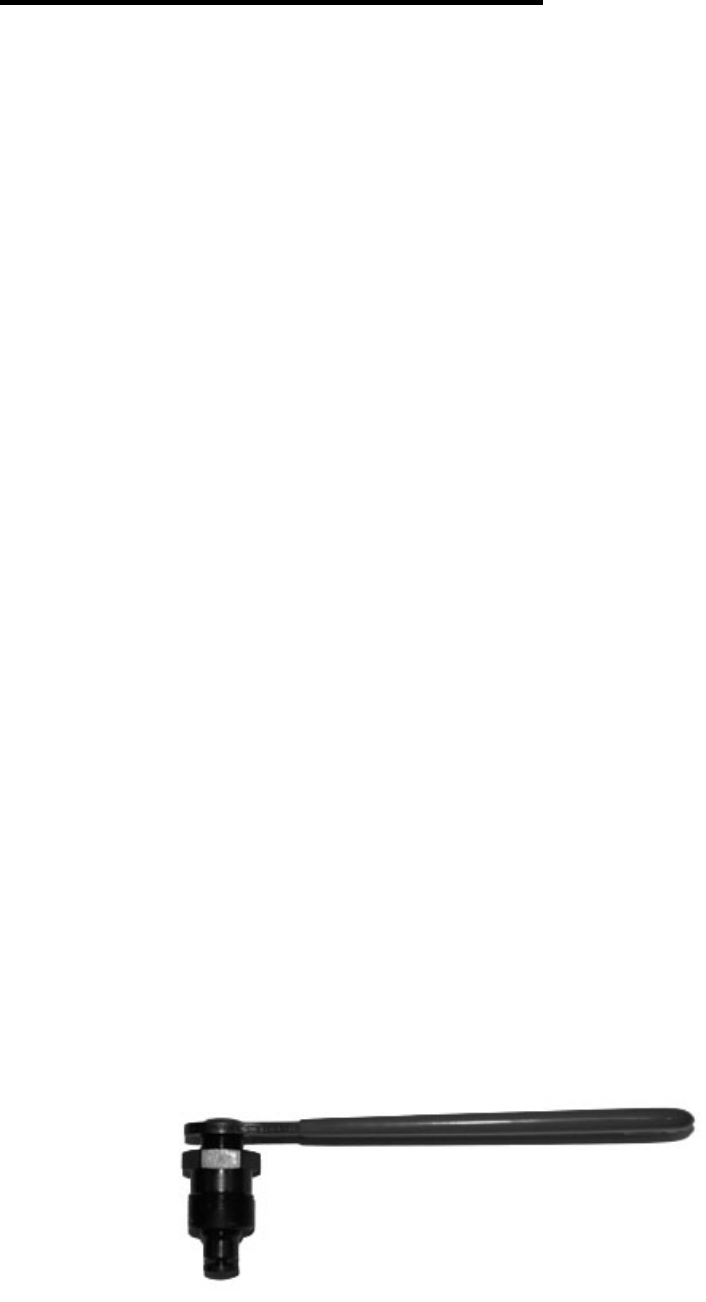
True Fitness Elliptical 2 19/32 Wrench pn: 90361501
Rubber mallet.
Channel lock pliers or standard pliers with a jaw opening of 2 9/16” for use in removing
and tightening sleeve nuts.
Needle nose pliers.
Crescent wrench
Special Tool
Bicycle crank puller
Park Tool USA CCP-2

True Fitness
Elliptical
Service Manual
START
Symptom guide
Wiring Diagrams
Parts Manual
Removal and Replacement Procedures
Page 1
Test Mode *750 ONLY Procedure
D
I
A
G
N
O
S
T
I
C
S
To Enter Diagnostic
Mode
Console / Display
Output
RPM
Console Key Input
Contact Heart Rate
DA (Resistance)
Exit Diagnostics
•
Press and hold the “Start” key as you
begin pedaling.
• Continue pedaling throughout the test.
-------
• Press “Enter” key – initiates the second
LED function test.
• Press “Enter” key again –all LED’s
should be on.
--------
• Press “Enter” key – RPM’s displayed in
the far right window.
--------
• Press “Enter” key –A beep should sound
when each key is pressed.
--------
• Press “Enter” key. Hold both handle
pick-ups. Heart symbol will flash and
readout will display.
-------
• Press “Enter” key – Press + to increase
resistance and – to decrease resistance.
• To quit diagnostics press “Enter” key or
stop pedaling and the unit will reset.
Support Services 800-883-8783 Mon-Fri 8:30am-5:00pm Central Time Zone Fax: 636-272-7148
Page 2

SYMPTOM GUIDE
600EA
Resistance Malfunction . . . . . . . . . . . . . . . . . . . Page 13
No Display. . . . . . . . . . . . . . . . . . . . . . . . . . . . . . Page 14
No Speed Reading. . . . . . . . . . . . . . . . . . . . . . . . Page 15
750E,750EA
No Resistance . . . . . . . . . . . . . . . . . . . . . . . . . . . . Page 5
Heavy Resistance . . . . . . . . . . . . . . . . . . . . . . . . Page 6
No Display . . . . . . . . . . . . . . . . . . . . . . . . . . . . . . Page 7
All Models
No Contact Heart Rate . . . . . . . . . . . . . . . . . . . . Page 8
No Polar Heart Rate . . . . . . . . . . . . . . . . . . . . . . Page 9
Vibration from Drive Train . . . . . . . . . . . . . . . . . . . Page 10
Knocking in Rhythm of Pedaling . . . . . . . . . . . . . Page 11
Squealing / Screeching from
Aluminum Extrusion Tubes . . . . . . . . . . . . . . . . . Page 12
Page 3
Symptom Probable Cause Corrective Action Recommended Tools
NO RESISTANCE
750E, 750EA
Console Set
Defective Cables
Power Resistance
• Remove console bolts to access 7-pin
connector. Do not disconnect console
set.
• Enter DA (resistance) test mode.
(Page 3).
• Press + key to force .7 VDC out of
panel.
• Set meter for DC Volts. Measure
between #2 pin and #4 pin at 7- pin
connector.
• Is .7 VDC present? No- replace console
set. If present, continue on.
--------
• Remove right mast cover and handlebar.
• Measure between the #2and #4 wires at
the 7 –pin connector on the lower board.
• Is .7 VDC present? No- replace cable
for console. If present, continue on.
--------
• DO NOT PEDAL.
• Set meter for resistance. Disconnect 3-
pin connector at the lower control board.
Measure resistance between #1 pin and
#3 pin.
• Resistance should be 10 ohms, +/- 1
ohm.
• If less than 10 Ohms- replace power
resistance. If resistance checks OK,
continue on.
--------
• DO NOT PEDAL.
• Remove main body cover, set meter for
continuity.
• Disconnect brake cable from brake and
lower board.
• Check continuity of all wires in cable.
• Check for cross continuity- this would
indicate multiple shorts in the cable.
• No continuity? Replace Brake cable.
• Yes continuity? Replace lower board.
Note:
Multi-meter
Support Services 800-883-8783 Mon-Fri 8:30am-5:00pm Central Time Zone Fax: 636-272-7148
Page 4
You must pedal at least
30 RPM when
performing any voltage
test. You may require the
assistance of another
person when performing
voltage checks.
Symptom Probable Cause Corrective Action Recommended Tools
HEAVY
RESISTANCE
750E, 750EA
Foreign Objects
Console Set
Defective Cables
Lower control
Board/ Brake
• Check for foreign objects causing
mechanical binding.
• Remove foreign objects.
--------
• Remove the console set.
• Disconnect the 7-pin connector from the
back of the console set.
• Pedal.
• Resistance normal? Replace console set.
--------
• Remove right side handle bar assembly
and mast cover.
• Disconnect 7- pin connector from the
lower control board.
• Pedal.
• If resistance is normal- replace cable for
console.
--------
• Remove main body cover.
• Disconnect 3- pin connector from the
brake.
• Resistance still heavy- Replace brake.
• Resistance normal
• Check brake cables for cross continuity.
• Replace lower control board.
Multi-meter
Page 5
Support Services 800-883-8783 Mon-Fri 8:30am-5:00pm Central Time Zone Fax: 636-272-7148
Symptom Probable Cause Corrective Action Recommended Tools
No Display
750E, 750EA Console Set
Brake
Defective Cable
Console Cable/
Lower Control
Board
• Remove console set bolts. Verify good
connection at the back of the console
set. Set meter for DC volts
• Pedal.
• Measure between #1 and #4 wires for
5.5 – 7.5 VDC.
• Is required voltage present?
• If yes- replace console set. If not,
continue on.
--------
• Remove right side bar assembly, right
mast cover and main body cover.
• Disconnect 3- wire connector at brake.
• Set meter for AC volts.
• Pedal.
• The voltage should increase as pedaling
increases.
• Is minimum voltage 9 VAC @ 30
RPM?
• If No- replace Brake. If yes, continue
on.
--------
• Remove right side bar assembly, right
mast cover and main body cover.
• Disconnect 3- wire cable from brake and
lower control board.
• Set meter for continuity.
• Check all 3 wires in cable for continuity.
• No continuity? Replace cable
----------
• Set meter for DC volts. Reconnect
cable to brake and lower control board.
• Pedal.
• Measure for 5.5 – 7.5 VDC between #1
and #4 wires on 7- pin cable for the
console at the lower control board.
• Voltage is present? Replace cable for
console.
• Voltage not present? Replace lower
control board.
Note:
You must pedal at least
30 RPM when
p
erforming any voltage
test. You may require the
assistance of another
p
erson when performing
voltage checks.
Multi-meter
Support Services 800-883-8783 Mon-Fri 8:30am-5:00pm Central Time Zone Fax: 636-272-7148
Page 6

Symptom Probable Cause Corrective Action Recommended Tools
NO CONTACT
HEART RATE
750E, 750EA
Dirty Sensors
Console Set/
Wiring
Wire Connections
Note:
You must pedal at least
30 RPM when
p
erforming any voltage
test. You may require the
assistance of another
p
erson when performing
voltage checks.
Multi-meter
Double sided tape
Support Services 800-883-8783 Mon-Fri 8:30am-5:00pm Central Time Zone Fax: 636-272-7148 Page 7
•
Verify hand pulse sensors are clean.
--------
• Set meter for continuity.
• Remove Console set.
• Check for continuity in both sets of
hand pulse sensors between the console
set and hand pulse sensor plates.
• If continuity is OK – Replace Console
set. If no- continue on.
--------
• Check wire connections @ handlebar
console mast joint
• Check connections of wires to hand
pulse sensor by removing hand pulse
sensor plates.
• To remove hand pulse sensor plates
carefully pry under one end to free them
from the plastic handgrips.
• Bad connections? - Reconnect/ Replace
bad wires.
• Recheck continuity.
Symptom Probable Cause Corrective Action Recommended Tools
NO POLAR
HEART RATE
750E, 750EA
600EA.
Control Panel
Defective Cables
• Attach heart rate simulator around chest
or use Polar simulator.
• Do not touch the hand pulse sensors.
• Start pedaling
• Check display for heart rate.
--------
• Does console display heart rate with
chest strap?
• Does console display heart rate with HR
simulator?
• If unit responds with simulator and not
chest strap then replace chest strap.
• If unit does not respond with strap or
simulator then replace Console set.
Note:
You must pedal at least
30 RPM when
p
erforming any voltage
test. You may require the
assistance of another
p
erson when performing
volta
g
e checks.
Polar Heart Rate
Simulator
Excessive radio,
electromagnetic or
audible noise can
cause poor heart rate
reception.
Support Services 800-883-8783 Mon-Fri 8:30am-5:00pm Central Time Zone Fax: 636-272-7148
Page 8
Symptom Probable Cause Corrective Action Recommended Tools
VIBRATION
FROM DRIVE
TRAIN
750E, 750EA
600EA.
Belt Tension
Brake Vibration
Wobbling Pulleys
Shaft Vibrations
Vibrating Bearings
• Remove main body cover.
• Check poly V- belt for bumps- if bump
exists, replace the belt.
• Check for proper belt tension. Belt
should be very tight, grasp belt in the
middle and twist, you should only be
able to twist it 90 degrees.
--------
• Pedal.
• Very carefully check brake for
vibration, use caution as the moving
arms cross in front of the brake.
• If vibration is found- tighten bolts and
/or replace brake.
--------
• Does pulley of either poly V- wheel
wobble? If so then tighten bolts.
• If tightening does not resolve- replace
damaged poly-v- wheels.
--------
• Check shaft assemblies. Check for
endplay on shaft assemblies.
• Check for vibration in shaft assemblies
by applying screwdriver to frame at
shaft bearings.
• If vibration is found- replace shaft
assembly.
Caution: When
checking for vibrations
take care to not get
caught by the pulleys,
belts and moving parts.
--------
• Check belt tensioned.
• Use screwdriver method to check
bearings on wheel shaft.
• Replace tension wheel assembly.
Long handled
screwdriver
Support Services 800-883-8783 Mon-Fri 8:30am-5:00pm Central Time Zone Fax: 636-272-7148 Page 9

Symptom Probable Cause Corrective Action Recommended Tools
KNOCKING IN
RHYTHM OF
PEDALING
Crank and Shaft
Swing Arm Bearings
• Remove main body cover.
• Check crank arm nuts for tightness.
• Is noise coming from the crank area
• If yes – remove crank, check shaft and
crank for damage.
• Replace parts as needed.
--------
• Check the moving arm bearing for
noise.
• Tighten nut and check for noise.
• If noise continues – replace moving arm
assembly.
Multi-meter
14mm socket
21mm socket
27mm socket
Support Services 800-883-8783 Mon-Fri 8:30am-5:00pm Central Time Zone Fax: 636-272-7148
Page 10
Symptom Probable Cause Corrective Action Recommended Tools
SQUEALING /
SCREECHING
FROM
ALUMINUM
EXTRUSION
TUBES
750E, 750EA,
600EA.
Cleaning Aluminum
Extrusion Tubes
Checking Rollers
Moving Arm Travel
• Remove aluminum extrusion tubes.
• Clean tracks with general purpose
cleaner. DO NOT USE PETROLIUM
BASED CLEANERS – it will degrade
the rollers.
• Clean roller.
-------
• Check rollers for bumps and flat spots.
• Do rollers spin freely?
• If rollers do not spin freely – replace
rollers.
--------
• Do the moving arms run straight down
the aluminum extrusion tubes?
• If no – loosen nut on cubic joint.
• If no help – replace moving arm
assembly.
Non- petroleum based
cleaner. (For example:
Simple Green)
Support Services 800-883-8783 Mon-Fri 8:30am-5:00pm Central Time Zone Fax: 636-272-7148 Page 11
Symptom Probable Cause Corrective Action Recommended Tools
RESISTANCE
MALFUNCTION
600EA
Console Set
Lower Board / Brake
Cable
Brake Coil
Console Cable
• Remove console bolts to access 7-pin
connector. Do not disconnect console
set. Set meter for DC Volts. Measure
between pin 1(red) and pin 5(blue) at 7-
pin connector.
• Enter DA (resistance) test mode. Page
SG-1.
• Press + key to force .9 VDC out of
panel.
• Press + to check voltage at all levels. Is
voltage displayed on meter
approximately the same as voltage
displayed in heart rate window? No-
replace console set. Yes, continue on.
--------
• Remove main body cover & locate the
cable connecting the brake and the
lower control board. Set meter to DC
volts.
• Check DC voltage between pins 2 and 4
of the power supply
• Is voltage is same as shown in heart rate
window?
• If NO – go to console cable.
• Check voltage at the 2-pin connector at
the brake. Press + to increase resistance
and voltage.
• Does the voltage start at 3.7 and
increase to 30 VDC? If no- check
continuity of cable. If cable is broken
replace it, if cable is good – replace the
lower board.
--------
• Set meter to resistance and check the
coil. Coil resistance should be 15 ohms,
+ or – 2 Ohms. If not then replace the
coil.
--------
• Set meter to resistance; perform
continuity check on wire harness.
• Check for cross continuity.
• Broken wires? Replace cable.
Note:
You must pedal at least
30 RPM when
p
erforming any voltage
test. You may require the
assistance of another
p
erson when performing
volta
g
e checks.
Multi-meter
Support Services 800-883-8783 Mon-Fri 8:30am-5:00pm Central Time Zone Fax: 636-272-7148
Page 12

Symptom Probable Cause Corrective Action Recommended Tools
NO DISPLAY
600EA
Power Issues
Control Panel
Power Supply
Cables
• Set meter to AC voltage and test wall
outlet to 120 VAC.
• Turn power switch on
• Does power switch lamp come on?
• Yes – go to control panel.
• No- remove rear cover.
• Check voltage input to switch, is it 120
VAC? If yes – replace switch. If no –
continue on.
• Check voltage at end of power cord.
• No voltage? Replace cord.
• Check fuse in power inlet.
• Replace fuse or replace power inlet and
wires.
--------
• Check connection to the display.
• Reseat connection.
• Set meter to DC volts, unplug display
and check voltage between pin 1and pin
2.
• If 12VDC is present – replace control
panel.
--------
• Check voltage between pin 2and pin 3at
the power supply.
• If 12 VDC present – replace power
supply.
--------
• Perform a continuity check on the cables
leading to the control panel.
• Replaced damaged cables.
Multi-meter
Page 13
Support Services 800-883-8783 Mon-Fri 8:30am-5:00pm Central Time Zone Fax: 636-272-7148

Symptom Probable Cause Corrective Action Recommended Tools
NO SPEED
READING
600EA
Console Assembly
RPM Sensor
Defective ECB
Control Board
• Remove monitor bolts. Move the swing
arms until the magnet is in front of the
sensor.
• Set meter for DC volts. Check voltage
between pin 3 and pin 1 at console
assembly with cable connected.
• Move swing arms. When magnet is
over the pickup the voltage should be 0
VDC. When the magnet is not over the
pickup, the voltage should be 5 VDC.
• Does the voltage alternate between 0
VDC and 5 VDC? If yes – replace
console assembly.
--------
• Turn power off, remove rear cover
• Disconnect the sensor connector. Set
meter for resistance.
• Check resistance at the 2 pins of the
connector. Slowly move the swing arms
to rotate the wheel.
• Does the meter show continuity when
the magnet is over the pickup? If no –
replace the sensor.
--------
• Perform a continuity and contact check
on the console wire.
• Replace defective wire.
Multi-meter
Support Services 800-883-8783 Mon-Fri 8:30am-5:00pm Central Time Zone Fax: 636-272-7148
Page 14

WIRING DIAGRAMS
TAE 600 Page 16
TAE 750 Page 17
TE 750 Page 18
Page 15
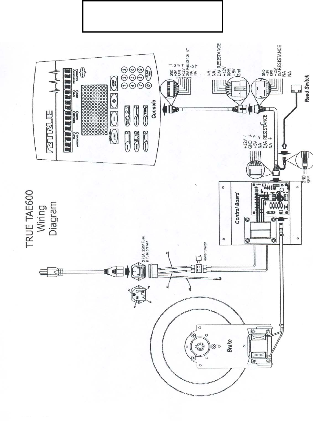
TRUE TAE 600
WIRING DIAGRAM
Page 16
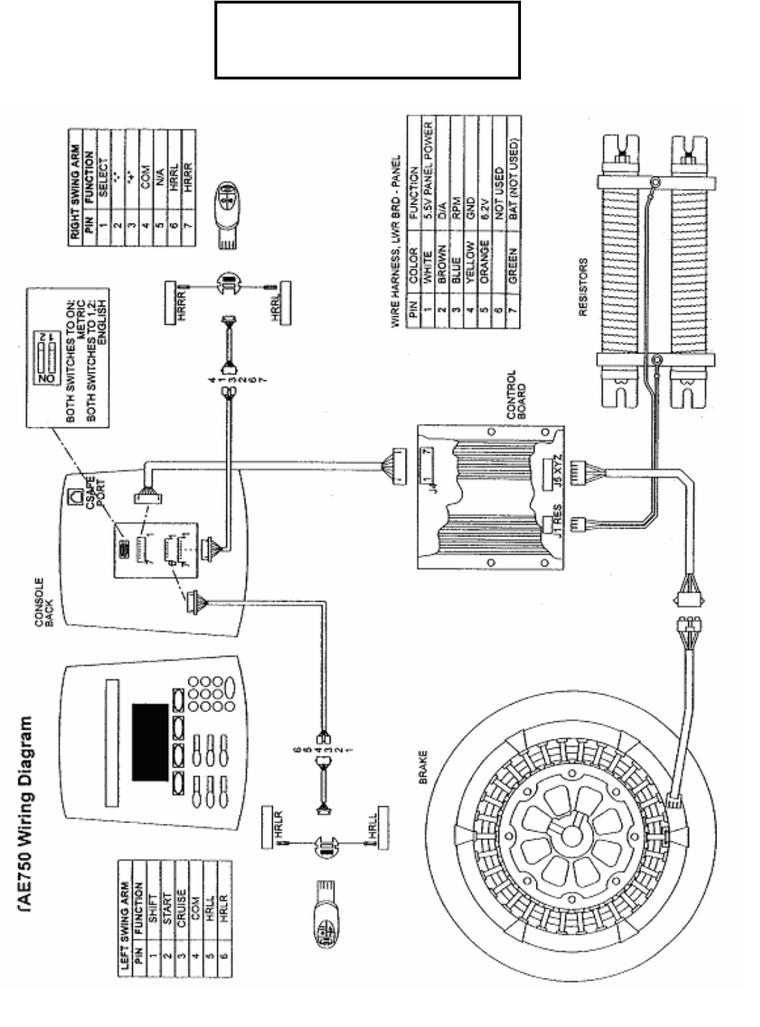
Page 17
TRUE TAE 750
WIRING DIAGRAM
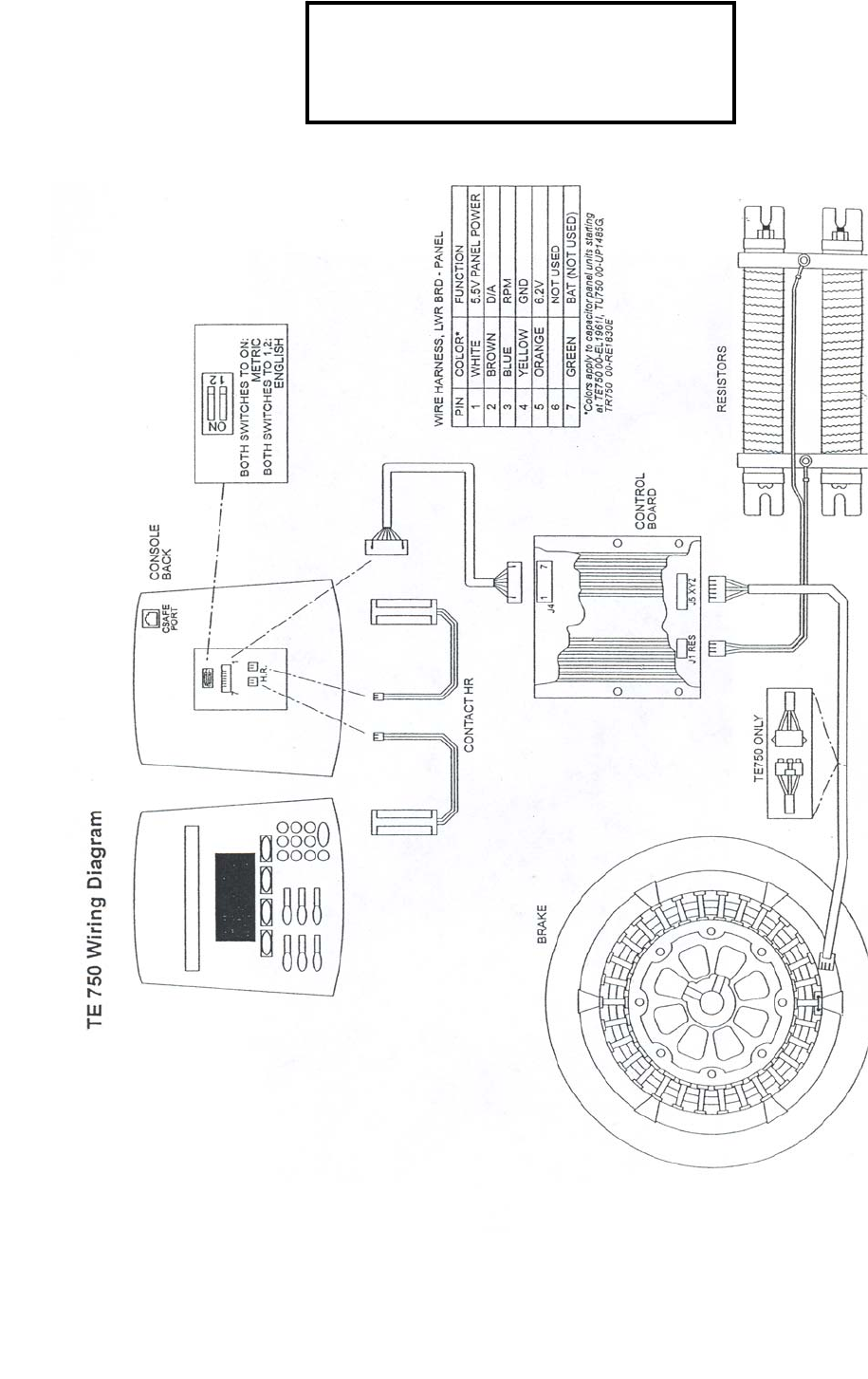
Page 18
TRUE TE 750
WIRING DIAGRAM

True Armed
Elliptical 600B
Exploded Diagram Page 20
Parts List Page 21
Page 19
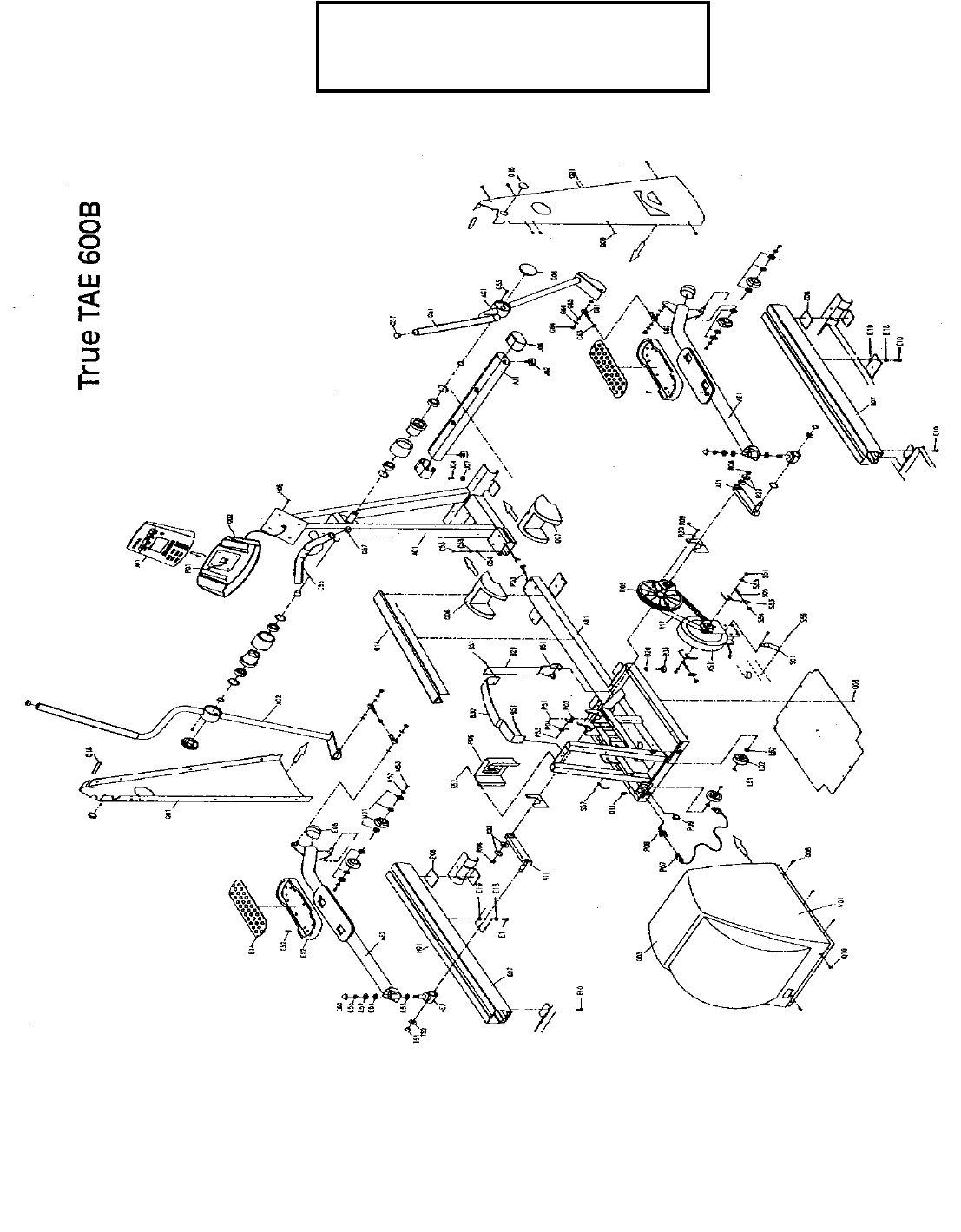
TRUE TAE 600
PARTS DIAGRAM
Page 20

TAE 600B
REF # PART# DESCRIPTION QTY
AC1 7TSZEP42CSM CONSOLE MAST ASSY 1
AE1 7TSZEP17PAM-6R1 RIGHT ARM ASSY 1
AE2 7TSZEP17PAM-6L1 LEFT ARM ASSY 1
AE3 7TSW0306011A MVG ARM PIVOT 2
AG1 7TSZEP25HDB-R HANDLEBAR ASSY RH 1
AG2 7TSZEP25HDB-L HANDLEBAR ASSY LH 1
AJ1 7TSZEP07FST FRNT STBL ASSY 1
AN1 7TS12325001 CONSOLE ASSY 1
AS1 7TMD0208010C BRAKE ECB SET 1
AT1 7TS08317001 CRANK ARM 2
B28 7TMB0301002 FOOT PAD WASHER 2
B29 7TMJ1390003E VERTCL SPT PLATE 1
B30 7TMJ1390004 UPPER SPT PLATE 1
B31 7TMB0302002 FOOT PAD 2
B51 7TME0102021 SCREW CVR SPT 6
C53 4
C54 4
C55 4
C56 7TMB0401050A STATIONARY BAR 2
E05 7TMB0609025 STABILIZER BAR 2
E07 7TSZEP25RAL ARM TRACK 1
E08 7TMB0674006 RUBBER PLATE TRK 2
E10 7TME0112024 OVAL HEX SKT TRK 8
E12 7TMB0206002C FOOT PLATE 2
E14 7TMB0304011 FOOT PLATE INSERT 2
E18 7TME0502027 FLAT WASHER 8
E19 7TME0501007 SPRING WASHER 8
E52 7TME0102027 SCREW FOOTPLATE 8
E54 7TME0505037 TEFLON WASHER 2
E55 7TME0204026 NYLON NUT 2
E56 7TME0505020 TEFLON WASHER 2
E57 7TME0502006 FLAT WASHER 2
E60 7TMB0609063B MVG ARM JOINT 2
G08 7TMB0678005A END CAP SWING ARM 2
AC1 7TSP0302022A CONSOLE MAST 1
G51 7TMB0401058A FOAM GRIP UPPER H/BAR 2
G55 7TME0104057 SCREW RND HEX 8
G57 7TMB0609018 HNDLBR END CAP 4
G61 7TMD0508001 CONNECTOR ARM A 1
G62 7TMD0508002 CONNECTOR ARM B 1
G63 7TME0101042 CONNECTOR ARM NUT 1
G64 7TME0204007 NYLON NUT 4
G65 7TME0506013 WAVE WASHER 8
G66 7TME0508011 WASHER CONNECTOR ARM 8
J02 7TMB0304006 FT LEVELER 2
J04 7TME0112024 SCREW FT STABILIZER 2
J06 7TMB0609035 END CAP STABILIZER 2
J07 7TMJ3344001 RAIL CVR ANCHOR 22
L02 7TMB0103002 MOVING WHEEL 2
Page 21

L51 7TME0204005 NYLON NUT 2
L52 7TME0502030 FLAT WASHER 2
M01 7TS11317001 WHEEL ASSY MVG ARM 1
M52 7TME0502026 FLAT WASHER 4
M53 7TME0112074 SCREW OVAL HEX SCKT 4
N05 7TME0104055 SCREW CNTRL PNL 4
P01 7TMC0501045D CONSOLE WIRE UPPER 1
P02 7TMJ1802001 SENSOR BRKT 1
P03 7TMC0522004 CONSOLE WIRE LOWER 1
P04 7TMC0510039B RPM SENSOR W/WIRE 1
P06 7TMC0203006B CONTROL BOARD 1
P07 7TMC0504042 POWER CORD 1
P08 7TMC0703019A POWER SOCKET 1
P09 7TMC0701002 POWER SWITCH 1
P51 7TME0102021 RPM SENSOR SCREW 1
P53 7TME0108004 SCREW OVAL TAPPING 2
Q01 7TMB0202036A PEDESTAL SIDE CVR 2
Q02 7TMB0601005 WATER BTL HLDR 1
Q03 7TMB0222005A MAIN CVR 1
Q06 7TMB0246001 RAIL CVR LH 1
AC1 7TSP0302022A CONSOLE MAST 1
Q07 7TMB0246002 RAIL CVR RH 1
Q08 7TME0121005 MAIN CVR 19
Q09 7TME0107030 PEDESTAL CVR 14
Q10 7TME0107013 MAIN CVR 6
Q11 7TME0701001 C CLIP MAIN CVR 2
Q14 7TMB0627006B CORROSION CVR 1
Q15 7TMB0613010A RND PLUG RT SIDE CVR 2
Q16 7TMB0678018A RECTANGULER PLUG 1
R05 7TMJ3305016A POLY V WHEEL 1
R06 7TME0208006 NUT HEX HEAD 2
R09 7TME0104047 FLYWHEEL 6
R17 7TMD0603005 POLY V BELT 1
R20 7TME0504006 WASHER 6
R22 7TME0508004 WASHER 4
S01 7TMJ1374012A ECB CONNECTION PLATE 1
S05 7TME0110002 EYE-BOLT 2
S51 7TME0201012 AXLE NUT 2
S53 7TMJ1245001 BELT ADJ 2
S54 7TME0204010 BELT ADJ 2
S55 7TME0502054 AXLE NUT 2
S56 7TME0102021 BRAKE BRKT 2
S57 7TME0107013 CONTROL BOARD 5
T51 7TME0902015 CRANK PIN 2
T52 7TME0506012 CRANK PIN 2
V01 7TMG0102057B REAR CVR 2
7TME0606037C ASSEMBLY 1
Page 22

True Armed
Elliptical 750
Exploded Diagram Page 24
Parts lists Page 25
Page 23
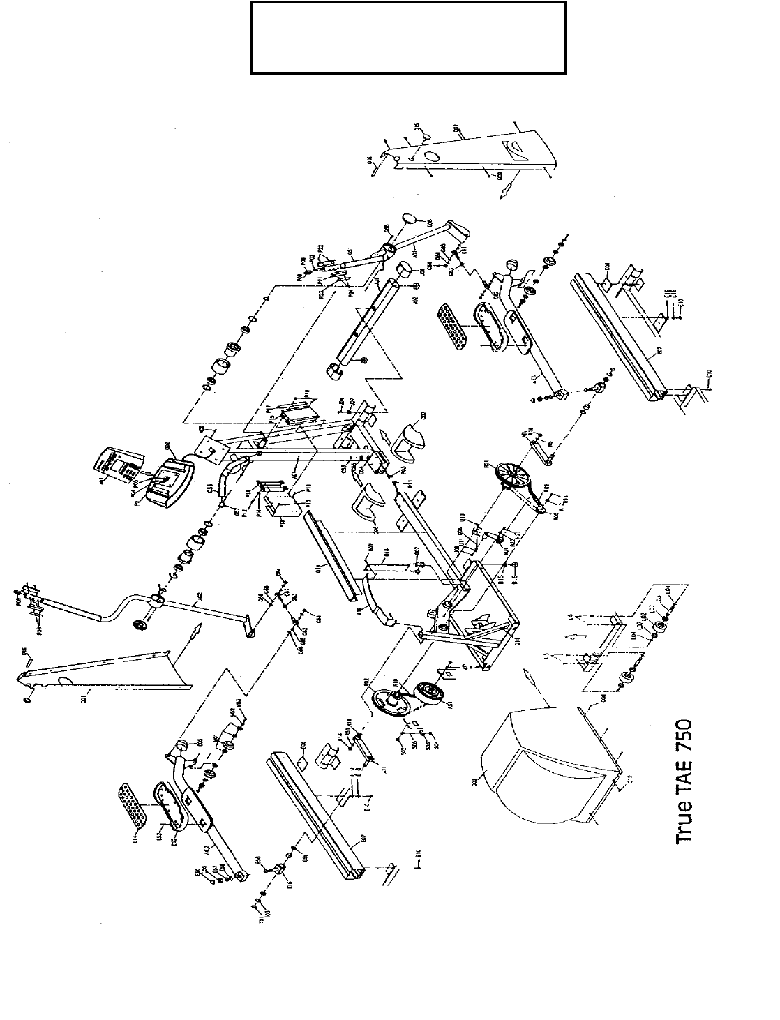
TRUE TAE 750
PARTS DIAGRAM
Page 24
TAE 750
REF. # PART # DESCRIPTION QTY
AC1 7TSZEP17CSM PEDESTAL ASSY-WITH PIVOT BEARING BLOCK ASSY 1
AE1 7TSZEP17PAM-7R1 PEDAL ARM ASSY-RH 1
AE2 7TSZEP17PAM-7L1 PEDAL ARM ASSY-LH 1
AG2 7TSZEP17HDB-R HANDLEBAR ASSY-RH(TALL) 1
AG2 7TSZEP17HDB-R1 HANDLEBAR ASSY-RH(SHORT) 1
AG3 7TSZEP17HDB-L HANDLEBAR ASSY-LH(TALL) 1
AG3 7TSZEP17HDB-L1 HANDLEBAR ASSY-LH(SHORT) 1
AJ1 7TSZEP07FST STABILIZER ASSY-FRONT 1
AN1 7TS12317001 CONTROL PANEL 1
AS1 7TMZD0208007 BRAKE ASSY 1
AS1 7TMD0208016B BRAKE ASSY-AFTER SERIAL # 02-EA-1102K 1
AT1 7TSZW0306007 CRANK ARM ASSY 2
AU1 7TSM0325001 BELT TENSIONER ASSY-PRIMARY 1
B07 7TME0102021 SCREW-FRAME SUPPORT 6
B15 7TMB0301002 LEVELER LOCK NUT-REAR 4
B16 7TMB0302002 LEVELER-REAR 4
B18 7TMJ1390001 COVER LOWER SUPPORT-REAR 1
B19 7TMJ1390004 COVER UPPER SUPPORT-REAR 1
C15 7TME0104165 BOLT-PEDESTAL MOUNTING 4
C16 7TME0502019 WASHER-PEDESTAL MOUNTING 4
C17 7TME0501007 SPRING WASHER-PEDESTAL MOUNTING 4
C56 7TMB0401050A GRIP-FIXED HANDLEBAR 2
E04 7TMB0206002C PEDAL PLATE (PLASTIC) 2
E05 7TMB0609025 END CAP-PEDAL ARM 2
E07 7TSZEP25RAL PEDAL ARM TRACK 2
E08 7TMB0674006 RUBBER PAD-PEDAL ARM TRACK 2
E10 7TME0112024 SCREW-TRACK MOUNTING 8
E12 7TME0102027 SCREW-PEDAL PLATE 8
E15 7TMB0304011 PEDAL PLATE COVER (RUBBER) 2
E18 7TME0502027 FLAT WASHER-TRACK MOUNTING 8
E19 7TME0501007 SPRING WASHER-TRACK MOUNTING 8
G04 7TMB06A7001 BRACKET-PULSE SENSOR 2
G05 7TME0102069 SCREW-PULSE BRACKET 4
G06 7TMJ1278001 SENSOR PLATE-PULSE 2
G07 7TME0201028 NUT-PULSE BRACKET 4
G08 7TMB0678005A END CAP-SWING ARM PIVOT 2
G51 7TMB0401059A GRIP-UPPER BODY HANDLEBAR 2
G61 7TMD0508001 SWIVAL JOINT 2
G62 7TMD0508002 SWIVAL JOINT 2
G64 7TME0204007 NYLON NUT-SWIVAL JOINT 4
G66 7TME0508011 CONE WASHER-SWIVAL JOINT 8
J02 7TMB0304006 LEVELER-FRONT 2
J04 7TME0112024 SCREW-FRONT STABILIZER 2
J06 7TMB0609035 END CAP-FT STABILIZER 2
J07 7TMJ3344001 RETAINER-RAIL COVER 2
P01 7TMC0501027 CABLE-DISPLAY 1
P02 7TMC0516021B CABLE-REMOTE SWITCH(H/BAR END) 2
P03 7TMC0535004 CABLE-BRAKE (LOWER BOARD END) 1 Page 25

P04 7TMC0516022B CABLE-REMOTE SWITCH(LH CONSOLE END) 1
P05 7TMC0516023C CABLE-REMOTE SWITCH(RH CONSOLE END) 1
P06 7TMC0535005 CABLE-BRAKE (BRAKE END) 1
P06 7TMC0712019B SWITCH-RH HANDLEBAR REMOTE
P07 7TME0204003 NYLON NUT-REISTOR MOUNTING 4
P08 7TME0102027 SCREW-RESISTOR MOUNT 7
P08 7TMC0712020B SWITCH-LH HANDLEBAR REMOTE
P09 7TME0502082 WASHER-RESISTOR MOUNT 4
P11 7TMC0203004 CONTROL BOARD 1
P12 7TMC0736002 RESISTOR 1
P17 7TMB06B8001 MOUNT-CONTROL BOARD 1
P18 7TMJ1393003 BRACKET-RESISTOR 1
P20 7TME0107037 SCREW-RESISTOR MOUNT 11
Q01 7TMB0202036A SIDE COVER SET-LEFT & RIGHT 1
Q02 7TMB0601005 BOTTLE HOLDER 1
Q03 7tszep07Fcv COVER-REAR 1
Q06 7TMB0246001 COVER-LEFT RAIL 1
Q06 7TMB0246002 COVER-RIGHT RAIL 1
Q08 7TME0102053 SCREW-REAR COVER 10
Q09 7TME0107030 SCREW-SIDE COVERS 12
Q10 7TME0107013 SCREW-REAR COVER 2
Q11 7TME0701001 C CLAMP-REAR COVER 2
Q14 7TMB0627006B COVER-CENTER FRAME MEMBER 1
Q15 7TMB0613010A PLUG-ROUND-SIDE COVER 2
Q16 7TMB0678018A PLUG-SQUARE-SIDE COVER 1
R01 7TSM0330001 SHAFT ASSY-PEDAL CRANK 1
R02 7TSM0330002 SHAFT ASSY-SECONDARY DRIVE W/SMALL POLY V WHEEL 1
R09 7TMD0604001 POLY V BELT-PRIMARY DRIVE 1
R10 7TMD0601014 POLY V BELT-SECONDARY DRIVE 1
R16 7TME0208008 NUT-CRANK ARM 2
R21 7TME0112024 SCREW-TENSIONER MOUNTING 1
R22 7TME0502035 WASHER-TENSIONER MOUNTING 1
R26 7TSZEP17CPS PIVOT-PEDAL ARM 2
R27 7TS11317001 WHEEL-PEDAL ARM 4
R28 7TME0502026 WASHER-PEDAL ARM WHEEL 4
R29 7TME0112074 SCREW-PEDAL ARM WASHER 4
S02 7TME0202012 NUT-BRAKE AXLE NUT 2
S03 7TMJ1245001 BRACKET-BRAKE BELT ADJUSTER 2
S04 7TME0204010 NYLON NUT-BRAKE BELT ADJUSTER 2
S05 7TME0110015 BOLT-BRAKE BELT ADJUSTER 2
U08 7TME0110009 BOLT-PRIMARY BELT ADJUSTER 2
U09 7TME0102010 SCREW-PRIMARY BELT ADJUSTER 1
U10 7TME0204009 NYLON NUT-PRIMARY BELT ADJUSTER 1
U11 7TME0502098 WASHER-PRIMARY BELT ADJUSTER 1
7TMG0102032 DECAL-REAR COVER(WHITE) 2
7TMG0102096D DECAL-REAR COVER(SILVER) 2
7TME0606037C HARWARE KIT-ASSEMBLY 1
Page 26

True Elliptical 750
Prior to Serial # 00-EL2253L
(Non-Cartridge Bearing)
Exploded diagram Page 28
Parts lists Page 29
After Serial # 00-EL2253L
(Cartridge Bearing)
Exploded diagram Page 31
Parts lists Page 32
Page 27
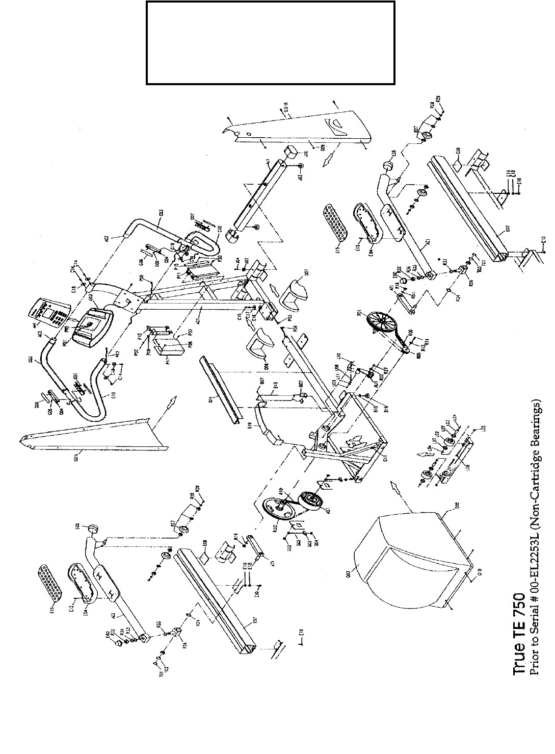
TRUE TE 750
PARTS DIAGRAM
(Non-Cartridge Bearings)
Page 28

TE 750 PRIOR TO SERIAL # 00-
EL2253L
(Non- Cartridge Bearings)
REF. # PART # DESCRIPTION QTY
AC1 7TSP0302010 PEDESTAL 1
AE1 7TSZ03307001R PEDAL ARM ASSY-RH 1
AE2 7TSZ03307001L PEDAL ARM ASSY-LH 1
AG2 7TSZEP07HDB-R HANDLEBAR ASSY-RH 1
AG3 7TSZEP07HDB-L HANDLEBAR ASSY-LH 1
AJ1 7TSZEP07FST STABILIZER ASSY-FRONT 1
AN1 7TSZM0307002 CONTROL PANEL 1
AS1 7TMZD0208007 BRAKE ASSY 1
AS1 7TMD0208016B BRAKE ASSY-AFTER SERIAL # 02-EL0541J 1
AT1 7TSZW0306007 CRANK ARM ASSY 2
AU1 7TSM0325001 BELT TENSIONER ASSY-PRIMARY 1
B07 7TME0102021 SCREW-FRAME SUPPORT 6
B15 7TMB0301002 LEVELER LOCK NUT-REAR 4
B16 7TMB0302002 LEVELER-REAR 4
B18 7TMJ1390001 COVER LOWER SUPPORT-REAR 1
B19 7TMJ1390004 COVER UPPER SUPPORT-REAR 1
C14 7TME0112029 SCREW-HANDLEBAR MOUNTING 6
C15 7TME0104165 BOLT-PEDESTAL MOUNTING 4
C16 7TME0502019 WASHER-PEDESTAL MOUNTING 4
C17 7TME0501007 SPRING WASHER-PEDESTAL MOUNTING 4
E04 7TMB0206002C PEDAL PLATE (PLASTIC) 2
E05 7TMB0609025 END CAP-PEDAL ARM 2
E07 7TSZEP25RAL PEDAL ARM TRACK 2
E08 7TMB0674006 RUBBER PAD-PEDAL ARM TRACK 2
E10 7TME0112024 SCREW-TRACK MOUNTING 8
E12 7TME0102027 SCREW-PEDAL PLATE 8
E15 7TMB0304011 PEDAL PLATE COVER (RUBBER) 2
E18 7TME0502027 FLAT WASHER-TRACK MOUNTING 8
E19 7TME0501007 SPRING WASHER-TRACK MOUNTING 8
G04 7TMB06A7001 BRACKET-PULSE SENSOR 2
G05 7TME0102069 SCREW-PULSE BRACKET 4
G06 7TMJ1278001 SENSOR PLATE-PULSE 2
G07 7TME0201028 NUT-PULSE BRACKET 4
J02 7TMB0304006 LEVELER-FRONT 2
J04 7TME0112024 SCREW-FRONT STABILIZER 2
J06 7TMB0609035 END CAP-FT STABILIZER 2
J07 7TMJ3344001 RETAINER-RAIL COVER 2
P01 7TMC0501027 CABLE-DISPLAY 1
P02 7TMC0516005 CABLE-HRC PEDESTAL END 2
P03 7TMC0535004 CABLE-BRAKE (LOWER BOARD END) 1
P05 7TMC0539003 CABLE-HRC HANDLEBAR END 2
P06 7TMC0535005 CABLE-BRAKE (BRAKE END) 1
P07 7TME0204003 NYLON NUT-REISTOR MOUNTING 4
P08 7TME0102027 SCREW-RESISTOR MOUNT 7 Page 29

P09 7TME0502082 WASHER-RESISTOR MOUNT 4
P11 7TMC0203004 CONTROL BOARD 1
P12 7TMC0736002 RESISTOR 1
P17 7TMB06B8001 MOUNT-CONTROL BOARD 1
P18 7TMJ1393003 BRACKET-RESISTOR 1
P20 7TME0107037 SCREW-RESISTOR MOUNT 11
Q01L 7TMB020202A SIDE COVER-LEFT FRONT 1
Q01R 7TMB020202R SIDE COVER-RIGHT FRONT 1
Q02 7TMB0601005 BOTTLE HOLDER 1
Q03 7TMB0222003 COVER-REAR 1
Q06 7TMB0246001 COVER-LEFT RAIL 1
Q06 7TMB0246002 COVER-RIGHT RAIL 1
Q08 7TME0102053 SCREW-REAR COVER 10
Q09 7TME0107030 SCREW-SIDE COVERS 12
Q10 7TME0107013 SCREW-REAR COVER 2
Q11 7TME0701001 C CLAMP-REAR COVER 2
Q14 7TMB0627006B COVER-CENTER FRAME MEMBER 1
R01 7TSZEP07DAX SHAFT ASSY-PEDAL CRANK 1
R02 7TSZEP07PUL SHAFT ASSY-SECONDARY DRIVE 1
R05 7TMZD0112013 POLY V WHEEL-SMALL 1
R09 7TMD0604001 POLY V BELT-PRIMARY DRIVE 1
R10 7TMD0601014 POLY V BELT-SECONDARY DRIVE 1
R16 7TME0208008 NUT-CRANK ARM 2
R21 7TME0112024 SCREW-TENSIONER MOUNTING 1
R22 7TME0502035 WASHER-TENSIONER MOUNTING 1
R26 7TSZEP17CPS PIVOT-PEDAL ARM 2
R27 7TS11317001 WHEEL-PEDAL ARM 4
R28 7TME0502026 WASHER-PEDAL ARM WHEEL 4
R29 7TME0112074 SCREW-PEDAL ARM WASHER 4
S02 7TME0202012 NUT-BRAKE AXLE NUT 2
S03 7TMJ1245001 BRACKET-BRAKE BELT ADJUSTER 2
S04 7TME0204010 NYLON NUT-BRAKE BELT ADJUSTER 2
S05 7TME0110015 BOLT-BRAKE BELT ADJUSTER 2
U08 7TME0110009 BOLT-PRIMARY BELT ADJUSTER 2
U09 7TME0102010 SCREW-PRIMARY BELT ADJUSTER 1
U10 7TME0204009 NYLON NUT-PRIMARY BELT ADJUSTER 1
U11 7TME0502098 WASHER-PRIMARY BELT ADJUSTER 1
7TMG0102032 DECAL-REAR COVER(WHITE) 2
7TME0606020 HARWARE KIT-ASSEMBLY 1
Page 30
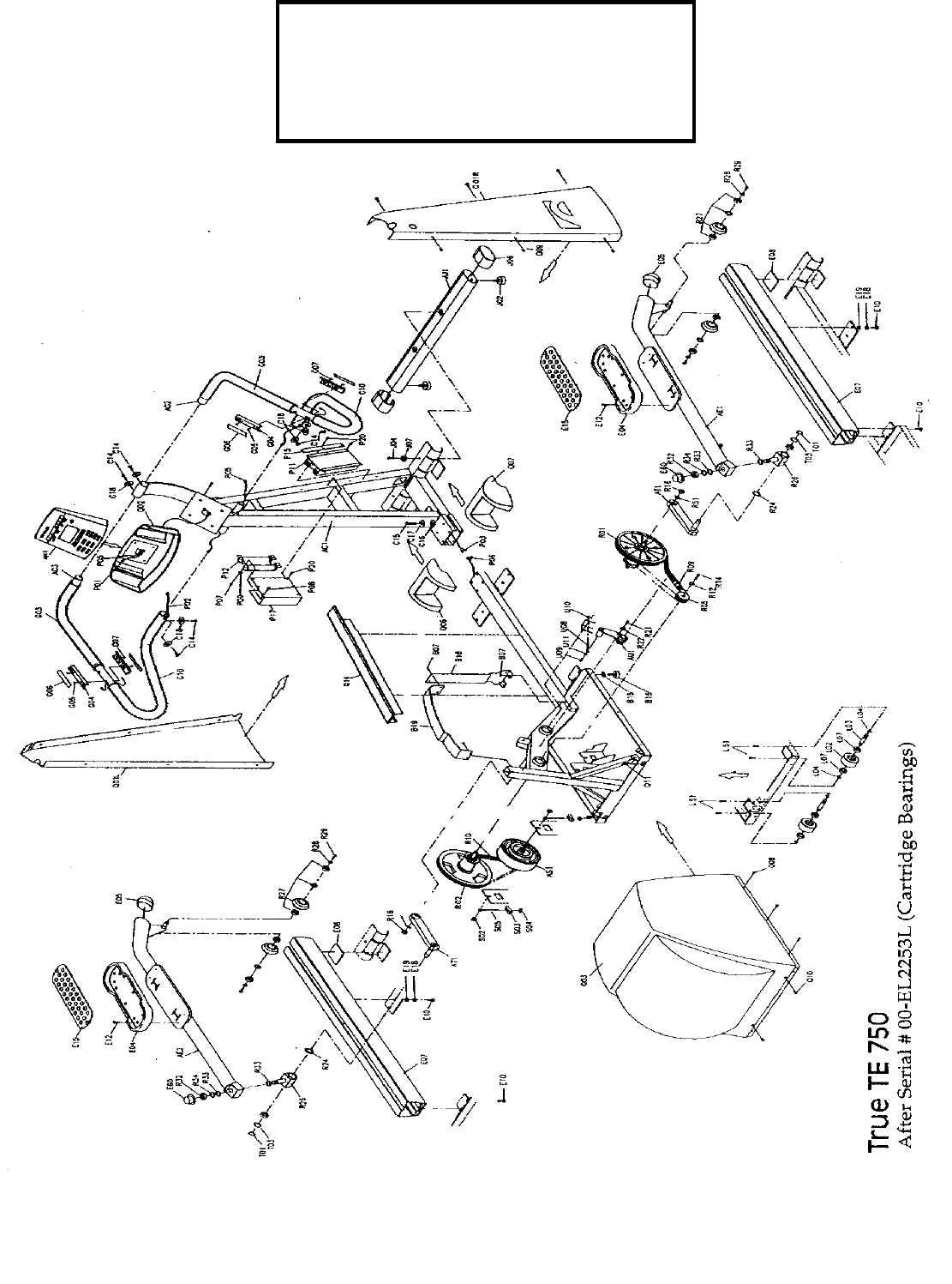
TRUE TE 750
PARTS DIAGRAM
(Cartridge Bearings)
Page 31
TE 750 AFTER SERIAL # 00-EL2253L
CARTRIDGE BEARING TYPE
REF. # PART # DESCRIPTION QTY
AC1 7TSP0302010 PEDESTAL 1
AE1 7TSZ03307001R PEDAL ARM ASSY-RH 1
AE2 7TSZ03307001L PEDAL ARM ASSY-LH 1
AG2 7TSZEP07HDB-R HANDLEBAR ASSY-RH 1
AG3 7TSZEP07HDB-L HANDLEBAR ASSY-LH 1
AJ1 7TSZEP07FST STABILIZER ASSY-FRONT 1
AN1 7TSZM0307002 CONTROL PANEL 1
AS1 7TMZD0208007 BRAKE ASSY 1
AS1 7TMD0208016B BRAKE ASSY-AFTER SERIAL # 02-EA-1102K 1
AT1 7TSZW0306007 CRANK ARM ASSY 2
AU1 7TSM0325001 BELT TENSIONER ASSY-PRIMARY 1
B07 7TME0102021 SCREW-FRAME SUPPORT 6
B15 7TMB0301002 LEVELER LOCK NUT-REAR 4
B16 7TMB0302002 LEVELER-REAR 4
B18 7TMJ1390001 COVER LOWER SUPPORT-REAR 1
B19 7TMJ1390004 COVER UPPER SUPPORT-REAR 1
C14 7TME0112029 SCREW-HANDLEBAR MOUNTING 6
C15 7TME0104165 BOLT-PEDESTAL MOUNTING 4
C16 7TME0502019 WASHER-PEDESTAL MOUNTING 4
C17 7TME0501007 SPRING WASHER-PEDESTAL MOUNTING 4
E04 7TMB0206002C PEDAL PLATE (PLASTIC) 2
E05 7TMB0609025 END CAP-PEDAL ARM 2
E07 7TSZEP25RAL PEDAL ARM TRACK 2
E08 7TMB0674006 RUBBER PAD-PEDAL ARM TRACK 2
E10 7TME0112024 SCREW-TRACK MOUNTING 8
E12 7TME0102027 SCREW-PEDAL PLATE 8
E15 7TMB0304011 PEDAL PLATE COVER (RUBBER) 2
E18 7TME0502027 FLAT WASHER-TRACK MOUNTING 8
E19 7TME0501007 SPRING WASHER-TRACK MOUNTING 8
G04 7TMB06A7001 BRACKET-PULSE SENSOR 2
G05 7TME0102069 SCREW-PULSE BRACKET 4
G06 7TMJ1278001 SENSOR PLATE-PULSE 2
G07 7TME0201028 NUT-PULSE BRACKET 4
J02 7TMB0304006 LEVELER-FRONT 2
J04 7TME0112024 SCREW-FRONT STABILIZER 2
J06 7TMB0609035 END CAP-FT STABILIZER 2
J07 7TMJ3344001 RETAINER-RAIL COVER 2
P01 7TMC0501027 CABLE-DISPLAY 1
P02 7TMC0516005 CABLE-HRC PEDESTAL END 2
P03 7TMC0535004 CABLE-BRAKE (LOWER BOARD END) 1
P05 7TMC0539003 CABLE-HRC HANDLEBAR END 2
P06 7TMC0535005 CABLE-BRAKE (BRAKE END) 1
P07 7TME0204003 NYLON NUT-REISTOR MOUNTING 4
P08 7TME0102027 SCREW-RESISTOR MOUNT 7
P09 7TME0502082 WASHER-RESISTOR MOUNT 4
P11 7TMC0203004 CONTROL BOARD 1
P12 7TMC0736002 RESISTOR 1
Page 32

P17 7TMB06B8001 MOUNT-CONTROL BOARD 1
P18 7TMJ1393003 BRACKET-RESISTOR 1
P20 7TME0107037 SCREW-RESISTOR MOUNT 11
Q01L 7TMB020202A SIDE COVER-LEFT FRONT 1
Q01R 7TMB020202R SIDE COVER-RIGHT FRONT 1
Q02 7TMB0601005 BOTTLE HOLDER 1
Q03 7TMB0222003 COVER-REAR 1
Q06 7TMB0246001 COVER-LEFT RAIL 1
Q06 7TMB0246002 COVER-RIGHT RAIL 1
Q08 7TME0102053 SCREW-REAR COVER 10
Q09 7TME0107030 SCREW-SIDE COVERS 12
Q10 7TME0107013 SCREW-REAR COVER 2
Q11 7TME0701001 C CLAMP-REAR COVER 2
Q14 7TMB0627006B COVER-CENTER FRAME MEMBER 1
R01 7TSM0330001 SHAFT ASSY-PEDAL CRANK 1
R02 7TSM0330002 SHAFT ASSY-SECONDARY DRIVE 1
R05 7TMZD0112013 POLY V WHEEL-SMALL 1
R09 7TMD0604001 POLY V BELT-PRIMARY DRIVE 1
R10 7TMD0601014 POLY V BELT-SECONDARY DRIVE 1
R16 7TME0208008 NUT-CRANK ARM 2
R21 7TME0112024 SCREW-TENSIONER MOUNTING 1
R22 7TME0502035 WASHER-TENSIONER MOUNTING 1
R26 7TSZEP17CPS PIVOT-PEDAL ARM 2
R27 7TS11317001 WHEEL-PEDAL ARM 4
R28 7TME0502026 WASHER-PEDAL ARM WHEEL 4
R29 7TME0112074 SCREW-PEDAL ARM WASHER 4
S02 7TME0202012 NUT-BRAKE AXLE NUT 2
S03 7TMJ1245001 BRACKET-BRAKE BELT ADJUSTER 2
S04 7TME0204010 NYLON NUT-BRAKE BELT ADJUSTER 2
S05 7TME0110015 BOLT-BRAKE BELT ADJUSTER 2
U08 7TME0110009 BOLT-PRIMARY BELT ADJUSTER 2
U09 7TME0102010 SCREW-PRIMARY BELT ADJUSTER 1
U10 7TME0204009 NYLON NUT-PRIMARY BELT ADJUSTER 1
U11 7TME0502098 WASHER-PRIMARY BELT ADJUSTER 1
7TMG0102032 DECAL-REAR COVER(WHITE) 2
7TME0606020 HARWARE KIT-ASSEMBLY 1
Page 33

Page 34

True Fitness
Removal &
Replacement
500R
500U
600U
600R
Page 35
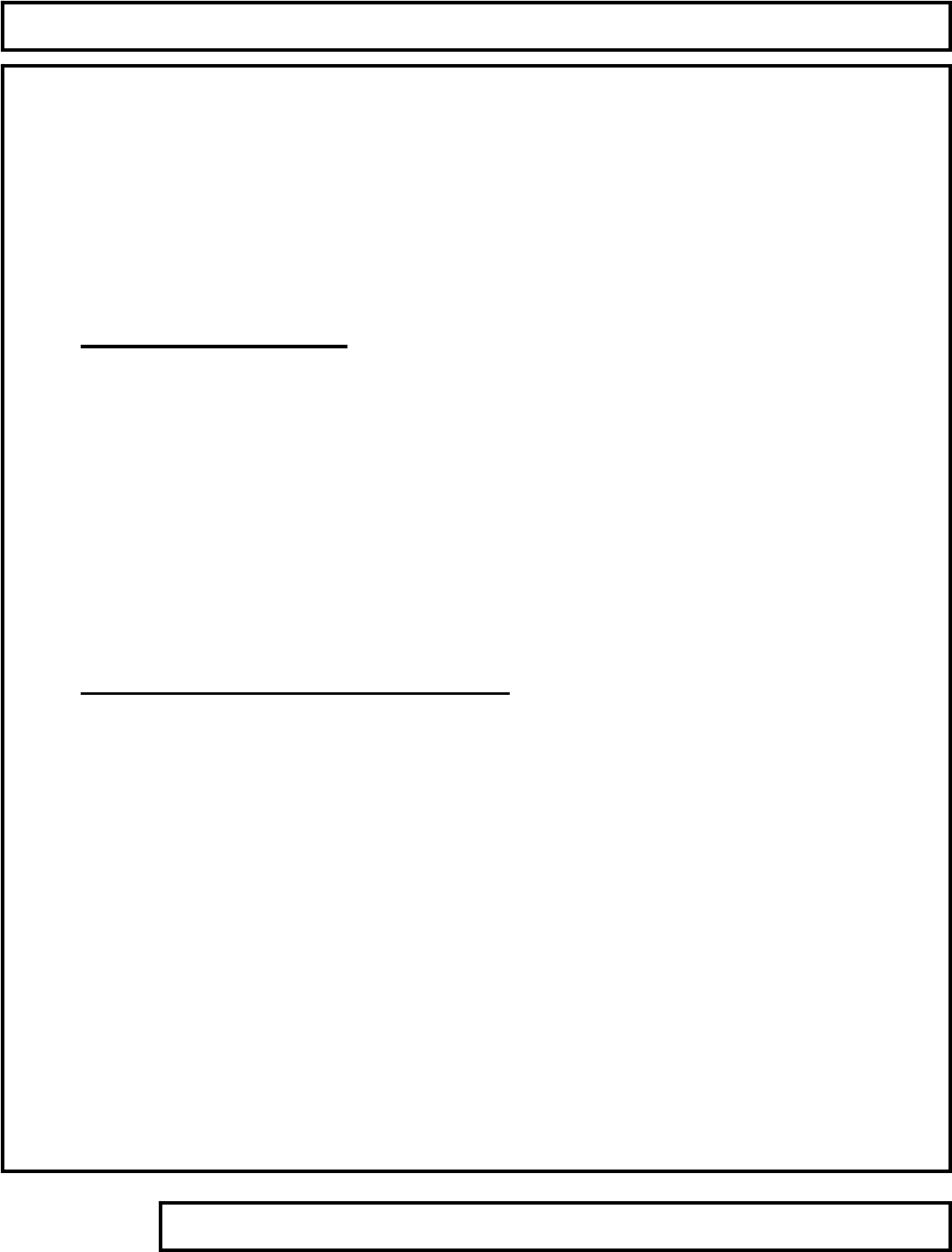
TABLE OF CONTENTS
Support Services 800-883-8783 Mon-Fri 8:30am-5:00pm Central Time Zone Fax: 636-272-7148
Removal and Replacement
600 Series Elliptical
Remove Crank Page 37
Remove Belt Wheel Page 38
Remove Brake Page 40
750E & 750EA Series Elliptical
Remove Belt & Tensioner Assembly Page 43
Remove Small Poly-V Pulley Page 44
Remove Crank & .235 Diameter Poly-V Pulley Page 46
Remove Hub Assembly Page 47
Page 36
Removal & Replacement 600
Remove Crank
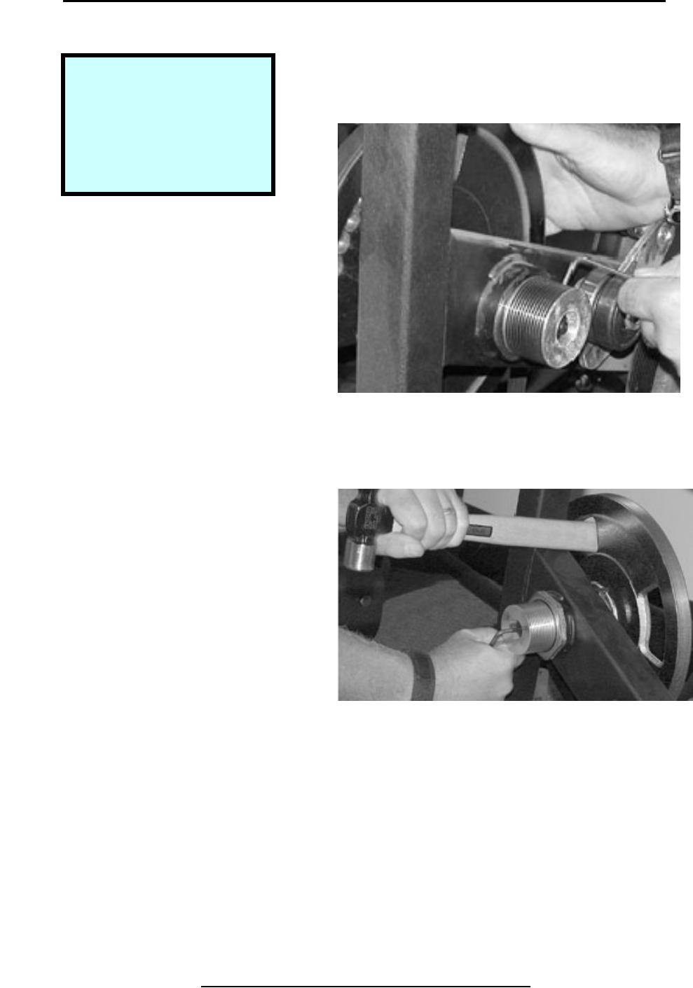
Step 1.
Place block of wood under moving
Arm assembly to prebvent counter-
clockwise rotation. Note position of
block of wood to the left of the tray.
Step 2.
Place 15mm socket end of crank
Puller over axle nut. Loosen the axle
Nut by turning the crank puller counter-
Clockwise with a crescent wrench.
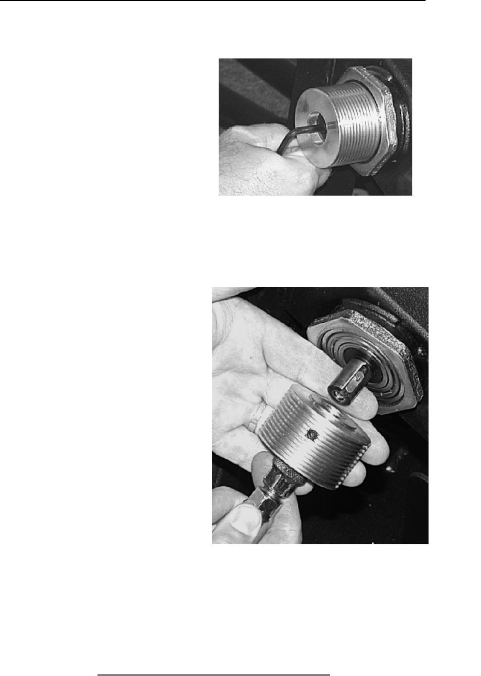
Step 3.
Remove crank assembly from hub.
Copyright 2001 True Fitness Technology, Inc. Page 37
Step 1. Wood Block Placement.
Tools Required:
Crank Puller
Crescent Wrench
Block of wood
Step 2. Axel Nut Removal.
Step 3. Remove Crank Assembly from Hub.
Removal & Replacement 600
Remove Belt Wheel
Step 1.
Loosen belt-tensioning nuts on bolts
Attached to brake axel on both sides.
Step 2.
Loosen and remove axel nuts on
Brake, both sides.
Step 3.
Push belt over edge and off of wheel.
Copyright 2001 True Fitness Technology, Inc.
Page 38
Step 2. Remove Axel Nuts.
Step 1. Loosen Belt Tensioning Nuts.
Step 3. Remove Belt from Wheel.
Tools Required:
15mm Socket nd Ratchet
11mm Box End Wrench
5mm Hex Wrench
Phillips Screw Driver
Removal & Replacement 600
Remove Belt Wheel (Continued)
Step 4.
Remove 5mm hex screws from
Bearing fixtures on both sides of belt
Wheel axel
.
Step 5.
Lift belt wheel assembly from bearing
Fixtures.
Copyright 2001 True Fitness Technology, Inc. Page 39
Step 5. Lift belt wheel assembly from bearing Fixtures.
Step 4. Remove screws from Bearing Fixtures.
Removal & Replacement 600
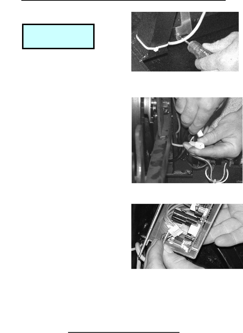
Remove Brake
Step 1.
Remove screw holding the nagnet
Brake bracket located under the rear
Brake with Phillips head screw driver.
Step 2.
Disconnect electrical terminal at
Brake.
Step 3.
Disconnect electrical terminal from
The console set at the control box
Located above the brake.
Copyright 2001 True Fitness Technology, Inc.
Page 40
Step 2. Disconnect Electrical Terminal at Brake.
Step 1. Brake Bracket Removal.
Step 3. Disconnect Cable from Control Box.
Tools Required:
Philli
p
s Screw Drive
r
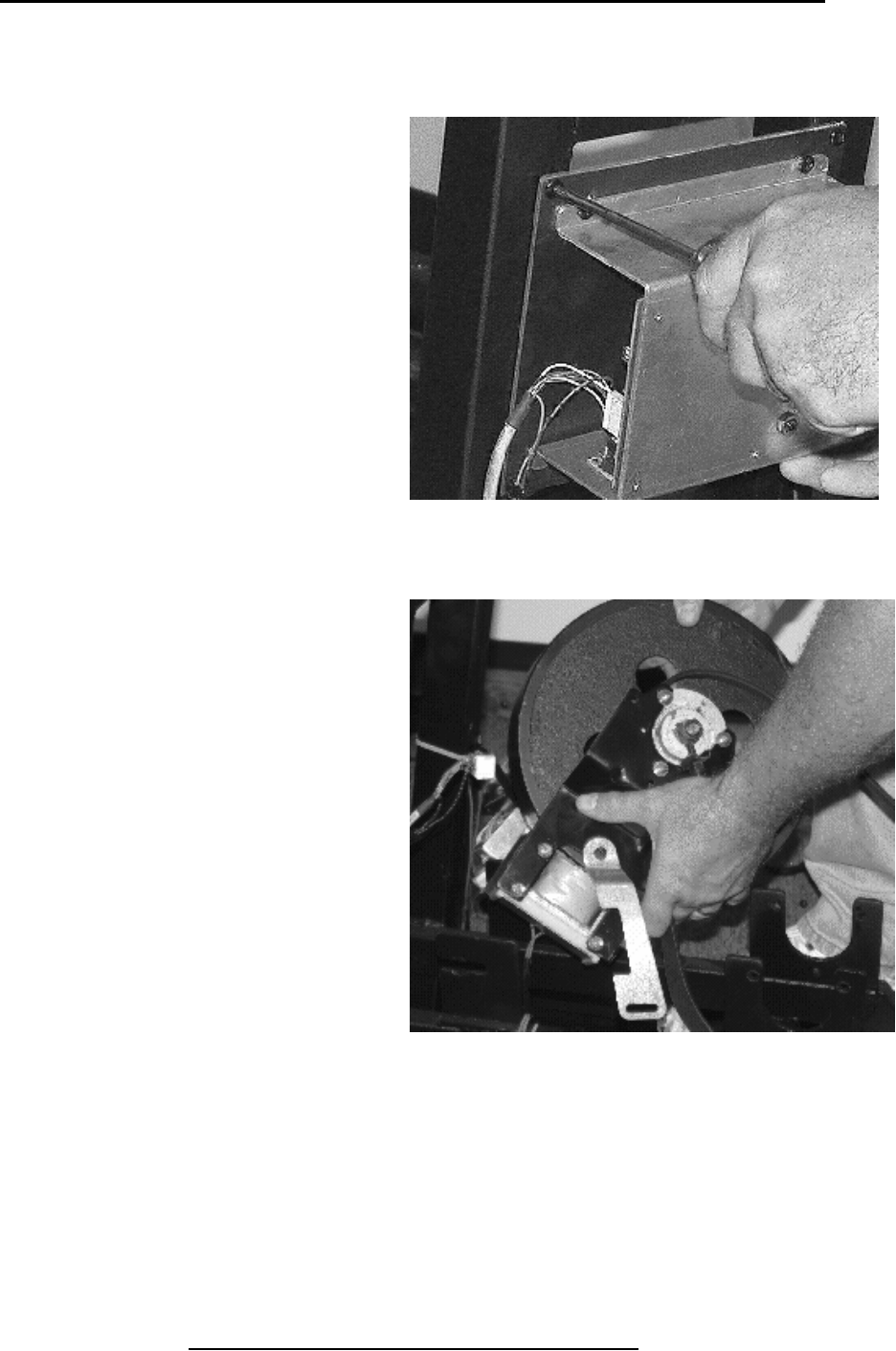
Removal & Replacement 600
Remove Brake (Continued)
Step 4.
Remove Phillips head scrwes
Holding control box above the brake
To the frame. Remove control box..
Step 5.
Pull backwards on the brake and
Magnet assembly to free it from
Slotted axle flanges. Lift brake
Out.
Copyright 2001 True Fitness Technology, Inc. Page 41
Step 5. Lift Brake & Magnet Assembly Out.
Step 4. Control Box Removal.
Removal & Replacement 600
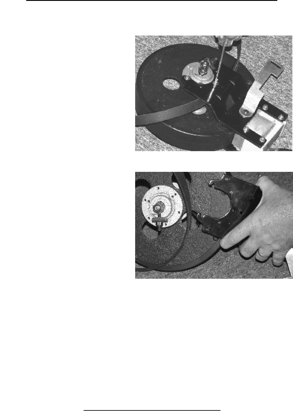
Remove Brake (Continued)
Step 6.
Remove Phillips head screws
From brackets on both sides of
Brake.
Step 7.
Remove brackets to free belt.
Copyright 2001 True Fitness Technology, Inc.
Page 42
Step 7. Remove Brake Brackets & Belt.
Step 6. Remove Screws from Bracket.
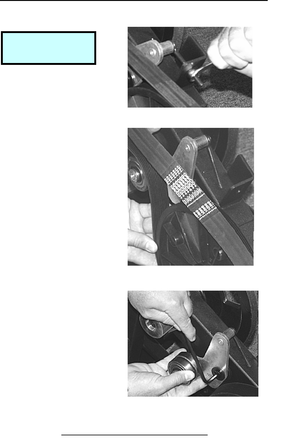
Removal & Replacement 750E & 750EA
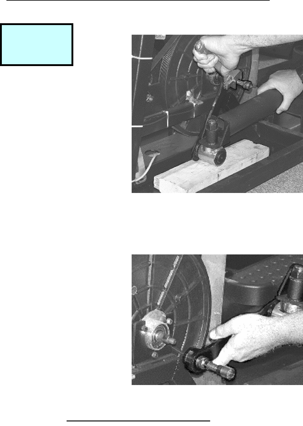
Remove Belt & Tensioner Assembly
Step 1.
Use 11mm box wrench to remove
Nut and washer from belt tensioning
screw.
Step 2.
Remove belt from belt tensioner
Assembly and wheels.
Step 3.
Use 5mm hex wrench to remove
Button head screw and washer
Attaching belt tensioner assembly to
Frame..
Copyright 2001 True Fitness Technology, Inc. Page 43
Step 2. Remove Belt.
Step 1. Remove Nut.
Step 3. Remove Tensioner.
Tools Required:
11mm Box Wrench
5mm Hex Wrench
Removal & Replacement 750E & 750EA
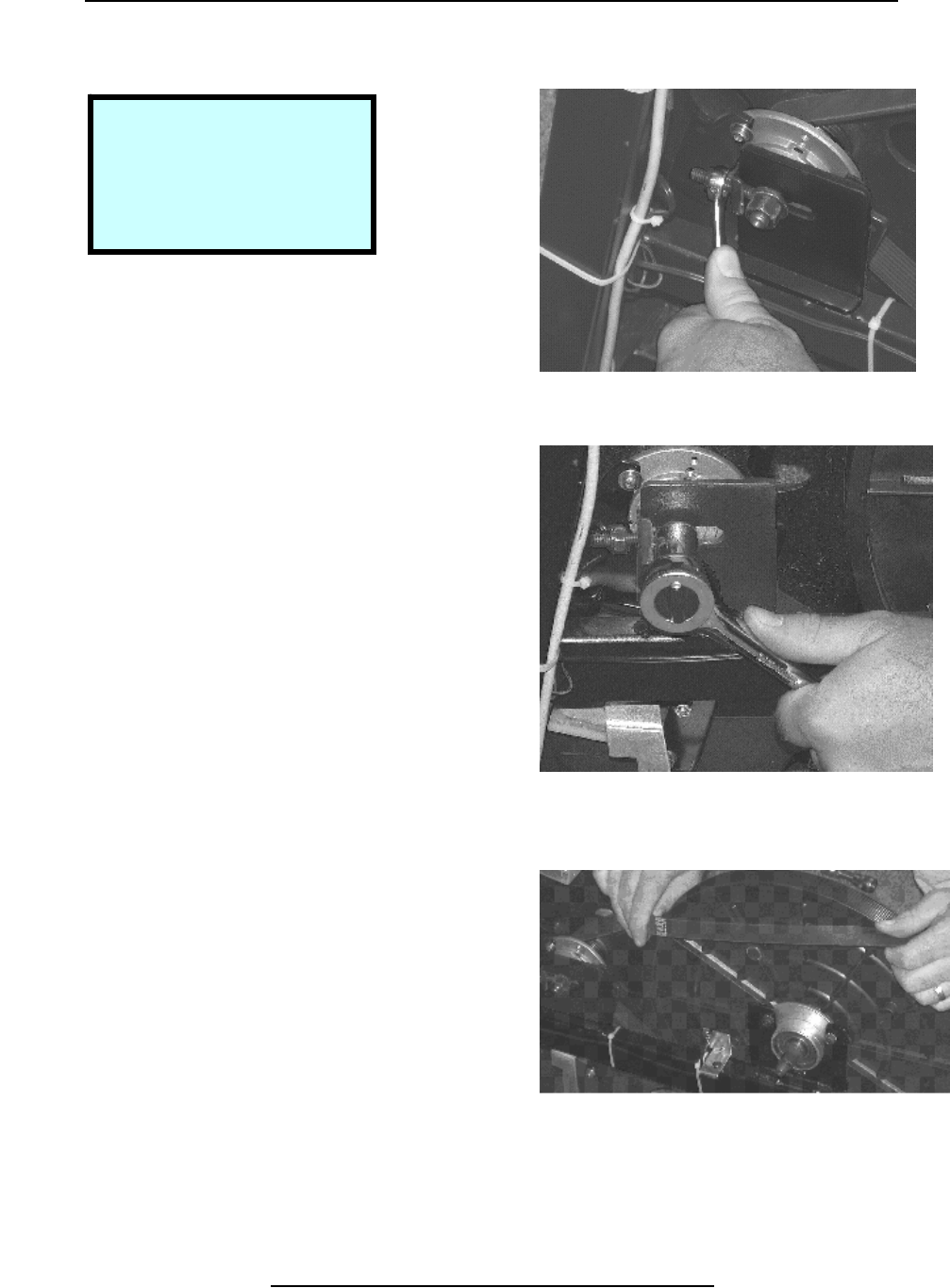
Remove Small Poly-V Pulley
Step 1.
Use 3mm hex wrench to loosen set
Screw in pulley.
Step 2.
Use Hammer Handle to prevent
Rotation of large wheel when
Removing pulley.
Copyright 2001 True Fitness Technology, Inc.
Page 44
Step 2. Prevent Rotation of Fly Wheel.
Step 1. Loosen Set Screw.
Tools Required:
3mm Hex Wrench
4mm Hex Wrench
Bicycle Crank Puller
Hammer Handle
Adjustable Wrench
Removal & Replacement 750E & 750EA
Remove Small Poly-V Pulley (Continued)
Step 3.
Use 4mm hex wrench to remove
Screw and washer holding the
Small Poly- V wheel on.
Step 4.
Remove Poly-V wheel using bicycle
Crank puller and adjustable wrench
Remove key from shaft.
Copyright 2001 True Fitness Technology, Inc. Page 45
Step 4. Use Puller to Remove.
Step 3. Remove Center Screw.
Removal & Replacement 750E & 750EA
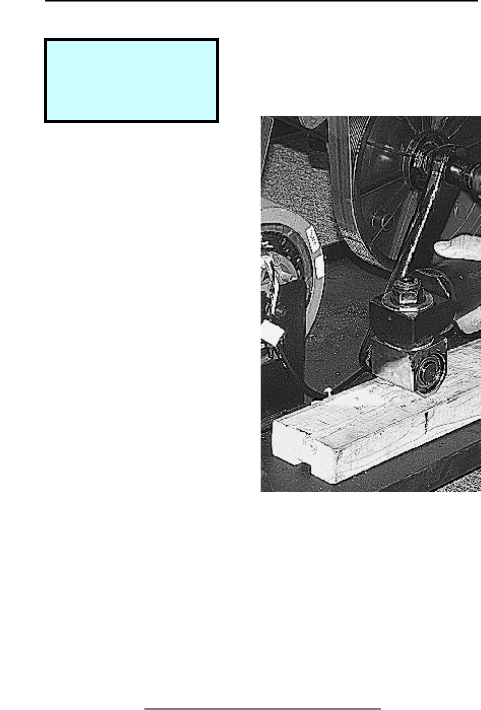
Remove Crank & .235 Diameter Poly-V Pulley
Step 1.
Place block of wood under crank at
Left to prevent counter-clockwise
Rotation.
Step 2.
Remove center nut using 21mm
socket & ratchet.
Copyright 2001 True Fitness Technology, Inc.
Page 46
Step 2. Prevent Rotation of Fly Wheel.
Step 1. Block to Prevent Rotation.
Tools Required:
Block of Wood to Block Crank
21mm Socket & Ratchet
Metric Cotter-less Crank Puller
10mm Hex Wrench
Removal & Replacement 750E & 750EA
Remove Crank & .235 Diameter Poly-V Pulley (Continued)
Step 3.
Move block of wood to right of
Crank to prevent clockwise rotation.
Step 4.
Place metric cotter-less crank puller
Over end of crank shaft.
Turn puller clock-wise with 10mm
Hex wrench to remove crank.
Step 5.
Pull crank arm off of crank shaft
And set moving arm aside.
Copyright 2001 True Fitness Technology, Inc. Page 47
Step 4. Pull Crank.
Step 3. Block to Prevent Rotation.
Step 5. Move Arm Aside.
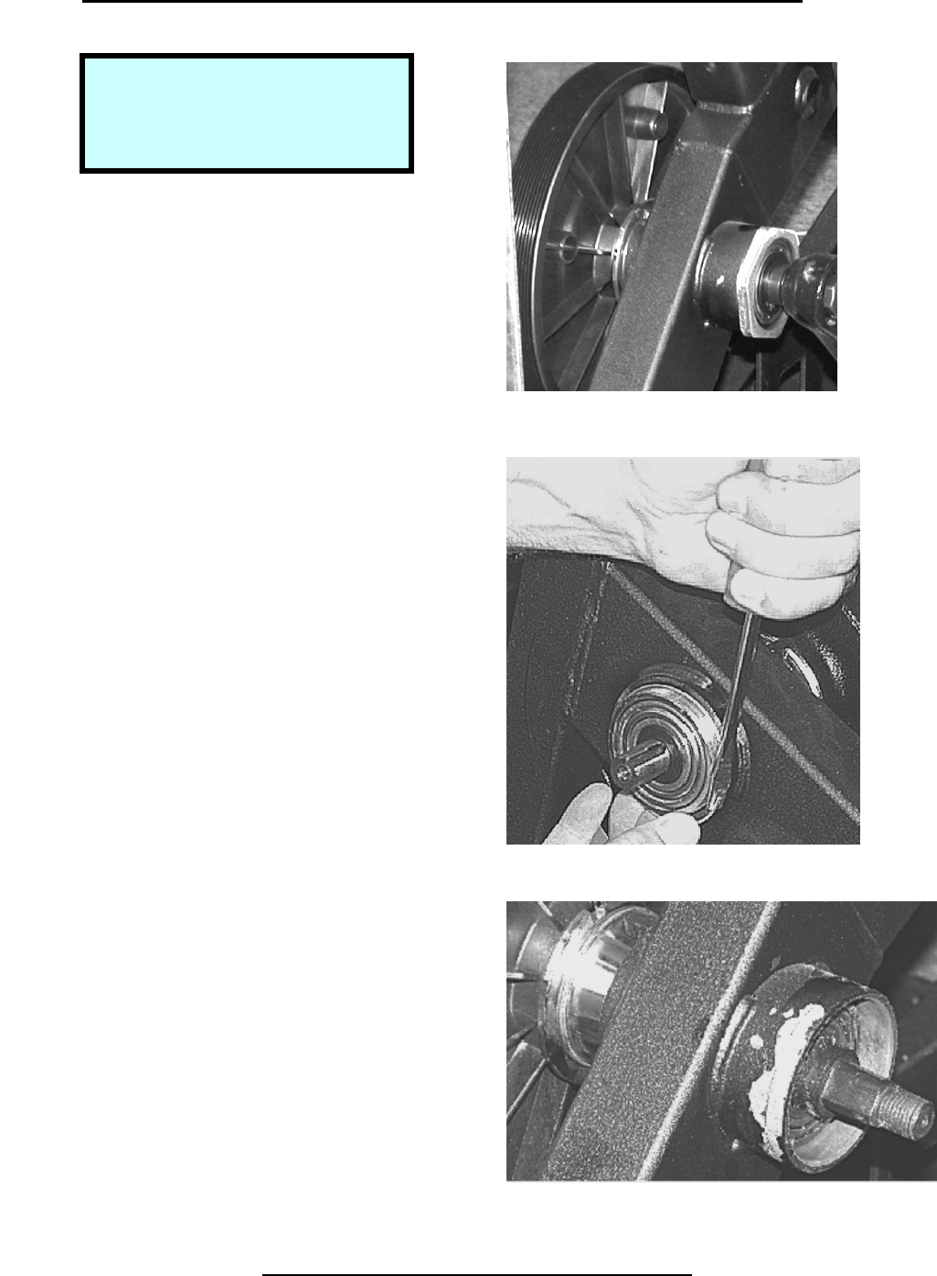
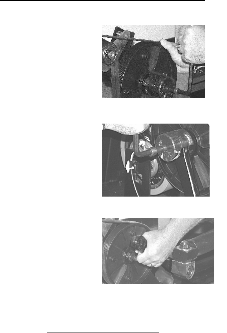
emoval & Replacement 750E & 750EA
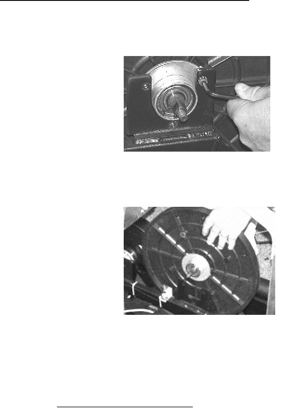
Remove Hub Assemblies
Step 1.
Use elliptical wrench or pliers to
Remove large hex nuts holding hub
Assembly in place.
Step 2.
Remove retainer clip with flat-blade
Screwdriver
To remove wheel from frame, slip
Shaft through bearing.
Step 3.
Pull wheel and hub assembly out as
A unit. Bearings and axle cannot be
Field serviced.
Copyright 2001 True Fitness Technology, Inc.
Page 48
Step 2. Remove Clip.
Step 1. Remove Large Hex Nut.
Step 3. Pull Assembly Out.
Tools Required:
Elliptical Wrench (pn: 90361501)
Channel Lock Pliers
Flat Blade Screwdrive
r
