Tung Keng Enterprise LK001 Console for Sporting Goods User Manual
Tung Keng Enterprise Co. Ltd Console for Sporting Goods
User Manual
25
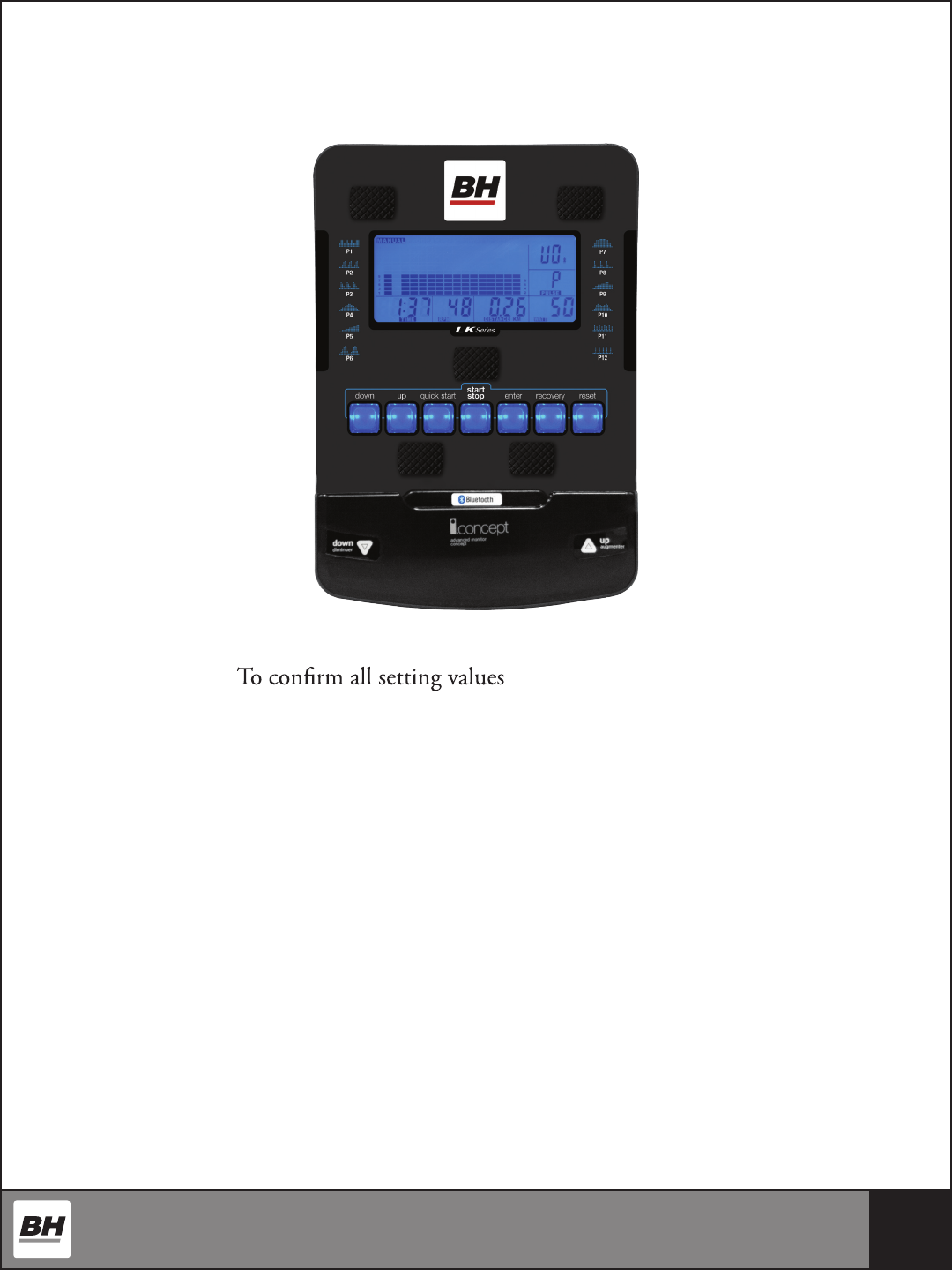
LK500Ui / Ri / Ei CONSOLE OPERATIONS
SPECIFICATIONS:
ENTER
RESET To reset all parameters to default value
START/STOP To start or stop training
UP To make upward setting change
DOWN To make downward setting change
RECOVERY In stop or start mode, pressing this button will start Heart Rate
recovery status measurement. Time will count down from 60 seconds
QUICK START Starts the machine without any preset program or data from user
FUNCTION:
TIME Displaying the workout time while exercising
SPEED Displaying the current speed
DISTANCE Accumulating the distance while exercising
PULSE 30-240 BPM
CALORIES Counts calories while exercising
RPM Displaying crank speed in revolution per minute
26
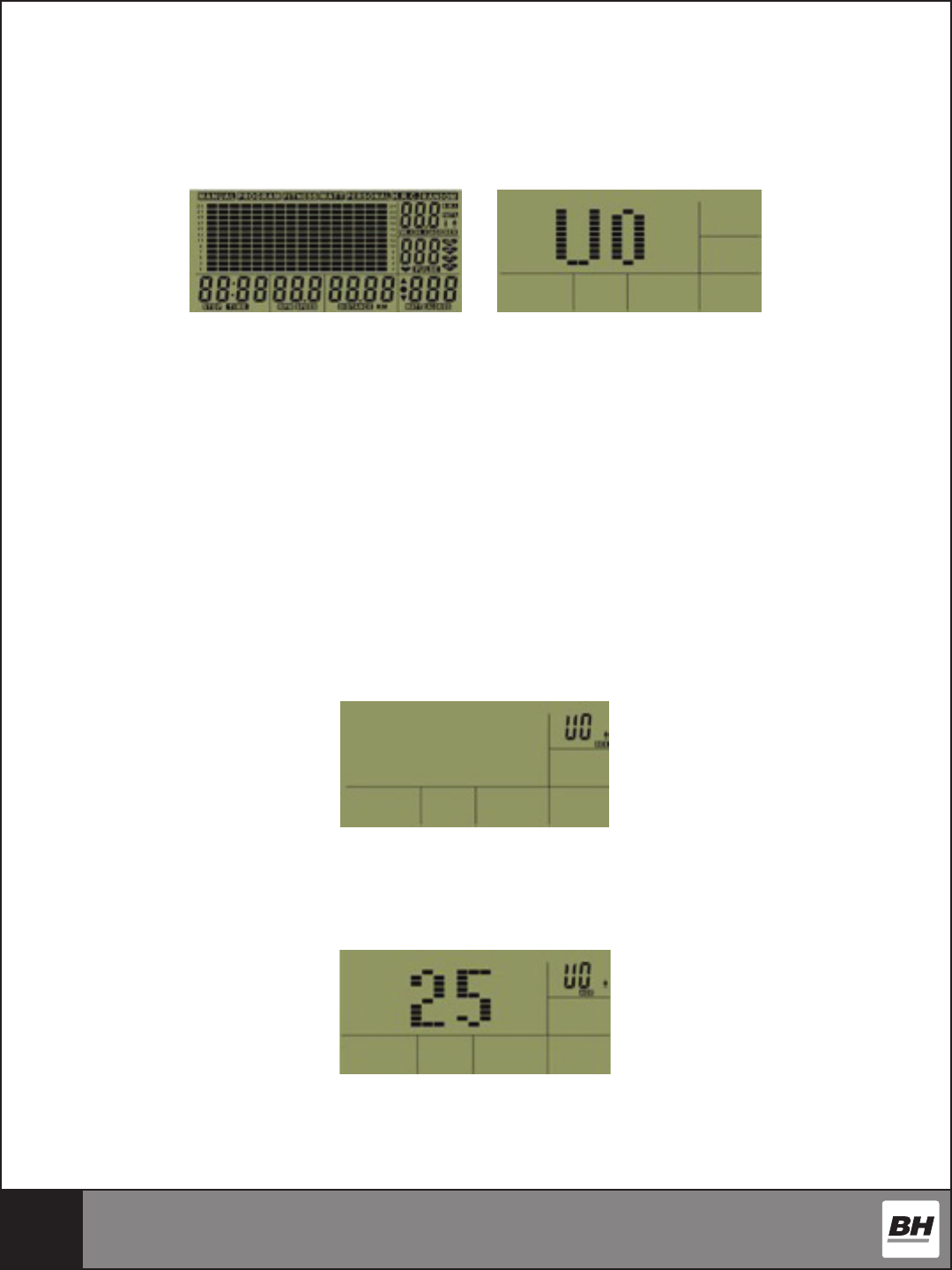
POWER MODE
When the machine powers on, the display will light up with all numerals. After two seconds,
it will enter the "user selecting" mode. If the user does not operate the machine, or the
machine receives no signal after 4 minutes, the computer will enter an idol mode.
GETTING STARTED - OPERATING PROCEDURE:
Start pedaling and the console will turn on. Use the UP/DOWN buttons to set up your
user data by selecting any user U0-U4. Press the ENTER button to accept user selection.
Press UP/DOWN buttons to toggle between genders. Press ENTER to accept. Use the UP/
DOWN to set AGE then press ENTER. Use the UP/DOWN buttons to enter height in
inches then presss ENTER to accept. Use the UP/DOWN buttons to input weight then
press ENTER to select. See below for step by step instructions.
1. Press ENTER to conrm the USER, then enter the sex setting. e right side will
displays SEX, use the UP/DOWN buttons to choose male or female.
2. Press ENTER to conrm the gender selection, then enter the AGE setting. e right side
will display AGE, use the UP/DOWN buttons to select age setting.
27
3. Press ENTER to conrm the AGE setting, then enter the HEIGHT setting. e right
side will display HEIGHT, use the UP/DOWN buttons to select the HEIGHT setting.
4. Press ENTER to conrm the WEIGHT setting, then enter WEIGHT setting. e right
side will display WEIGHT, use the UP/DOWN buttons to select the WEIGHT value.
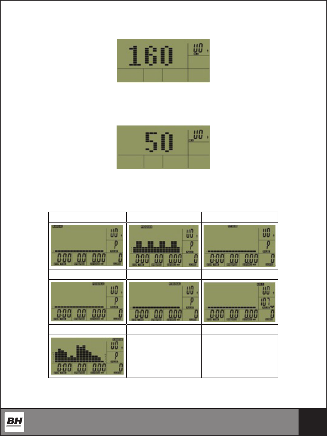
5. Press ENTER to conrm the HEIGHT setting, then enter the exercise program selecting
page. Use the UP/DOWN buttons to select between the exercise programs below.
MANUAL PROGRAM FITNESS
WATT PERSONAL HRC
RANDOM

28
NAVIGATING THE PROGRAMS
MANUAL MODE
User may preset their own resistance level from 1 to 24 by pressing the UP/DOWN buttons.
e default resistance level is 1. Press ENTER to conrm. Using the UP/DOWN buttons
enter values for TIME, DISTANCE, CALORIES, PULSE, and then press START to begin
your workout.
PROGRAM MODE
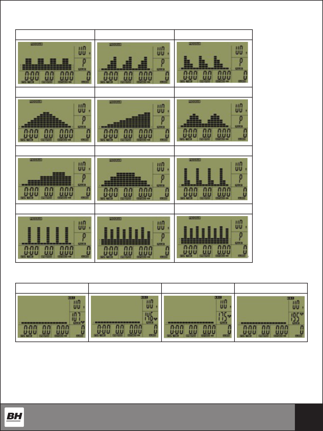
ere are 12 preset programs. Use the UP/DOWN buttons to select the desired program
prole, then press the ENTER button to conrm. Use the UP/DOWN buttons to adjust
the resistance level. Press ENTER to conrm. Enter values for TIME, DISTANCE,
CALORIES, PULSE, and then press START/STOP to begin your workout.
FITNESS TEST
Use the UP/DOWN buttons to select FITNESS and press ENTER. Press START/STOP to
start the test. e user has to achieve the greatest distance possible in 8 minutes. When the
time is up, the electronic device will work out the dierence and your tness rating will be
displayed up on the screen.
PERSONAL MODE
Users may create their own prole in this mode. e rst segment of the prole will start
blinking. Use the UP/DOWN buttons to adjust resistance level for each segment. Once all
16 segments have been entered, press the ENTER button to conrm. Press START/STOP
to begin your workout.
WATT CONTROL MODE
Enter values for TIME, DISTANCE, CALORIES, PULSE, and then press START/STOP
to begin your workout. User may set the Watt value by pressing the UP/DOWN buttons to
change in 10 Watt increments.
HRC MODE
Input personal data: SEX, AGE, HEIGHT and WEIGHT.
User may select dierent target Heart Rate from 55%, 75%, 90% and TARGET by using the
UP/DOWN buttons. Press ENTER to conrm. en, enter values for TIME, DISTANCE,
CALORIES, and then press START/STOP to begin your workout.
29
PRESET PROGRAMS
P2 P2 P3
P4 P5 P6
P7 P8 P9
P10 P11 P12
HRC PROGRAMS (55%, 75%, 90%, TAG)
HRC 55% HRC 75% HRC 90% HRC Target Heart Rate
30
TEST FUNCTIONS
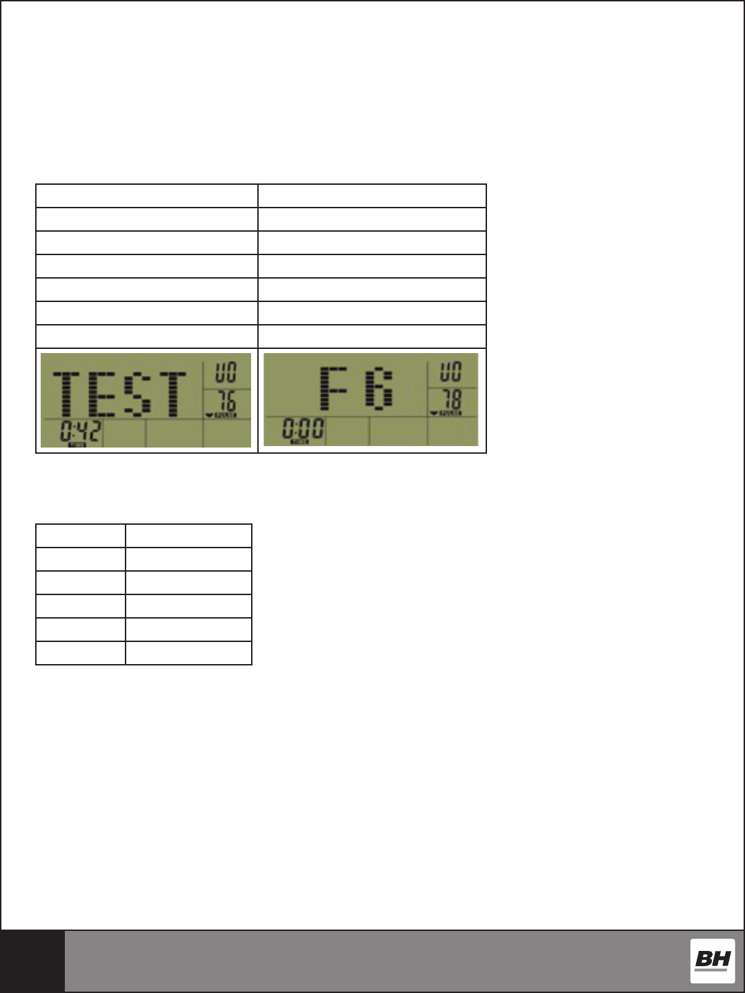
RECOVERY TEST
Press RECOVERY key to test HRC recovery speed. When in test mode, it will detect the
HRC within 10 seconds. When nished, if there is no HRC displayed, the program will exit
out of the HRC recovery mode. If there is HRC displayed, the workout will enter into 60
seconds HRC recovery. Test result is shown below:
VALUE CONDITION
F1 Best
F2 Very good
F3 Good
F4 Normal
F5 Bad
F6 Worse
FITNESS TEST
Enter FITNESS program and start the test. Test time is 8 minutes. Test result is below:
VALUE CONDITION
F1 Very Good
F2 Good
F3 Fair
F4 Poor
F5 Very Poor
31
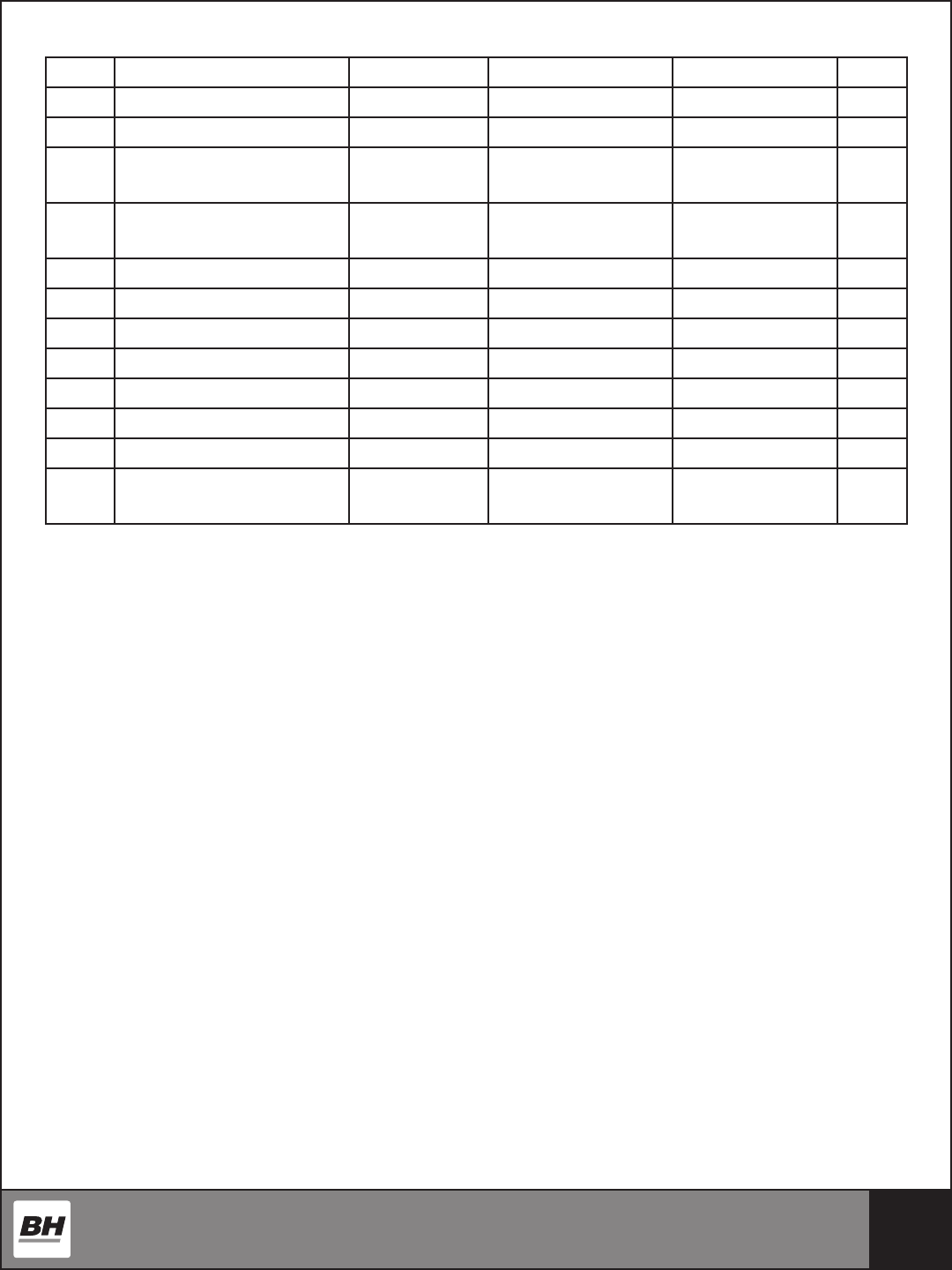
FUNCTION STATISTICS AND RANGES
ITEM SCREEN SHOWN RANGE SETTING RANGE PRESET VALUE SAVE
1 SEX MALE/ FEM yes
2 AGE 10 - 100 yes
3 WEIGHT(METRIC) 20 - 330(Lb)
10 - 150 (KG)
yes
4 HEIGHT 36 - 84(INCH)
90 – 21 0(CM)
yes
5 TIME 0:00 - 99:59 0:00 - 99:00 0:00 no
6 DISTANCE 0.0 - 99.99 0.0 - 99.50 0.0 no
7 CALORIES 0 - 999 0 - 990 0 no
8 SPEED 0.0 - 99.9 0.0 no
9 PULSE 30 - 200 bpm 0 no
10 WATT 0 - 999 0 no
11 RPM 0 - 250 rpm 0 no
12 BRAKE RESISTANCE
LEVEL
L1 - L24 L1 no
“WARNING! Heart rate monitoring systems may be inaccurate. Over exercising may result
in serious injury or death. If you feel faint stop exercising immediately.

32
DOWNLOADING APPS AND
PAIRING YOUR DEVICE WITH YOUR EQUIPMENT
DOWNLOADING THE SOFTWARE
Connect the Apple device with the App Store (iTunes) or your Android Device with Google
Play, search for "Pafers", then read the APP introductions and Download the APPs with
bicycle/elliptical machine functions to your device, for example Pedal Monitor or other
applicable apps. Note: if you download an APP for a treadmill and pair it with an Elliptical it
will not work.
• e App uses bluetooth mode, so please make sure the equipment and the device you are
using both have bluetooth function.
• e App contains the following functions, the user must open the 3G network or wi-
network:
(a) Managing Data - After completing the registration in the "Pafers" App, log on to your
personal account. Now that you have registered you can record all of your workout data and
save it to your device.
(b) Some APPs need connection to Google maps in order to function correctly.
PAIRING THE BLUETOOTH DEVICE WITH AN APPLE DEVICE
1. Place the Apple Device on the area in front of the LCD screen.
2. Enter into settings and turn Bluetooth on.
3. Your Apple Device will detect all Bluetooth devices within range (following on screen
instructions), click on the appropriate bluetooth device name and conrm your
connection.
4. After paired successfully, please start the APP within 2 minutes, if you do not, Bluetooth
will automatically cancel the pairing. Please keep the Apple Device within a range of 2
meters for best quality connection. If you see “not connected,” please perform the above
steps again.
5. Press the Apple Device home button, the screen will return to the desktop.
6. Start the APP you downloaded. When the APP connects with the equipment successfully,
the APP screen buttons will unlocked. Start from APP interface using a variety of modes
to control the exercise equipment. Pay attention to the APP instructions and function
introduction. If you have need help with the APP, please browse the APPs download
page description or contact Pafers for instructions.
7. When you are done using the APP, please press the HOME button on the Apple Device
twice to close the APP.

33
PAIRING THE BLUETOOTH DEVICE WITH AN ANDROID DEVICE
1. Place the Android Device on the area in front of the LCD screen.
2. Enter into settings and turn Bluetooth on.
3. Your Android Device will detect all Bluetooth devices within range (following on
screen instructions), click on the appropriate bluetooth device name and conrm your
connection.
4. After paired successfully, please start the APP within 2 minutes, if you do not, Bluetooth
will automatically cancel the pairing. Please keep the Android Device within a range of 2
meters for best quality connection. If you see “not connected,” please perform the above
steps again.
5. Press the Apple Device home button, the screen will return to the desktop.
6. Start the APP you downloaded. When the APP connects with the equipment successfully,
the APP screen buttons will unlocked. Start from APP interface using a variety of modes
to control the exercise equipment. Pay attention to the APP instructions and function
introduction. If you have need help with the APP, please browse the APPs download
page description or contact Pafers for instructions.
7. When you are done using the APP, please press main screen button on the Android
Device twice to close the APP.
COMPATIBLE DEVICES
Android
Bluetooth & App Enabled Android Device
Apple Products
iPod touch (4th generation) iPod touch (3rd generation)
iPhone 5 iPhone 4S
iPhone 4 Mini iPad
iPad iPad 2
i.Concept Bluetooth products are compatible with Apple devices with iOS 5.1 or later. It is
recommended to update iOS to latest version to obtain the best user experience.
iPad, iPhone, iPod, iPod classic, iPod nano, iPod shue, and iPod touch, is a registered
trademark of Apple, Inc., in the United States and other countries.
“Made for iPod,” “Made for iPhone,” and “Made for iPad” mean that an electronic accessory
has been designed to connect specically to iPod, iPhone, or iPad, respectively, and has been
34
for the operation of this device or its compliance with safety and regulatory standards.
trademarks of Apple Inc., registered in the U.S. and other countries.
Care has been taken to assure that your equipment has been properly adjusted and
lubricated at the factory. It is not recommended that the user attempt service on the internal
components. Instead, seek service from an authorized service center. However, you may
clean the outer surface. Use a soft cloth, dampened with warm water. Do not use aerosol
of harsh chemicals will destroy the protective coating and cause a static build-up that may
damage the some of the components.
MAINTENANCE AND CLEANING
FCC ID: PHGLK001
NOTE
This equipment has been tested and found to comply with the limits for a Class B
digital device, pursuant to Part 15 of the FCC Rules. These limits are designed to
provide reasonable protection against harmful interference in a residential installation.
This equipment generates, uses and can radiate radio frequency energy and, if not
installed and used in accordance with the instructions, may cause harmful interference
to radio communications.
However, there is no guarantee that interference will not occur in a particular
installation. If this equipment does cause harmful interference to radio or television
reception, which can be determined by turning the equipment off and on, the user is
encouraged to try to correct the interference by one or more of the following
measures:
◆ Reorient or relocate the receiving antenna.
◆ Increase the separation between the equipment and receiver.
◆ Connect the equipment into an outlet on a circuit different from that to
which the receiver is needed.
◆ Consult the dealer or an experienced radio/TV technician for help.
Warning: Changes or modifications to this unit not expressly approved by the party
responsible for compliance could void the user authority to operate the equipment.
1. To comply with FCC RF exposure compliance requirements, a separation distanc
of at least 20 cm must be maintained between the antenna of this device and all
persons.
2. This Transmitter must not be co-located or operating in conjunction with any other
antenna or transmitter.
35
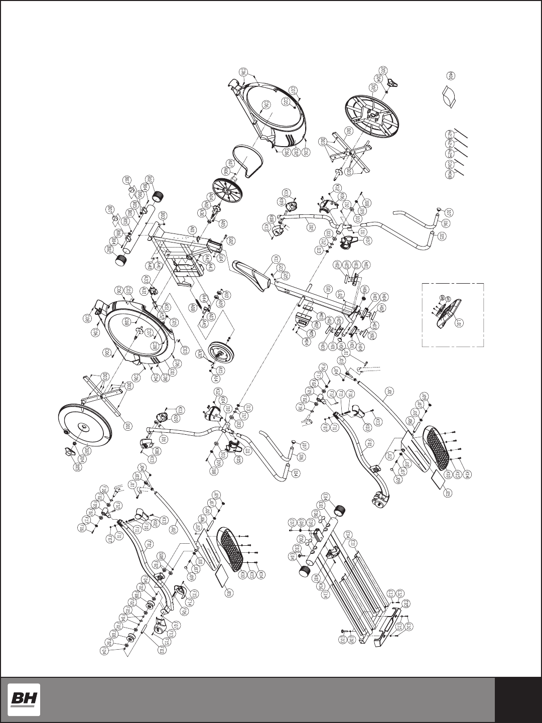
EXPLODED VIEW DRAWING
36
PARTS LIST
To order replacement parts: provide your customer service representative with the product model
number and the part number located on the Parts List below, along with the quantity you require.
No. Description Qty No. Description Qty No. Description Qty
(A) FRAME AND FITTINGS 1 (E) REAR STABILIZER SET 1 I03 Bearing 4
A01 Frame assembly 1 E01 Rear stabilizer set assembly 1 I04 Handlebar tube upper assembly L 1
A02 Crank assembly 1 E02 Hex screw nut m8xp1.25 2 I05 Handlebar tube upper assembly R 1
A03 Idle wheel assembly 1 E03 Adjustment foot pad 4 I06 HDR foam grip φ31x3.0Tx970 2
A04 Belt wheel φ310 1 E04 End cap φ75 2 I07 End cap -φ1-1/4” 2
A05 Hex screw m8xp1.25X15 4 E05 Rear stabilizer cover 1 I08 Hex screw m8xp1.25X15 2
A06 Nut m8xp1.25 4 E06 End cap φ1-1/2”x2.0T 4 I09 Flat washer φ8.5Xφ30x2.0T 2
A07 Drive belt 480” 1 E07 CKS hex screw m10xp1.5X40 3 I10 Screw m8xp1.25X45 4
A08 Spring A 1 E08 Spring washer m10 3 I11 Nut m8xp1.25 4
A09 Bearing 2 E09 Flat washer φ10xφ20x1.5T 3 I12 Wave washer ∮26.4X∮34.2X0.3T 4
A10 C-shaped ring φ15 1 E10 Cross screw m4xp0.7X15 2 I13 Washer φ25xφ35x1.0T 2
A13 Flywheel φ260 1E11 Wheel compressing board 2
A14 Screw nut 3/8”-26 thread 2 E12 Hex screw m8xp1.25X15 4 (J) RELATED POLE SET 1
A15 Hex screw nut 3/8”-26 thread x4t 2 E13 Nut m8 4 J01 Pole set assembly R 1
A23 Belt 4.8X330mm 7 E14 Foam sticker 600mmx25mmx1.5T 4 J02 Pole set assembly L 1
A24 Belt 2.2X80mm 1 E15 Washer φ4xφ10x1.0T 2 J03 Shaft -pos12-r (φ12 right thread) 2
A25 Belt 3.6X102mm 1 J04 Nut m12xp1.75 4
A27 Sensor xing base 1 (F) FOOT PEDAL AND FITTINGS 1 J05 Foam sticker 90x90x3.0T 2
A28 Cross screw m4xp0.7X10 1 F01 Foot pedal iron tube assembly 2 J06 Shaft 2
A29 Power supply 1 F02 Bearing 16 J07 CKS hex screw m8xp1.25X15 4
A30 Crank shaft bushing 1 F03 Wheel xing bushing 2 J08 Plastic washer 2
A31 Small motor (wire puller) 1 F04 Inner and outer shaft tube (short) 8 J09 End cap 4
A32 Steel rope 1 F05 Wave washer φ17xφ24x0.3T 2 J10 Washer φ8.5Xφ19x2.0T 4
A33 Screw m5xp0.8X12 4 F06 Fixing screw m8xp1.25X135 2 J11 CKS hex screw m12xp1.75X40 2
A40 Wire clip xing knob uc-2 3 F07 Nut m8xp1.25 4 J12 CKS hex screw m6xp1.0X10 2
A41 Cross screw m4xp0.7X10 3 F08 PU wheel φ74x44 4
A42 Hex screw m8xp1.25X25 1 F09 Foot pedal xing plate assembly (front) 2 (K) PLASTIC FITTINGS 1
A43 Washer φ8xφ16x1.5T 1 F10 CKS hex screw m8xp1.25X85 2 K01 Frame cover middle 1
A44 Washer φ8xφ19x3.0T 1F11 Arc washer 4 K02 Foot pedal iron tube cover L 1
A45 Nut m8xp1.25 1 F12 Foot pedal iron tube plastic iron core 2 K03 Foot pedal iron tube cover R 1
A51 Steel rope xing plate 1 F13 Wheel cover L 2 K04 Handlebar tube cover front L 1
A52 Screw m5xp0.8X10 1 F14 Wheel cover R 2 K05 Handlebar tube cover rear L 1
F15 Cross screw m4xp0.7X15 4 K06 Handlebar tube cover front R 1
(B) FRONT BASE TUBE SET 1 F16 Hex screw m8xp1.25X15 2 K07 Handlebar tube cover rear R 1
B01 Front base tube assembly 1 F17 Washer φ8xφ25x2.0T 2 K08 Connecting pole cover L 2
B02 End cap ø75 2 F18 Wave washer φ17xφ24x0.3T 2 K09 Connecting pole cover R 2
B03 Hex screw nut 2 K10 Foot pedal 2
B04 Hex screw m8xp1.25X45 2 (G) CONTROL TUBE SET 1K11 Control tube plastic 1
B05 Nut m8xp1.25 2 G01 Control tube assembly 1 K12 Self-tapping screw φ5x15 8
B06 Washer φ8xφ16x2.0T 2 G02 CKS hex screw m10xp1.5X70 2 K13 Screw m4xp0.7X15 6
B07 Bearing wheel φ70xφ8x28t 2 G03 CKS hex screw m8xp1.25X15 1 K14 Screw m5xp0.8X10 8
G04 Nut m10xp1.25 2 K15 Washer φ6xφ13x1.0T 8
(C) OUTER COVER SET 1 G05 Washer φ8xφ25x2.0T 1 K16 Screw m5xp0.8X10 1
C01 Frame side cover L 1 G06 Guide thread l=300 2
C02 Frame side cover R 1 G07 Computer xing plate D 1 (L) COMPUTER CONSOLE AND WIRES 1
C03 Plastic locked xing iron plate 2 G08 Screw m5xp0.8X12 4 L01 Console 1
C04 Plastic locked xing iron plate-short 1 L02 Screw m4xp0.7X10 4
C05 Washer φ6xφ16x1.0T 2 (H) HAND GRIP PULSE SET 1 L06 Lower control wire 1
C06 Screw m5xp0.8X10 10 H01 Hand grip pulse plastic base 4 L09 Speed sensor wire 1
C07 Screw m5xp0.8X12 2 H02 Hand grip pulse sensor plate 4 L10 Power supplier wire 1
C08 Self-tapping screw φ5x12 4 H03 Double side tape 25mmx75mmx0.3T 4
H04 Screw m3xp0.5X30 4 (M) OTHER 1
(D) TURNPLATE SHELF AND FITTINGS 1 H05 Hex screw nut m3xp0.5 4 M01 Parts bag 1
D01 Turnplate cross shelf assembly 2 H06 End cap -φ1-1/4” 2 M02 Waterbottle holder 1
D02 Plastic turnplate 2 M03 Waterbottle holder bracket 1
D03 Self-tapping screw φ5x15 16 (I) HANDLE BAR SET 1 M04 Screw m6xp1.0X15 2
D04 Screw nut (washer) m14xp1.5X10t 2 I01 Handlebar tube assembly L 1 M05 Washer ψ6xψ13x1.0T 2
D05 Turnplate cover 2 I02 Handlebar tube assembly R 1 M08 Guide thread l-300 black 4
φ=Diameter

37
LIMITED LIGHT COMMERCIAL WARRANTY
BH North America will repair or replace, free of charge, at its option, parts that are
defective as a result of material or workmanship. Seven (7) year replacement warranty
coverage on frame and ve (5) years on other parts. Labor warranty coverage is one (1)
year. Warranty covers the original consumer purchaser only.
LIMITED RESIDENTIAL WARRANTY
BH North America will repair or replace, free of charge, at its option, parts that are
defective as a result of material or workmanship. Lifetime replacement warranty coverage
on frame and ten (10) years on other parts. Labor warranty coverage is two (2) years.
Warranty covers the original consumer purchaser only.
THIS WARRANTY DOES NOT COVER
• Pre-delivery set-up.
• Components that require replacement due to dirt or lack of regular maintenance.
• Expendable items which become worn during normal use.
• Repairs necessary because of operator abuse or negligence or the failure to operate
and maintain the equipment according to the instructions contained in the Owner’s
Manual.
WARRANTY
BH North America Corporation
20155 Ellipse
Foothill Ranch, CA 92610
Phone: 949.206.0330; Toll Free: 866.325.2339; Fax: 949.206.0013
Web: www.BHFitnessUSA.com
Mon - Fri 8am - 5pm PST
FOR WARRANTY REPAIRS, PLEASE DO NOT TAKE YOUR MACHINE
BACK TO THE RETAIL STORE. CONTACT BH FITNESS FIRST.
For more detailed warranty information or to register your product warranty easily
online, visit our website at: www.BHFitnessUSA.com