TwinMOS Technologies WGBPR1 802.11 b/g Mini-PCI Card User Manual G101 WLAN Card Engl
TwinMOS Technologies Inc. 802.11 b/g Mini-PCI Card G101 WLAN Card Engl
Contents
- 1. User Manual part 1
- 2. User Manual part 2
User Manual part 2
G101 Series WLAN Card
Page 30
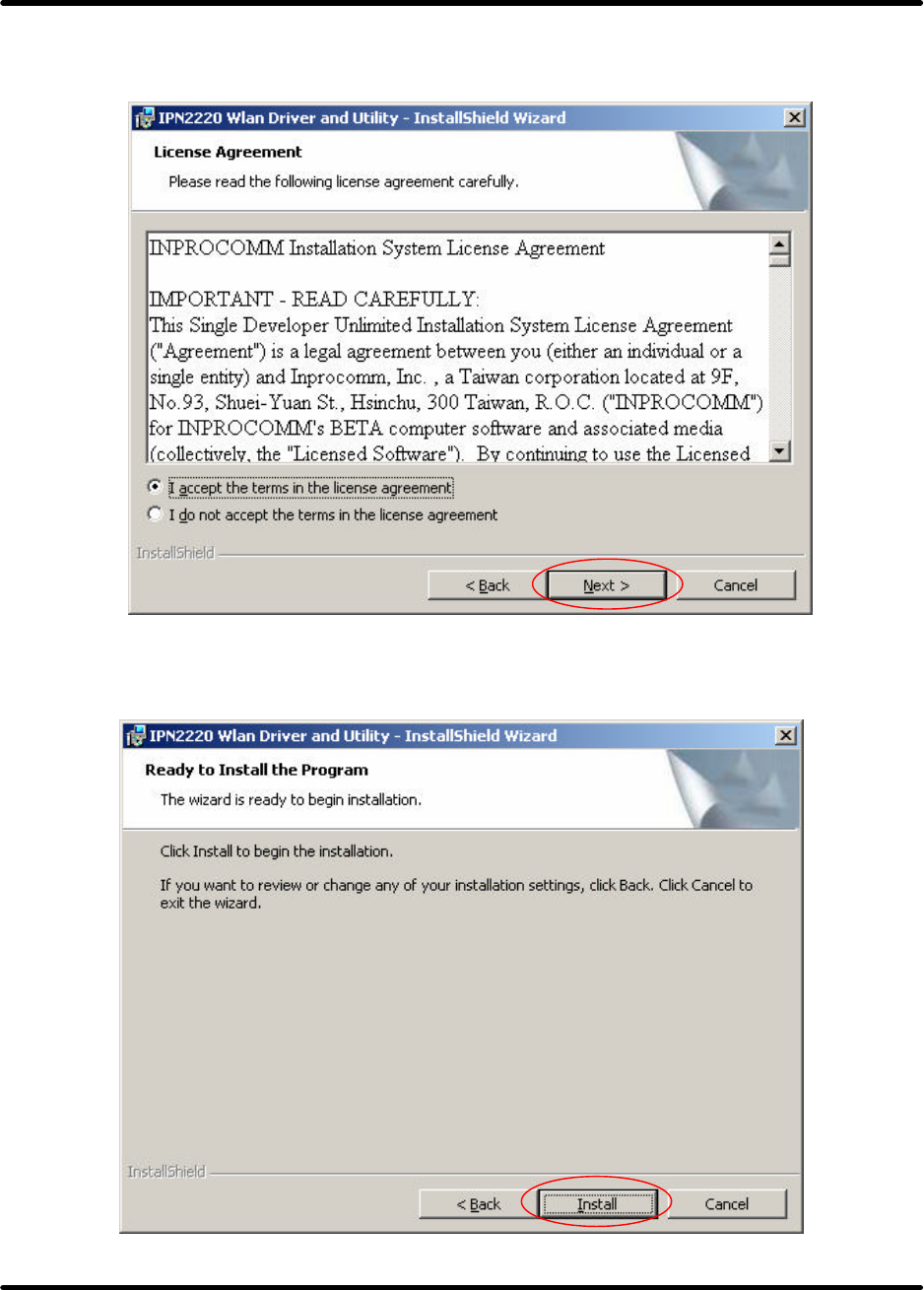
3. Licence Agreement ,Please choice “I accept the terms in the license agreement ” and click "Next" to
continue.
4.Click "Install" button to continue.
G101 Series WLAN Card
Page 31
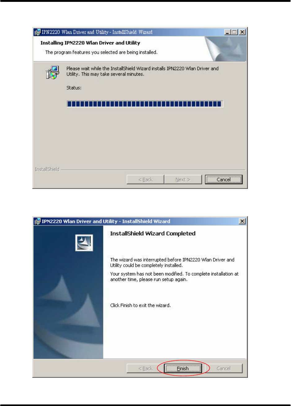
zThe driver and utility are Installing.
zClick Finish button to complete install procedure.
G101 Series WLAN Card
Page 32
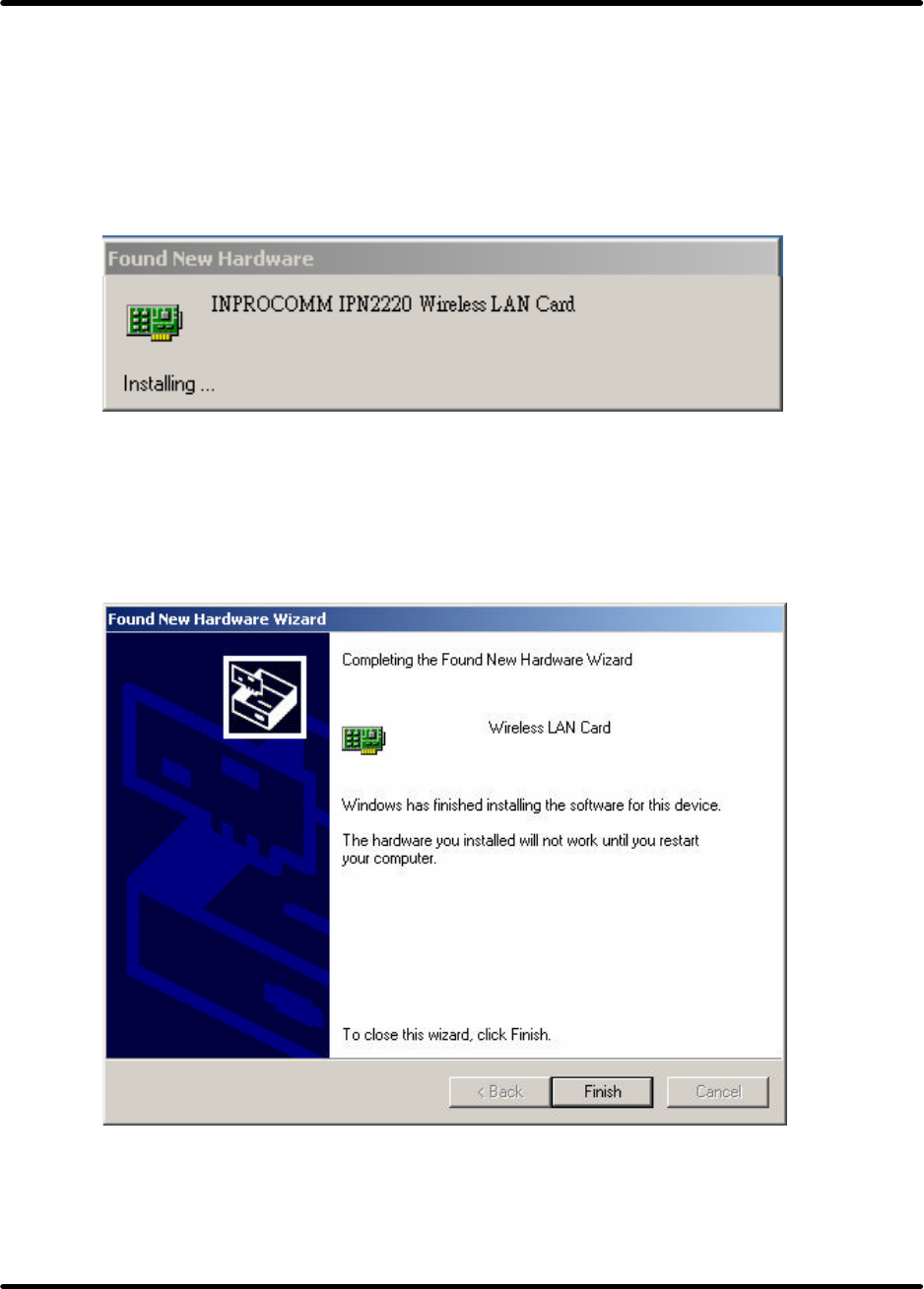
5.Insert the G101 WLAN adapter into the MiniPCI slot, the system will automatically find the device
and search for its software then the InstallShield Wizard finished installation and the system tray icon
is loaded in the taskbar (see illustration below).
Note: Please turn-off computer before user insert G101.
zFound New Hardware and Installing.
zComplete device install.
G101 Series WLAN Card
Page 33
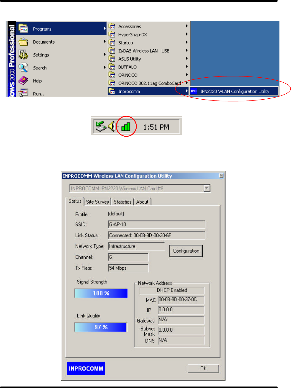
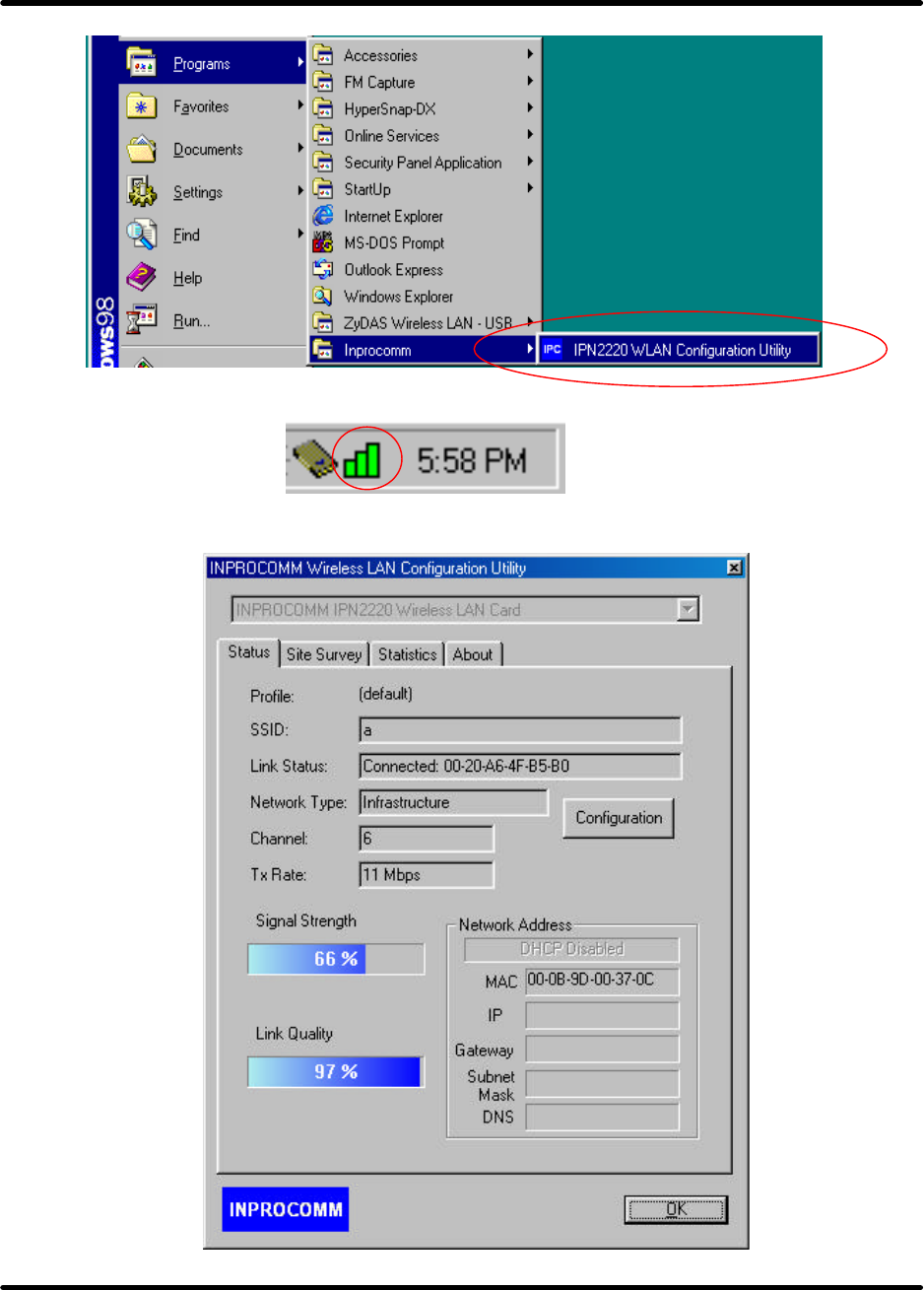
6.Please click “Start-> programs -> Inprocomm->IPN2220 WLAN Configuration Utility”.
zThe WLAN icon will appear.
7.The “WLAN Configuration Utility” screen will appear.

G101 Series WLAN Card
Page 34
For Windows 98SE
Install the Driver and Utility
1. Insert the CD into the CD-ROM device and execute the "setup.exe " program for G101 series to select.
2.The InstallShield Wizard box will appear, click "Next" to continue.
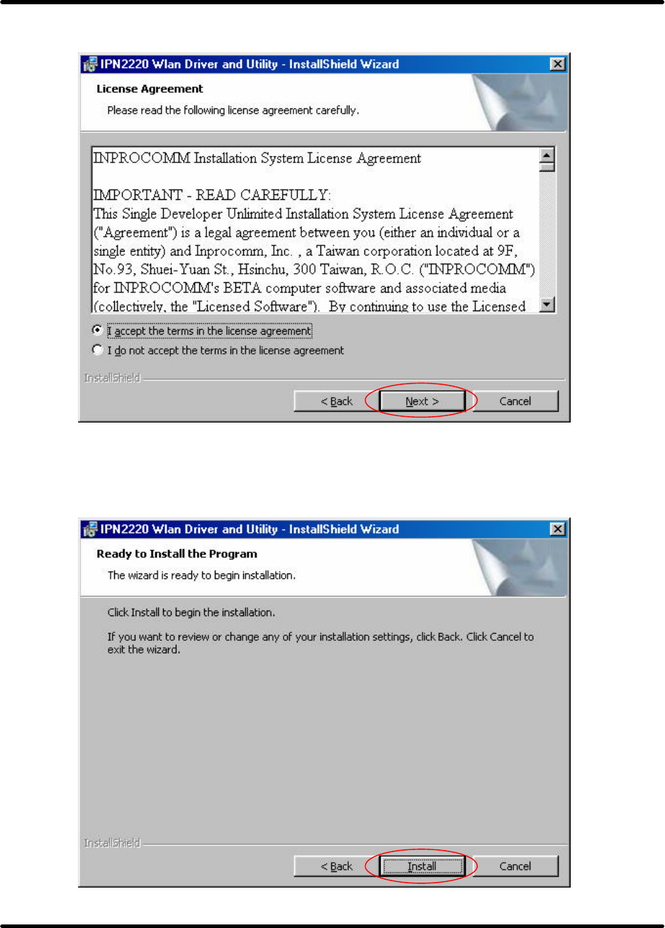
3. Licence Agreement appears. Please choice “I accept the terms in the license agreement ” and click
G101 Series WLAN Card
Page 35
"Next" to continue.
4. Click "Install" button to continue.
G101 Series WLAN Card
Page 36
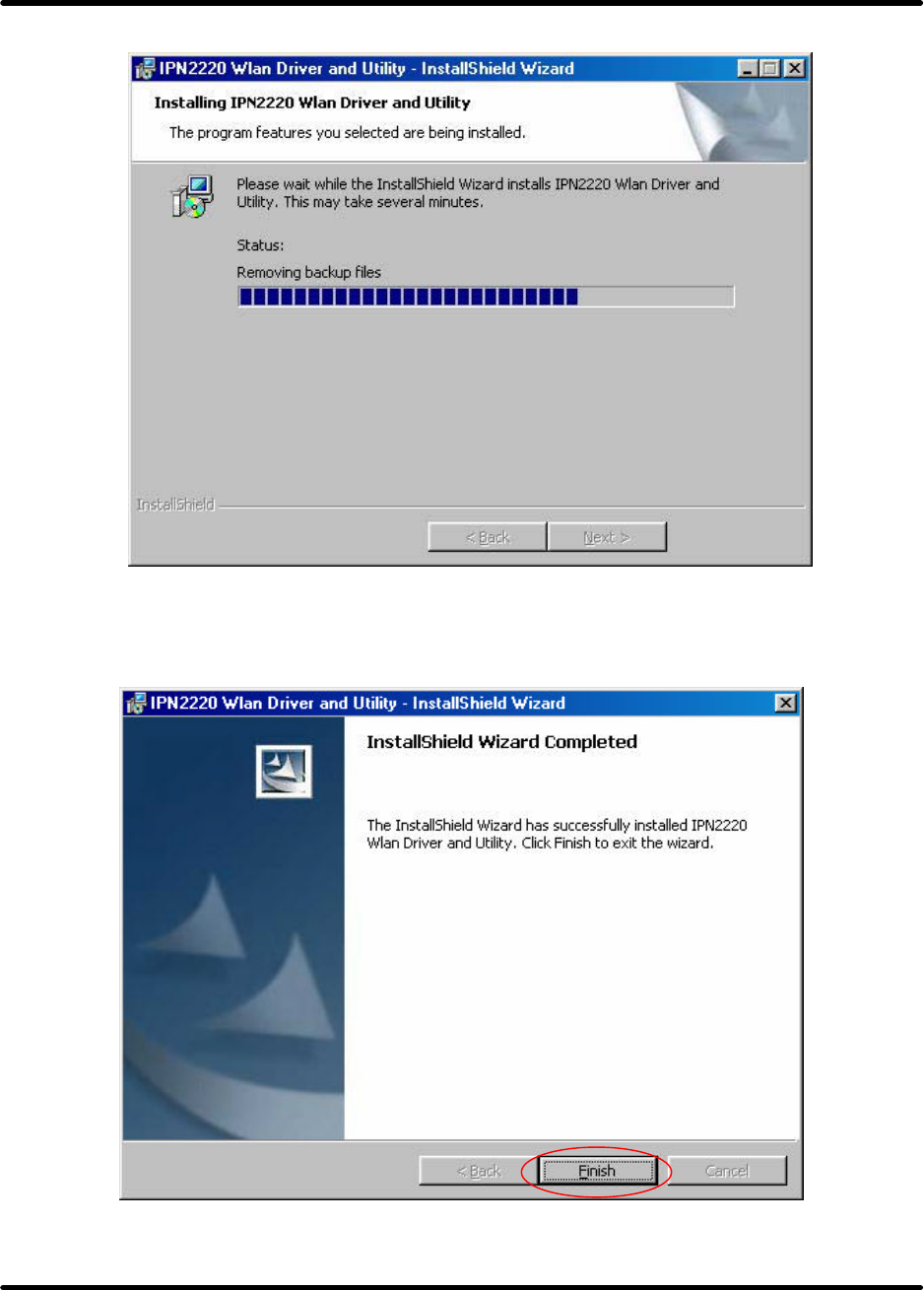
zThe driver and utility are Installing.
zClick Finish button to complete install procedure.
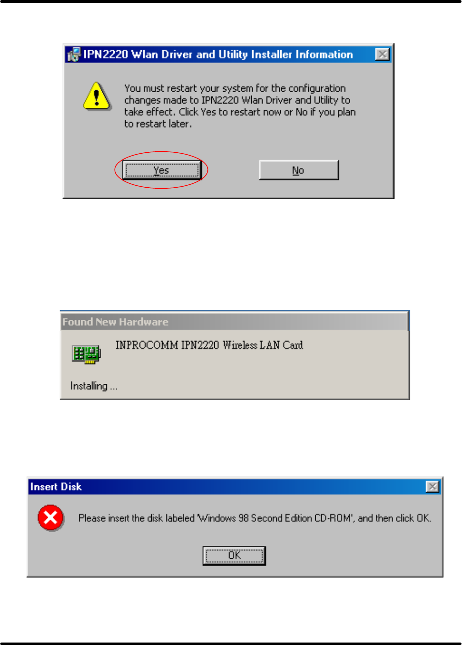
5. After running the driver package, it will be requested restart Win98 OS.
G101 Series WLAN Card
Page 37
6. Insert the G101 WLAN adapter into the MiniPCI slot. The system will automatically find the device
and search for its software then the InstallShield Wizard finished installation and the system tray icon
is loaded in the taskbar (see illustration below).
Note: Please turn off the power before you insert G101.
zNew Hardware Found
7. Please insert the disk labeled "Windows 98 Second Edition CD-ROM."
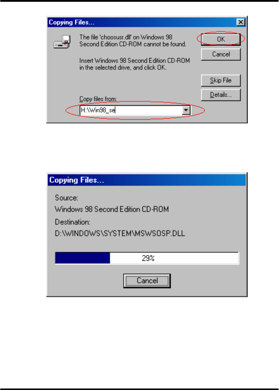
8. To choose Windows 98SE installing folder
G101 Series WLAN Card
Page 38
9. Copying Files
10. Please click “Start-> programs -> Inprocomm->IPN2220 WLAN Configuration Utility”.
G101 Series WLAN Card
Page 39
zThe WLAN icon will appear.
11. The “WLAN Configuration Utility” screen will appear.
G101 Series WLAN Card
Page 40
CONFIGURATION UTILITY
Note: The following Configuration Utility was operated under Windows 2000. (Procedures will be the
same for Windows 98SE/XP)
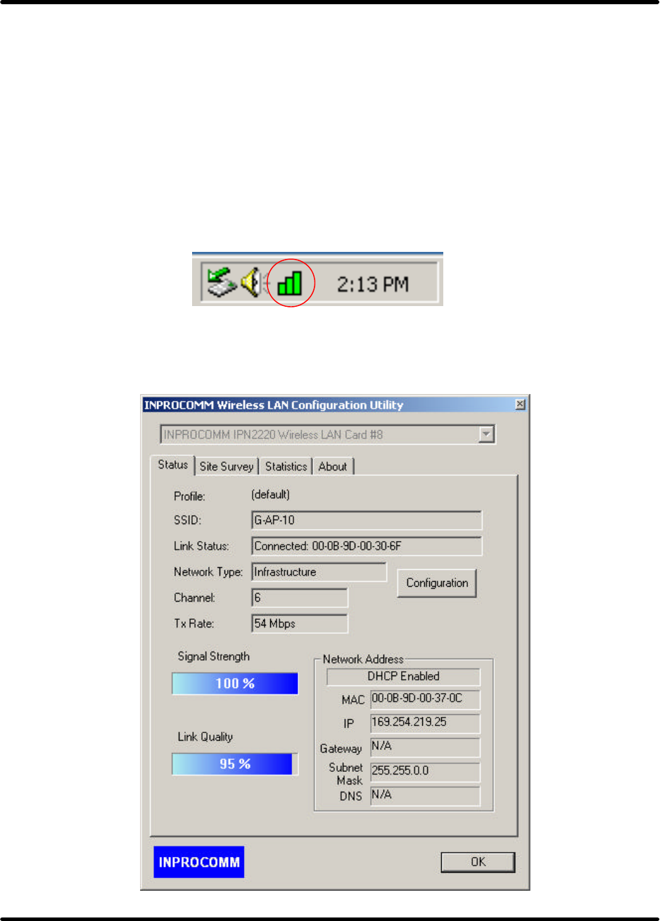
G101 uses the Configuration Utility as the management software. The utility provides an easy interface
to change any settings related to the wireless adapter. When the computer is started, the Configuration
Utility starts automatically and the system tray icon is loaded in the toolbar (see illustration belo w.)
Clicking on the utility icon will start the Configuration Utility.
Double-click on the icon shown above. The screen below will appear.
G101 Series WLAN Card
Page 41
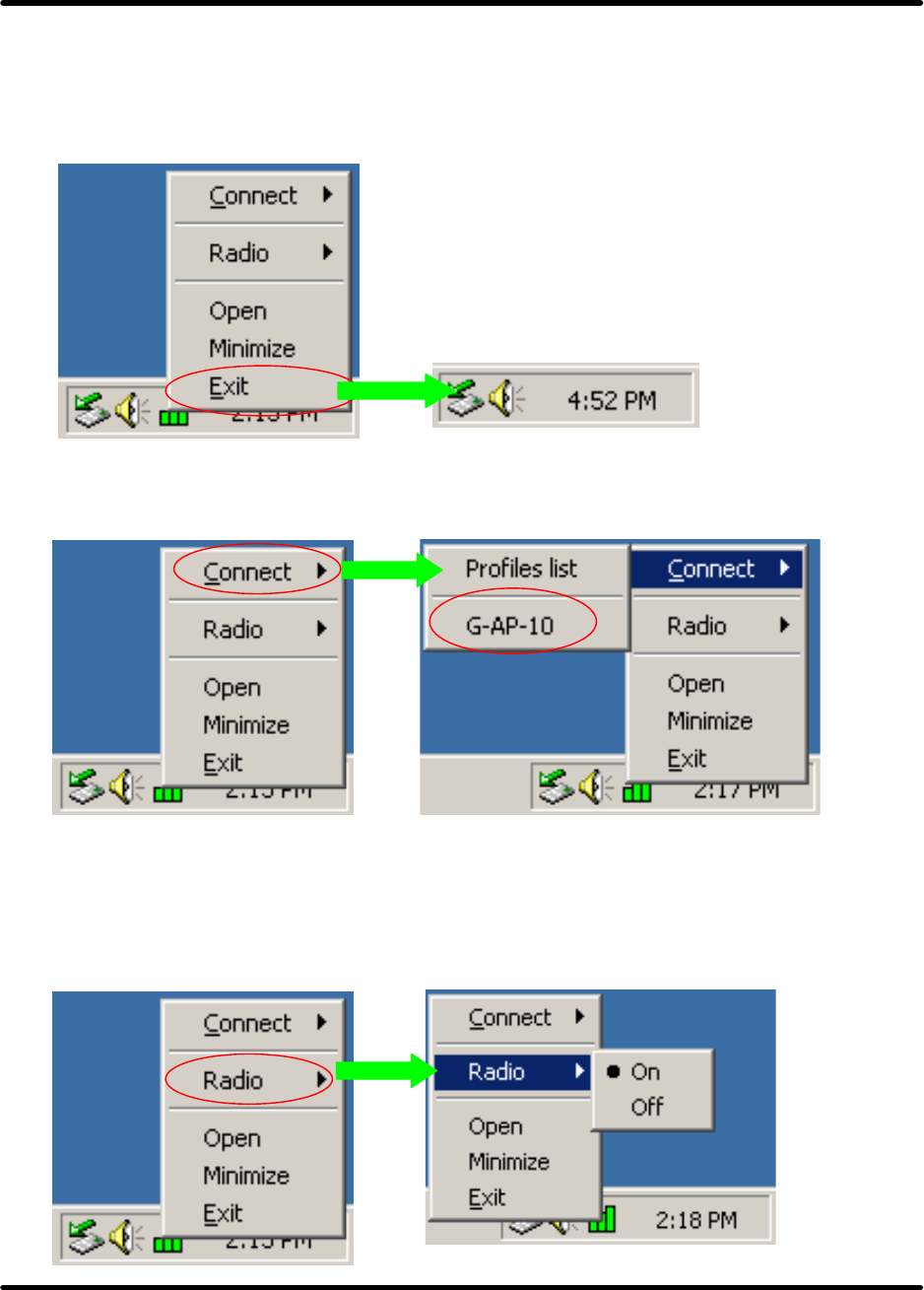
Right -click on the icon shown below. The function of utility icon will appear.
Exit
Clicking on the “Exit” Button will leave the Configuration Utility.
Connect
From “Profiles list” to select one of all profiles name (G-AP-10) to connect.
Radio
•On – Turn Radio on.
•Off – Turn Radio off.
G101 Series WLAN Card
Page 42
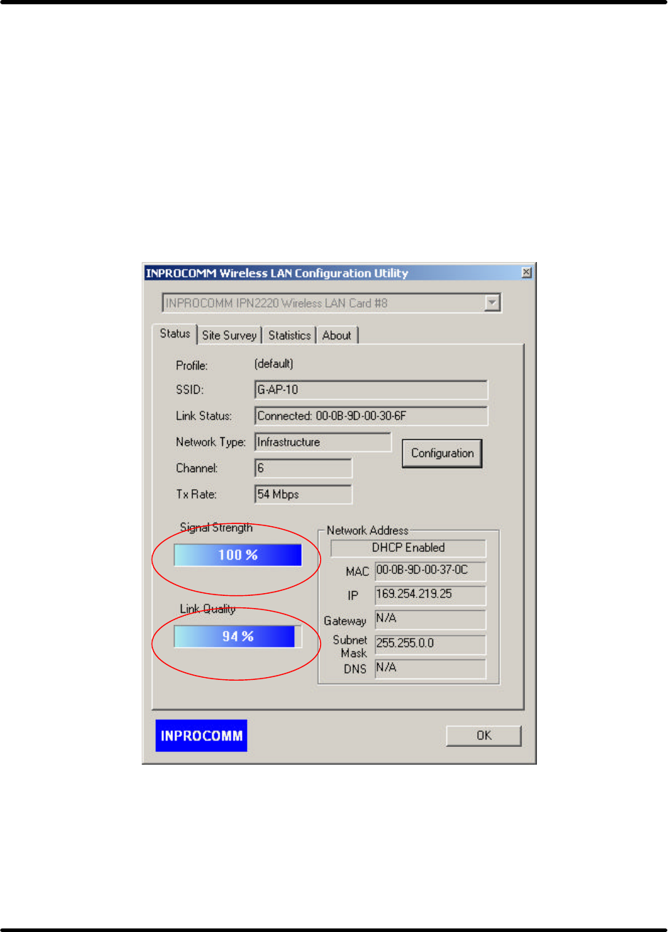
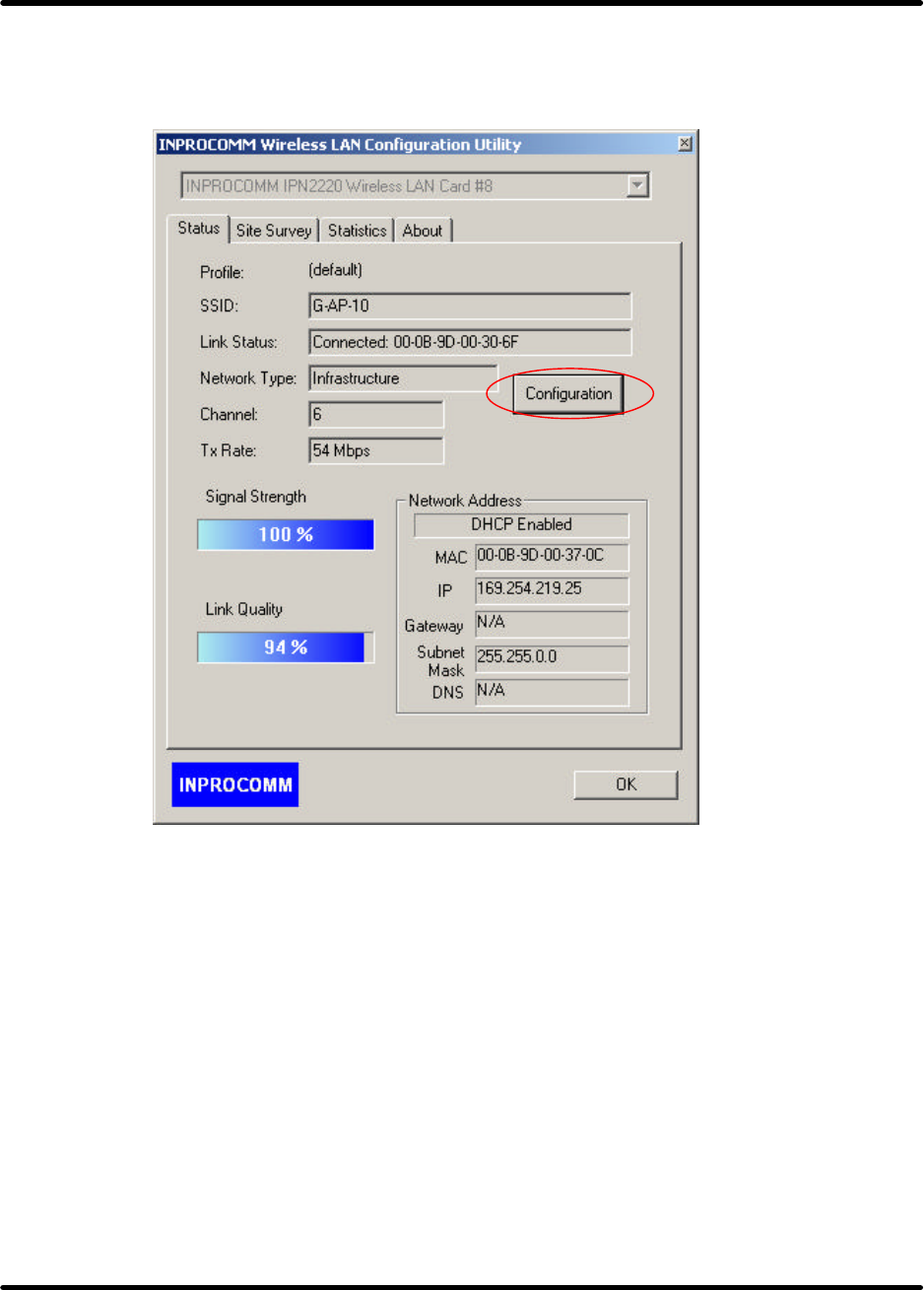
Status Tab
Signal Strength
This bar shows the signal strength level. The higher percentage shown in the bar, the more radio signal
been received by the adapter. This indicator helps to find the proper position of the wireless device for
quality network operation.
Link Quality
This bar indicates the quality of the link. The higher the percentage, the better the quality.
G101 Series WLAN Card
Page 43
Configuration Table
Click the “Configuration Button” to get into the Configuration Table, as shown below.
G101 Series WLAN Card
Page 44
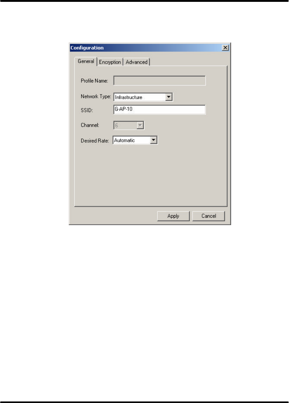
General Tab
Any of the fields shown below can be changed without re-starting the OS.
Profile name
A profile is a named set of operating parameters for the G101 WLAN adapter to display the available
profiles for the G101 WLAN adapter.
Network Type
The G101 WLAN adapter can operate in one of two modes, which are specified in the Mode field of the
Configuration menu. Clicking the down arrow at the right of the Mode field displays the available
modes.
•Ad-Hoc Station- This is the 802.11b/g Ad-Hoc mode of operation. In “Ad-Hoc” mode, only one
wireless “ cell ” is supported for each different NETWORK NAME. All communication is done from
client to client without the use of an Access Point. “Peer-to-Peer” networking uses the same NETWORK
NAME for the wireless adapters in establishing the network connection. When “Ad-Hoc ” mode is
selected, the utility will provide a selection for setting the channel.
•Infrastructure Station- This mode of operation requires the presence of an 802.11b/g Infrastructure.
All communication is done through the Infrastructure, which relays packets to other wireless clients as
well as to nodes on a wired Ethernet network.

G101 Series WLAN Card
Page 45
SSID
The name of the wireless network. This name cannot be longer than 32 characters. The default value is
“any”, which will automatically scan and connect the best performance Access point nearby. User may
specify a SSID for the adapter and then only the device with the same SSID can interconnect to the
adapter.
Channel
When communicating in Ad-Hoc mode, User must specify a channel on which communications will
take place. This field is grayed in infrastructure mode because the Access Point automatically selects the
channel.
Desired Rate
The Transmit Rate field specifies the rate at which the radio in user’s G101 WLAN adapter transmits
and receives data. User can set this to the following fixed rates: 1 Mbps; 2 Mbps; 5.5 Mbps; 6 Mbps; 9
Mbps; 12 Mbps; 18 Mbps; 24 Mbps; 36 Mbps; 48 Mbps or 54 Mbps.
Automatic - When it is enabled, the device will choose the most suitable transmission rate
automatically.
Apply
Click “Apply” button to save and implement the new settings.
G101 Series WLAN Card
Page 46
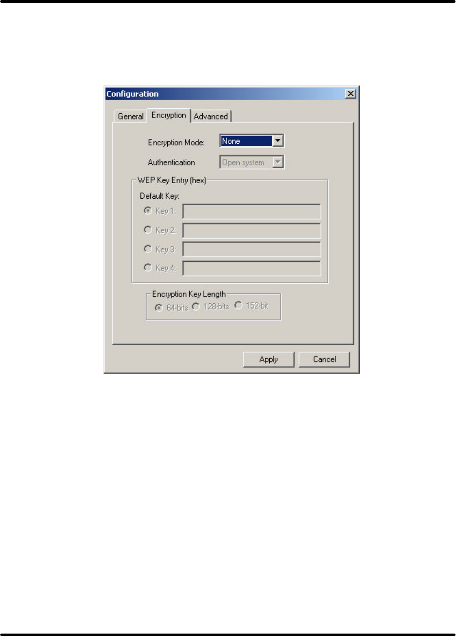
Encryption Tab
To allows to enhancing the security of a network. Every station in a secured network should enable the
Encryption function and the values of the Network Key should be the same.
Encryption Mode
•None – Disable to Encryption Tab.
•WEP – Enable to Encryption Tab.
Authentication
This setting has to be consistent with the wireless devices, which the adapter intends to connect.
•Open System – No authentication is needed among the wireless devices.
•Shared Key – Only wireless devices using a shared key (WEP Key identified) are allowed to
connecting each other. Setup the same key as the wireless devices, which the
adapter intends to connect.
•Auto Swith – Auto switch the authentication algorithm depending on the wireless devices, which the
adapter is connecting to.
Default Key
Select one of the keys (1~4) as the encryption key.
G101 Series WLAN Card
Page 47
Key Value
The keys are used to encrypt data transmitted in the wireless network. Fill the text box by following the
rules below.
•64-bit – Input 10 digit Hex values (in the “A-F”, “a- f” and “0-9”range) as the encryption keys. For
example: “0123456aef“.
•128-bit – Input 26 digit Hex values (in the “A-F”, “a-f” and “0 -9” range) as the encryption keys. For
example:“01234567890123456789abcdef“.
•152-bit – Input 32 digit Hex values (in the “A-F”, “a-f” and “0 -9” range) as the encryption keys. For
example:“012345678901234567890123456789ab “.
Encryption Key Length
One may select the 64-bit or 128-bit or 152-bit to encrypt transmitted data. Larger key length will
provide higher level of security, but the throughput will be lower.
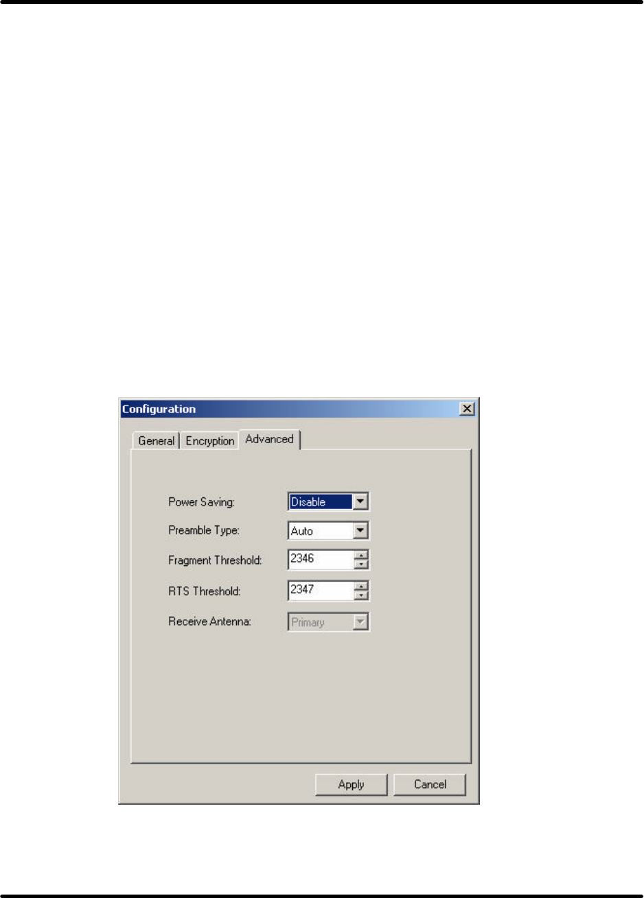
Advanced Tab

G101 Series WLAN Card
Page 48
Power Saving
Power Saving mode allows to using reduced power during idle time by going into “sleep” mode, saving
energy costs.
•Disable –The card will always set in active mode.
•Enable(Fast) –Enable the card in the power saving mode when it is idle, but some components of the
card is still alive. In this mode, the power consumption is larger than “Max“ mode.
•Enable(Max) –Enable the card in the power saving mode when it is idle.
Preamble Type
defines the length of CRC block in the frames during the wireless communication.
•Long –“Long ” can provide more reliable communication.
•Short –“Short ” is suitable for high traffic wireless network.
•Auto –the card will auto switch the preamble mode depending on the wireless networks card is
connecting to.
Fragment Threshold
The value defines the maximum size of packets, any packet size larger than the value will be fragmented.
If user have decreased this value and experience high packet error rates, user can increase it again, but it
will likely decrease overall network performance. Select a setting within a range of 256 to 2346 bytes.
Minor change is recommended.
RTS Threshold
Minimum packet size required for an RTS (Request To Send). For packets smaller than this threshold,
an RTS is not sent and the packet is transmitted directly to the WLAN. Select a setting within a range of
0 to 2347 bytes. Minor change is recommended
Receive Antenna
Define the receive antenna. If “Diversity” is selected, the card will auto switch to the antenna with high
signal strength to receive data.
G101 Series WLAN Card
Page 49
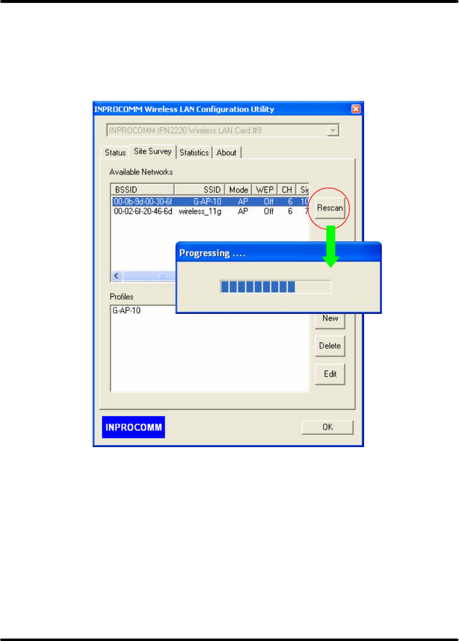
Site Survey Tab
Available Network
This screen shows all Access Points or Adapters nearby when operating in Infrastructure Station mode.
If it is intended to connect to any device on the list, double-click the item on the list, and the adapter will
automatically connect to the selected device.
•Rescan –Click “Rescan” button to collect the BSSID, SSID, Mode, WEP, CH, Signal and Support
Rates information of all the wireless devices nearby.
G101 Series WLAN Card
Page 50
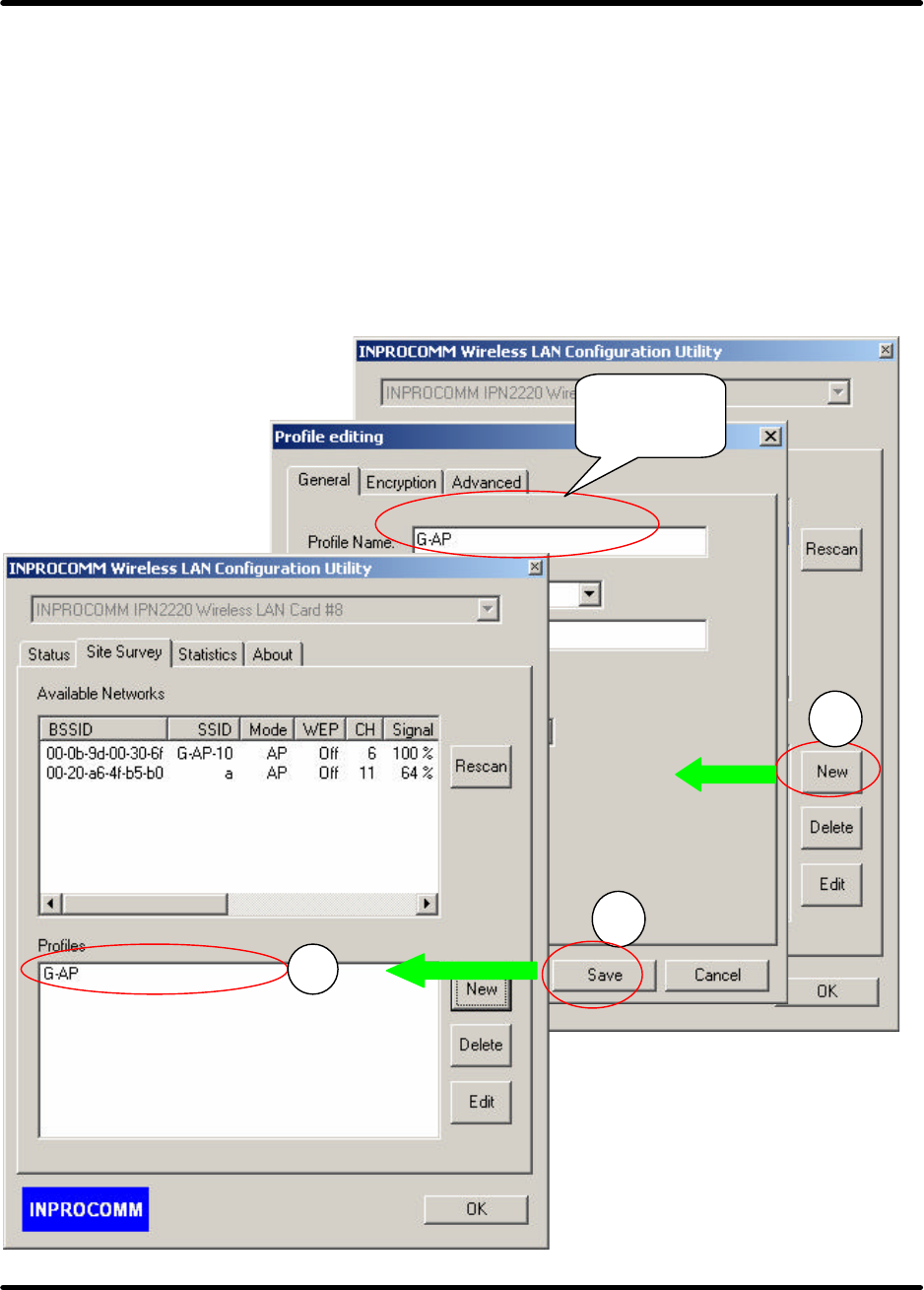
Profiles
A profile is a named set of operating parameters for user ’s G101 WLAN adapter. The Profile Page lets
user set values for all parameters by selecting a previously defined profile. Profile Page to display the
available profiles for user’s G101 WLAN adapter.
•New – 1. Click the “New” button to edit information of operating parameters for user’s G101 WLAN
adapter.
2.Click the “Save” button to save information of operating parameters for your “G-AP”
profiles of user defined
3.The Profiles Page shows “G-AP”
1
2
3
User
Define
d
G101 Series WLAN Card
Page 51
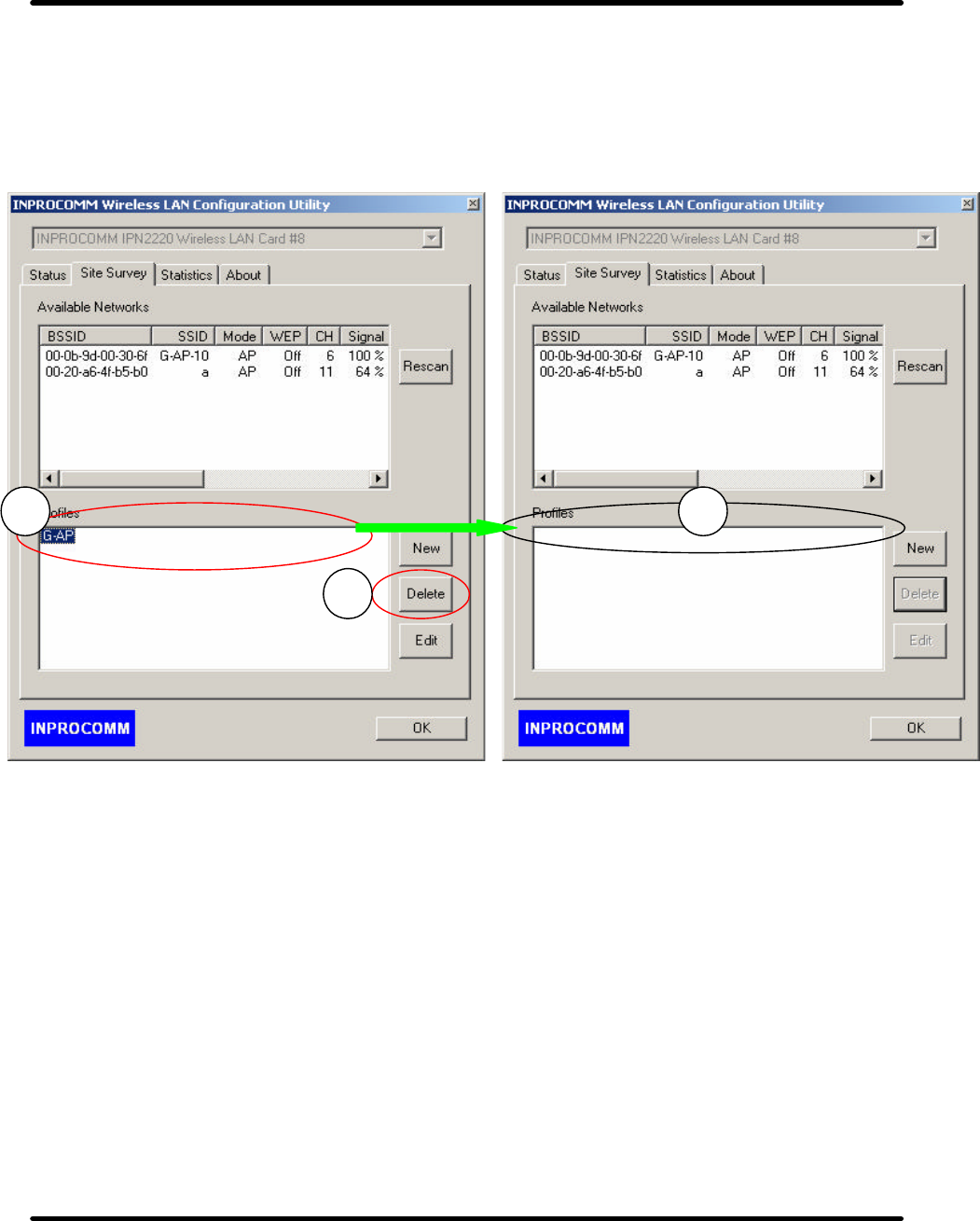
•Delete – 1.Click the item on the list.
2.Click “Delete” button.
3. delete “G-AP-10” profiles.
1
2
3
G101 Series WLAN Card
Page 52
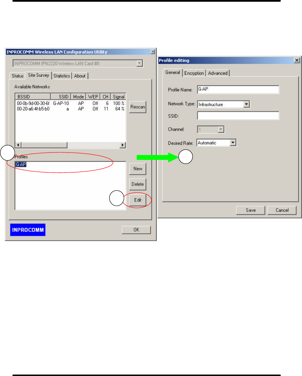
•Edit – 1.Click the item on the list.
2.Click “Edit” button.
3. Edit values for all parameters to “G-AP” profiles.
2
3
1
G101 Series WLAN Card
Page 53
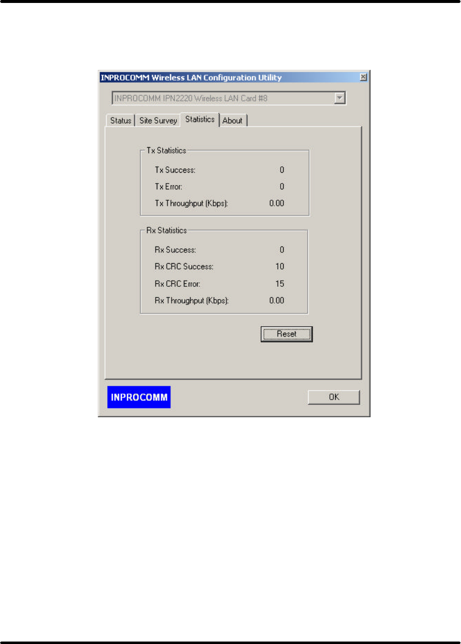
Statistics Tab
This option enables user to view the available statistic information with its Tx counts (Tx success, Tx
error), Tx throughput, and its Rx counts (Rx success, Rx error), Rx Throughput.
G101 Series WLAN Card
Page 54
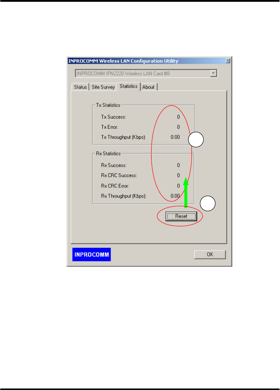
Reset– 1.Click “Reset” button.
2.All content of Tx Statistics and Rx Statistics are being zero.
1
2
G101 Series WLAN Card
Page 55
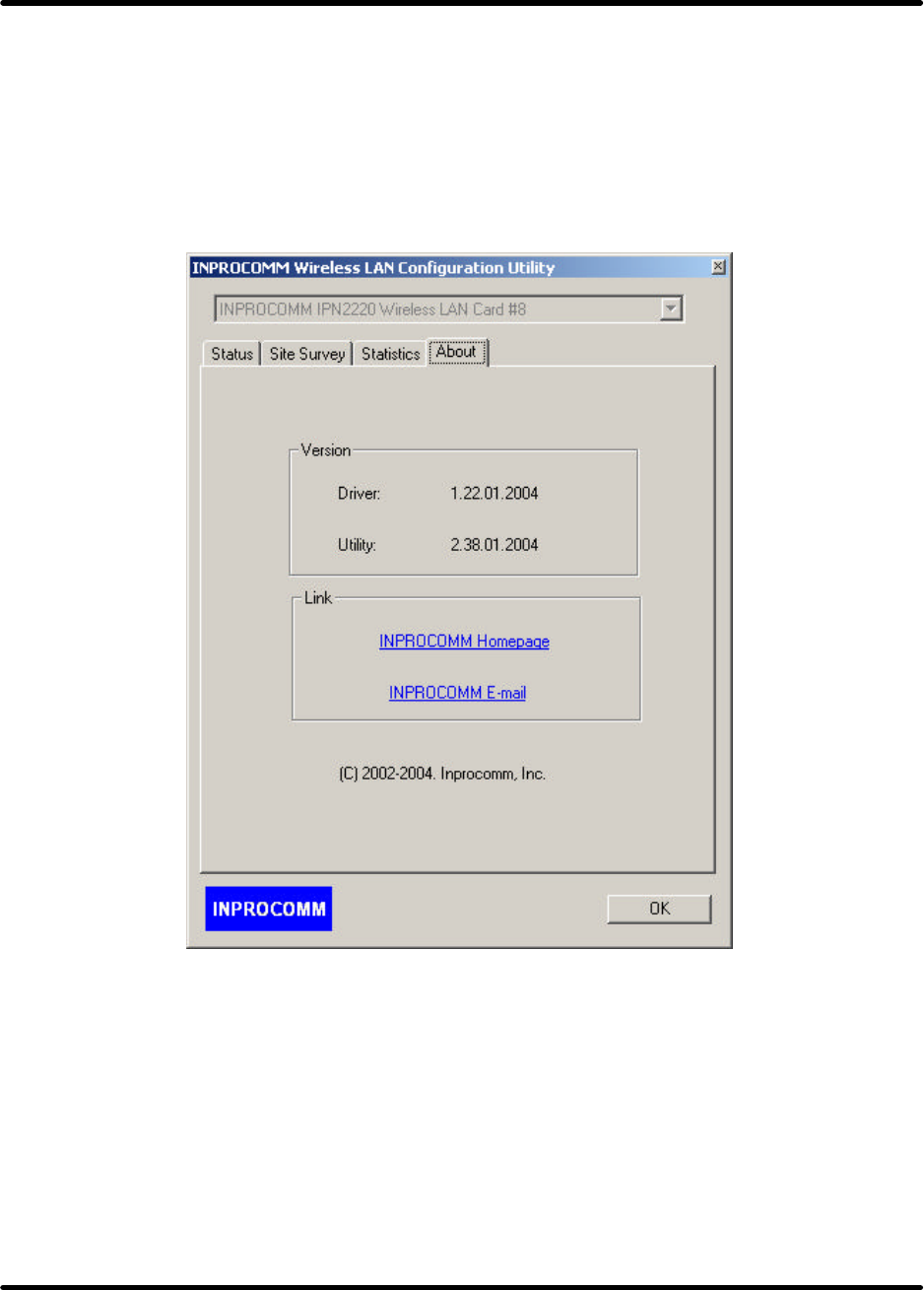
About Tab
The Information Page provides information on the version of the Network Driver, the Configuration
Utility. In addition, this page also provides the HomePage and E-mail for service, as shown in the
following illustration.

G101 Series WLAN Card
Page 56
SOFTWARE INSTALLATION FOR LINUX
NOTE 1: Before driver install, Please make sure below.
zSystem Environment:
Linux kernel 2.4
Wireless tool 16.
NOTE 2:
zFeature list:
1. Full compliance with IEEE 802.11b/g standard
2. Support short preamble
3. Support RTS/CTS mechanism
4. Support de-fragmentation at receiving
5. Auto channel selection at system startup
6. Support static WEP keys of 64 and 128 bits
zKnown issues:
1. Multicast Test is not supported.
2. Power save has not been implemented yet.
3. Data payload has not been tested yet.
4. Support for big-endian platform has not been implemented.
The Station Driver provides IEEE 802.11g station functionality. This document covers its
available I/O control commands on Linux platform.
To describe I/O control command support by IPN2220 Station on Linux platform. This can be a
user interface developer’s reference to provide users a WEB or command -line based control
environment.
1. Installation steps:
Step 1: Execute "insmod –f IPN2220STA.o "
at the directory where the IPN2220STA.o is located. By default, the STA will find a
non-WEP AP with the most powerful signal strength to join.
Step 2: Execute "./iwconfig"
to display connection status
Step 3: Execute "ifconfig wlan0 192.168.xxx.xxx"
to assign an IP to STA. Notice that “wlan0 ” is the device name of our STA.

G101 Series WLAN Card
Page 57
After step 3, the connection is established.
2. Network related setting:
zItem 1: To change the MAC address of IPN2220 station, execute
“./ifconfig wlan0 hw ether xxxxxxxxxxxx” (xxxxxxxxxxxx denotes the new MAC address
user want to set)
before user specify an IP address to the IPN2220 station.
zItem 2: To perform site survey,
execute
"./iwlist wlan0 scanning"
to scan all channels and display the scan results. Notice that the wireless-extension version
should be at least 15 for iwlist/iwconfig utilities to execute this command.
zItem 3: To join a different BSS,
execute
"./iwconfig wlan0 essid XXX" (XXX denotes the essid of AP you want to join)
zItem 4: To specify the channel of the ad-hoc network user want to create,
execute,
“./iwconfig wlan0 channel N” (N denotes the channel of the ad-hoc network user want to
create, from 1 to 11)
zItem 5: To change from infrastructure mode to ad-hoc mode,
execute
"./iwconfig wlan0 mode ad-hoc"
then execute
"./iwconfig wlan0 essid XXX" (XXX means the essid user want to set/join to the IBSS
network)
zItem 6: To change from ad- hoc mode to infrastructure mode,
execute
"iwconfig wlan0 mode managed"
then execute
"./iwconfig wlan0 essid XXX" (XXX means the essid of AP you want to join)
zItem 7: To join different BSS,
execute

G101 Series WLAN Card
Page 58
"./iwconfig wlan0 essid XXX" (XXX means the essid of AP you want to join)
3. Network related setting:
zTo enable WEP or change WEP key, please refer to the instructions below:
(1) To set WEP key to key set $i, enable WEP and use key set $i as WEP key, the command is
"./iwconfig wlan0 key xxxxxxxxxx [$i]" ,(xxxxxxxxxx denotes WEP key)($i:1~4)
(2) If user execute "./iwconfig wlan0 key xxxxxxxxxx" ,(xxxxxxxxxx denotes the WEP key)
without specifying the key ID "[$i]", then the default WEP key ID will be 1.
(3) To disable WEP at any time, the command is "./iwconfig wlan0 key off".
(4) To enable WEP that you have set before via (1) or (2) or (3), the command is "./iwconfig
wlan0 key on".
(5)To enable WEP and use key set $i as WEP key.($i can be 1~4) that you have set before via
(1) or (2) or (3), the command is "./iwconfig wlan0 key [$i]"
zIf user want to join a BSS with different WEP key setting, execute the following two
command.
(1) "./iwconfig wlan0 key xxxxxxxxxx", (xxxxxxxxxx denotes WEP key)
(2) "./iwconfig wlan0 essid XXX", (XXX denotes the essid of AP you want to join)
(3)Notice, the executing sequence is unrelated in infrastructure mode. But in ad-hoc mode,
user must execute (1) first or user will create an ad-hoc network with the same SSID but
different WEP setting.
4. Remove step:
zTo turn off STA and remove the module,
execute
"ifconfig wlan0 down" then execute
"rmmod IPN2220STA"

G101 Series WLAN Card
Page 59
TROUBLESHOOTING
If there is any problem G101 WLAN adapter or it is required to confirm whether the adapter is installed
properly or not, the following procedure is applicable to check the various components after the adapter
has been installed. The first part suggests checking the various properties of the card for checking the
proper installation. The second part lists the various problems, which might be possibly encountered
during the installation, and provides the possible solution. Check the first part to guess the probable
reason of unsuccessful installation.
Please check the followings when encountering a problem on installing the G101, or when the G101 is
non- functional.
In Windows 2000:
To check if the G101 is installed properly, please do the following:
1. Check the Windows 2000 Diagnostics. See if there is any conflict in the Resource allocation or the
I/O Address, IRQ allocations. If it is found that the IRQ or I/O Addresses are already assigned to some
other devices, change that value.
2. Go to the Control Panel. Double click on the Network Adapter, and “G101 Wireless Adapter” is
shown. Double clicking on that will show the status of the G101 network adapter. If there are no error
signs, the adapter has been installed properly.
In Windows XP:
To check if the G101 is installed properly, please do the following:
1. Go to START>CONTROL PANEL. Double-click on Network Connections. Right-click on LAN.
Click Properties.
2. The G101 network adapter will appear, indicating proper installation.

G101 Series WLAN Card
Page 60
TECHNICAL SPECIFICATIONS
Networking Characteristics
Compatibility zIEEE 802.11 Standard for WLAN (DSSS)
zWi-Fi certified by Internal
Host OS Windows 98SE/ME/2000/XP, Linux
Media Access Protocol CSMA/CA with ACK
Network Protocol TCP/IP, IPX, NetBEUI
RF Characteristics
Frequency Range 2.400-2.4835 GHz, Direct Sequence Spread Spectrum (DSSS)
Operating Channels
z1-11 United States (FCC)
z1-11 Canada (DOC)
z1-14 Japan (MKK)
z1-13 Europe (Except Spain and France) (ETSI)
Modulation Technique zOFDM with BPSK, QPSK, 16QAM, 64QAM (11g)
zDBPSK, DQPSK, CCK (11b)
Spreading 11-chip Barker Sequence
Transmit Power z17 dBm @ 11Mbps
z13 dBm @ 54Mbps
Receive Sensitivity z11 Mbps 10-5 BER @ -83 dBm
z54 Mbps 10-5 BER @ -67 dBm
Security z64/128/152-bit WEP Encryption
zWPA, TKIP, AES Data Encryption
Operating Range Open Space:100 ~ 300m; Indoor: 30m ~ 100m
The transmission speed varies in the surrounding environment.
EMC Certification FCC Class B part 15B, 15C; R&TTE
The equipment version marketed in US is restricted to usage of the channels 1-11 only.

G101 Series WLAN Card
Page 61
FCC CAUTION
1. The device complies with Part 15 of the FCC rules. Operation is subject to the following two
conditions:
(1) This device may not cause harmful interference, and
(2) This device must accept any interference received, including interference that may cause
undesired operation.
2. FCC RF Radiation Exposure Statement: The equipment complies with FCCRF radiation exposure
limits set forth for an uncontrolled environment. This equipment should be installed and operated
with a minimum distance of 20 centimeters between the radiator and your body.
3. This Transmitter must not be co-located or operating in conjunction with any other antenna or
transmitter.
4. Changes or modifications to this unit not expressly approved by the party responsible for compliance
could void the user authority to operate the equipment.
NOTE:
This device is approved for OEM installation. It is the responsibility of the Installer to comply with
the separation distance for satisfying RF exposure compliance and 15.19 labeling requirement that
the final end product must be labeled in a visible area with the following: “Contains TX FCC ID:
QS3WGBPR1”