Twinhead MPCT0168 Tablet PC User Manual T10Y User s Manual 081003
Twinhead International Corporation Tablet PC T10Y User s Manual 081003
UserManual.wiki
>
Twinhead
>
MPCT0168 User Manual
>
User Manual 2
Contents
1.
User Manual 1
2.
User Manual 2
User Manual 2
Navigation menu
Upload a User Manual
Namespaces
Wiki Guide
HTML
PDF
Info
Views
User Manual
Discussion / Help
Navigation
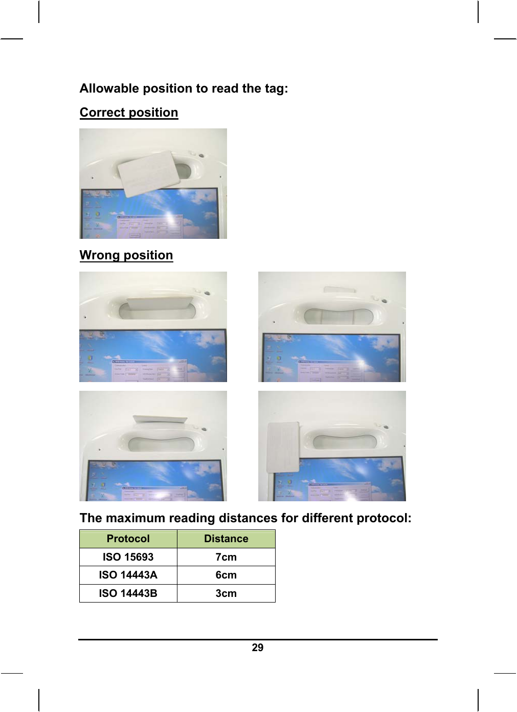
![28Information about RFID reader (Optional) The RFID reader is a compact contactless reader and writer which supports Mifare® cards and ISO14443A & ISO 14443B & ISO15693. How to use the RFID reader: Please click on [Twinhead Demo] program shown on Windows program menu to execute RFID reader software. Then press button on handle to turn on built-in RFID reader, and it will be ready to read. RFID reader will be power down after software closed. (button on handle)](https://usermanual.wiki/Twinhead/MPCT0168.User-Manual-2/User-Guide-1028143-Page-1.png)
![32Information about 3G function (Optional) Note: The system does not support 3G Voice features. The system provides 3G function (optional), please remove the SIM card cover. Then insert 3G SIM card into the slot. Attention: WLAN function will be auto turn-off when 3G function is on. Please click on [3G Watcher] program shown on Desktop to turn on 3G function. Please follow 3G Watcher Help Topics/ Wireless Data Connections/Manage profiles to create a profile first. After all settings are completed, click Connect to access Internet. User will find on Windows task bar. The indicator shows the received signal strength in dBm up to a maximum of five bars.. Please click 3G Watcher Tools/Turn Radio Off to stop connection.](https://usermanual.wiki/Twinhead/MPCT0168.User-Manual-2/User-Guide-1028143-Page-5.png)