Twisthink TT10315 M2M Device User Manual AppNoteDraft3bx
Twisthink LLC M2M Device AppNoteDraft3bx
UserManual.wiki
>
Twisthink
>
TT10315 User Manual
User Manual
Navigation menu
Upload a User Manual
Namespaces
Wiki Guide
HTML
PDF
Info
Views
User Manual
Discussion / Help
Navigation
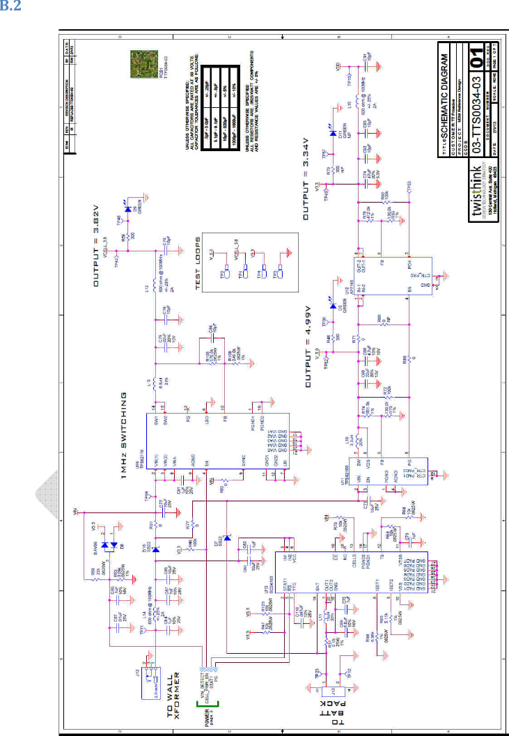
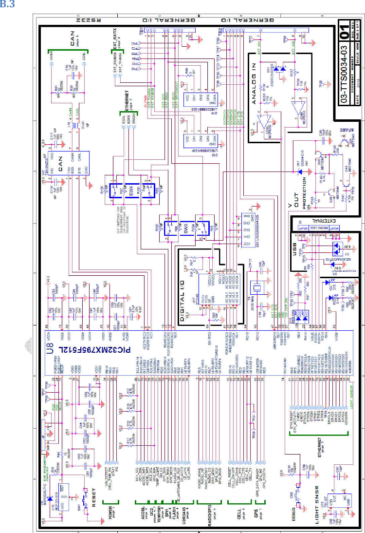
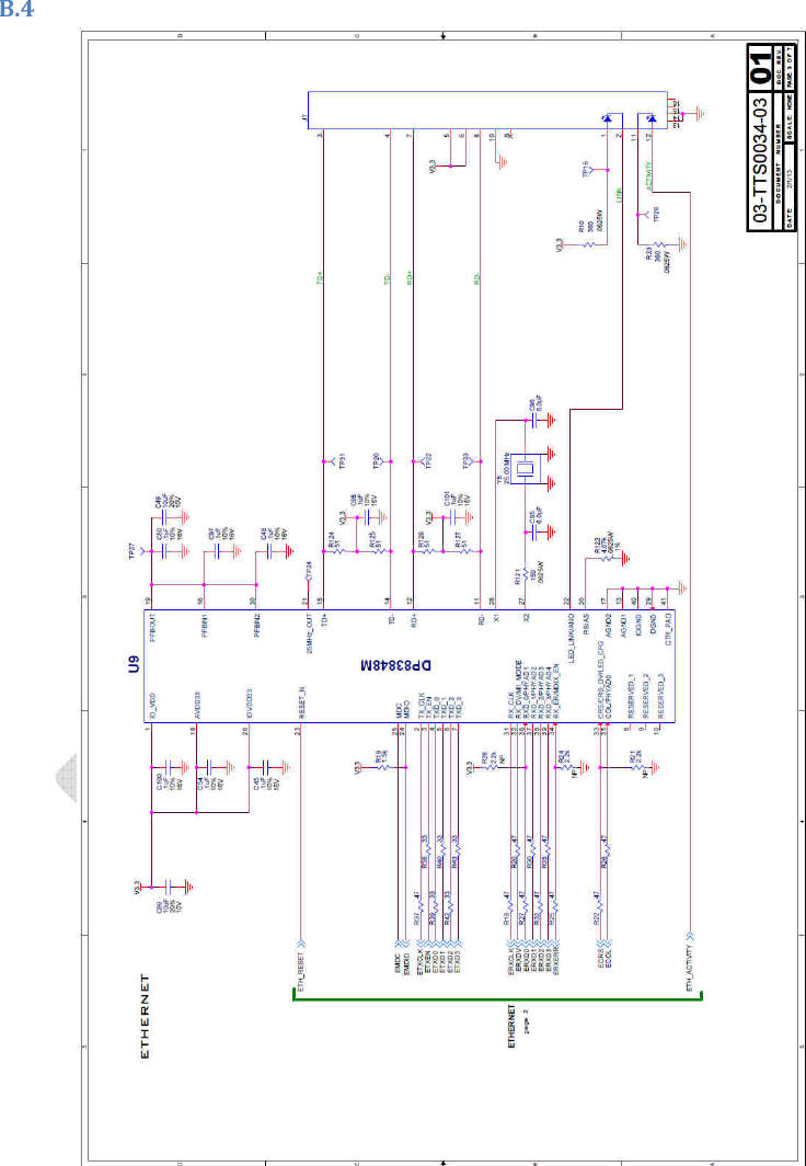
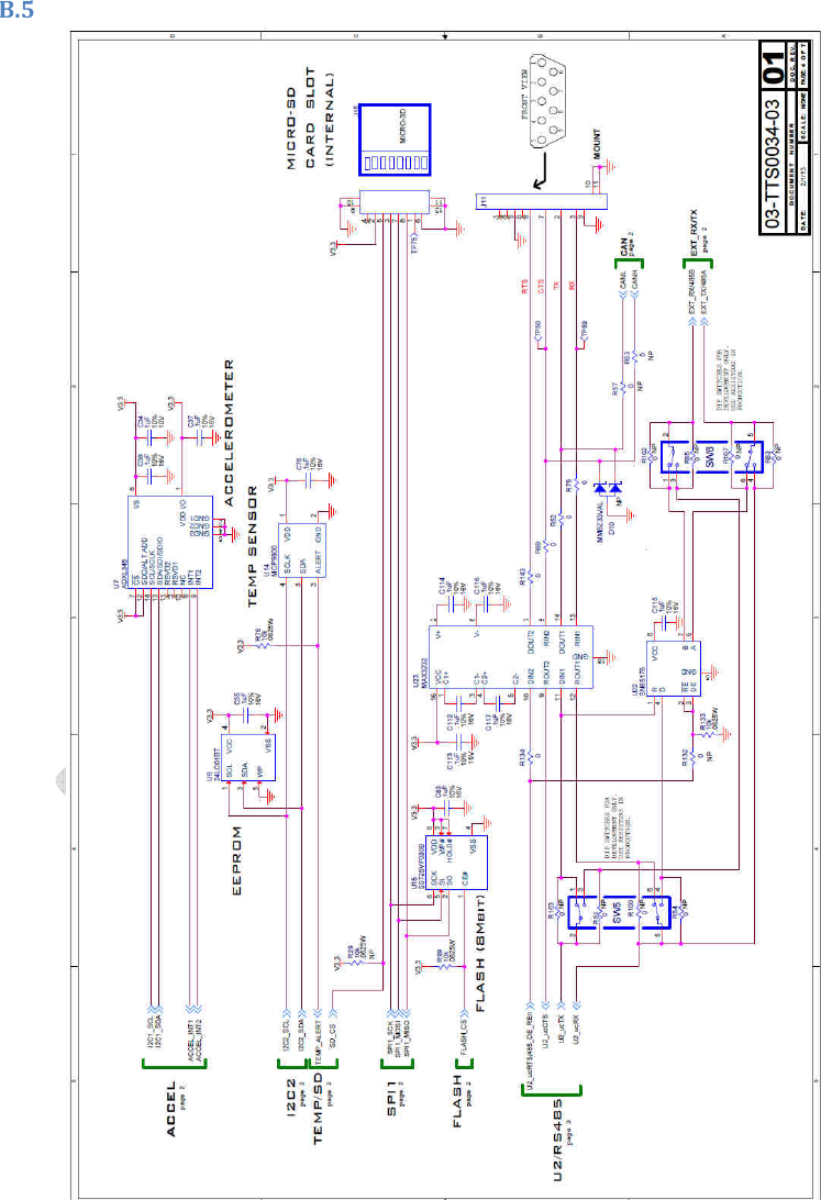
![4.1 Data Rate The cellular connection is capable of at least 50kbps data transfers while uploading or downloading. The date-rate may vary based on the environment in which the device is located. 4.2 Mesh Network Connectivity The M2M device provides Zigbee/802.15.4 for mesh network connectivity. 4.2.1 IEEE 802.15.4 When configured to support a custom 802.15.4 protocol, the device provides the necessary hardware to communicate on the network. The protocol is defined by the software in the device’s host processor and will allow the device to communicate with other devices in the network. Mesh networking allows up to four hops between devices on the network. The protocol supports a burst mode which allows a single device to send a large amount of data from itself to a gateway while ensuring that other nodes in the system do not communicate. Furthermore, since the RF sensitivity decreases during burst mode, the device checks the link margin to determine whether the link will be lost when it enters burst mode. If the link is not of sufficient quality, the device will not transmit using burst mode. 4.3 Certifications The M2M device is FCC certified for operation of the cellular and 802.15.4 radios and for operation on the Verizon Wireless CMDA network. 4.4 Programming Support 4.5.1 Wired Firmware Updates The device provides a Microchip ICSP debug/program interface (J9) for physically connecting a Microchip Real-Ice or ICD3 programmer and updating the firmware in the host Microchip PIC32. 4.5 Power Supply The purpose of the power supply in the device is to regulate the input DC voltage to voltage required by the processor and wireless module. 4.6.1Input The power supply input supports voltages between 6V and 12V. The current draw of the supply provides up to 1.5A of current draw at the supply voltage. 4.6.2 Output 4.7 Sleep Mode The device is capable of entering a low current draw sleep mode when instructed by the application software Supported? . In this mode the current draw will be less than 5mA. Exiting this mode may be triggered by a timeout, button press, or action on a digital I/O from the general purpose interface. In this mode the device is not able to use the cellular module. When the device is not communicating through the cellular module it will utilize power saving features of the module to limit the current draw of the Comment [DK1]: Sleep mode has not been proven out yet. The 5mA target will not be hit, as there are two LEDs in the power supply that are always on and will draw more… Will need to follow up on this.](https://usermanual.wiki/Twisthink/TT10315/User-Guide-1944576-Page-7.png)