Twisthink TT10315 M2M Device User Manual AppNoteDraft3bx
Twisthink LLC M2M Device AppNoteDraft3bx
User Manual

Contents
1.0 Introduction ............................................................................................................................................4
2.0 RF Exposure Information ........................................................................................................................4
3.0 Feature Overview....................................................................................................................................5
4.0 Functional Description ............................................................................................................................6
4.1 Data Rate.............................................................................................................................................7
4.2 Mesh Network Connectivity ...............................................................................................................7
4.3 Certifications....................................................................................................................................... 7
4.4 Programming Support.........................................................................................................................7
4.5.1 Wired Firmware Updates.............................................................................................................7
4.5 Power Supply ......................................................................................................................................7
4.6.1Input..................................................................................................................................................7
4.6.2 Output.............................................................................................................................................. 7
4.7 Sleep Mode .........................................................................................................................................7
4.7 Operating Temperature ......................................................................................................................8
4.8 User Interface .....................................................................................................................................8
4.8.1 LED Indicators ..............................................................................................................................8
4.8.2 Buttons.........................................................................................................................................8
4.9 General Purpose Interface ..................................................................................................................8
4.9.1 SPI................................................................................................................................................. 8
4.9.2 Digital I/O .....................................................................................................................................8
4.9.3 Analog Input.................................................................................................................................8
4.9.4 PWM Output................................................................................................................................9
4.9.5 UART.............................................................................................................................................9
4.10 Additional Interfaces.........................................................................................................................9
4.10.1 USB.............................................................................................................................................9
4.10.2 CAN ............................................................................................................................................9
4.10.3 Ethernet .....................................................................................................................................9
4.11 SD Card Support................................................................................................................................9
4.12 Sensing ..............................................................................................................................................9

4.12.1 Accelerometer..........................................................................................................................10
4.12.2Light Level .................................................................................................................................10
4.12.3 Temperature ............................................................................................................................10
5.0 Hardware Description ...........................................................................................................................10
5.1 Power and Bus Connectors ...........................................................................................................10
5.2 Communication Devices................................................................................................................10
4.3 Board Memory ..............................................................................................................................11
5.4 On-Board Sensors .........................................................................................................................11
5.5 User Interface................................................................................................................................12
5.6 PIC 32 Processor............................................................................................................................12
6.0 Getting Started..................................................................................................................................13
6.1 Signup................................................................................................................................................13
6.1.1 Obtaining the Boards MEID Number .........................................................................................13
6.1.2 Purchase a Verizon Data Plan ....................................................................................................13
6.1.3 Register With Twist M22 Developer Web Site...........................................................................13
6.2 Interacting with the Web Site ...........................................................................................................14
6.2.1 Device Tab..................................................................................................................................14
6.2.2 Dashboard Tab ...........................................................................................................................15
6.2.3Console Tab.................................................................................................................................16
6.2.4 Account Tab ...............................................................................................................................17
6.2.5 Accelerometer Tab.....................................................................................................................17
6.2.6 Thermometer Tab ......................................................................................................................17
7.0 Software API..........................................................................................................................................17
Appendix A Compiling the Project ..............................................................................................................18
A.1 Connecting the Real-ICE ...................................................................................................................19
A.1 Opening the Project..........................................................................................................................19
A.3 Making the Project and Programming the Board............................................................................19
Appendix B Board Schematics ....................................................................................................................22
B.1 ...........................................................................................................................................................23
B.2 ...........................................................................................................................................................24
B.3 ...........................................................................................................................................................25
B.4 ...........................................................................................................................................................26
B.5 ...........................................................................................................................................................27

B.6 ...........................................................................................................................................................28
B.7 ...........................................................................................................................................................29
B.8 ...........................................................................................................................................................30

1.0 Introduction
Machine to Machine (M2M) technology allows two or more devices to exchange data even though they may not have
originally been designed to communicate with each other. M2M technology bridges disparate communications
technologies to a common and universal protocol. It allows two or more devices to communicate without being tied to
a physical location.
In traditional command and control applications, data acquisition and information exchange methods such as
SCADA, wired Ethernet (802.3), wireless Ethernet (802.11) or Bluetooth require devices to be either physically wired
to a network (SCADA and 802.3), or be located near each other (802.11 and Bluetooth ). M2M uses radio technology
based on the cellular phone network. This means that M2M devices can be at opposite ends of the world, or even
mobile, and still communicate with each other.
M2M devices are viable solutions in such applications as weather balloons, asset tracking, pet collars, utility
monitoring, and many others. The Microchip M2M Development Platform for CDMA is a development platform
certified for use on the Verizon network and can be used either as a platform for developing custom M2M solutions or
used as a drop-in-place solution for existing applications.
2.0 RF Exposure Information
This product complies with FCC RF radiation exposure limits. This equipment should be installed and operated with
a minimum distance of 20 cm between the radiator and your body.
This product complies with FCC RF radiation exposure limits set forth for an uncontrolled environment. The
wireless system must not be co-located or operating in conjunction with any other antenna or transmitter.
FCC ID: ZPV-TT10315
IC: 9772A-TT10315
FCC Part 15.21 Information Regarding Un-Approved Changes or Modifications:
Changes and/or modifications not approved by the responsible party could void the user’s authority to
operate the equipment.
FCC Part 15.105 Information to the User
Note: This equipment has been tested and found to comply with the limits for a Class B digital device,
pursuant to part 15 of the FCC Rules. These limits are designed to provide reasonable protection against
harmful interference in a residential installation. This equipment generates, uses and can radiate radio
frequency energy and, if not installed and used in accordance with the instructions, may cause harmful
interference to radio communications. However, there is no guarantee that interference will not occur
in a particular installation. If this equipment does cause harmful interference to radio or television

reception, which can be determined by turning the equipment off and on, the user is encouraged to try
to correct the interference by one or more of the following measures:
• Reorient or relocate the receiving antenna.
• Increase the separation between the equipment and receiver.
• Connect the equipment into an outlet on a circuit different from that to which the receiver is
connected.
• Consult the dealer or an experienced radio/TV technician for help.
RSS-210 Compliance:
This device complies with Industry Canada RSS-210. Operation is subject to the following two conditions:
(1) this device may not cause interference, and (2) this device must accept any interference, including
interference that may cause undesired operation of the device.
RSS-210 Conformité:
Cet appareil est conforme avec Industrie Canada RSS-210. Son fonctionnement est soumis aux deux
conditions suivantes: (1) cet appareil ne doit pas provoquer d'interférences, et (2) cet appareil doit
accepter toute interférence, y compris les interférences pouvant provoquer un fonctionnement
indésirable de l'appareil.
ICES-003 Compliance Statement:
This Class B digital apparatus complies with Canadian ICES-003.
Déclaration de conformité à la norme NMB-003:
Cet appareil de classe B est conforme à la norme NMB-003 du Canada.
3.0 Feature Overview
The Microchip M2M Development Platform for CDMA is designed to provide a Verizon-certified M2M solution out-
of-the-box, as well as provide an extensible platform for custom applications. The platform provides a variety of
sensors and interfaces to allow the designer to tailor the solution for a specific application.
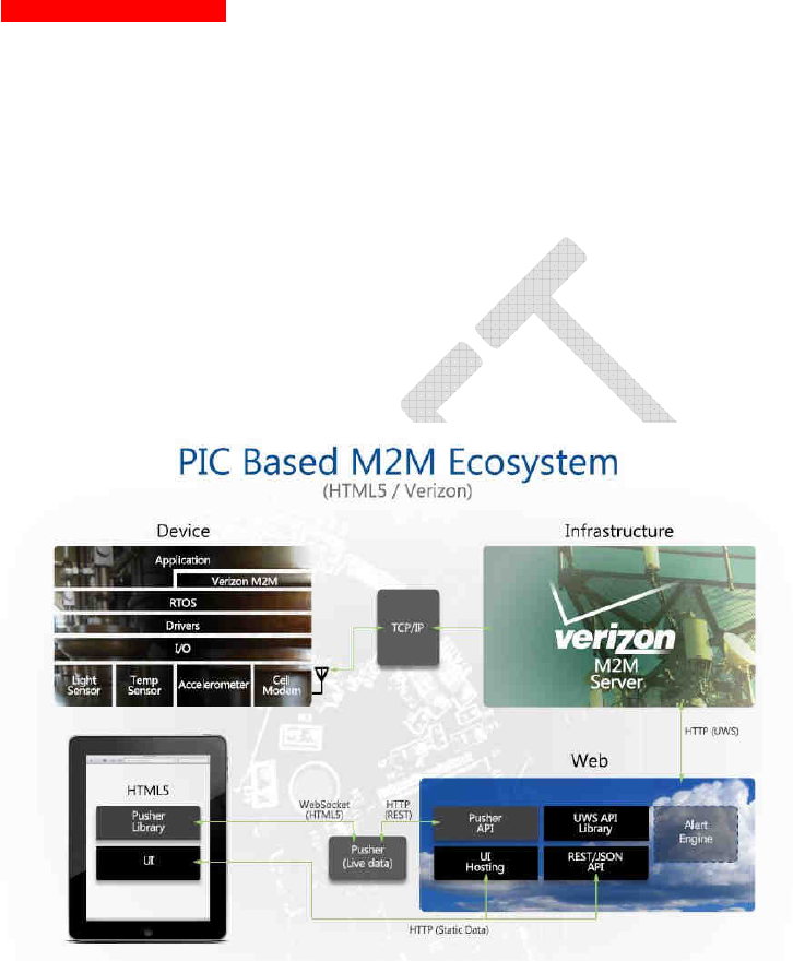
Need Functional diagram here
The software for the platform is designed to allow the developer to customize the platform for a particular
application while maintaining Verizon certification. The certified software components are the software for the cell
radio firmware and DCF (Device Client Framework) binary library, which are provided as binary modules. The DCF
API is described in section TBD of this document. The operating system, communications stacks and application
software are provided with full source code.
4.0 Functional Description
The Microchip M2M Development Platform for CDMA makes it easy to learn and develop M2M solutions that
communicate over the Verizon Mobile Network. The platform is one part of an integrated, cloud-based M2M
ecosystem. The installed platform communicates with the ecosystem via the Verizon CDMA Cell network. Data is
sent and received through the cloud-based M2M data-management center hosted by nPhase, which is owned and
operated by Verizon. The center is accessed by the user via a web portal accessible by any internet browser.
Through the portal, the user can monitor and control any number of M2M platforms.

4.1 Data Rate
The cellular connection is capable of at least 50kbps data transfers while uploading or downloading. The date-rate
may vary based on the environment in which the device is located.
4.2 Mesh Network Connectivity
The M2M device provides
Zigbee/802.15.4
for mesh network connectivity.
4.2.1 IEEE 802.15.4
When configured to support a custom 802.15.4 protocol, the device provides the necessary hardware to
communicate on the network. The protocol is defined by the software in the device’s host processor and will allow the
device to communicate with other devices in the network. Mesh networking allows up to four hops between devices
on the network. The protocol supports a burst mode which allows a single device to send a large amount of data from
itself to a gateway while ensuring that other nodes in the system do not communicate. Furthermore, since the RF
sensitivity decreases during burst mode, the device checks the link margin to determine whether the link will be lost
when it enters burst mode. If the link is not of sufficient quality, the device will not transmit using burst mode.
4.3 Certifications
The M2M device is FCC certified for operation of the cellular and 802.15.4 radios and for operation on the
Verizon Wireless CMDA network.
4.4 Programming Support
4.5.1 Wired Firmware Updates
The device provides a Microchip ICSP debug/program interface (J9) for physically connecting a Microchip
Real-Ice or ICD3 programmer and updating the firmware in the host Microchip PIC32.
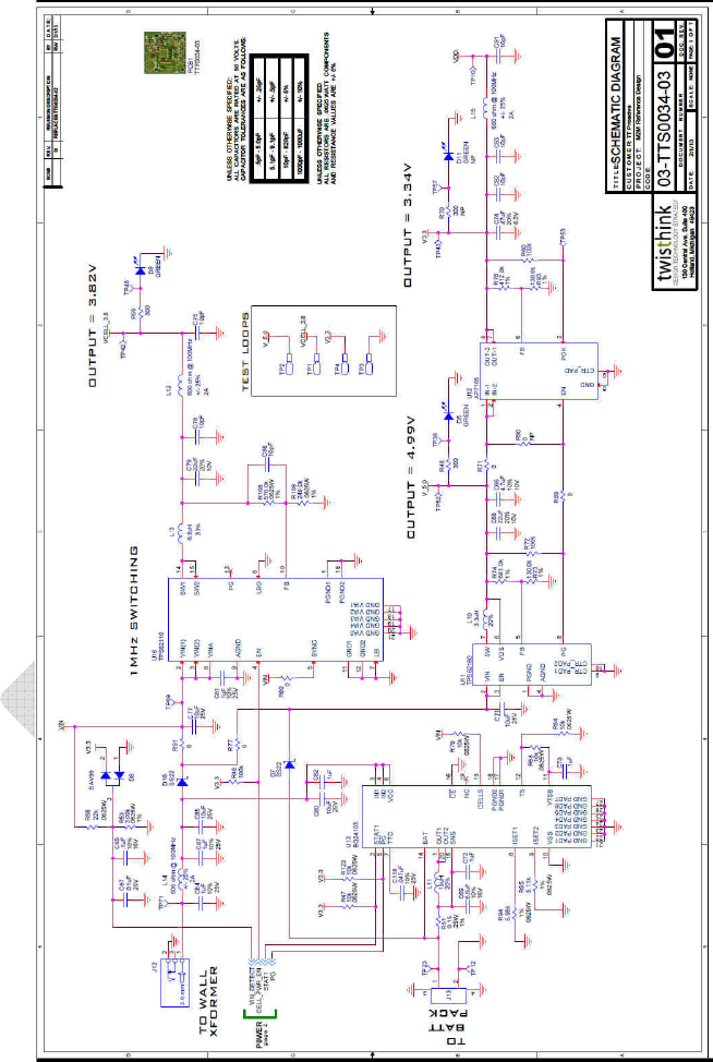
4.5 Power Supply
The purpose of the power supply in the device is to regulate the input DC voltage to voltage required by
the processor and wireless module.
4.6.1Input
The power supply input supports voltages between 6V and 12V. The current draw of the supply provides
up to 1.5A of current draw at the supply voltage.
4.6.2 Output
4.7 Sleep Mode
The device is capable of entering a low current draw sleep mode when instructed by the application
software
Supported?
. In this mode the current draw will be less than 5mA. Exiting this mode may be
triggered by a timeout, button press, or action on a digital I/O from the general purpose interface. In this
mode the device is not able to use the cellular module. When the device is not communicating through
the cellular module it will utilize power saving features of the module to limit the current draw of the
Comment [DK1]:
Sleep mode has not
been proven out yet. The 5mA target
will not be hit, as there are two LEDs in
the power supply that are always on and
will draw more… Will need to follow up
on this.

4.7 Operating Temperature
All functions of the device operate between -20C and 85°C. (Batteries may not meet this requirement)
4.8 User Interface
4.8.1 LED Indicators
The device has several LED indicators. LED’s 1,2 and 3 (D13,D14 and D15 bi-color
controlled directly by the
PIC32 firmware.
. D12 is controlled by the cell module (LED4). There are also LED indicators under the control of
the cellular module. The function of these indicators is to indicate TBD of the cellular module
Create table of LED vs
function
.
4.8.2 Buttons
Two buttons are provided. More description
4.9 General Purpose Interface
In order to support a wide range of use cases, the device contains a general purpose terminal block. This header
provides access to a wide variety of communication interfaces and features of the host processor. The functions
provided on the header are software
controlled by
the host processor application.
4.9.1 SPI
The M2M device provides an SPI communication interface through the general purpose header. The host processor
supports either master or slave roles on the SPI bus.
However both uses the same pins as the Ethernet
connection, so only one is available at a time. DIP switches are used. What are the label of the DIP
switches and there settings.
4.9.2 Digital I/O
The device provides access to up to 4 digital I/O. The digital I/O are software configurable as either inputs or outputs.
All digital I/O are 5V tolerant.
The inputs have configurable pull-up and high-Z settings. Two of the inputs (
EXTGPIO1 which corresponds to
CN13 and EXTGPIO2 which corresponds to CN4
) are capable of generating interrupts in the processor and
waking it from sleep mode. The outputs can be configurable as push-pull or open drain. The digital I/O goes through
an ST2149 4-array level shifter, which sets the direction based on input voltage. It can be disabled (set to high-Z) by
turning off the output enable pin (this effects all lines at once). The microcontroller has pull-ups available.
4.9.3 Analog Input
The device provides 2 analog inputs (
EXT_AN1 and EXT_AN2
) capable of measuring signals between 0 and TBD V
with 10 bit A/D of resolution.

4.9.4 PWM Output
EXTGPIO3 which corresponds to the OC4 output can be configured as a PWM
on the general purpose
interface. The P7M outputs have software configurable duty cycles ranging from 0 to 100% with at least 8 bit
resolution (how many bit resolution has been implemented?). The frequency is configurable up to 100 kHz with at
least 8 bit resolution.
4.9.5 UART
The device supports UART communication through the general purpose interface. Only transmit and receive signals
can be used. The device supports all standard data-rates between 2400 and 230400 baud as well as software and
hardware flow control.
4.10 Additional Interfaces
Each of the following interfaces have a dedicated connector and all required hardware in order to meet their
specifications.
4.10.1 USB
The device provides a USB mini-B connector. When connected to a USB host, the device appears as a
Mass Storage Device.
4.10.2 CAN
The device provides off-board CAN communication via the DB9 connector. The CAN is compliant to CAN2.09
specification. The data-rate is programmable up to 1Mbps.
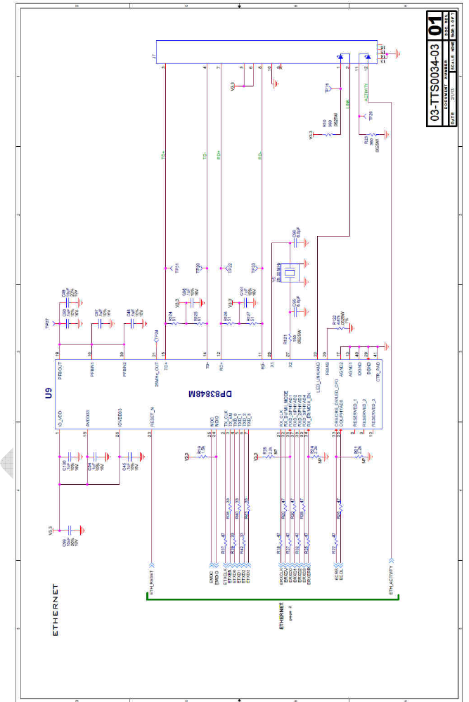
4.10.3 Ethernet
The device supports Ethernet 802.3 communication at 10/100 data-rates through an RJ45 connector and 802.11 via
Microchip
MRF24J40 transceiver. Not supported in first release. Somewhere in this document we need a
table of interfaces/features showing what will be supported by the firmware at launch. We should also
make clear that the interface is provided so the customer can add that functionality if desired. Make
sure to provide links to stacks and code examples that the customer can use to add the functionality.
4.11 SD Card Support
The device provides an optional connection for an SD card. The SD card be connected through a standard SD card
holder mounted onto the PC9 of the device. The SD card is readable and writable by the host processor
for writing
log files or storing measurement data or other purposes that a running application may need.
4.12 Sensing

4.12.1 Accelerometer
The device includes an accelerometer capable of measuring acceleration in three axes. The typical type of movement
which will be sensed is vibration. The
update rate is configurable by software
4.12.2Light Level
The device includes a photo-sensitive device which responds to the surrounding light level.
4.12.3 Temperature
The device includes an internal temperature sensor capable of measuring temperature within +/- 1 °C ov er the entire
operating temperature range.
The temp sensor is the Microchip MCP9800 an I2C interface with the lsb set
to 0.5°C…. Although temperatures are in Celsius, TT Web site supporting the M2M demo converts
temperature data into Fahrenheit.
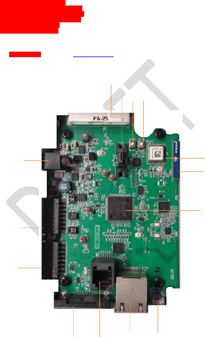
5.0 Hardware Description
Put photos of the device here.
Put board photo balloons/U# cross index table here?
5.1 Power and Bus Connectors
Balloon ID 1
Power Adaptor Input -
The power supply supports an input DC supply voltage between 6 and 12VDC.
Optionally, up to 24VDCinput may be supported. A switch controls the activation of power to the board.
•
Balloon ID TBD
5VDC out
Balloon ID TBD
Debugging/Programming Port - J9. Programming/debugging connector. Standard
Microchip connector for plugging into ICD3/Real ICE.
Balloon ID TBD Sensor Input Header – The processor provides 2 analog to digital converter connections to the
external header, 4 general purpose digital I/O connections, 1 SPI connection, 1 UART connection. One of the analog
to digital inputs can be configured to measure a 5 to 20mA current source through the placement or non-placement of
a component. There is a single power output which supplies 100mA of current at 5VDC and there is 1 ground
connection to the circuit board. In addition, the processor provides 1 PWM output on the external header.
Need Pin-out diagram for Sensor Input Header
5.2 Communication Devices
Balloon ID TBD CDMA Radio/GPS -
The cellular module certified for operation on the Verizon Wireless
cellular network.
Balloon ID TBD
Cellular Antenna
- The cellular antenna operates in the CDMA (869-894MHz) and PCS (1930-
1990MHz) bands.
Balloon ID TBD 802.15.4 - The 802.15.4 transceiver is able to transmit in ‘normal’ (250kbps) mode and ‘burst’ mode.
The burst mode data-rate supported is 500kbps. The transceiver provides a sleep mode with current draw less than

1mA. The transceiver communicates with the host processor through an SPI interface. The 802.15.4 antenna
operates in the 2.4GHz ISM band.
Balloon ID TBD Ethernet 802.3 - The Ethernet PHY operates at 10/100 data-rates and communicates with the MCU
Ethernet MAC through MII or RMII interface. Physical connectivity is via an RJ-45 adaptor.
J3. J7. Ethernet RJ45
connector. Standard Ethernet connector, with Link and Activity LEDs. 10/100Mbps Ethernet supported
by hardware.
Balloon ID TBD RS-232 - The device supports RS2:2 communication through a DB-9 connector.
J11. DB9 serial
port connector. Standard serial port connector for RS232, with optional support for hardware
handshake CTS/RTS lines.
Balloon ID TBD DB9 CAN - The CAN transceiver operates at speeds up to 1Mbps and conforms to the ISO 11898
standard. The hardware interface is a D9-9 connector.
Balloon ID TBD Micro USP
J12. DC Power jack with 2.5mm center; center is positive. Provides power for
the unit; nominally 12V DC, but accepts 7-16V. Power supply must provide at least 250mA @ 12V, but
500mA preferred.
Balloon ID TBD
J8. Micro USB receptacle. A standard Mirco USB receptacle, this connects directly to the
cell module, and is only used for evaluation and possible firmware update of the cell module. Generally
not used.
4.3 Board Memory
Balloon ID TBD SD Card - Accepts standard sized SD cards which supports up to 2GB flash cards. The SD card
interface communicates with the host processor through SPI.
J15. Micro SD card slot. Fits a standard micro SD
card. Note that the slot is on the bottom of the board, so when inserting micro SD card, it must be
“upside down” with the contacts facing up. Micro SD card is pushed in to insert, and pushed in again to
remove.
Balloon ID TBD 8MBit Flash Memory - The external flash communicates with the processor through SPI. This flash
memory supplies 512 KB of storage
which the devices uses for storing configuration information.
5.4 On-Board Sensors
Balloon ID TBD Temperature - The temperature sensor is able to measure temperature within +/- 1°C over the entire
operating temperature range of the device.
Balloon ID TBD Light -
The light sensor produces an analog voltage between 0 and 3V proportional to the light
intensity incident on the sensor.
Balloon ID TBD Accelerometer - The accelerometer is able to measure acceleration in three perpendicular axes and
is capable of measuring accelerations between 0 and 8g’s with a 10 bit resolution. It is capable of supplying a sample
rate of 200Hz. The accelerometer can be configured to provide the host processor with a wakeup signal when the
acceleration exceeds a pre-programmed limit. The accelerometer communicates with the host processor through
SPI.
5.5 User Interface
• Balloon ID TBD Power LED
• Balloon ID TBD Cellular Signal LED
• Balloon ID TBD Cellular Activity LED
• Balloon ID TBD Zigbee Status LED
• Balloon ID TBD Button 1
• Balloon ID TBD Button2
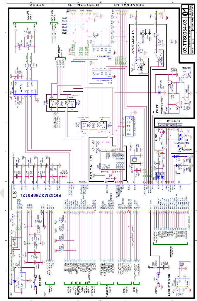
5.6 PIC 32 Processor
• Balloon ID TBD MCU32 model PIC32MX795F512L contains 512 KB flash memory, 128 KB RAM, 32 Bit 80
Mhz Processor.

This picture is rev2 It needs to be replaced with Rev3
6.0 Getting Started
6.1 Signup
6.1.1 Obtaining the Boards MEID Number
1. The MEID value is
printed on the sticker on the side or bottom of the platform, is is also
printed to
the serial port upon power up. Attach a serial cable to the DB9 RS-232 connector of your M2M device and
the other end to a serial port on another computer running a terminal emulation program. Configure your
terminal emulation program to operate at 115200 baud, No parity, No flow control, 8 bits per character and 1
stop bit.
2. Inert a power cable into the D/C power adaptor located on the side of the unit.
3. Once power is applied the board begins transmitting health and status data to the serial port, boot progress
and sensor information. Near the beginning of this output is a line similar to:
01/01/13 00:00:02.537 <Cell > MEID = 0xA1000013F617DF
6.1.2 Purchase a Verizon Data Plan
Before you can run your board, you will need to first purchase a data plan from Verizon.
1. Go to Verizon and purchase plan.
When they buy the device from MCHP Direct, the information they provide will be sent to TT. They
will receive an email within one business day with instructions for purchasing a data plan, activating
the device, and logging into the portal. Need to work with TT to make this as quick and painless as
possible.
6.1.3 Register With Twist M22 Developer Web Site
1. To capture your sensor data within the TwistThink TT database (see Fundamental Description for
explanation), you must first register the MEID with the M2M web server located at
http://ttm2m.spindance.net. Enter your MEID (minus the leading 0x), a password and then click “New
Account” button
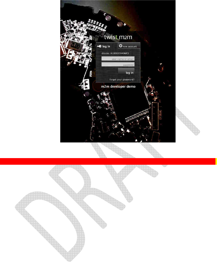
These are old pcs
The web portal is being modified per Marketing. You will need new screen caps.
6.2 Interacting with the Web Site
The M2M Developers web site is specifically tailored to work with the example code programmed into
your M2M board.
6.2.1 Device Tab
The device page is the first page that you are taken to when you successfully log into the m2m
developer demo web site. If your device is active when you log into the web site, you should see the
“data in/out” status indicator in the upper right hand corner as highlighted indicating that the m2m
developer web server is receiving data from your device over the cellular phone system.
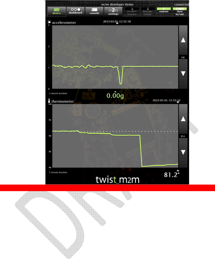
These are old pcs
The web portal is being modified per Marketing. You will need new screen caps.
The device page graphically depicts the sensor status for the accelerometer in g’s and the thermometer
in degrees Each graph has a movable trend line that you can move using the arrows provided on the side
margin of each graph.
6.2.2 Dashboard Tab
sdfsdf
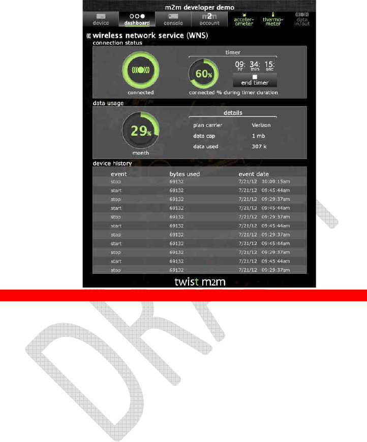
These are old pcs
The web portal is being modified per Marketing. You will need new screen caps.
6.2.3Console Tab
sdfsdf

6.2.4 Account Tab
sdfsdf
6.2.5 Accelerometer Tab
sdfsdf
6.2.6 Thermometer Tab
sdfsdf
7.0 Software API
Include SW block diagram and short description of each block as a lead-in to the API. Just document the
DCF API in detail. Refer to the FreeRTOS site for FreeRTOS API documentation. Refer to MCHP site for
stack and plib documentation.

Appendix A Compiling the Project
A.1 Connecting the Real-ICE
– The M2M board has a RJ-11 receptacle that is used for downloading
binary images and for debugging. The M2M board is designed to be used with Microchips MPLAB REAL ICE
debugger/programmer. To connect the REAL ICE to the M2M board, remove the M2M top cover to expose the RJ-11
receptacle mounted inside. Attach the REAL-ICE RJ11 telephone cable into the M2M’s RJ-11. Attach one end of a
USB cable to your REAL ICE and the other end into your PC.
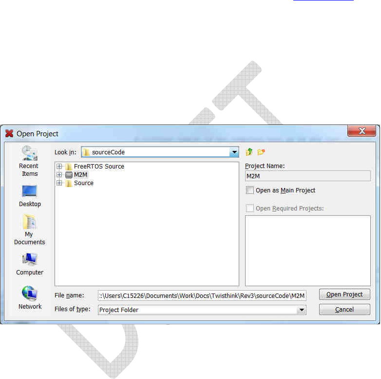
A.1 Opening the Project
MPLAB is Microchips integrated development solution used to develop, program and debug your M2M device. Plug
an external 12v 0.5 Amp power supply into the M2M barrel adapter to power-on the M2M device. Start the MPLAB
IDE and open the File menu option and select Open Project. Using the Open Project dialog box shown below
navigate to the directory that contains the M2M project as shown below. Once you select the project and press the
Open Project button on the lower right hand corner of the dialog box, the IDE will begin loading and parsing the
project.
A.3 Making the Project and Programming the Board
1. At this point the MPLAB main window title bar should contain the name of the M2M project.
2. Be sure that the M2M project is the active project by right clicking on its name within the project window
pane.
3. From the pop menu that shows-up select “Set as Main Project”.
4. Be sure that the project is configured to work with the REAL-ICE by right clicking on its name within the
project window pane and selecting Properties to bring up the Project Properties dialog box shown below.
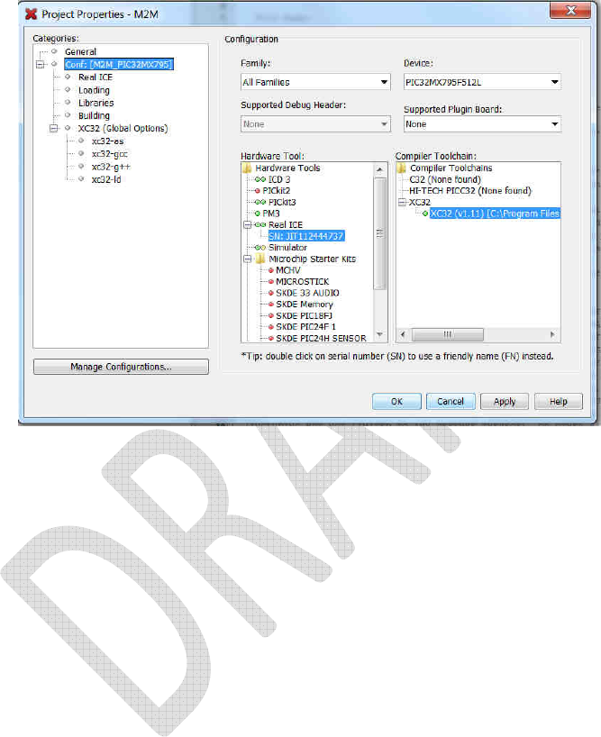
5. Be sure that the Real ICE SN: ######## is selected and press apply.
6. Be sure that the Device in Project Properties is set as PIC32MX795F512L
7. Click Apply to accept the changes if any. Then press OK to close the dialog box.
8. Near the top there is an icon button much like the one shown below. Press the small arrow on the side of the
button to expose the attached menu. Select Make and Program Device Main Project to rebuild outdated
file, program the device and start a debug session.
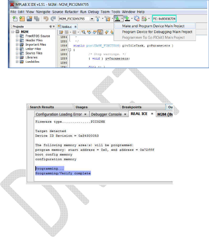
Making and programming the project
The above picture shows message indicating the board has been programmed and is now running.

Appendix B Board Schematics
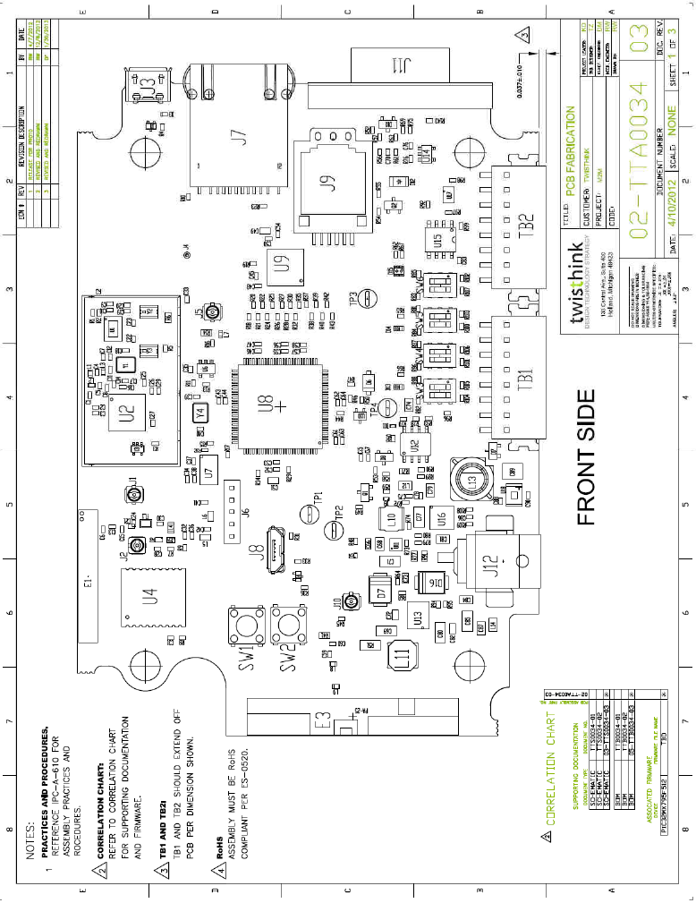
B.1
B.2
B.3
B.4
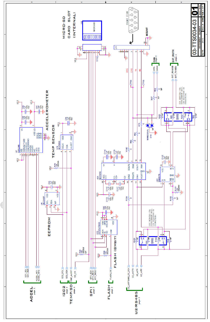
B.5
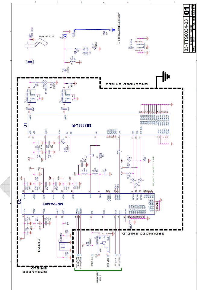
B.6
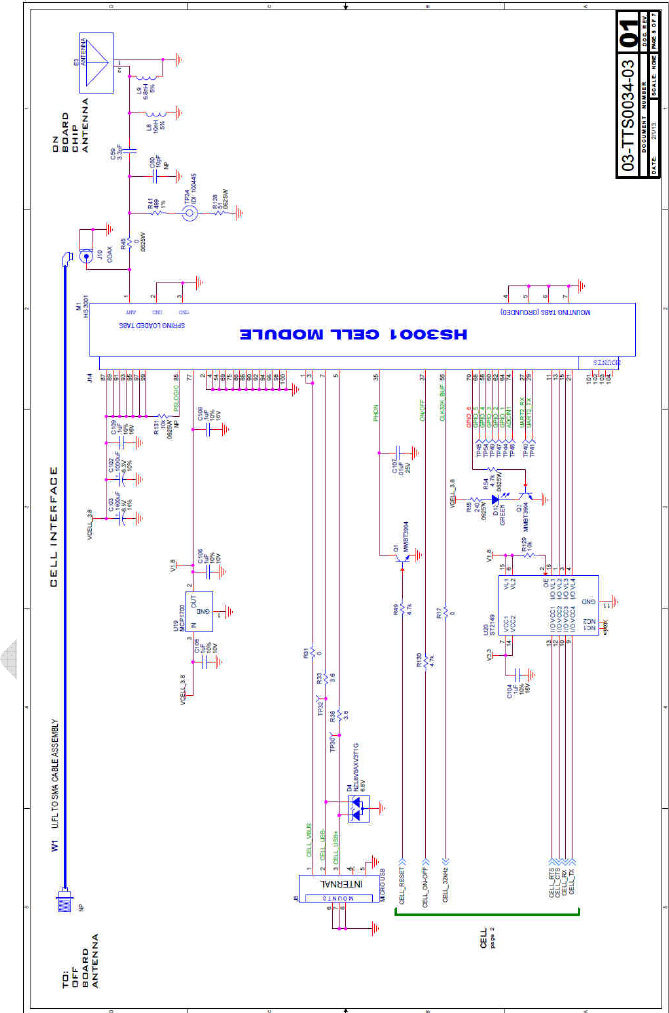
B.7
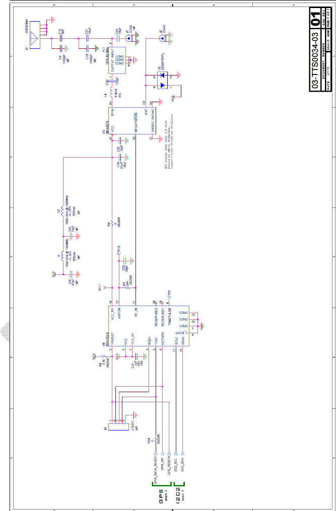
B.8