Two Technologies JETTRFID-1356 JETT® RFID Reader User Manual JETT RFID Technical Reference Manual
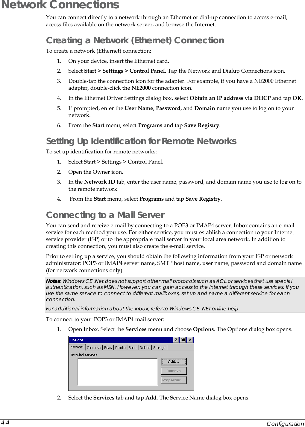
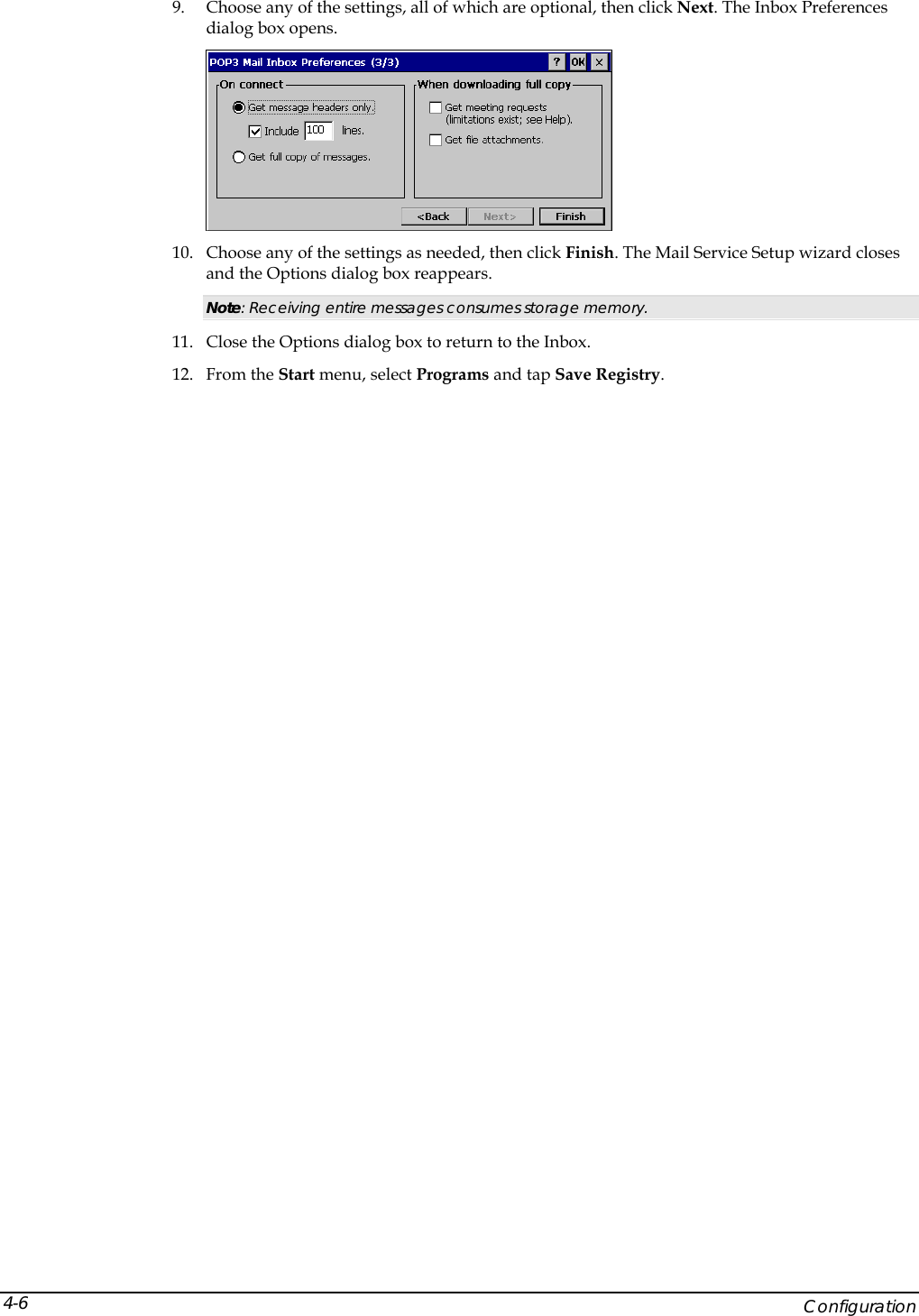
Two Technologies, Inc. JETT® RFID Reader JETT RFID Technical Reference Manual
UserManual.wiki
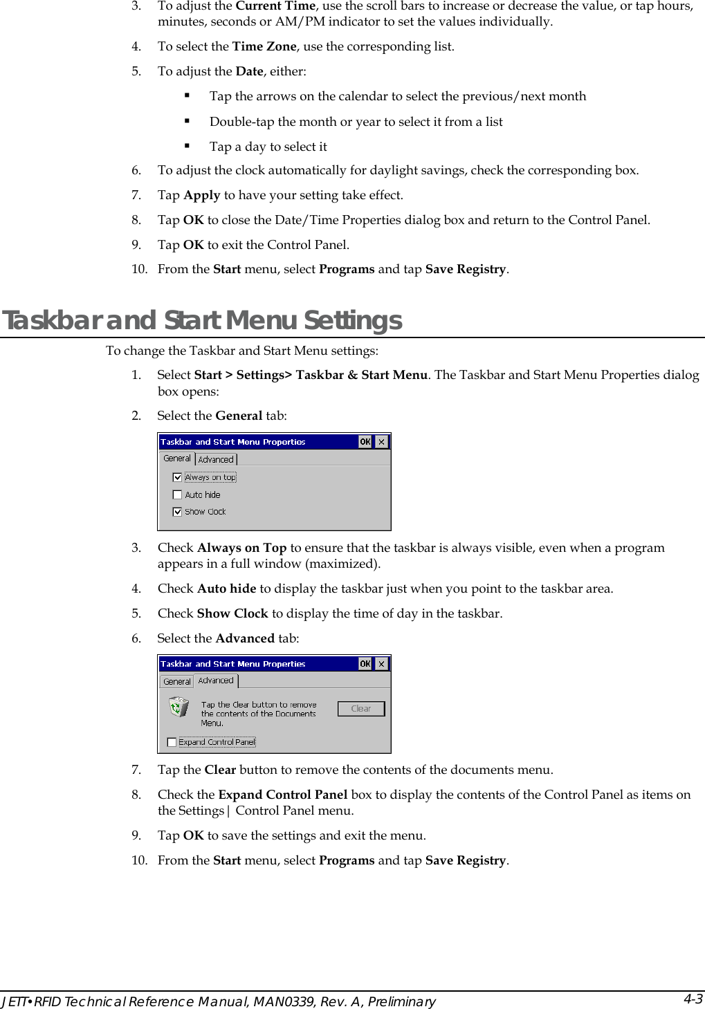
>
Two Technologies
>
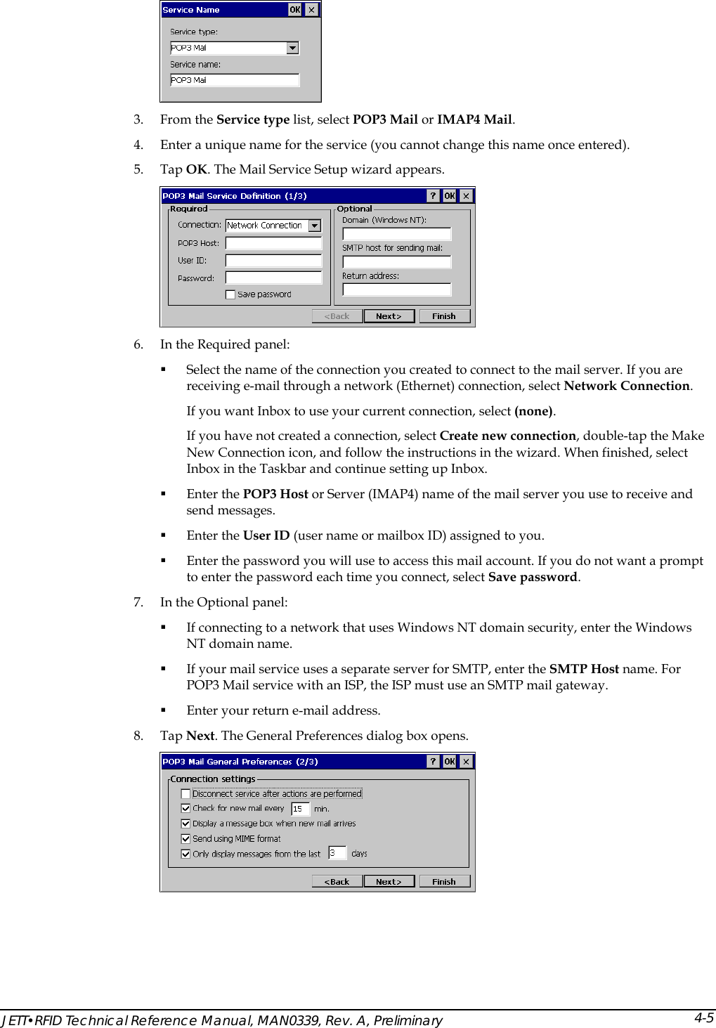
JETTRFID 1356 User Manual
Users Manual
Navigation menu
Upload a User Manual
Namespaces
Wiki Guide
HTML
PDF
Info
Views
User Manual
Discussion / Help
Navigation

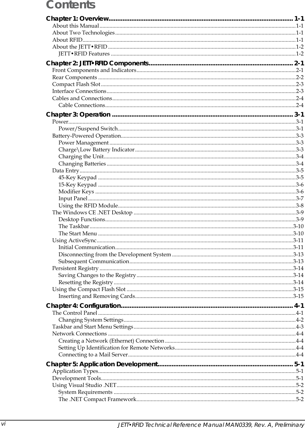
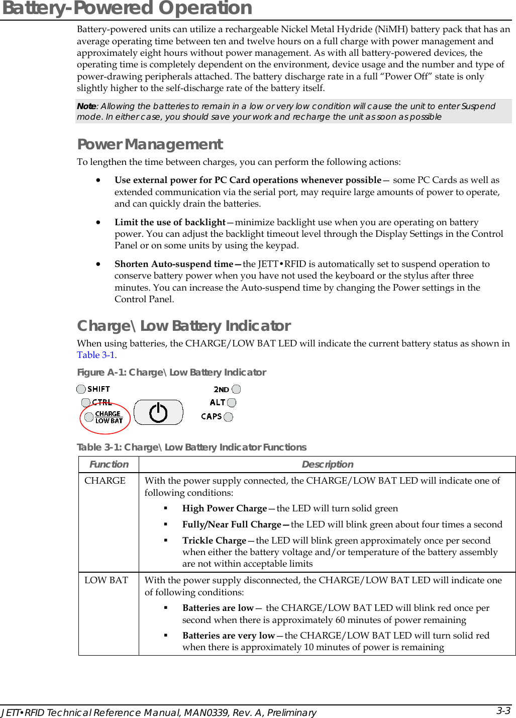
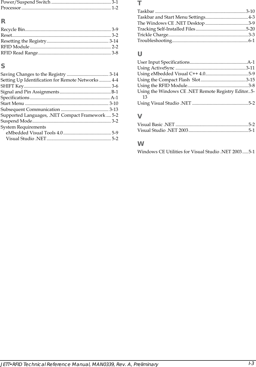
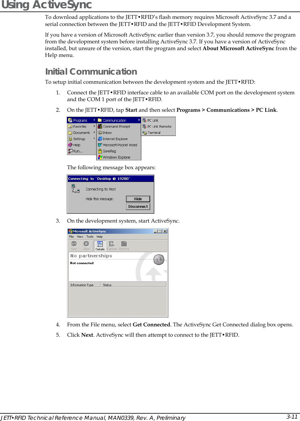
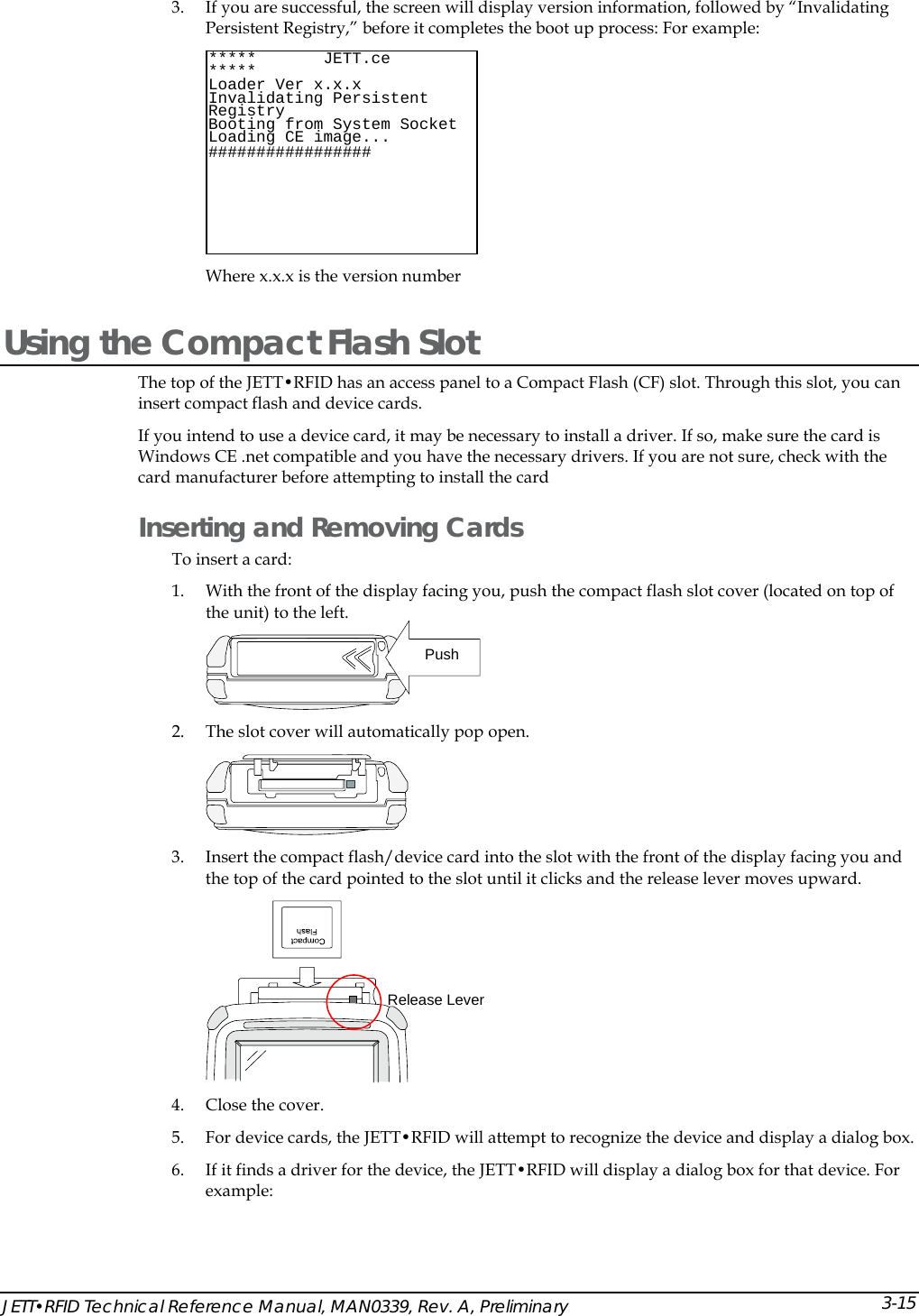
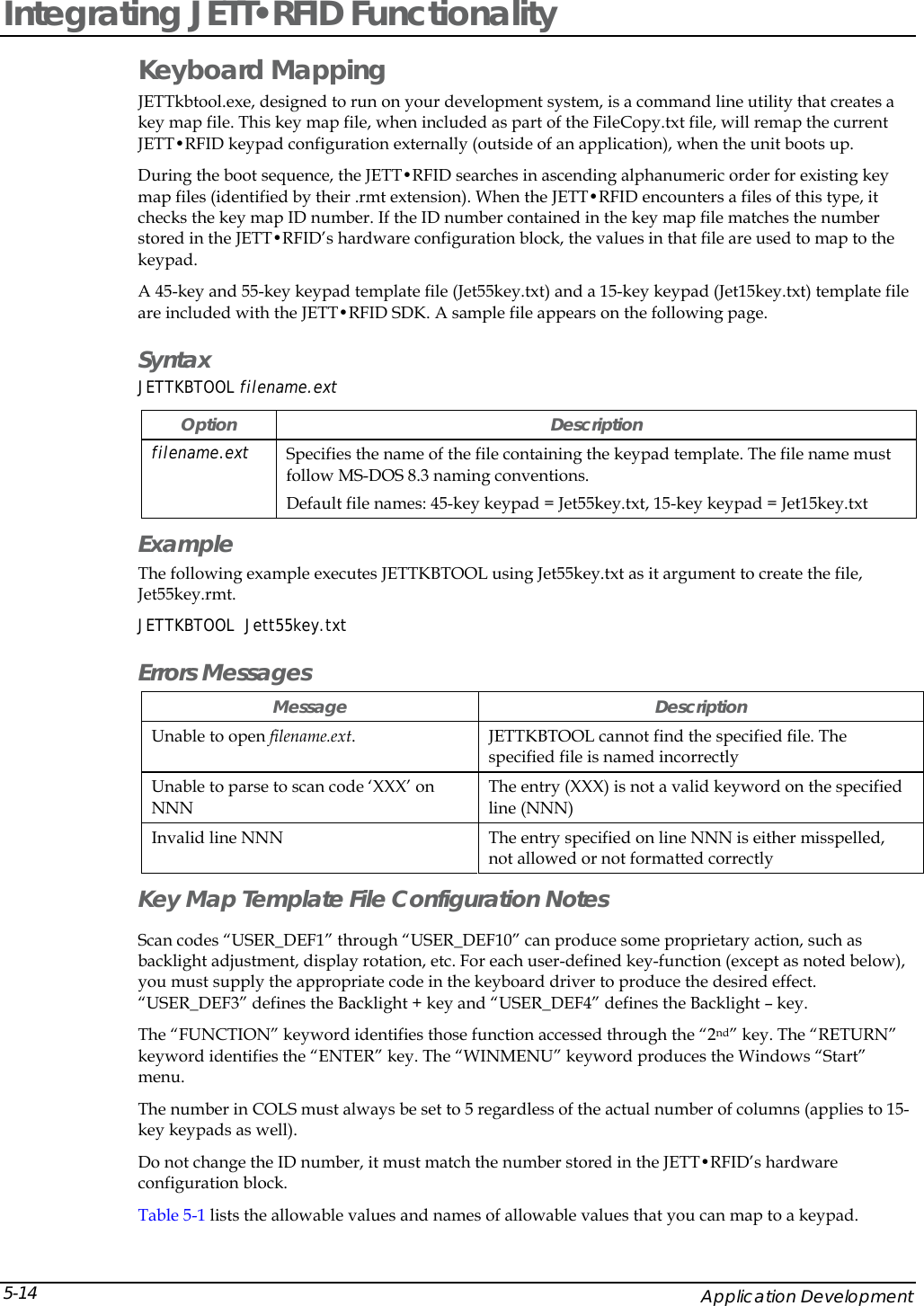
![Figure A-2: Battery Orientation 5. Close the battery cover and turn the battery cover retaining clip clockwise to lock the cover. Data Entry 45-Key Keypad In order to provide the functionality of a full-sized keyboard with only 45 keys, the JETT•RFID keypad must depart from PC-style key assignment conventions. Units configured with the standard 45-key keypad typically utilize five LED indicators (located above the ON/OFF switch) to indicate the active state of keypad modifier keys. Units with internal batteries also use a LED to indicate the battery status (Table 3-1). Units with 45-key keypads also have keypad functions to adjust the contrast and backlight. Figure A-1: 45-Key Keypad GADelete BPgUp CPgDn DInsertE FHome HI{J~KL}<END _>^Pause(!;)[?']RST#Q&@$U+V,/XBKLT +-W=Y%7F79F98F8Z*4F46F65F5.\1F12F23F30F10BACKSPACE SPACE ENTERSHIFT 2ND CTRL ALT ESCBKLT -"ClearOMN PTab Tab,WMENUF11F12| JETT•RFID Technical Reference Manual, MAN0339, Rev. A, Preliminary 3-5](https://usermanual.wiki/Two-Technologies/JETTRFID-1356/User-Guide-414248-Page-23.png)
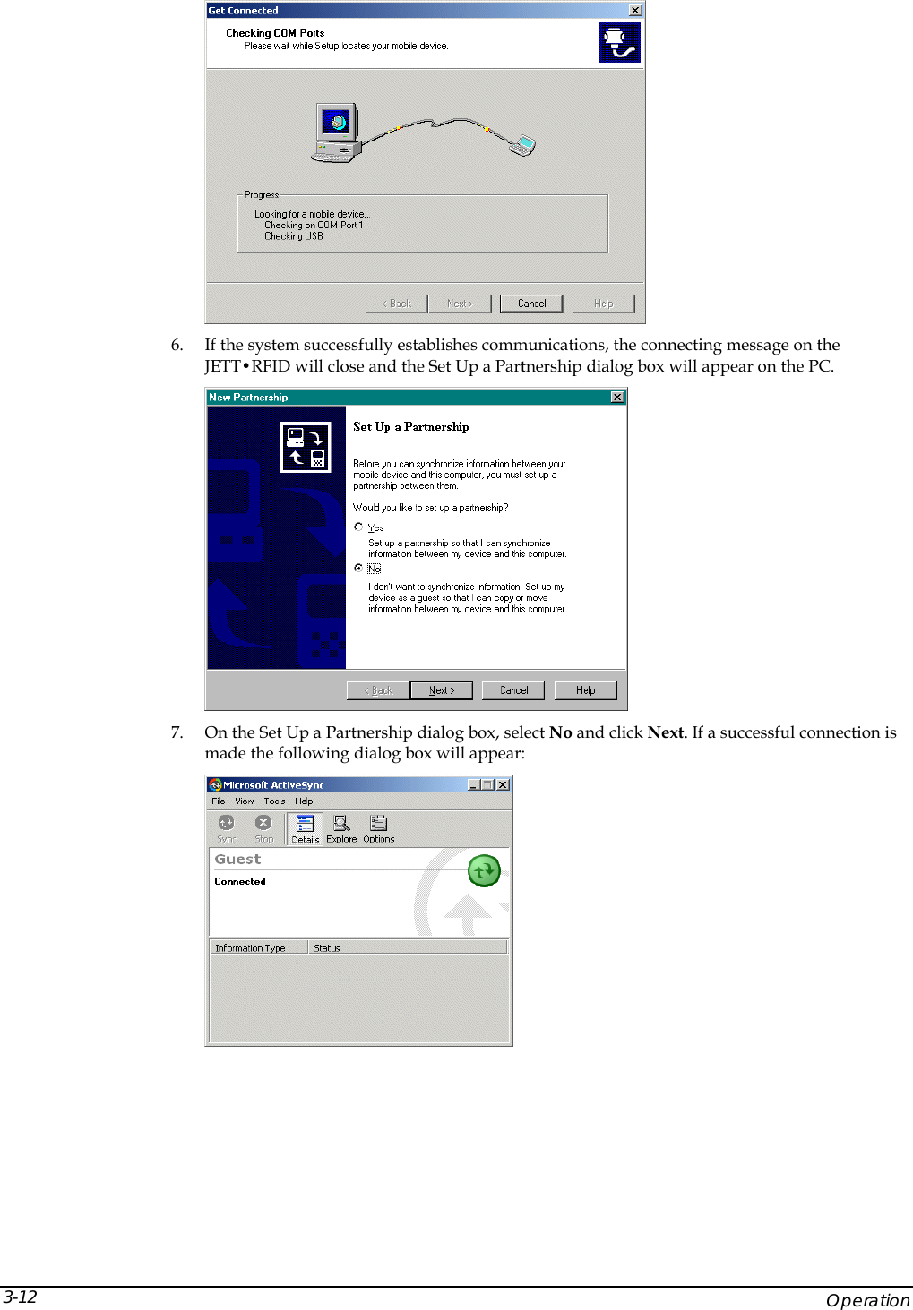
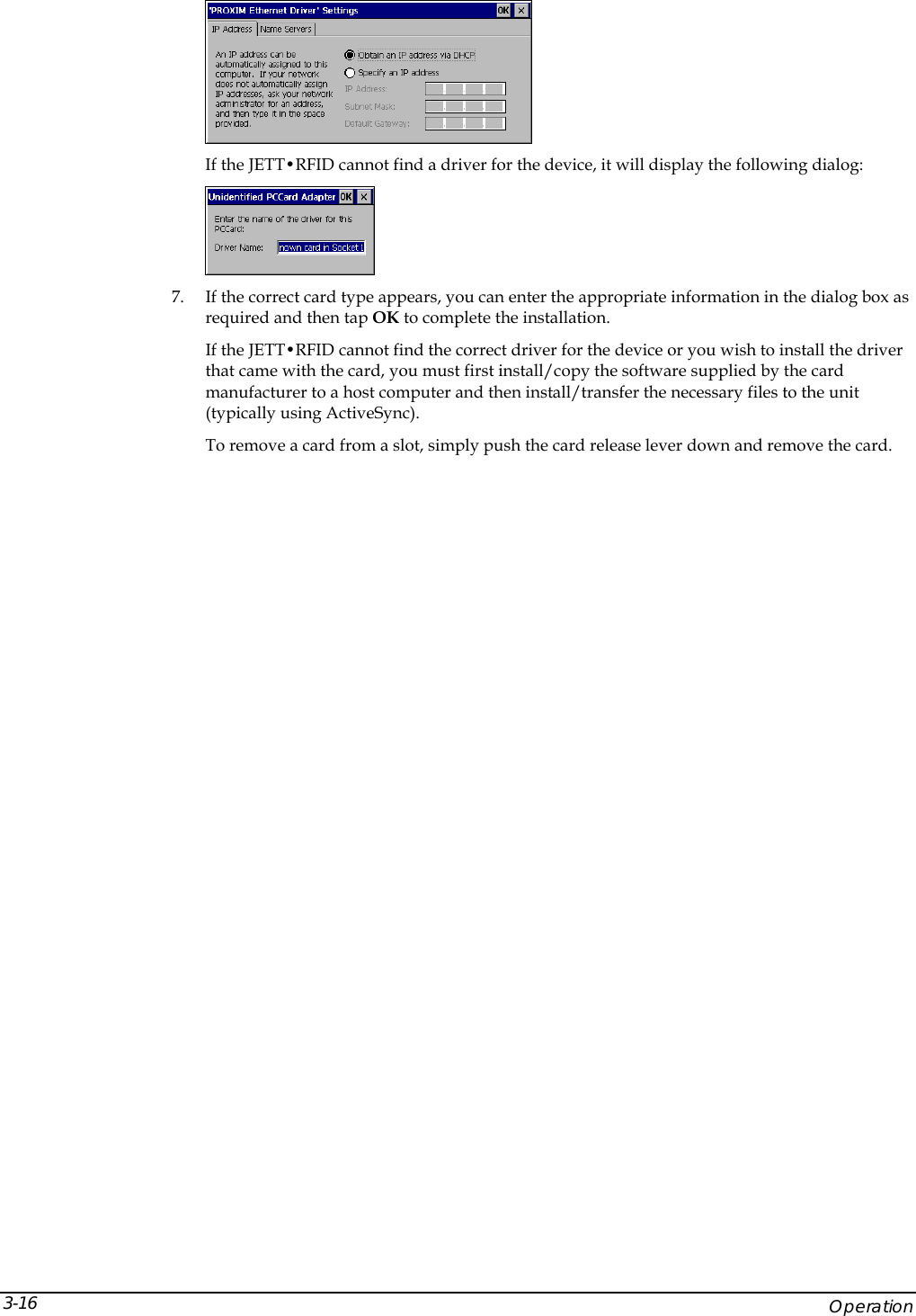

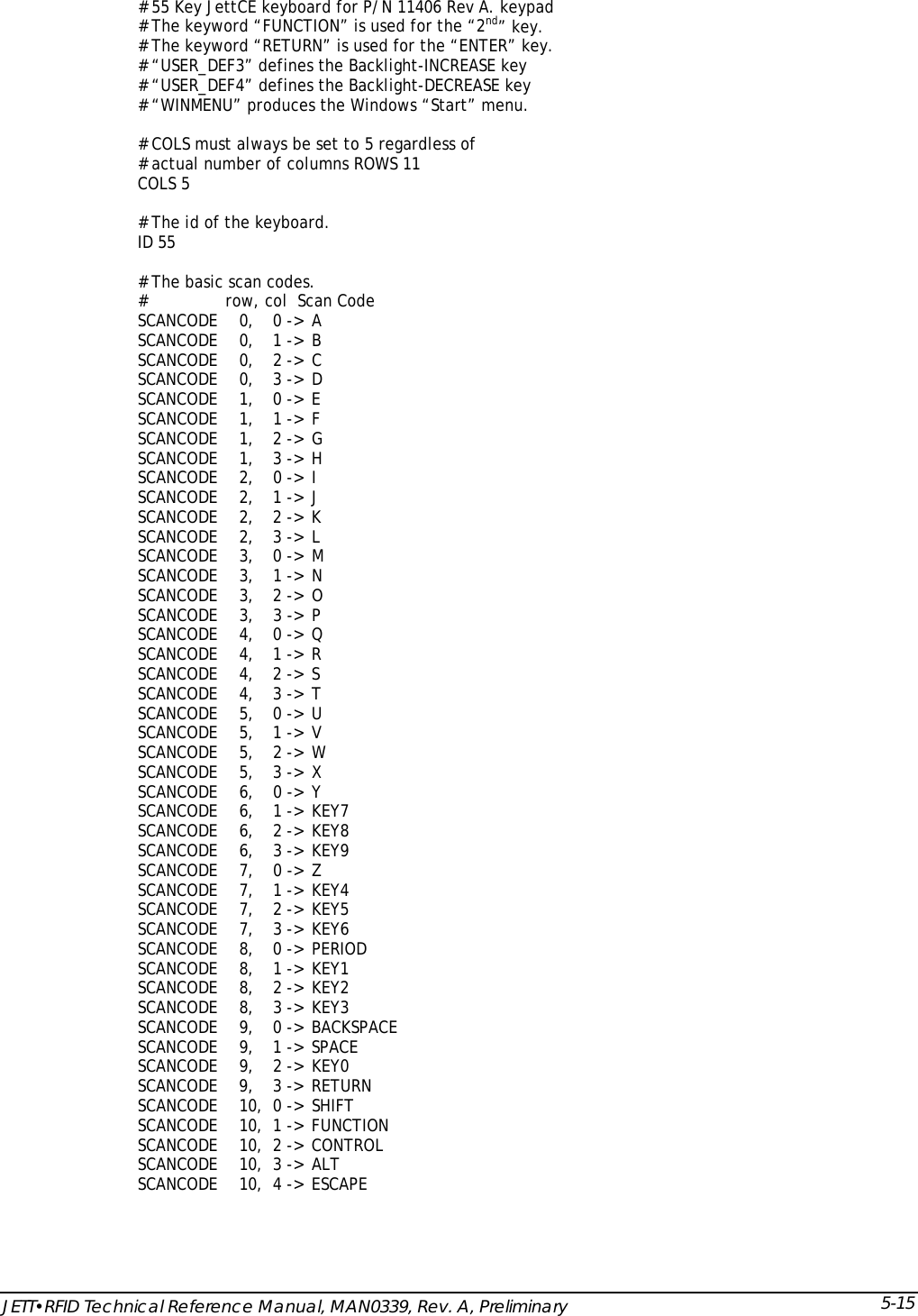
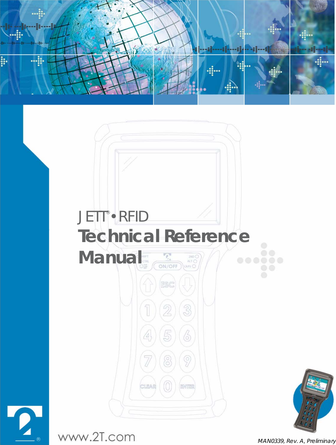
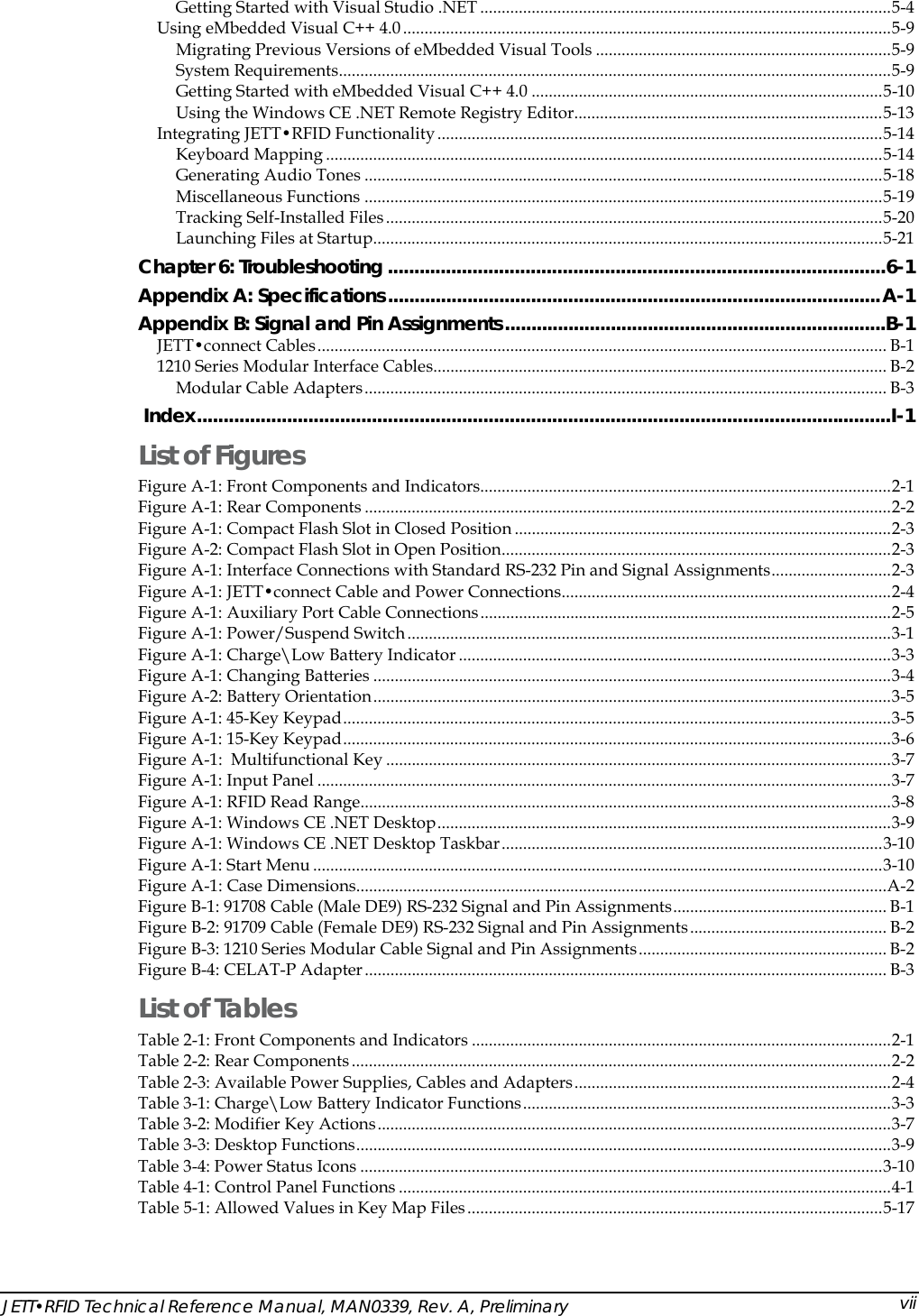
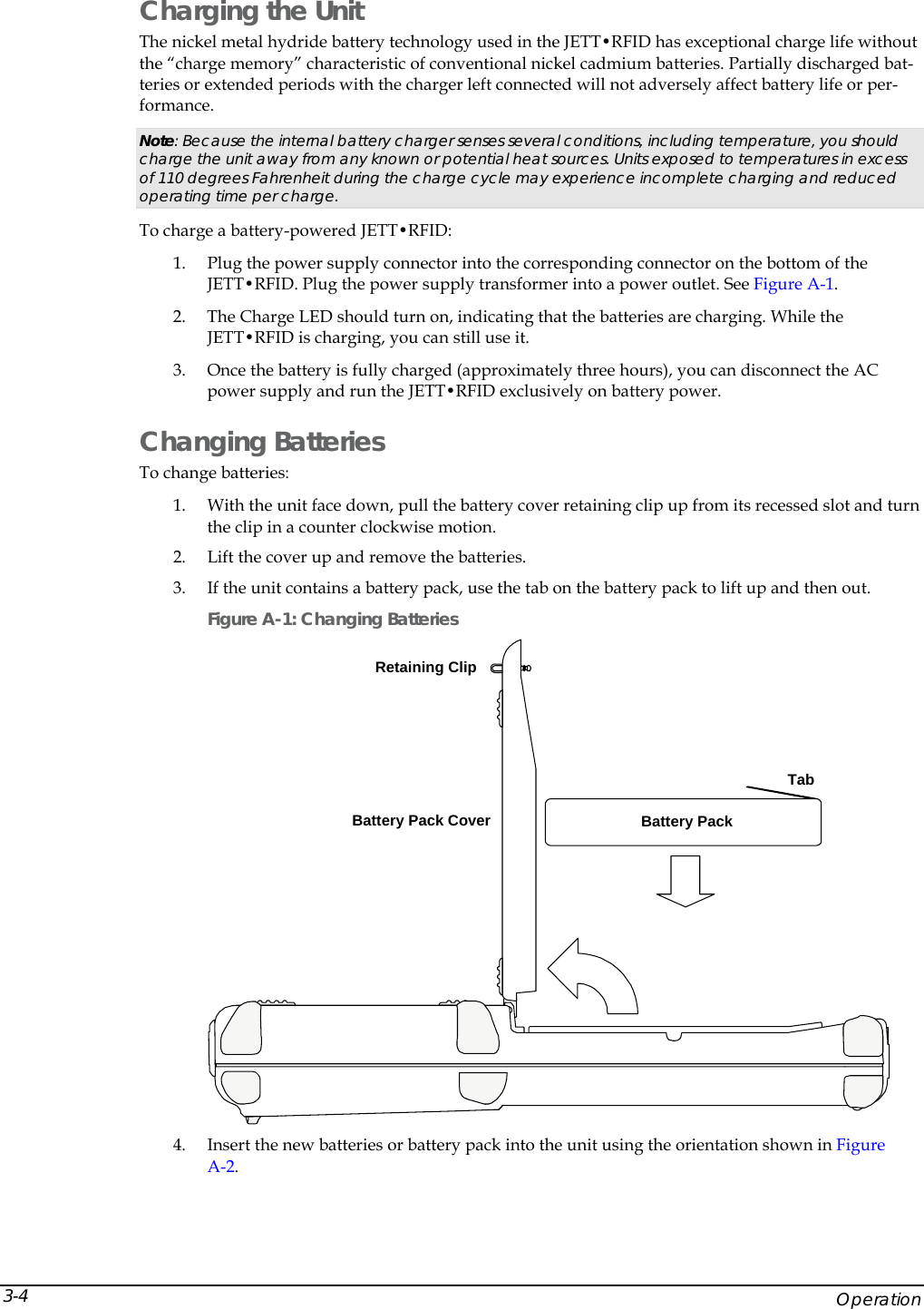
![# Table 0 is always the unshifted values. TABLE 0, basic, UNSHIFTED TABLE 1, func, FUNCTION TABLE 2, shift, SHIFT # Func remapping table. REMAPPING func, A -> DELETE REMAPPING func, B -> PAGEUP REMAPPING func, C -> PAGEDOWN REMAPPING func, D -> INSERT REMAPPING func, E -> CAPSLOCK REMAPPING func, F -> HOME REMAPPING func, G -> CLEAR REMAPPING func, H -> SCROLL REMAPPING func, I -> { REMAPPING func, J -> TILDA REMAPPING func, K -> PAUSE REMAPPING func, L -> } REMAPPING func, M -> BACKTAB REMAPPING func, N -> CARET REMAPPING func, O -> COLON REMAPPING func, P -> TAB REMAPPING func, Q -> USER_DEF2 REMAPPING func, R -> PIPE REMAPPING func, S -> HASH REMAPPING func, T -> USER_DEF1 REMAPPING func, U -> USER_DEF4 REMAPPING func, V -> COMMA REMAPPING func, W -> TILDA REMAPPING func, X -> USER_DEF3 REMAPPING func, Y -> F11 REMAPPING func, Z -> F12 REMAPPING func, PERIOD -> BACKSLASH REMAPPING func, KEY7 -> F7 REMAPPING func, KEY8 -> F8 REMAPPING func, KEY9 -> F9 REMAPPING func, KEY4 -> F4 REMAPPING func, KEY5 -> F5 REMAPPING func, KEY6 -> F6 REMAPPING func, KEY1 -> F1 REMAPPING func, KEY2 -> F2 REMAPPING func, KEY3 -> F3 REMAPPING func, KEY0 -> F10 # Shift remapping table. REMAPPING shift, A -> LEFT REMAPPING shift, B -> UP REMAPPING shift, C -> DOWN REMAPPING shift, D -> RIGHT REMAPPING shift, E -> < REMAPPING shift, F -> END REMAPPING shift, G -> UNDERLINE REMAPPING shift, H -> > REMAPPING shift, I -> ( REMAPPING shift, J -> EXCLAMATION REMAPPING shift, K -> SEMICOLON REMAPPING shift, L -> ) REMAPPING shift, M -> [ REMAPPING shift, N -> QUESTION REMAPPING shift, O -> QUOTE REMAPPING shift, P -> ] REMAPPING shift, Q -> AMPERSAND REMAPPING shift, R -> AT Application Development 5-16](https://usermanual.wiki/Two-Technologies/JETTRFID-1356/User-Guide-414248-Page-56.png)
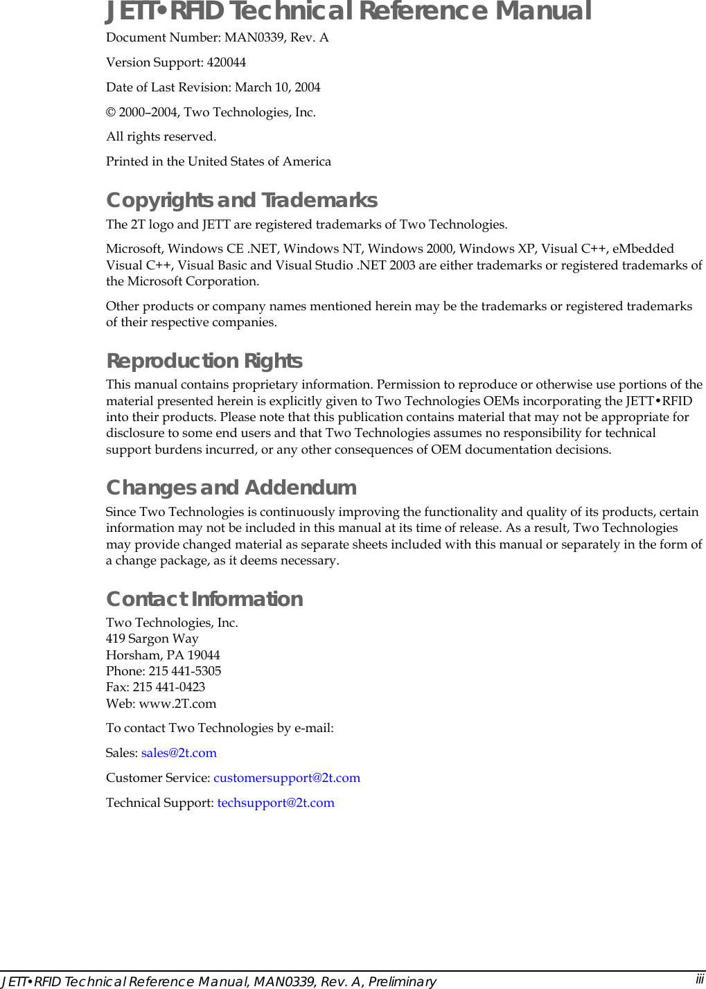
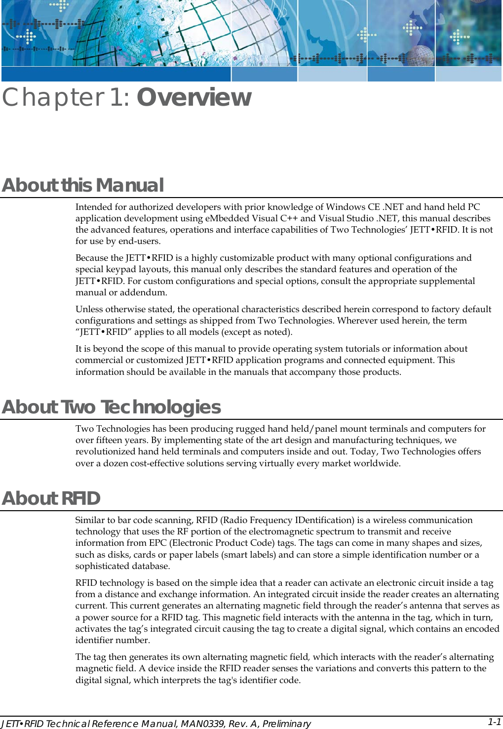
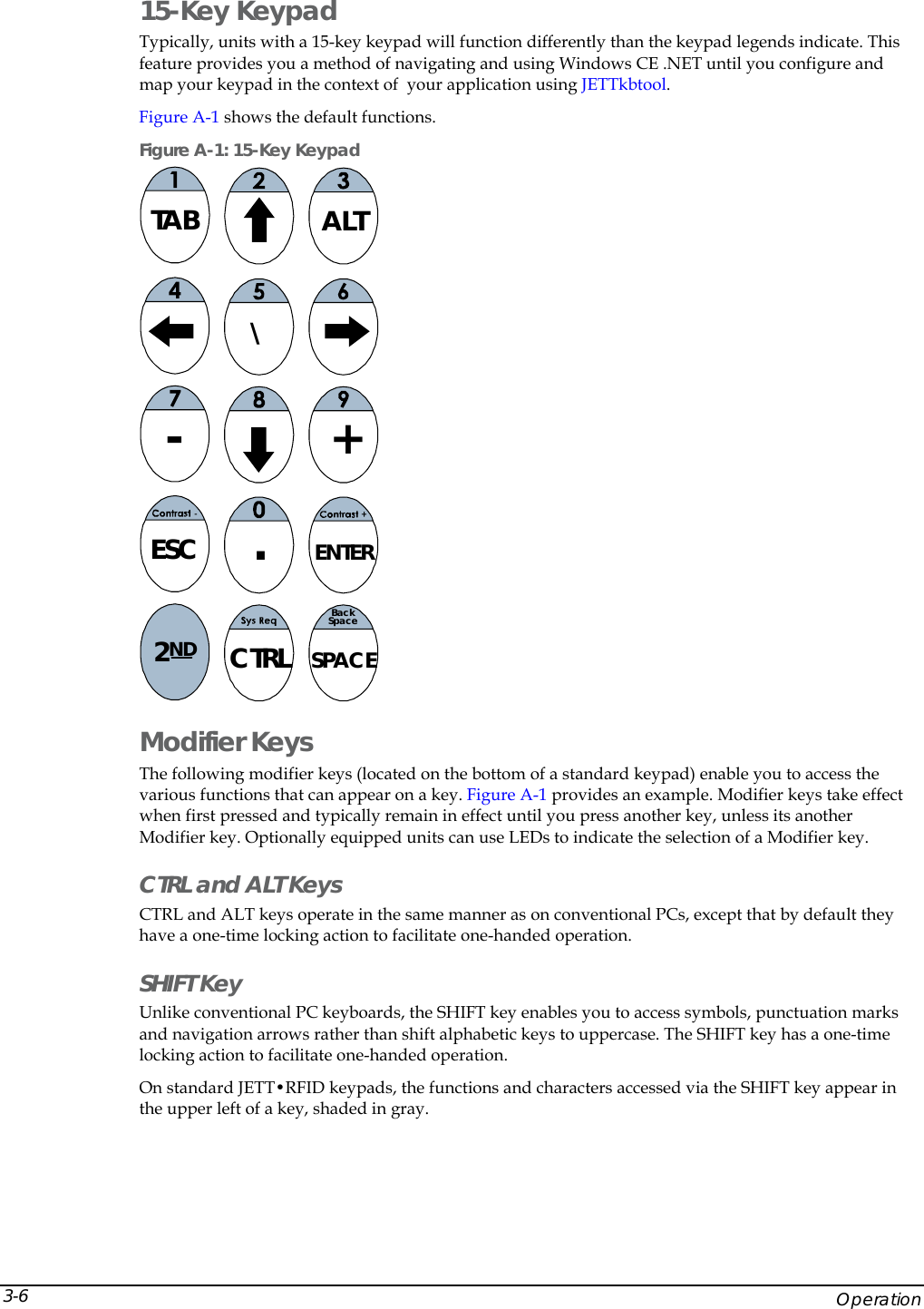
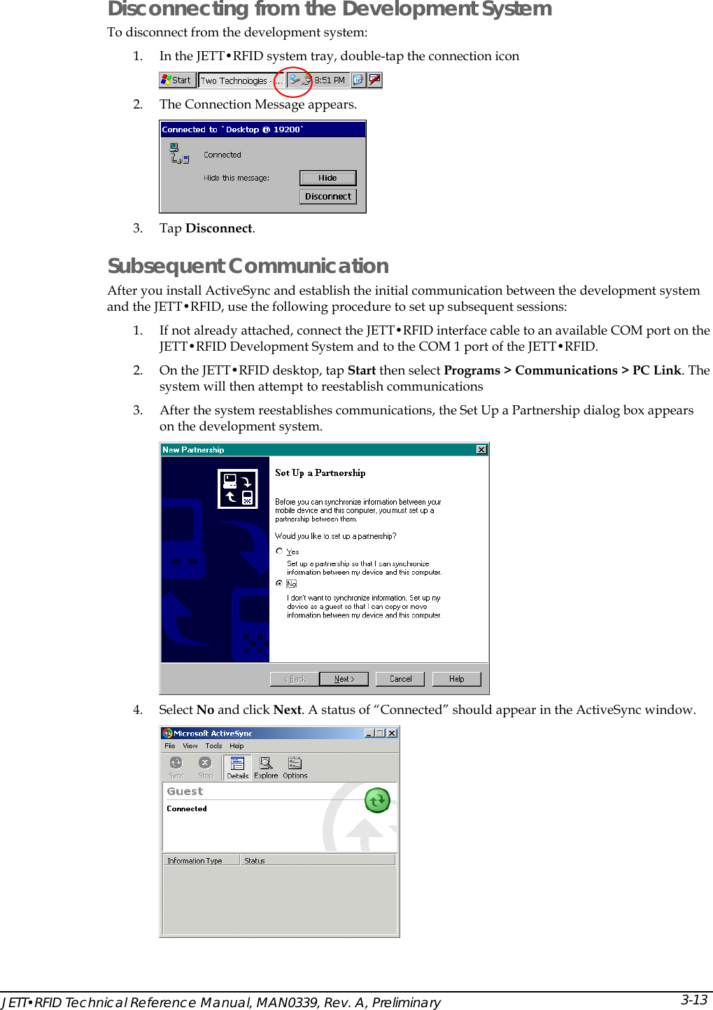
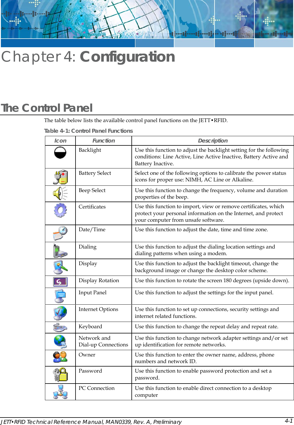
![REMAPPING shift, S -> HASH REMAPPING shift, T -> DOLLAR REMAPPING shift, U -> SUBTRACT REMAPPING shift, V -> SLASH REMAPPING shift, W -> EQUAL REMAPPING shift, X -> ADD REMAPPING shift, Y -> PERCENT REMAPPING shift, Z -> STAR REMAPPING shift, PERIOD -> DOUBLEQUOTE #REMAPPING shift, KEY7 -> #REMAPPING shift, KEY8 -> #REMAPPING shift, KEY9 -> #REMAPPING shift, KEY4 -> #REMAPPING shift, KEY5 -> #REMAPPING shift, KEY6 -> #REMAPPING shift, KEY1 -> #REMAPPING shift, KEY2 -> #REMAPPING shift, KEY3 -> #REMAPPING shift, KEY0 -> Table 5-1: Allowed Values in Key Map Files A V CARET F9 NUMPAD1 SEMICOLON B W CLEAR F10 NUMPAD2 SHIFT C X COLON F11 NUMPAD3 SLASH D Y COMMA F12 NUMPAD4 SPACE E Z CONTROL FUNCTION NUMPAD5 STAR F ( DELETE HASH NUMPAD6 SUBTRACT G ) DOLLAR HOME NUMPAD7 TAB H [ DOUBLEQUOTE INSERT NUMPAD8 TILDA I ] DOWN LEFT NUMPAD9 UNDERLINE J { END KEY0 PAGEDOWN UP K } EQUAL KEY1 PAGEUP USER_DEF1 L < ESCAPE KEY2 PAUSE USER_DEF2 M > EXCLAMATION KEY3 PERCENT USER_DEF3 N ADD F1 KEY4 PERIOD USER_DEF4 O ALT F2 KEY5 PIPE USER_DEF5 P AMPERSAND F3 KEY6 PRINT USER_DEF6 Q AT F4 KEY7 QUESTION USER_DEF7 R BACKQUOTE F5 KEY8 QUOTE USER_DEF8 S BACKSLASH F6 KEY9 RETURN USER_DEF9 T BACKSPACE F7 NUMLOCK RIGHT USER_DEF10 U CAPSLOCK F8 NUMPAD0 SCROLL WINMENU JETT•RFID Technical Reference Manual, MAN0339, Rev. A, Preliminary 5-17](https://usermanual.wiki/Two-Technologies/JETTRFID-1356/User-Guide-414248-Page-57.png)