Two Technologies JETTRFID-1356 JETT® RFID Reader User Manual JETT RFID Technical Reference Manual
Two Technologies, Inc. JETT® RFID Reader JETT RFID Technical Reference Manual
Users Manual

JETT®•RFID
Technical Reference
Manual
MAN0339, Rev. A, Preliminary

JETT•RFID Technical Reference Manual
Document Number: MAN0339, Rev. A
Version Support: 420044
Date of Last Revision: March 10, 2004
© 2000–2004, Two Technologies, Inc.
All rights reserved.
Printed in the United States of America
Copyrights and Trademarks
The 2T logo and JETT are registered trademarks of Two Technologies.
Microsoft, Windows CE .NET, Windows NT, Windows 2000, Windows XP, Visual C++, eMbedded
Visual C++, Visual Basic and Visual Studio .NET 2003 are either trademarks or registered trademarks of
the Microsoft Corporation.
Other products or company names mentioned herein may be the trademarks or registered trademarks
of their respective companies.
Reproduction Rights
This manual contains proprietary information. Permission to reproduce or otherwise use portions of the
material presented herein is explicitly given to Two Technologies OEMs incorporating the JETT•RFID
into their products. Please note that this publication contains material that may not be appropriate for
disclosure to some end users and that Two Technologies assumes no responsibility for technical
support burdens incurred, or any other consequences of OEM documentation decisions.
Changes and Addendum
Since Two Technologies is continuously improving the functionality and quality of its products, certain
information may not be included in this manual at its time of release. As a result, Two Technologies
may provide changed material as separate sheets included with this manual or separately in the form of
a change package, as it deems necessary.
Contact Information
Two Technologies, Inc.
419 Sargon Way
Horsham, PA 19044
Phone: 215 441-5305
Fax: 215 441-0423
Web: www.2T.com
To contact Two Technologies by e-mail:
Sales: sales@2t.com
Customer Service: customersupport@2t.com
Technical Support: techsupport@2t.com
JETT•RFID Technical Reference Manual, MAN0339, Rev. A, Preliminary iii

Warranty Information
Seller warrants that the product specified in this agreement is free of defects in materials and
workmanship, and shall conform to the latest specifications published prior to Buyer’s acceptance of the
agreement for a period of two years.
Product specifications as defined supersede previous specifications and are complete. Any parameter
that is not specifically defined in the specifications is expressly excluded from the warranty. This
warranty does not apply to any product which has been subject to misuse, accident, alteration, or if the
unit has been serviced by anyone other than an authorized representative of Seller.
Seller’s sole obligation to Buyer for products failing to meet specifications shall be, at Seller’s discretion,
to repair or replace the non-conforming device.
After receiving a Return Material Authorization (RMA) number and a mailing address from Seller, a
defective unit covered under this warranty may be returned freight prepaid. Any replacement or
repaired product shall carry only the unexpired term of the warranty plus any period required for
repair.
If Buyer has been expressly designated as an Original Equipment Manufacturer (OEM) by Seller, the
warranty period shall commence upon the earlier date of (i) delivery to Buyer’s first customer, or (ii)
180 days from the original date of shipment by Seller. In the events that products for which: (a) Buyer
has title and, (b) have never been used, and (c) have been in the Buyer’s possession for more than 180
days and, (d) have an unaltered date code attached, may for an established fixed fee which will not
exceed ten percent (10%) of the original purchase price, have the date code updated by the Seller and
thereby reestablish those products with a new warranty.
THE FOREGOING WARRANTY AND REMEDIES ARE EXCLUSIVE AND ARE MADE EXPRESSLY
IN LIEU OF ALL OTHER WARRANTIES EXPRESSED OR IMPLIED, EITHER IN FACT OR BY
OPERATION OF LAW, STATUTORY OR OTHERWISE, INCLUDING WARRANTIES OR
MERCHANTABILITY AND FITNESS FOR USE. TWO TECHNOLOGIES NEITHER ASSUMES NOR
AUTHORIZES ANY OTHER PERSON TO ASSUME FOR IT ANY OTHER LIABILITY IN
CONNECTION WITH THE SALE, INSTALLATION OR USE OF ITS PRODUCTS AND TWO
TECHNOLOGIES MAKES NO WARRANTY WHATSOEVER FOR PRODUCTS NOT
MANUFACTURED BY TWO TECHNOLOGIES.
TWO TECHNOLOGIES SHALL NOT BE LIABLE FOR DAMAGES DUE TO DELAYS IN DELIVERIES
OR USE AND SHALL IN NO EVENT BE LIABLE FOR INCIDENTAL OR CONSEQUENTIAL
DAMAGES OF ANY KIND, WHETHER ARISING FROM CONTRACT, TORT OR NEGLIGENCE,
INCLUDING, BUT NOT LIMITED TO, LOSS OF PROFITS, LOSS OF GOODWILL, OVERHEAD OR
OTHER LIKE DAMAGES.
To maintain your warranty and to avoid creating hazards, only qualified personnel should perform
authorized modifications to Two Technologies’ products. Two Technologies cannot assume
responsibility for any condition affecting the proper operation of this equipment that may result from
unauthorized modifications.
Product Returns
If, after inspection, you note any product damage or discrepancies, please contact us promptly within
five days of receipt. If the exterior of the package shows obvious signs of damage, please contact your
carrier directly.
All items returned to Two Technologies require a Return Material Authorization number (RMA). Please
contact Two Technologies’ Service department to request an RMA number.
JETT•RFID Technical Reference Manual MAN0339, Rev. A, Preliminary
iv

Regulatory Notices
FCC Compliance
This equipment has been tested and found to comply with the limits for a Class A digital device,
pursuant to Part 15 of the FCC Rules. These limits are designed to provide reasonable protection against
harmful interference when the equipment is operated in a commercial environment. This equipment
generates, uses, and can radiate radio frequency energy and, if not installed and used in accordance
with the instruction manual, may cause harmful interference to radio communications. Operation of
this equipment in a residential area is likely to cause harmful interference in which case the user will be
required to correct the interference at his own expense.
Canadian Compliance
This digital apparatus does not exceed the Class A limits for radio noise emissions from digital
apparatus set out in the Radio Interference Regulations of the Canadian Department of
Communications
Le present appareil numerique n’emet pas de bruits radioelectrique depassant les limites applicables
aux appareils numeriques de la class A prescrites dans le Reglement sur ie broullage radioelectrique
edicte par le ministere des Communications du Canada.
Certifications
CENELEC
*
*Pending
EMI Standards
• EN55022:1998 (CISPR22, Class B) Information Technology
• EN55011 (CISPR11, Class A) Industrial, Scientific and Medical
EMC Standards
• EN50082-1: 1997, General Immunity Part 1
• EN55024: 98 (CISPR24: 1997) Information Technology Equipment
Safety Standards
• EN60950:2000 Safety of Information Technology Equipment
Warnings
Changes or modifications to this unit not expressly approved by the party responsible for regulatory
compliance could void the user's authority to operate the equipment.
Electrostatic Discharge (ESD)
Electrostatic discharge (static electricity) can have unpredictable adverse
effects on any electronic device. Although the design of this product
incorporates extensive ESD-related precautions, ESD can still cause problems.
It is good practice to discharge static by touching a grounded metal object
before inserting cards or connecting devices.
JETT•RFID Technical Reference Manual, MAN0339, Rev. A, Preliminary v

Contents
Chapter 1: Overview.........................................................................................................1-1
About this Manual..........................................................................................................................................1-1
About Two Technologies...............................................................................................................................1-1
About RFID......................................................................................................................................................1-1
About the JETT•RFID ....................................................................................................................................1-2
JETT•RFID Features ..................................................................................................................................1-2
Chapter 2: JETT•RFID Components.................................................................................. 2-1
Front Components and Indicators................................................................................................................2-1
Rear Components ...........................................................................................................................................2-2
Compact Flash Slot.........................................................................................................................................2-3
Interface Connections.....................................................................................................................................2-3
Cables and Connections.................................................................................................................................2-4
Cable Connections......................................................................................................................................2-4
Chapter 3: Operation ....................................................................................................... 3-1
Power................................................................................................................................................................3-1
Power/Suspend Switch.............................................................................................................................3-1
Battery-Powered Operation...........................................................................................................................3-3
Power Management ...................................................................................................................................3-3
Charge\Low Battery Indicator.................................................................................................................3-3
Charging the Unit.......................................................................................................................................3-4
Changing Batteries .....................................................................................................................................3-4
Data Entry........................................................................................................................................................3-5
45-Key Keypad ...........................................................................................................................................3-5
15-Key Keypad ...........................................................................................................................................3-6
Modifier Keys .............................................................................................................................................3-6
Input Panel ..................................................................................................................................................3-7
Using the RFID Module.............................................................................................................................3-8
The Windows CE .NET Desktop ..................................................................................................................3-9
Desktop Functions......................................................................................................................................3-9
The Taskbar...............................................................................................................................................3-10
The Start Menu .........................................................................................................................................3-10
Using ActiveSync..........................................................................................................................................3-11
Initial Communication.............................................................................................................................3-11
Disconnecting from the Development System .....................................................................................3-13
Subsequent Communication...................................................................................................................3-13
Persistent Registry ........................................................................................................................................3-14
Saving Changes to the Registry..............................................................................................................3-14
Resetting the Registry ..............................................................................................................................3-14
Using the Compact Flash Slot .....................................................................................................................3-15
Inserting and Removing Cards...............................................................................................................3-15
Chapter 4: Configuration.................................................................................................. 4-1
The Control Panel ...........................................................................................................................................4-1
Changing System Settings.........................................................................................................................4-2
Taskbar and Start Menu Settings..................................................................................................................4-3
Network Connections ....................................................................................................................................4-4
Creating a Network (Ethernet) Connection ............................................................................................4-4
Setting Up Identification for Remote Networks.....................................................................................4-4
Connecting to a Mail Server......................................................................................................................4-4
Chapter 5: Application Development............................................................................. 5-1
Application Types...........................................................................................................................................5-1
Development Tools.........................................................................................................................................5-1
Using Visual Studio .NET..............................................................................................................................5-2
System Requirements ................................................................................................................................5-2
The .NET Compact Framework................................................................................................................5-2
JETT•RFID Technical Reference Manual MAN0339, Rev. A, Preliminary
vi

Getting Started with Visual Studio .NET ................................................................................................5-4
Using eMbedded Visual C++ 4.0..................................................................................................................5-9
Migrating Previous Versions of eMbedded Visual Tools .....................................................................5-9
System Requirements.................................................................................................................................5-9
Getting Started with eMbedded Visual C++ 4.0 ..................................................................................5-10
Using the Windows CE .NET Remote Registry Editor........................................................................5-13
Integrating JETT•RFID Functionality........................................................................................................5-14
Keyboard Mapping ..................................................................................................................................5-14
Generating Audio Tones .........................................................................................................................5-18
Miscellaneous Functions .........................................................................................................................5-19
Tracking Self-Installed Files....................................................................................................................5-20
Launching Files at Startup.......................................................................................................................5-21
Chapter 6: Troubleshooting ..............................................................................................6-1
Appendix A: Specifications.............................................................................................A-1
Appendix B: Signal and Pin Assignments........................................................................B-1
JETT•connect Cables..................................................................................................................................... B-1
1210 Series Modular Interface Cables.......................................................................................................... B-2
Modular Cable Adapters.......................................................................................................................... B-3
Index...................................................................................................................................I-1
List of Figures
Figure A-1: Front Components and Indicators................................................................................................2-1
Figure A-1: Rear Components ...........................................................................................................................2-2
Figure A-1: Compact Flash Slot in Closed Position ........................................................................................2-3
Figure A-2: Compact Flash Slot in Open Position...........................................................................................2-3
Figure A-1: Interface Connections with Standard RS-232 Pin and Signal Assignments............................2-3
Figure A-1: JETT•connect Cable and Power Connections.............................................................................2-4
Figure A-1: Auxiliary Port Cable Connections................................................................................................2-5
Figure A-1: Power/Suspend Switch .................................................................................................................3-1
Figure A-1: Charge\Low Battery Indicator .....................................................................................................3-3
Figure A-1: Changing Batteries .........................................................................................................................3-4
Figure A-2: Battery Orientation.........................................................................................................................3-5
Figure A-1: 45-Key Keypad................................................................................................................................3-5
Figure A-1: 15-Key Keypad................................................................................................................................3-6
Figure A-1: Multifunctional Key ......................................................................................................................3-7
Figure A-1: Input Panel ......................................................................................................................................3-7
Figure A-1: RFID Read Range............................................................................................................................3-8
Figure A-1: Windows CE .NET Desktop..........................................................................................................3-9
Figure A-1: Windows CE .NET Desktop Taskbar.........................................................................................3-10
Figure A-1: Start Menu .....................................................................................................................................3-10
Figure A-1: Case Dimensions............................................................................................................................A-2
Figure B-1: 91708 Cable (Male DE9) RS-232 Signal and Pin Assignments.................................................. B-1
Figure B-2: 91709 Cable (Female DE9) RS-232 Signal and Pin Assignments.............................................. B-2
Figure B-3: 1210 Series Modular Cable Signal and Pin Assignments.......................................................... B-2
Figure B-4: CELAT-P Adapter.......................................................................................................................... B-3
List of Tables
Table 2-1: Front Components and Indicators ..................................................................................................2-1
Table 2-2: Rear Components ..............................................................................................................................2-2
Table 2-3: Available Power Supplies, Cables and Adapters..........................................................................2-4
Table 3-1: Charge\Low Battery Indicator Functions......................................................................................3-3
Table 3-2: Modifier Key Actions........................................................................................................................3-7
Table 3-3: Desktop Functions.............................................................................................................................3-9
Table 3-4: Power Status Icons ..........................................................................................................................3-10
Table 4-1: Control Panel Functions ...................................................................................................................4-1
Table 5-1: Allowed Values in Key Map Files.................................................................................................5-17
JETT•RFID Technical Reference Manual, MAN0339, Rev. A, Preliminary vii

JETT•RFID Technical Reference Manual, MAN0339, Rev. A, Preliminary
Chapter 1: Overview
About this Manual
Intended for authorized developers with prior knowledge of Windows CE .NET and hand held PC
application development using eMbedded Visual C++ and Visual Studio .NET, this manual describes
the advanced features, operations and interface capabilities of Two Technologies’ JETT•RFID. It is not
for use by end-users.
Because the JETT•RFID is a highly customizable product with many optional configurations and
special keypad layouts, this manual only describes the standard features and operation of the
JETT•RFID. For custom configurations and special options, consult the appropriate supplemental
manual or addendum.
Unless otherwise stated, the operational characteristics described herein correspond to factory default
configurations and settings as shipped from Two Technologies. Wherever used herein, the term
“JETT•RFID” applies to all models (except as noted).
It is beyond the scope of this manual to provide operating system tutorials or information about
commercial or customized JETT•RFID application programs and connected equipment. This
information should be available in the manuals that accompany those products.
About Two Technologies
Two Technologies has been producing rugged hand held/panel mount terminals and computers for
over fifteen years. By implementing state of the art design and manufacturing techniques, we
revolutionized hand held terminals and computers inside and out. Today, Two Technologies offers
over a dozen cost-effective solutions serving virtually every market worldwide.
About RFID
Similar to bar code scanning, RFID (Radio Frequency IDentification) is a wireless communication
technology that uses the RF portion of the electromagnetic spectrum to transmit and receive
information from EPC (Electronic Product Code) tags. The tags can come in many shapes and sizes,
such as disks, cards or paper labels (smart labels) and can store a simple identification number or a
sophisticated database.
RFID technology is based on the simple idea that a reader can activate an electronic circuit inside a tag
from a distance and exchange information. An integrated circuit inside the reader creates an alternating
current. This current generates an alternating magnetic field through the reader’s antenna that serves as
a power source for a RFID tag. This magnetic field interacts with the antenna in the tag, which in turn,
activates the tag’s integrated circuit causing the tag to create a digital signal, which contains an encoded
identifier number.
The tag then generates its own alternating magnetic field, which interacts with the reader’s alternating
magnetic field. A device inside the RFID reader senses the variations and converts this pattern to the
digital signal, which interprets the tag's identifier code.
1-1

About the JETT•RFID
With its modern, ergonomic appearance and design, the JETT•RFID is the most recent addition to Two
Technologies' series of rugged hand held computers for industrial and commercial use. Its quick mount
connector system allows easy insertion and removal in cradle or vehicle mounts.
Designed for one-handed operation, the JETT•RFID features a powerful Microsoft® Windows® CE
.NET 4.2 operating system, Intel XScale® Technology Processor, color sunlight readable display with
touch screen technology.
The JETT•RFID is available as either a battery-powered version (Nickel Metal Hydride rechargeable
battery pack or six AA Alkaline batteries) or line-powered version (7.5 - 18 VDC).
With its powerful 13.56MHz RFID integrated reader and flip-out antenna, the JETT•RFID can read and
write most industry standard RFID tags within a 3.5 inch (80 mm) range making it ideal for
“contactless” payments, item tracking and data collection.
Industry standard 13.56 MHz RFID tags and smart labels read by the JETT•RFID include:
• ISO-15693/14443/18000 (International Standards Organization)
• EPC-Electronic Product Code (EPCglobal)
• GemWave (TAGSYS)
• I-CODE (Phillips Electronics)
®
LR1512 (ST Microelectronics)
s)
tactless)
JETT•RFID Features
RFID comes standard as a battery powered unit with a rechargeable Nickel Metal Hydride
ws CE .NET Professional 4.2 as its operating system. You can develop
s
utilizes an Intel PXA255 processor with XScale technology at 200MHz (400MHz
MB of SDRAM and 64MB (approximately 16MB used for
e
•
• MIFARE® (Phillips® Electronic
• my-dTM (Infineon)
• PicoTag (INSIDE Con
• Tag-it™ (Texas Instruments)
Power
The JETT•
(NiMH) battery pack, which is interchangeable with AA Alkaline batteries. Operating time on a full
charge can range from eight to twelve hours, depending on power management and use. A multicolor
LED indicates the current battery status as either charging (green) or low-battery (red)
Operating System
The JETT•RFID uses Windo
applications quickly and easily using the latest development tools and network connectivity such a
Microsoft’s eMbedded Visual C++ 4.O, Visual Studio .NET 2003 and ActiveSync 3.7.
Processor
The JETT•RFID
optional).The Intel PXA255 processor is a highly integrated, 32-bit RISC processor that combines the
efficiency of Intel design with the ARM v.5TE instruction set architecture.
Memory and Mass Storage
The JETT•RFID comes standard with 64
operating system) of internal compact flash memory, which is expandable to 128MB. For removabl
data storage or I/O cards, the JETT•RFID is equipped with a Compact Flash (CF) slot.
Overview
1-2

Displays
The JETT•RFID features a supertwist nematic liquid crystal 320 x 240 QVGA-TFT color sunlight
readable display with options for a touch screen and LED backlight.
Keypads
Standard keypad configurations for the JETT•RFID include 15-key, 30-key, and 45-key elastomeric
keypads and a 45-key membrane keypad. All standard keypad configurations have an option for LED
backlighting.
Indicators
The JETT•RFID has five programmable LED indicators that can provide a number of useful functions
including the state of keypad modifier keys. An additional LED indicate charge and low battery
statuses.
Interface and Expansion Capabilities
The JETT•RFID comes standard with its JETT•connect system interface configured as COM1 for RS-232
serial communication. The JETT•connect system can also optionally support a second communication
port. The JETT•connect system also provides input power for line-powered units (11–18VDC) and
recharging capability for battery-powered units.
The JETT•RFID also comes standard with a six-pin modular connector configured as COM2 for RS-232
serial communication that is available for use when the RFID reader is not active.
Either interface connection can optionally provide output at 5 VDC to operate peripheral device
Durability
The case is made of General Electric Xenoy, one of the most durable chemical resistant materials
available today.
JETT•RFID Technical Reference Manual, MAN0339, Rev. A, Preliminary 1-3
JETT•RFID Technical Reference Manual, MAN0339, Rev. A, Preliminary
Chapter 2: JETT•RFID Components
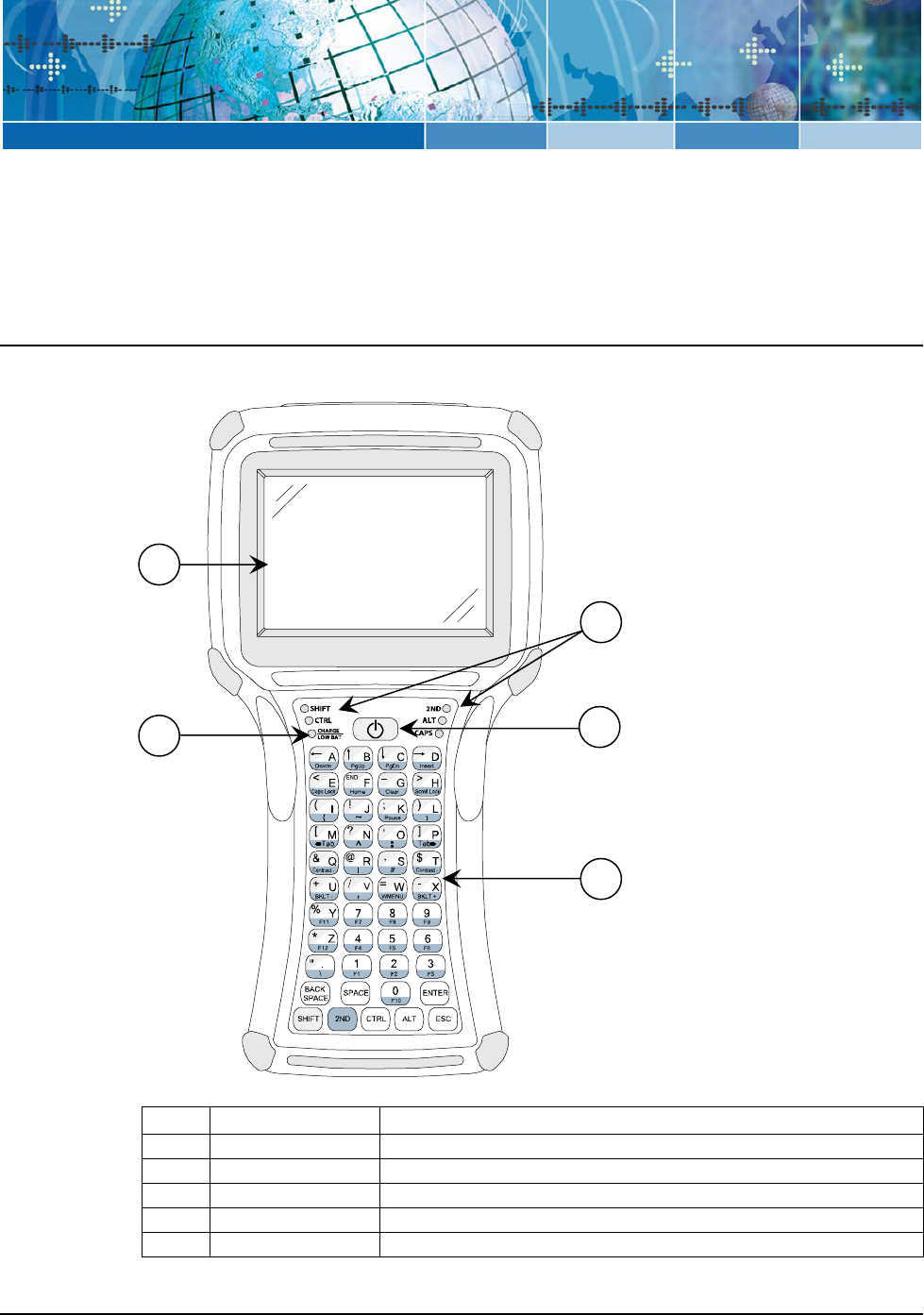
Front Components and Indicators
This section describes the components and indicators found on the font of the JETT•RFID.
Figure A-1: Front Components and Indicators
Table 2-1: Front Components and Indicators
Item Function Description
1 Display Supertwist nematic liquid crystal display with touch screen
2 Battery Indicator Indicates low battery (red) status and charging (green) status
3 LEDs Indicates use of the SHIFT, CTRL, 2ND ALT and CAPS modifier keys
4 On/Off Switch Controls the Power, Suspend and Resume operations
5 Keypad Standard 45-key keypad (30 and 15-key keypads not shown)
5
2
3
4
1
2
-1
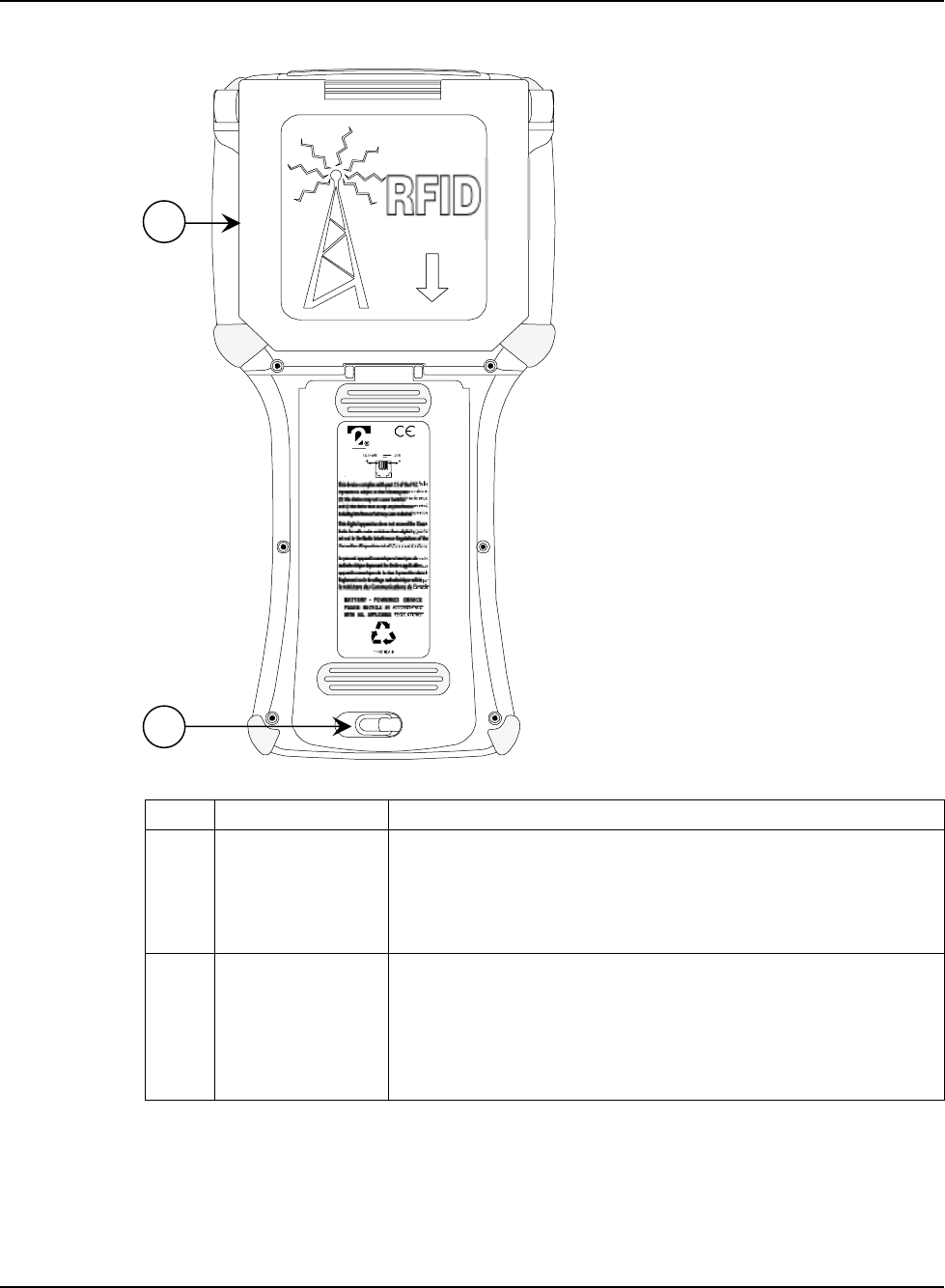
Rear Components
This section describes the components found on the rear of the JETT•RFID.
Figure A-1: Rear Components
OPEN Antenna for
Maximum Range
Table 2-2: Rear Components
Item Function Description
1 RFID Module The RFID Module attached to the rear of the unit can read RFID tags
in its storage position (show above) or swing out up to 180 degrees
for maximum range.
For more information about using the RFID module, see Using the
RFID Module.
2 Battery
Compartment
The battery compartment can store either the Nickel Metal Hydride
rechargeable battery pack or six AA Alkaline batteries. You can
access the battery compartment by lifting up and turning the
retaining clip.
For more information using batteries, see Battery-Powered
Operation.
2
1
JETT•RFID Components
2
-2
Compact Flash Slot
The compact flash slot located on the top of the unit enable you to insert and remove memory and
device cards. For more information, see Inserting and Removing Cards.
Figure A-1: Compact Flash Slot in Closed Position
Figure A-2: Compact Flash Slot in Open Position
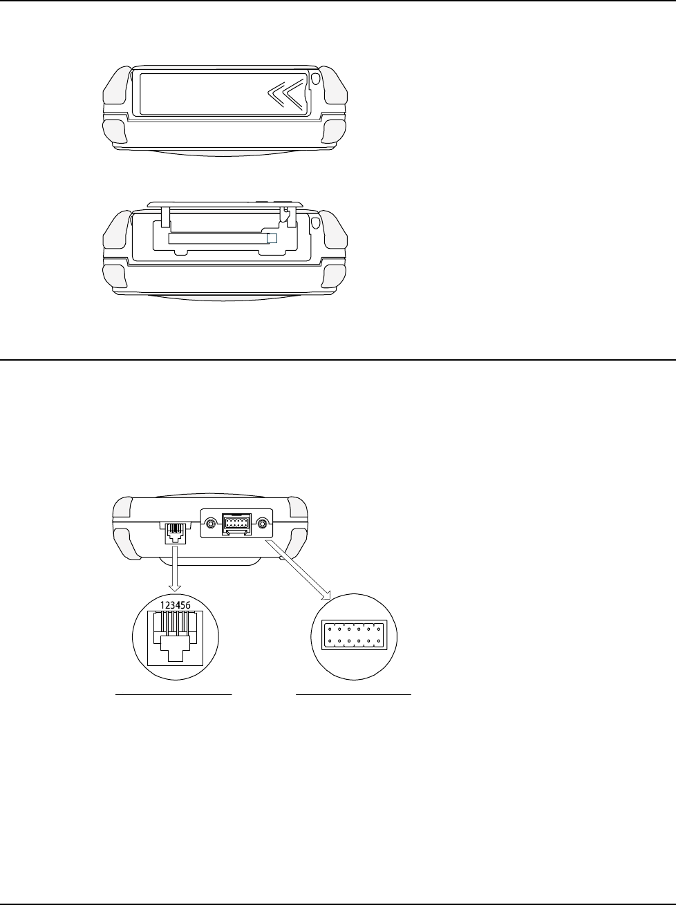
Interface Connections
This section describes the JETT•connect port and optional modular connector found on the bottom of
the JETT•RFID. These connections (factory configurable) provide serial communication and output
power at 5 VDC to operate peripheral devices such as bar code scanner.
The JETT•connect port also provide power input at 11 to 18 VDC for line-power or battery charging
operations.
Figure A-1: Interface Connections with Standard RS-232 Pin and Signal Assignments
Viewed Facing Connector
Pin 1 = Ground
Pin 2 = RXD
Pin 3 = TXD
Pin 4 = RTS
Pin 5 = CTS
Pin 6 = +5 VDC Input
1
2
3
4
5
6
7
81012
911
Pin 1 = Reserved Pin 7 = DSR
Pin 2 = Ground Pin 8 = RTS
Pin 3 = RI Pin 9 = DCD
Pin 4 = CTS Pin 10 = +11-18 VDC Input
Pin 5 = DTR Pin 11 = Shield
Pin 6 = TXD Pin 12 =RXD
JETT•connect Interface
Modular Cable Interface
JETT•RFID Technical Reference Manual, MAN0339, Rev. A, Preliminary
2
-3
Cables and Connections
Two Technologies can provide the following optional power supplies, cable and adapters based on
communication and power requirements.
Table 2-3: Available Power Supplies, Cables and Adapters
Two Technologies
Part Number
Part Description
14508 11–18VDC Power Supply 1
91708 Black 15-Foot JETT•connect Cable (Male DE-9)
91709 Black 15-Foot JETT•connect Cable (Female DE-9)
1210-7-BK Black 7-Foot Coiled Modular-to-Modular Cable
1210-15-BK Black 15-Foot Coiled Modular-to-Modular Cable
CELAT-P Modular to DE-9S Adapter
1. Use of other power supplies may cause damage to the unit and void the warranty.
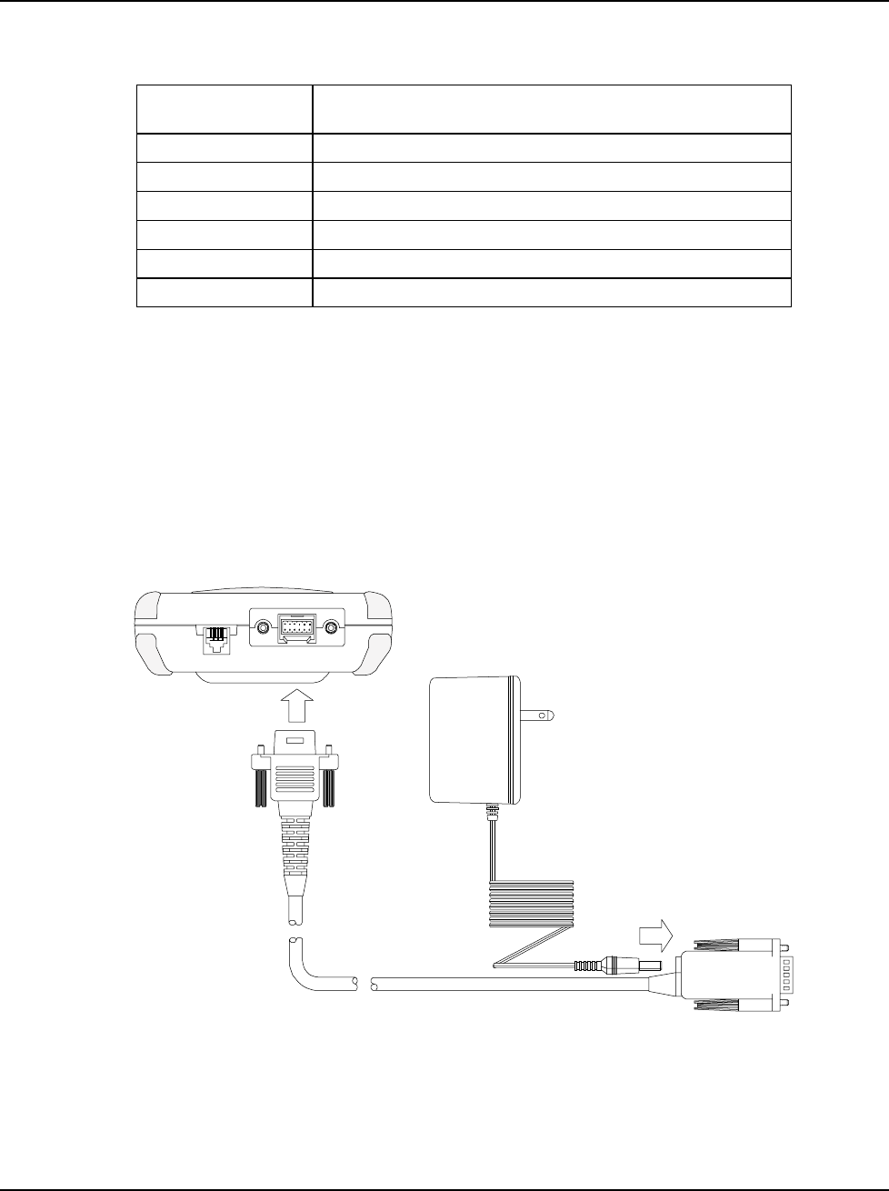
Cable Connections
JETT•connect System
The JETT•connect system is a set of rugged interface and cable connectors especially designed for
industrial environments. It features positive connector retention without any hardware restraints for
quick connect/disconnect operations and a contact design that prevents failure due to pin fatigue and
cable stress after repeated use. For JETT•connect cable signal and pin assignments, see Appendix B:
Signal and Pin Assignments.
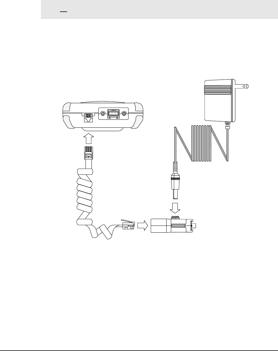
Figure A-1: JETT•connect Cable and Power Connections
Power Supply/
Battery Charger
Bottom of Unit
JETT•RFID Components
2
-4
1210 Series Modular Interface Cables
The uses a six-pin modular receptacle for compatible serial devices only. 1210 series modular interface
cables have reversing signals and connect to the auxiliary RS-232 serial port on the JETT•RFID and a
Two Technologies’ CELAT-P adapter. For 1210 series modular interface cable signal and pin
assignments, see Appendix B: Signal and Pin Assignments
Warning! Despite its physical similarity to modular telephone connectors, the 1210 series modular interface
cable is not compatible with telephone lines or signals. Connecting the JETT•RFID to a telephone line will
damage it and void the warranty.
To connect power to the JETT•RFID using a 1210 series modular interface cable and a CELAT-P
adaptor:
1. Plug one end of the 1210 modular cable into the modular connector on the bottom of the
JETT•RFID. Plug the other end into the CELAT-P adapter. See Figure A-1.
2. Plug the power supply connector into the CELAT-P adapter. Plug the power supply
transformer into a power outlet.
Figure A-1: Auxiliary Port Cable Connections
Modular Cable
CELAT-P Adapter
Power Supply/
Battery Charger
Bottom of Unit
JETT•RFID Technical Reference Manual, MAN0339, Rev. A, Preliminary
2
-5
JETT•RFID Technical Reference Manual, MAN0339, Rev. A, Preliminary
Chapter 3: Operation
Power
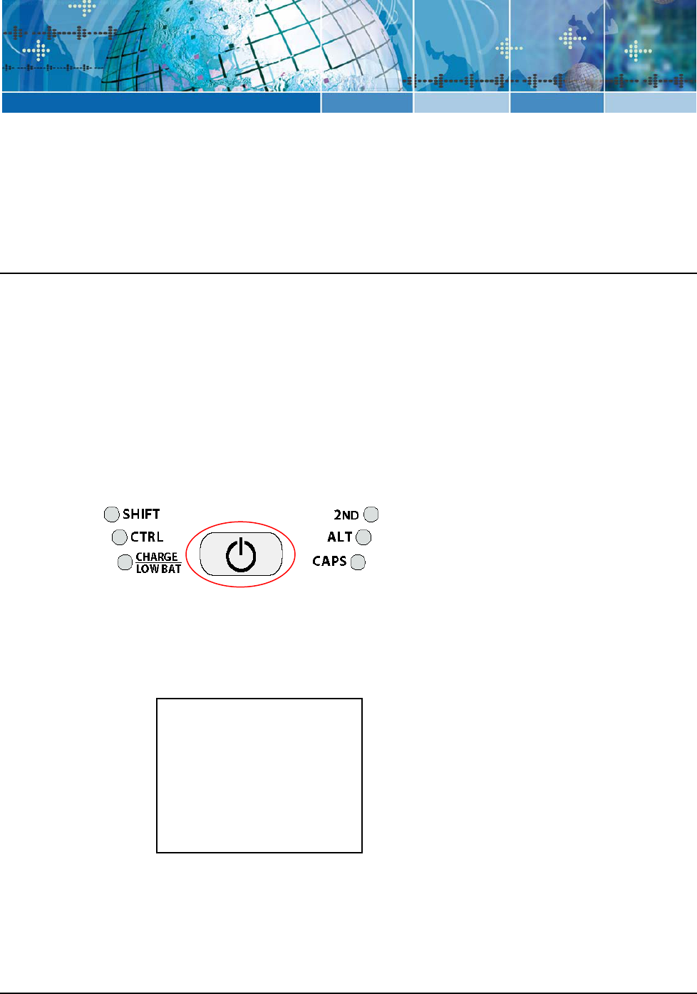
Power/Suspend Switch
The On/Off switch is located above the keypad. Its function depends on the state of the JETT•RFID at
the time the switch is pressed and on the length of time that the switch is depressed. Operations that the
Power switch can initiate are:
• Power On
• Power Off
• Suspend
• Reset (Warm Boot)
Figure A-1: Power/Suspend Switch
Power On
To power on the JETT•RFID:
1. Press and hold the ON/OFF switch for one second.
2. The unit should turn on and begin displaying the boot-up process. For example:
Where x.x.x is the version number
***** JETT.ce
*****
Loader Ver x.x.x Socket Booting from System
Loading CE image...
################ #
3. After approximately 20-25 seconds, the Windows CE .NET desktop should appear.
However, because there is no outward indication (such as a flashing LED) that the JETT•RFID
is powered off or in Suspend mode, the JETT•RFID may resume an active application if it is
indeed in a suspended state.
3-1

If the unit does not power up or you cannot select any items from the desktop, refer to the
“Troubleshooting” chapter for help.
Power Off
To turn off the JETT•RFID, press and hold the ON/Off switch for approximately eight seconds. This
action will also terminate running applications and cease serial port operations).
Suspend Mode
Suspend mode allows you to suspend, but not terminate active applications. In this mode, the display
will turn off and the JETT•RFID will cease serial port operations. For battery-powered units, use of
Suspend mode also conserves battery power.
To place the unit in Suspend mode, press and release the ON/Off switch.
To take the JETT•RFID out of Suspend mode, either touch the screen or press and release any key. The
display will turn on and the JETT•RFID will resume running any suspended application, but you must
restart any serial port operations.
If you attempt to resume immediately after suspending the JETT•RFID or vice versa, the unit will
automatically delay three seconds before resuming or suspending.
Reset
To reset (warm-boot) the JETT•RFID, press and hold the ON/Off switch between three and five
seconds. The screen should turn off, and the boot-up process should start. After approximately 20-25
seconds, the Windows CE .NET desktop should appear.
Note: Holding the Power/Resume button longer than six seconds will turn off the JETT•RFID.
Operation
3-2
Battery-Powered Operation
Battery-powered units can utilize a rechargeable Nickel Metal Hydride (NiMH) battery pack that has an
average operating time between ten and twelve hours on a full charge with power management and
approximately eight hours without power management. As with all battery-powered devices, the
operating time is completely dependent on the environment, device usage and the number and type of
power-drawing peripherals attached. The battery discharge rate in a full “Power Off” state is only
slightly higher to the self-discharge rate of the battery itself.
Note: Allowing the batteries to remain in a low or very low condition will cause the unit to enter Suspend
mode. In either case, you should save your work and recharge the unit as soon as possible
Power Management
To lengthen the time between charges, you can perform the following actions:
• Use external power for PC Card operations whenever possible— some PC Cards as well as
extended communication via the serial port, may require large amounts of power to operate,
and can quickly drain the batteries.
• Limit the use of backlight—minimize backlight use when you are operating on battery
power. You can adjust the backlight timeout level through the Display Settings in the Control
Panel or on some units by using the keypad.
• Shorten Auto-suspend time—the JETT•RFID is automatically set to suspend operation to
conserve battery power when you have not used the keyboard or the stylus after three
minutes. You can increase the Auto-suspend time by changing the Power settings in the
Control Panel.
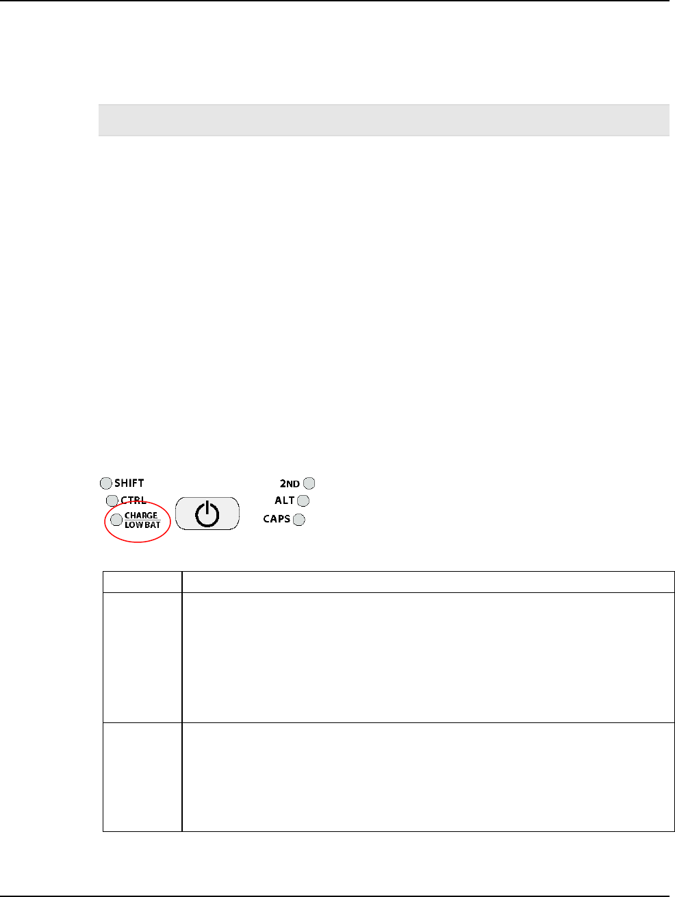
Charge\Low Battery Indicator
When using batteries, the CHARGE/LOW BAT LED will indicate the current battery status as shown in
Table 3-1.
Figure A-1: Charge\Low Battery Indicator
Table 3-1: Charge\Low Battery Indicator Functions
Function Description
CHARGE With the power supply connected, the CHARGE/LOW BAT LED will indicate one of
following conditions:
High Power Charge—the LED will turn solid green
Fully/Near Full Charge—the LED will blink green about four times a second
Trickle Charge—the LED will blink green approximately once per second
when either the battery voltage and/or temperature of the battery assembly
are not within acceptable limits
LOW BAT With the power supply disconnected, the CHARGE/LOW BAT LED will indicate one
of following conditions:
Batteries are low— the CHARGE/LOW BAT LED will blink red once per
second when there is approximately 60 minutes of power remaining
Batteries are very low—the CHARGE/LOW BAT LED will turn solid red
when there is approximately 10 minutes of power is remaining
JETT•RFID Technical Reference Manual, MAN0339, Rev. A, Preliminary 3-3
Charging the Unit
The nickel metal hydride battery technology used in the JETT•RFID has exceptional charge life without
the “charge memory” characteristic of conventional nickel cadmium batteries. Partially discharged bat-
teries or extended periods with the charger left connected will not adversely affect battery life or per-
formance.
Note: Because the internal battery charger senses several conditions, including temperature, you should
charge the unit away from any known or potential heat sources. Units exposed to temperatures in excess
of 110 degrees Fahrenheit during the charge cycle may experience incomplete charging and reduced
operating time per charge.
To charge a battery-powered JETT•RFID:
1. Plug the power supply connector into the corresponding connector on the bottom of the
JETT•RFID. Plug the power supply transformer into a power outlet. See Figure A-1.
2. The Charge LED should turn on, indicating that the batteries are charging. While the
JETT•RFID is charging, you can still use it.
3. Once the battery is fully charged (approximately three hours), you can disconnect the AC
power supply and run the JETT•RFID exclusively on battery power.
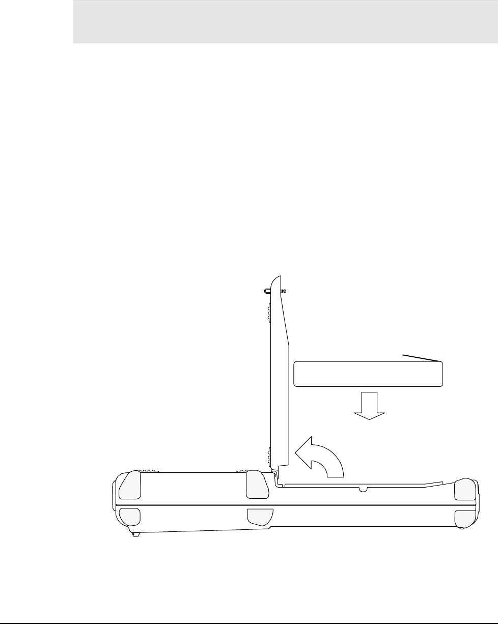
Changing Batteries
To change batteries:
1. With the unit face down, pull the battery cover retaining clip up from its recessed slot and turn
the clip in a counter clockwise motion.
2. Lift the cover up and remove the batteries.
3. If the unit contains a battery pack, use the tab on the battery pack to lift up and then out.
Figure A-1: Changing Batteries
Battery Pack Cover Battery Pack
Tab
Retaining Clip
4. Insert the new batteries or battery pack into the unit using the orientation shown in Figure
A-2.
Operation
3-4
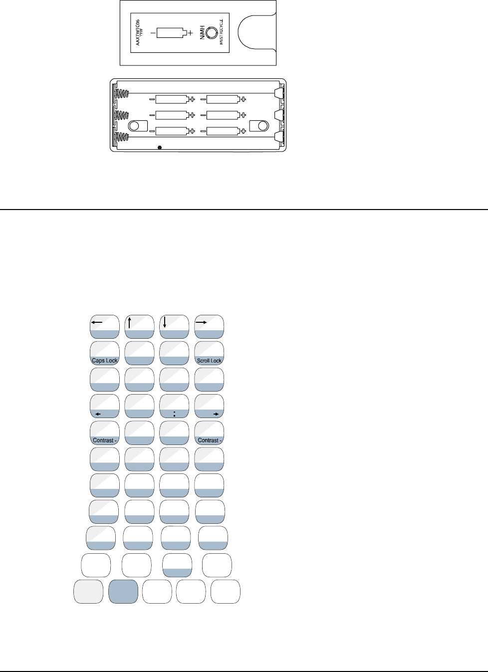
Figure A-2: Battery Orientation
5. Close the battery cover and turn the battery cover retaining clip clockwise to lock the cover.
Data Entry
45-Key Keypad
In order to provide the functionality of a full-sized keyboard with only 45 keys, the JETT•RFID keypad
must depart from PC-style key assignment conventions. Units configured with the standard 45-key
keypad typically utilize five LED indicators (located above the ON/OFF switch) to indicate the active
state of keypad modifier keys. Units with internal batteries also use a LED to indicate the battery status
(Table 3-1). Units with 45-key keypads also have keypad functions to adjust the contrast and backlight.
Figure A-1: 45-Key Keypad
G
A
Delete B
PgUp C
PgDn D
Insert
E F
Home H
I
{J
~
KL
}
<END _>
^
Pause
(!;)
[?']
RST
#
Q
&@$
U
+V
,
/X
BKLT +
-
W
=
Y
%7
F7
9
F9
8
F8
Z
*4
F4
6
F6
5
F5
.
\
1
F1
2
F2
3
F3
0
F10
BACK
SPACE SPACE ENTER
SHIFT 2ND CTRL ALT ESC
BKLT -
"
Clear
OMN P
Tab Tab
,
WMENU
F11
F12
|
JETT•RFID Technical Reference Manual, MAN0339, Rev. A, Preliminary 3-5
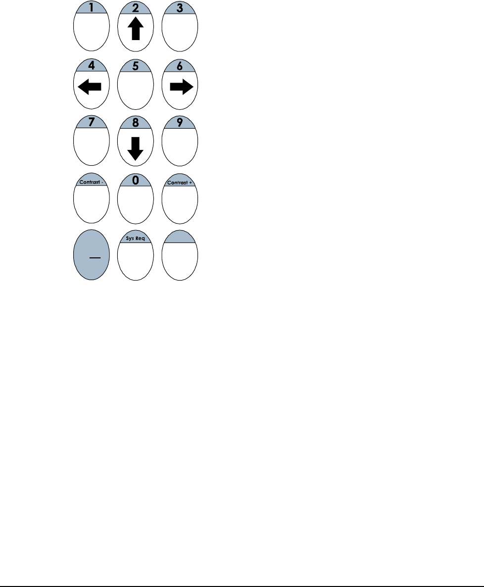
15-Key Keypad
Typically, units with a 15-key keypad will function differently than the keypad legends indicate. This
feature provides you a method of navigating and using Windows CE .NET until you configure and
map your keypad in the context of your application using JETTkbtool.
Figure A-1 shows the default functions.
Figure A-1: 15-Key Keypad
TAB ALT
\
-+
ESC .ENTER
2ND CTRL
Back
Space
SPACE
Modifier Keys
The following modifier keys (located on the bottom of a standard keypad) enable you to access the
various functions that can appear on a key. Figure A-1 provides an example. Modifier keys take effect
when first pressed and typically remain in effect until you press another key, unless its another
Modifier key. Optionally equipped units can use LEDs to indicate the selection of a Modifier key.
CTRL and ALT Keys
CTRL and ALT keys operate in the same manner as on conventional PCs, except that by default they
have a one-time locking action to facilitate one-handed operation.
SHIFT Key
Unlike conventional PC keyboards, the SHIFT key enables you to access symbols, punctuation marks
and navigation arrows rather than shift alphabetic keys to uppercase. The SHIFT key has a one-time
locking action to facilitate one-handed operation.
On standard JETT•RFID keypads, the functions and characters accessed via the SHIFT key appear in
the upper left of a key, shaded in gray.
Operation
3-6
2ND Key
The 2ND Key shifts the numeric keys to corresponding function keys (1 = F1, 2 =F2, etc.) that are found
on conventional PC keyboards.
It also shifts other keys for punctuation, non-printing characters (such as Delete and TAB), and PC key
definitions (such as PageUp, PageDown, Home, Insert and Caps Lock). Like other Modifier keys, the
2nd key has a one-time locking action to facilitate one-handed operation.
On the standard JETT•RFID keypad, the functions and characters accessed via the 2nd key appear at
the bottom of a key, shaded in blue.
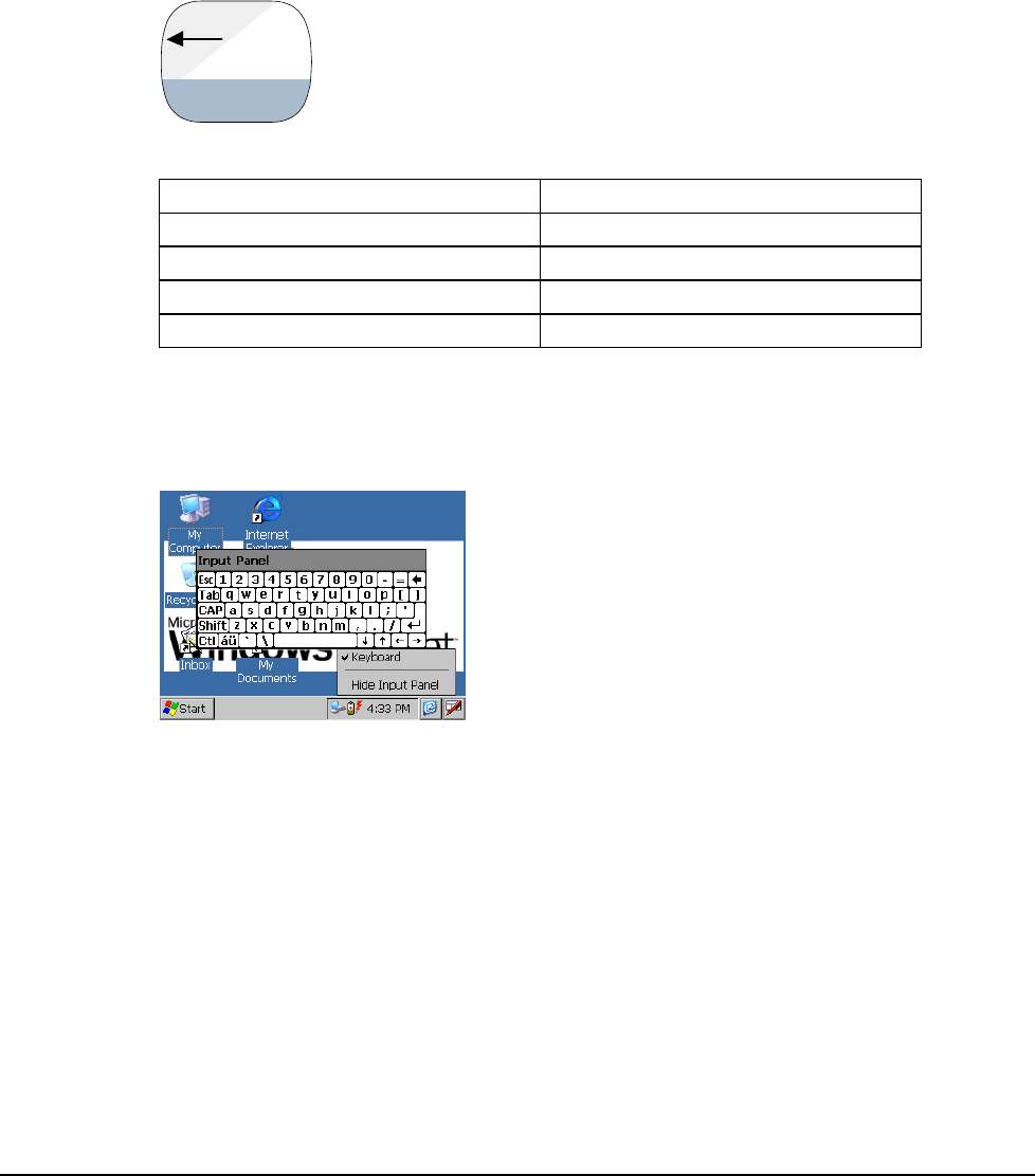
Figure A-1: Multifunctional Key
A
Delete
Table 3-2: Modifier Key Actions
Key Presses Result
A Lowercase “a”
Shift & A Move cursor left one position
2ND & A Delete Character
2ND & Caps Lock Uppercase “A”
Input Panel
In addition to entering data through the keypad, you can also enter data by tapping the Input Panel
icon located in the system area of the taskbar.
Figure A-1: Input Panel
JETT•RFID Technical Reference Manual, MAN0339, Rev. A, Preliminary 3-7
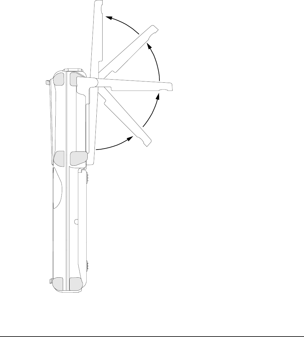
Using the RFID Module
The RFID module can read and write (up to 16k bits) most industry standard 13.56MHz RFID tags and
smart labels including ISO-15693, ISO-14443, Philips Mifare, Tag-It by Texas Instruments, Icode by
Philips, my-d from Infineon, LRI512 by ST Microelectronics, GemWave by TagSys, and PicoTag from
Inside Contactless.
The RFID module is totally application dependent and derives power from the COM2 port. The RFID
module has a flip-out antenna that provides a read range of approximately 3.5 inches (90mm) with a
credit card size tag at 90 degrees (see illustration below).
For RFID module application integration information, contact Two Technologies.
Figure A-1: RFID Read Range
0º
180º
90º
Operation
3-8
The Windows CE .NET Desktop
Note: Due to limitations and sizing constraints, some features and functions of the Windows CE .NET
Professional operating system (such as Bluetooth and Windows Media Player) may not be available or not
available on the JETT•RFID at time of this writing.
This section provides a brief overview of the functions that appear on the JETT•RFID desktop. For
information on how to change desktop settings, refer to the unit’s on-line help.
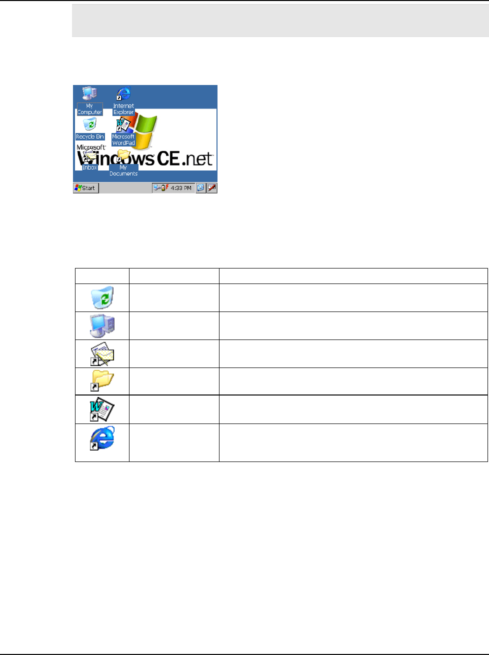
Figure A-1: Windows CE .NET Desktop
Desktop Functions
You can access the following applications, functions and data entry utilities from the JETT•RFID
desktop:
Table 3-3: Desktop Functions
Icon Function Description
Recycle Bin Use the Recycle Bin to restore deleted files or empty the bin to
create more disk space.
My Computer Use My Computer to navigate and view the folders and files
stored on the JETT•RFID.
Inbox Use the Inbox to send and receive e-mail by connecting to a
POP3 or IMAP4 server.
My Documents The default storage location for documents, graphics, and other
files.
Microsoft WordPad Use WordPad to create or edit text files that contain formatting
or graphics.
Internet Explorer Use Pocket Internet Explorer to view Web pages. You will need
a modem or Ethernet card to connect to an Internet service
provider (ISP) or network.
JETT•RFID Technical Reference Manual, MAN0339, Rev. A, Preliminary 3-9
The Taskbar
The taskbar at the bottom of the JETT•RFID desktop displays the Start button, buttons of currently
running applications, the Status Area and the Show Desktop icon.
Figure A-1: Windows CE .NET Desktop Taskbar
Tap the Start button to display the Start menu (see below for details). For each open application, a
button appears on the taskbar. Simply tap the application’s button to activate it.
The status area appears on the right and by default displays small icons for the input panel, current
time, power status and network connections. Tap a small icon to activate the related program.
Tapping the Show Desktop icon minimizes active applications and redisplays the desktop. Tapping the
Keyboard icon displays the Input Panel menu for data entry.
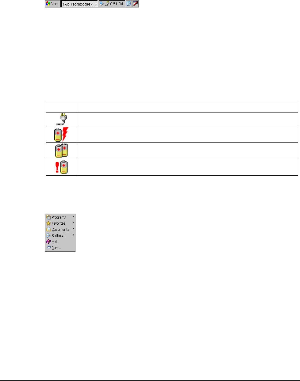
Power Status Icons
The JETT•RFID will display power status icons (Table 3-4) in the taskbar status area (Figure A-1) to
indicate power use, charging status and low battery conditions.
Table 3-4: Power Status Icons
Icon Description
External AC power supply connected
Batteries are charging
Batteries are low—approximately 60 minutes or less of use remaining (the
CHARGE/LOW BAT LED will blink red once per second)
Batteries are very low—approximately 10 minutes or less of use remaining (the
CHARGE/LOW BAT LED will turn solid red)
The Start Menu
When you tap Start, the Start menu appears.
Figure A-1: Start Menu
From this menu, you can:
• Open programs that do not appear on the desktop
• View a list of web sites added to your Favorites List
• View recently accessed documents and images
• Access the Control Panel, establish connections, or configure the Taskbar and Start Menu
• View Help
• Start an application using the Run command
• Place the unit in Suspend mode
Operation
3-10
Using ActiveSync
To download applications to the JETT•RFID’s flash memory requires Microsoft ActiveSync 3.7 and a
serial connection between the JETT•RFID and the JETT•RFID Development System.
If you have a version of Microsoft ActiveSync earlier than version 3.7, you should remove the program
from the development system before installing ActiveSync 3.7. If you have a version of ActiveSync
installed, but unsure of the version, start the program and select About Microsoft ActiveSync from the
Help menu.
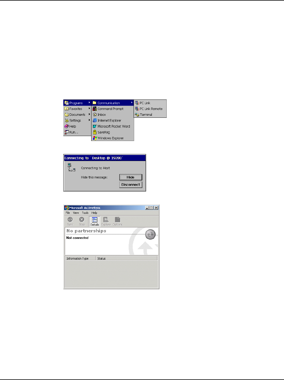
Initial Communication
To setup initial communication between the development system and the JETT•RFID:
1. Connect the JETT•RFID interface cable to an available COM port on the development system
and the COM 1 port of the JETT•RFID.
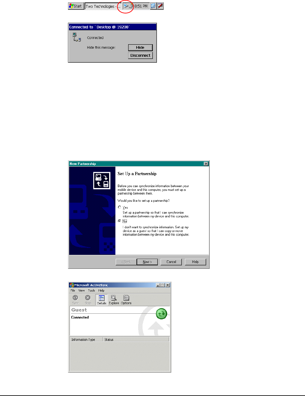
2. On the JETT•RFID, tap Start and then select Programs > Communications > PC Link.
The following message box appears:
3. On the development system, start ActiveSync.
4. From the File menu, select Get Connected. The ActiveSync Get Connected dialog box opens.
5. Click Next. ActiveSync will then attempt to connect to the JETT•RFID.
JETT•RFID Technical Reference Manual, MAN0339, Rev. A, Preliminary 3-11
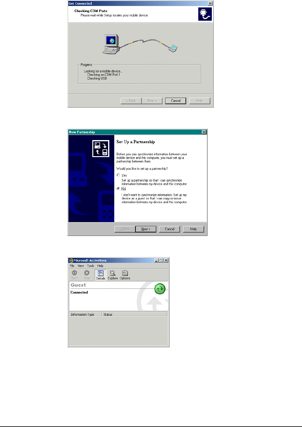
6. If the system successfully establishes communications, the connecting message on the
JETT•RFID will close and the Set Up a Partnership dialog box will appear on the PC.
7. On the Set Up a Partnership dialog box, select No and click Next. If a successful connection is
made the following dialog box will appear:
Operation
3-12
Disconnecting from the Development System
To disconnect from the development system:
1. In the JETT•RFID system tray, double-tap the connection icon
2. The Connection Message appears.
3. Tap Disconnect.
Subsequent Communication
After you install ActiveSync and establish the initial communication between the development system
and the JETT•RFID, use the following procedure to set up subsequent sessions:
1. If not already attached, connect the JETT•RFID interface cable to an available COM port on the
JETT•RFID Development System and to the COM 1 port of the JETT•RFID.
2. On the JETT•RFID desktop, tap Start then select Programs > Communications > PC Link. The
system will then attempt to reestablish communications
3. After the system reestablishes communications, the Set Up a Partnership dialog box appears
on the development system.
4. Select No and click Next. A status of “Connected” should appear in the ActiveSync window.
JETT•RFID Technical Reference Manual, MAN0339, Rev. A, Preliminary 3-13
Persistent Registry
Saving Changes to the Registry
The JETT•RFID internal memory consists of DRAM and Flash. Typically, any changes made to the
JETT•RFID including file creation are temporarily stored in the unit’s DRAM. You must then copy the
files from DRAM to internal flash memory or a removable compact flash card to store the information
permanently. Consequently, if you do not store the information to flash memory and the unit loses
power, all information stored in DRAM will be lost. However, whenever you make changes that affect
the registry, such and changing settings in the Control Panel or installing software, you can
permanently store registry changes without writing to flash memory by using the Persistent Registry.
Note: The JETT•RFID will also store registry information when you perform a suspend operation.
To store registry information on the JETT•RFID permanently:
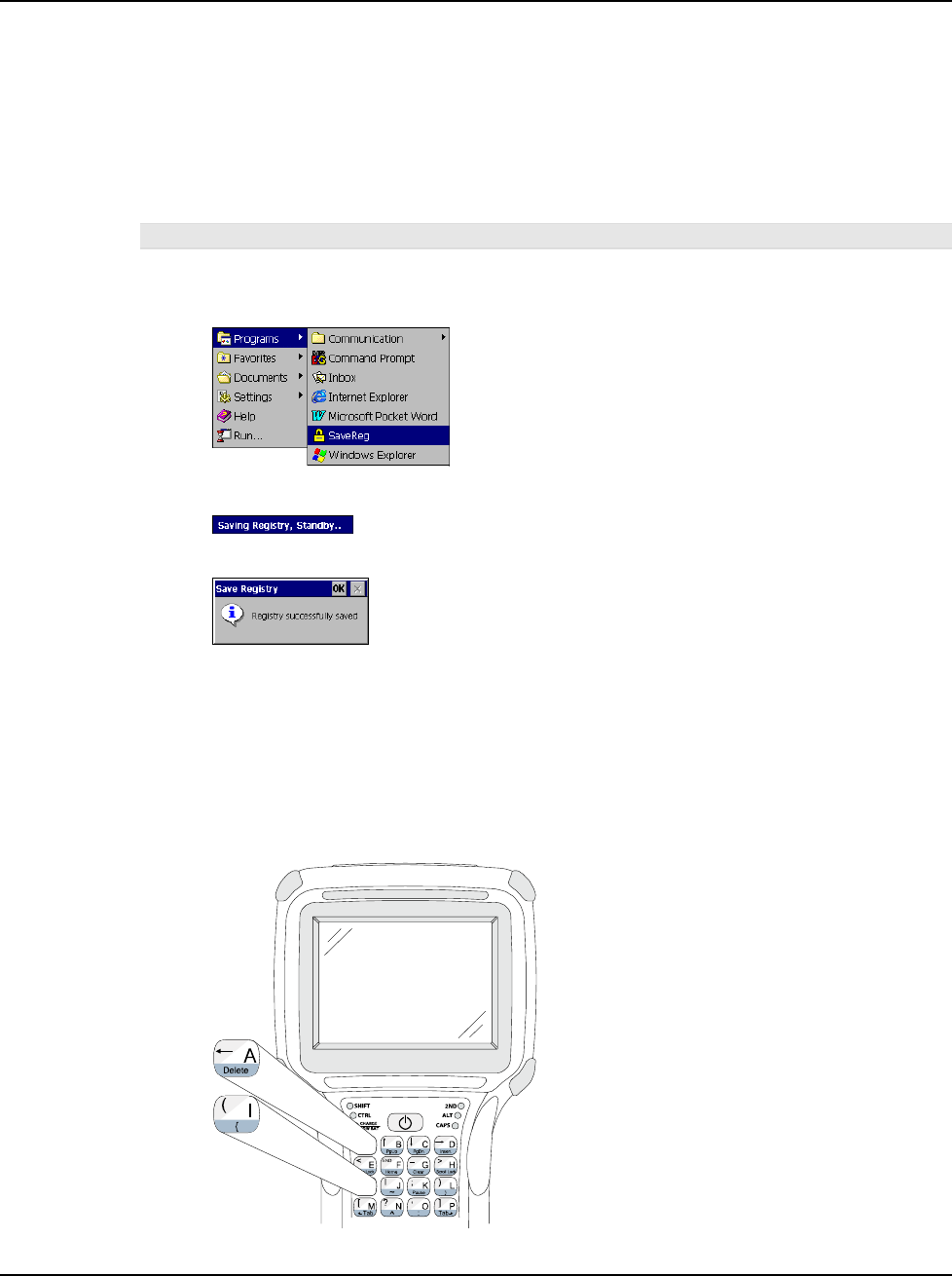
1. From the Start menu, select Programs and tap SaveReg.
2. The JETT•RFID will begin saving the registry.
After you successfully save the registry, a message box will appear:
3. Tap OK to close the message box.
Resetting the Registry
To reset the Windows CE .NET registry back to the factory default settings:
1. Turn off the JETT•RFID.
2. While holding the key in Column 1, Row 1 (upper leftmost) and the key in Column 1, Row 3,
turn on the JETT•RFID. For example:
Operation
3-14
3. If you are successful, the screen will display version information, followed by “Invalidating
Persistent Registry,” before it completes the boot up process: For example:
Where x.x.x is the version number
***** JETT.ce
*****
Loader Ver x.x.x
Invalidating Persistent
Registry Socket Booting from System
Loading CE image...
#################
Using the Compact Flash Slot
The top of the JETT•RFID has an access panel to a Compact Flash (CF) slot. Through this slot, you can
insert compact flash and device cards.
If you intend to use a device card, it may be necessary to install a driver. If so, make sure the card is
Windows CE .net compatible and you have the necessary drivers. If you are not sure, check with the
card manufacturer before attempting to install the card
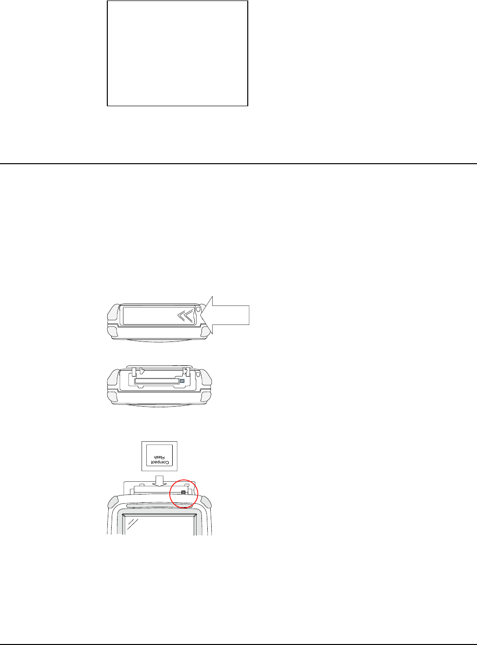
Inserting and Removing Cards
To insert a card:
1. With the front of the display facing you, push the compact flash slot cover (located on top of
the unit) to the left.
Push
2. The slot cover will automatically pop open.
3. Insert the compact flash/device card into the slot with the front of the display facing you and
the top of the card pointed to the slot until it clicks and the release lever moves upward.
Release Lever
4. Close the cover.
5. For device cards, the JETT•RFID will attempt to recognize the device and display a dialog box.
6. If it finds a driver for the device, the JETT•RFID will display a dialog box for that device. For
example:
JETT•RFID Technical Reference Manual, MAN0339, Rev. A, Preliminary 3-15
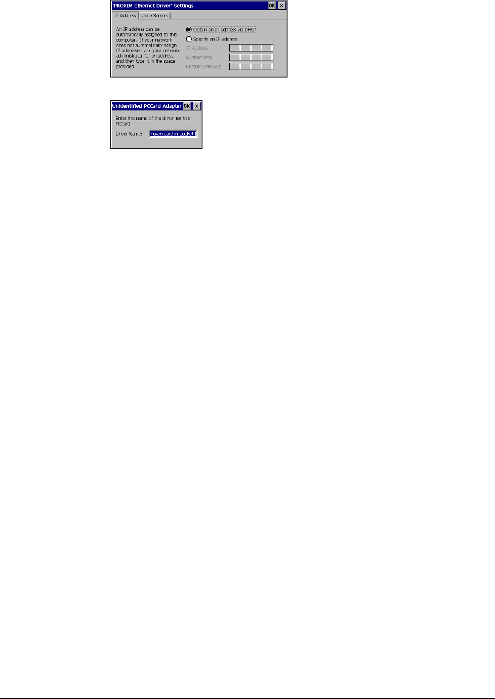
If the JETT•RFID cannot find a driver for the device, it will display the following dialog:
7. If the correct card type appears, you can enter the appropriate information in the dialog box as
required and then tap OK to complete the installation.
If the JETT•RFID cannot find the correct driver for the device or you wish to install the driver
that came with the card, you must first install/copy the software supplied by the card
manufacturer to a host computer and then install/transfer the necessary files to the unit
(typically using ActiveSync).
To remove a card from a slot, simply push the card release lever down and remove the card.
Operation
3-16
JETT•RFID Technical Reference Manual, MAN0339, Rev. A, Preliminary
Chapter 4: Configuration
The Control Panel
The table below lists the available control panel functions on the JETT•RFID.
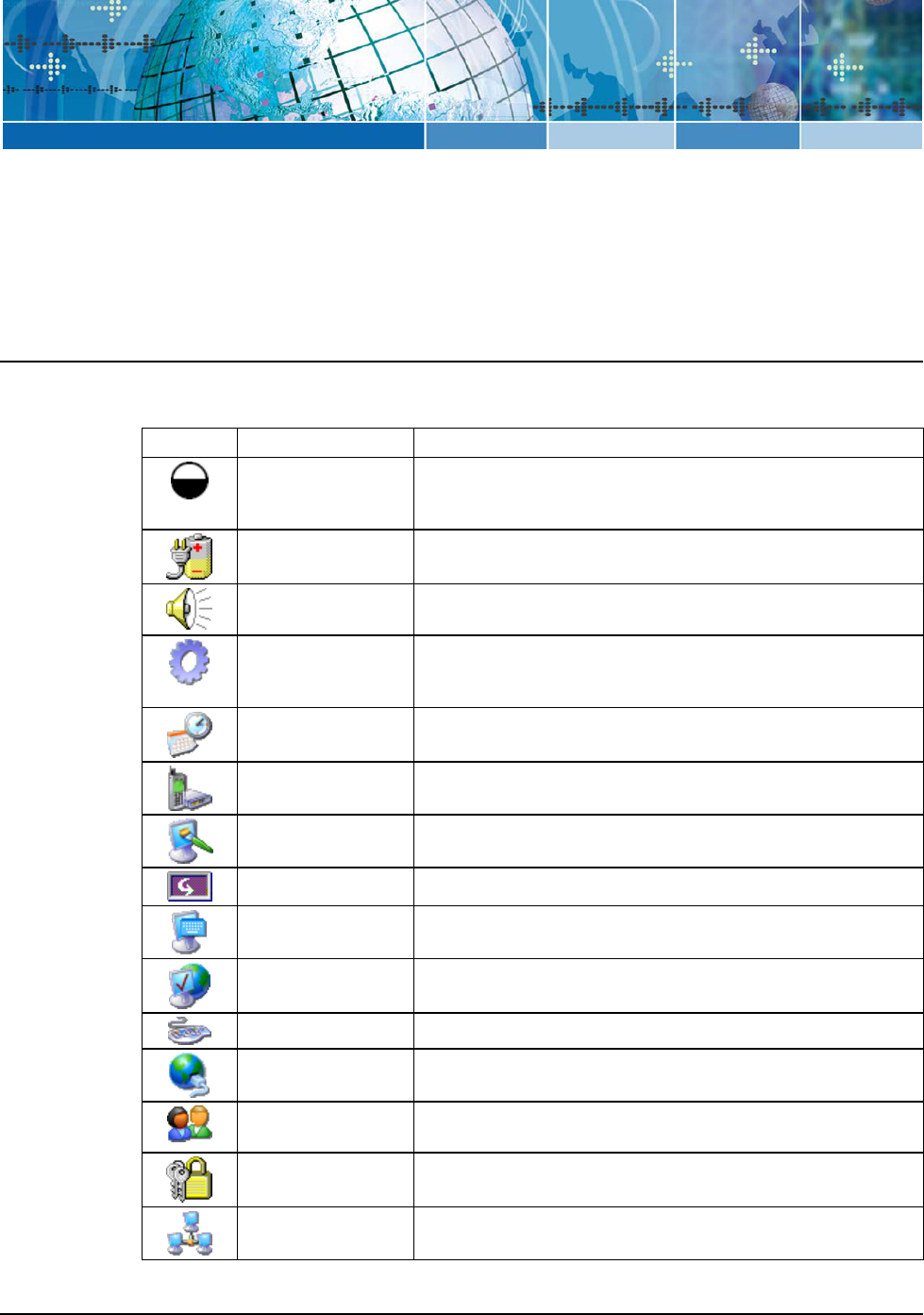
Table 4-1: Control Panel Functions
Icon Function Description
Backlight Use this function to adjust the backlight setting for the following
conditions: Line Active, Line Active Inactive, Battery Active and
Battery Inactive.
Battery Select Select one of the following options to calibrate the power status
icons for proper use: NIMH, AC Line or Alkaline.
Beep Select Use this function to change the frequency, volume and duration
properties of the beep.
Certificates Use this function to import, view or remove certificates, which
protect your personal information on the Internet, and protect
your computer from unsafe software.
Date/Time Use this function to adjust the date, time and time zone.
Dialing Use this function to adjust the dialing location settings and
dialing patterns when using a modem.
Display Use this function to adjust the backlight timeout, change the
background image or change the desktop color scheme.
Display Rotation Use this function to rotate the screen 180 degrees (upside down).
Input Panel Use this function to adjust the settings for the input panel.
Internet Options Use this function to set up connections, security settings and
internet related functions.
Keyboard Use this function to change the repeat delay and repeat rate.
Network and
Dial-up Connections
Use this function to change network adapter settings and/or set
up identification for remote networks.
Owner Use this function to enter the owner name, address, phone
numbers and network ID.
Password Use this function to enable password protection and set a
password.
PC Connection Use this function to enable direct connection to a desktop
computer
4
-1
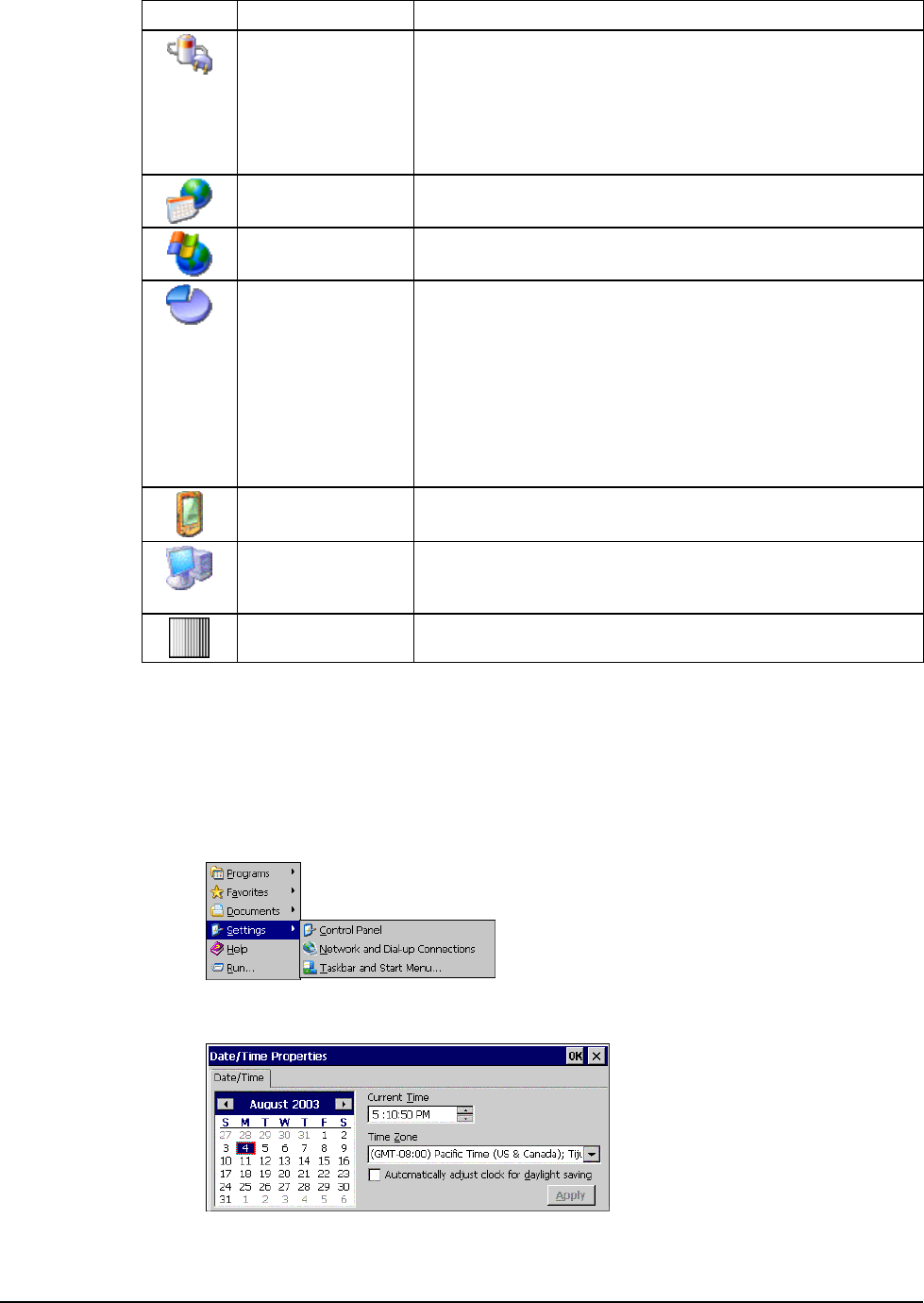
Icon Function Description
Power Use this function to:
Check battery power
Set device to turn off when idle
Set up power schemes
Check the power levels of your system devices
Regional Settings Use this function to change the appearance of region specific
information, such as date, time and currency.
Remove Programs This function enables you to remove programs installed in RAM.
Storage Manager This function enables you to perform the following tasks:
• View partition information
• Format a partition
• Create or delete a partition
• Mount or dismount a partition
• Scan and repair a partition.
• Defragment a partition
Stylus Use this function to recalibrate the touch screen and adjust the
stylus double-tap rate.
System Use this function to view system information, change the RAM
(Program/Storage memory) division, change the device name
and change the device description..
VComAdj Use this function to minimize screen flicker and adjust contrast.
Changing System Settings
Any time you make changes through the Control Panel (such changing the time zone), you must also
update the persistent registry to store the changes in internal compact flash memory to make the
changes permanent.
For example, to change the time zone and save the changes to the registry:
1. From the Start menu, tap Settings and select Control Panel.
2. On the Control Panel, double-tap the Date/Time icon. The Date/Time Properties dialog box
appears. You can now set the date, time and time zone.
Configuration
4
-2
3. To adjust the Current Time, use the scroll bars to increase or decrease the value, or tap hours,
minutes, seconds or AM/PM indicator to set the values individually.
4. To select the Time Zone, use the corresponding list.
5. To adjust the Date, either:
Tap the arrows on the calendar to select the previous/next month
Double-tap the month or year to select it from a list
Tap a day to select it
6. To adjust the clock automatically for daylight savings, check the corresponding box.
7. Tap Apply to have your setting take effect.
8. Tap OK to close the Date/Time Properties dialog box and return to the Control Panel.
9. Tap OK to exit the Control Panel.
10. From the Start menu, select Programs and tap Save Registry.
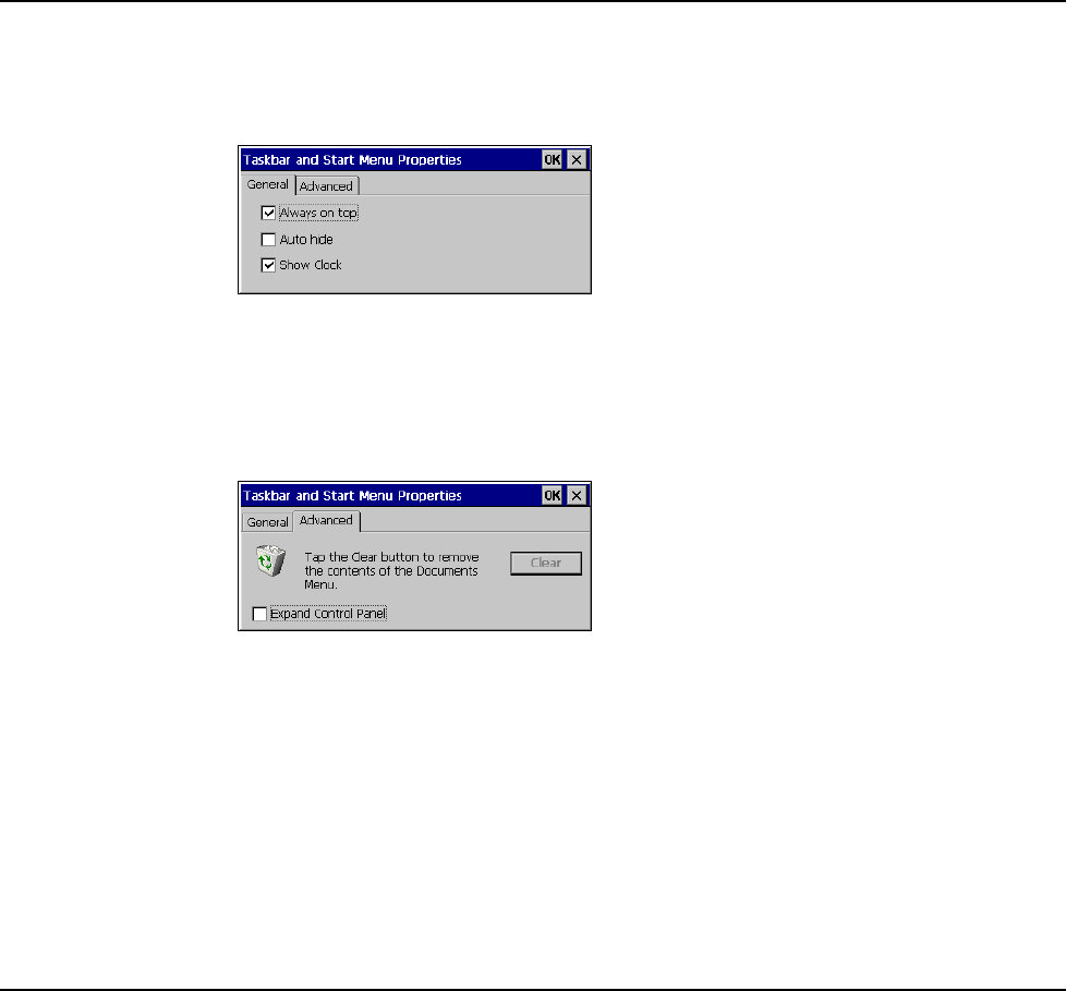
Taskbar and Start Menu Settings
To change the Taskbar and Start Menu settings:
1. Select Start > Settings> Taskbar & Start Menu. The Taskbar and Start Menu Properties dialog
box opens:
2. Select the General tab:
3. Check Always on Top to ensure that the taskbar is always visible, even when a program
appears in a full window (maximized).
4. Check Auto hide to display the taskbar just when you point to the taskbar area.
5. Check Show Clock to display the time of day in the taskbar.
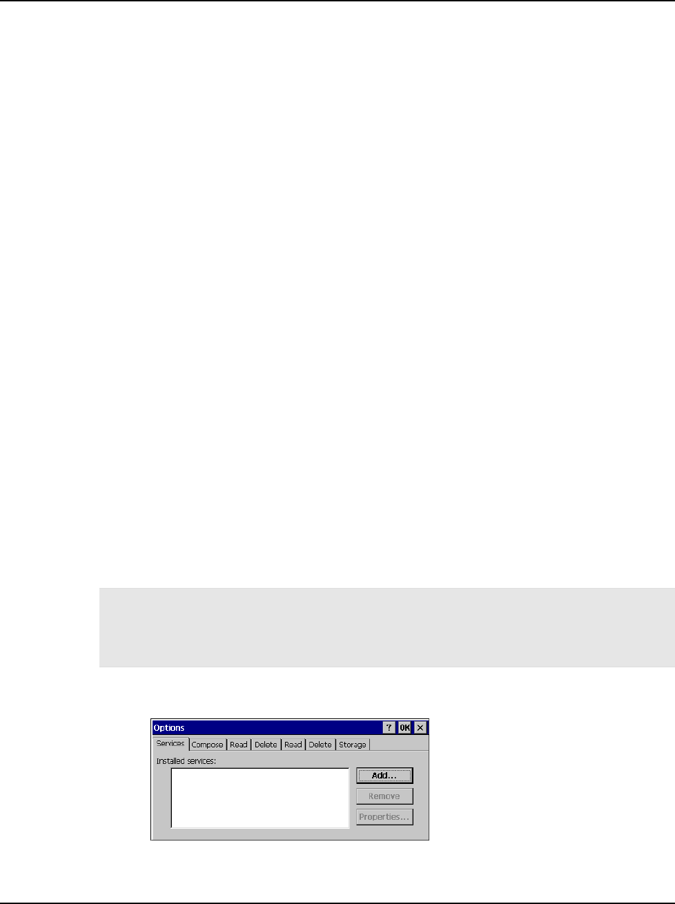
6. Select the Advanced tab:
7. Tap the Clear button to remove the contents of the documents menu.
8. Check the Expand Control Panel box to display the contents of the Control Panel as items on
the Settings| Control Panel menu.
9. Tap OK to save the settings and exit the menu.
10. From the Start menu, select Programs and tap Save Registry.
JETT•RFID Technical Reference Manual, MAN0339, Rev. A, Preliminary
4
-3
Network Connections
You can connect directly to a network through an Ethernet or dial-up connection to access e-mail,
access files available on the network server, and browse the Internet.
Creating a Network (Ethernet) Connection
To create a network (Ethernet) connection:
1. On your device, insert the Ethernet card.
2. Select Start > Settings > Control Panel. Tap the Network and Dialup Connections icon.
3. Double-tap the connection icon for the adapter. For example, if you have a NE2000 Ethernet
adapter, double-click the NE2000 connection icon.
4. In the Ethernet Driver Settings dialog box, select Obtain an IP address via DHCP and tap OK.
5. If prompted, enter the User Name, Password, and Domain name you use to log on to your
network.
6. From the Start menu, select Programs and tap Save Registry.
Setting Up Identification for Remote Networks
To set up identification for remote networks:
1. Select Start > Settings > Control Panel.
2. Open the Owner icon.
3. In the Network ID tab, enter the user name, password, and domain name you use to log on to
the remote network.
4. From the Start menu, select Programs and tap Save Registry.
Connecting to a Mail Server
You can send and receive e-mail by connecting to a POP3 or IMAP4 server. Inbox contains an e-mail
service for each method you use. For either service, you must establish a connection to your Internet
service provider (ISP) or to the appropriate mail server in your local area network. In addition to
creating this connection, you must also create the e-mail service.
Prior to setting up a service, you should obtain the following information from your ISP or network
administrator: POP3 or IMAP4 server name, SMTP host name, user name, password and domain name
(for network connections only).
Notes: Windows CE .Net does not support other mail protocols such as AOL or services that use special
authentication, such as MSN. However, you can gain access to the Internet through these services. If you
use the same service to connect to different mailboxes, set up and name a different service for each
connection.
For additional information about the inbox, refer to Windows CE .NET online help.
To connect to your POP3 or IMAP4 mail server:
1. Open Inbox. Select the Services menu and choose Options. The Options dialog box opens.
2. Select the Services tab and tap Add. The Service Name dialog box opens.
Configuration
4
-4
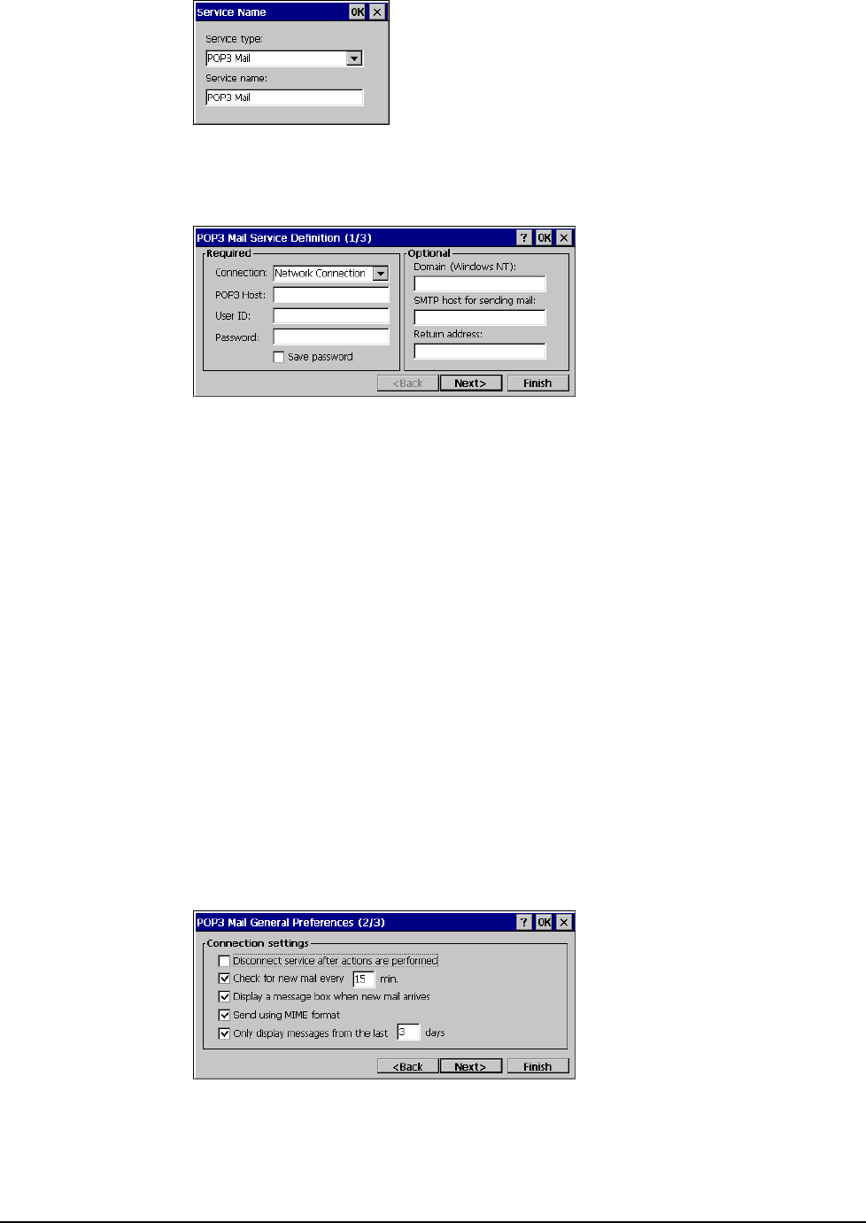
3. From the Service type list, select POP3 Mail or IMAP4 Mail.
4. Enter a unique name for the service (you cannot change this name once entered).
5. Tap OK. The Mail Service Setup wizard appears.
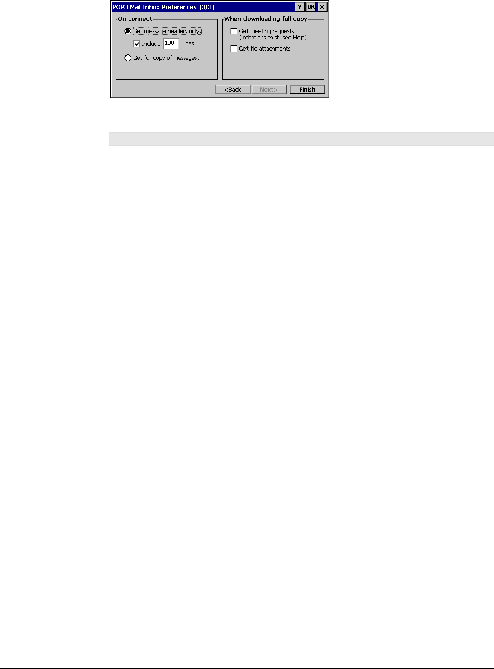
6. In the Required panel:
Select the name of the connection you created to connect to the mail server. If you are
receiving e-mail through a network (Ethernet) connection, select Network Connection.
If you want Inbox to use your current connection, select (none).
If you have not created a connection, select Create new connection, double-tap the Make
New Connection icon, and follow the instructions in the wizard. When finished, select
Inbox in the Taskbar and continue setting up Inbox.
Enter the POP3 Host or Server (IMAP4) name of the mail server you use to receive and
send messages.
Enter the User ID (user name or mailbox ID) assigned to you.
Enter the password you will use to access this mail account. If you do not want a prompt
to enter the password each time you connect, select Save password.
7. In the Optional panel:
If connecting to a network that uses Windows NT domain security, enter the Windows
NT domain name.
If your mail service uses a separate server for SMTP, enter the SMTP Host name. For
POP3 Mail service with an ISP, the ISP must use an SMTP mail gateway.
Enter your return e-mail address.
8. Tap Next. The General Preferences dialog box opens.
JETT•RFID Technical Reference Manual, MAN0339, Rev. A, Preliminary
4
-5
9. Choose any of the settings, all of which are optional, then click Next. The Inbox Preferences
dialog box opens.
10. Choose any of the settings as needed, then click Finish. The Mail Service Setup wizard closes
and the Options dialog box reappears.
Note: Receiving entire messages consumes storage memory.
11. Close the Options dialog box to return to the Inbox.
12. From the Start menu, select Programs and tap Save Registry.
Configuration
4
-6

JETT•RFID Technical Reference Manual, MAN0339, Rev. A, Preliminary
Chapter 5: Application Development
Application Types
Before writing applications for Windows CE .NET 4.2 and the JETT•RFID, you will need to determine if
your applications will consist of managed code and/or native code.
• Managed code makes use of run-time environment application programming interfaces
(APIs), provides integrated security and memory management and is portable across software
platforms and processors. Code written in Microsoft Studio .NET 2003 is managed code.
• Native code uses a specific set of software platform APIs and microprocessor and as a result,
the compiled code will only run on that specific software platform and processor. Typically,
native code offers the highest performance with the smallest footprint, but it also requires
developers to write their own security and memory management code. Code written in
eMbedded Visual C++ is native code.
The type of application being created will dictate the choice between native and Microsoft .NET—
connected code. When a consistent programming model and time-to-market are the primary
considerations, use Visual Studio .NET and the .NET Compact Framework. When performance, the
smallest working set, and low-level control are a top priority, use eMbedded Visual C++.
Development Tools
To write Windows CE .NET 4.2 applications for the JETT•RFID, you will need to obtain one the
following Microsoft products:
• Visual Studio .NET 2003—this development tool installed with the .NET Compact
Framework allows you to build embedded managed applications for the JETT•RFID using C#
.NET and Visual Basic .NET.
• eMbedded Visual C++ 4.0—a standalone integrated development environment (IDE)
designed for developing native C++ applications for JETT•RFID.
If you are using Visual Studio .NET 2003, you will also need to download and install Windows
CE Utilities for Visual Studio .NET 2003, which enables you to connect to the JETT•RFID.
If you are using eMbedded Visual C++ 4.0, you will also need to install the Two Technologies’
JETT•RFID SDK, which is part of the JETT•RFID Software Development Kit (SDK). It
includes APIs for application development, user interface design elements, and
documentation.
Other development tools you need include:
• ActiveSync 3.7—this Microsoft utility allow you to transfer files between the JETT•RFID and
your development system.
• JETTkbtool.exe—included with the JETT•RFID SDK, this MS-DOS application enables you to
remap the JETT•RFID keyboard.
5
-1

Note: As of this writing, eMbedded Visual C++ 4.0, ActiveSync 3.7 and Windows CE Utilities for Visual Studio
.NET 2003 are available as downloads on Microsoft’s website. After installing any Microsoft product, you
should check their website for newer versions or service packs.
Using Visual Studio .NET
Visual Studio .NET 2003 provides a robust development environment for creating applications that
target the .NET Compact Framework. Included with Visual Studio .NET is a set of pre-built device
profiles. A device profile contains information necessary to build applications that target specific
devices, such as the JETT•RFID.
System Requirements
To use Visual Studio .NET 2003, your development system must meet the following minimum
requirements:
Processor 450 MHz Pentium II,
Operating Systems Windows Server 2003, Windows 2000 Server or Professional (SP3 or later) or
Windows XP Professional or Home Edition¹
RAM Memory Windows Server 2003 & Windows XP Professional : 160 MB
Windows 2000 Professional & Windows XP Home Edition: 96 MB of RAM
Windows 2000 Server: 192 MB of RAM
Disk Space System Drive: 900 MB, Installation Drive: 3.3 GB
Optional MSDN Library documentation: 1.9 GB
Drive CD-ROM or DVD-ROM drive
Display Super VGA (1024 x 768) or higher-resolution display with 256 colors
Mouse Mouse or compatible pointing device
1. Visual Studio .NET 2003 does not support creating ASP.NET Web applications or ASP.NET XML Web services when using
Windows XP Home Edition.
The .NET Compact Framework
The .NET Compact Framework is a subset of the .NET Framework designed specifically for small,
resource-constrained devices, such as the JETT•RFID. Applications that run on top of the .NET
Compact Framework are able to use a range of run-time services—including a common language run-
time, memory management, and a rich set of base classes that handle security, data access, and XML
Web services.
Supported Languages
The .NET Compact Framework currently supports two development languages, C# .NET and Visual
Basic .NET.
You should also be aware that there is another language limitation under the .NET Compact
Framework. Under the .NET Framework, you can use mixed-language components within a single
project. In comparison, .NET Compact Framework projects are restricted to a single language, either C#
.NET or Visual Basic .NET. The workaround to this single-language project limitation imposed by .NET
Compact Framework is to create additional projects using the Class template. Add your alternate
language code to the template, and then simply add references to these classes in your application
project.
Application Development
5
-2

.NET Compact Framework Limitations
You use the same Visual Studio .NET environment that you use when developing desktop applications,
but in order to fit the .NET Framework into the operating constraints of Windows CE, the following
limitations apply:
• Method Overloads—overloading a method provides alternative ways to call that method, but
it also increases the size of the Framework. As a result, the .NET Compact Framework
trimmed the overloads from almost all methods. Consequently, there is a good chance that a
particular method overload you used with a desktop application will not be available when
developing .NET Compact Framework-based applications.
• Missing Controls—a number of .NET Framework controls are not part of the .NET Compact
Framework. The absence of most of these controls (such as printing) is insignificant to mobile
developers. You can replace many of the missing dialogs with your own dialogs or by
accessing system dialogs directly using the Windows CE API.
• XML Functionality—as much as the .NET Compact Framework offers in the way of XML, an
equal amount of functionality was trimmed. A key missing XML-related component is the
System.Xml.Xpath namespace. In its absence, you can use a combination of recursive and
iterative searches against the Document Object Model (DOM). Another missing key XML
component is Extensible Stylesheet Language Transformation (XSLT), which convert an XML
document into different formats. In addition, the .NET Compact Framework does not
currently provide support for developing device-based XML Web services.
• Database Support—the .NET Compact Framework offers a robust set of data-related tools.
SQL Server CE provides local database support, while on the server side, the .NET Compact
Framework provides support for SQL Server.
• Binary Serialization—due to size and performance considerations both the BinaryFormatter
and SoapFormatter classes are not part from the .NET Compact Framework.
• Access to the Windows Registry—the .NET Framework uses the Microsoft.Win32.Registry
namespace to work with the Windows registry from an application. Because it relates to Win32
and not Windows CE, this namespace was not included in the .NET Compact Framework.
However, you can access the Windows CE registry by invoking the relevant Windows APIs.
• Leveraging COM Components—incorporating COM objects into a .NET Compact
Framework-based application is a two-step process. First, you must write an unmanaged DLL
wrapper using eMbedded Visual C++ that exposes the COM object. Then, you must use
Pinvoke to access your DLL wrapper.
• Security—the .NET Compact Framework does not secure access to unmanaged code. Any
application can call any system or non-system API. There is currently no role-based security
with the .NET Compact Framework. The principal object has no understanding of known
identity or known role.
•
ate
•
• oes not natively support GDI+, and therefore is not part of the
•
ou should
implement an XML Wed service façade for the component and access it that way.
XML Web Services—the most notable exclusion from the .NET Compact Framework XML
Web service capabilities is the ability to use cookies. Cookies are widely used to maintain st
on the server between calls from a client. While the use of cookies in Web services is not as
prevalent as their use on Web sites, they are still in use. The .NET Compact Framework offers
limited cryptographic abilities with respect to Web services.
Printing—the .NET Compact Framework provides no support for printing. There is no easy
way to interact with network printers. The workaround for accessing network printers is to
build a server-based application, which accepts and prints jobs submitted by your application.
GDI+—Windows CE .NET d
.NET Compact Framework.
Remoting—the initial release of the .NET Compact Framework does not support remoting. If
you need to communicate with .NET components situated on a remote machine, y
JETT•RFID Technical Reference Manual, MAN0339, Rev. A, Preliminary
5
-3
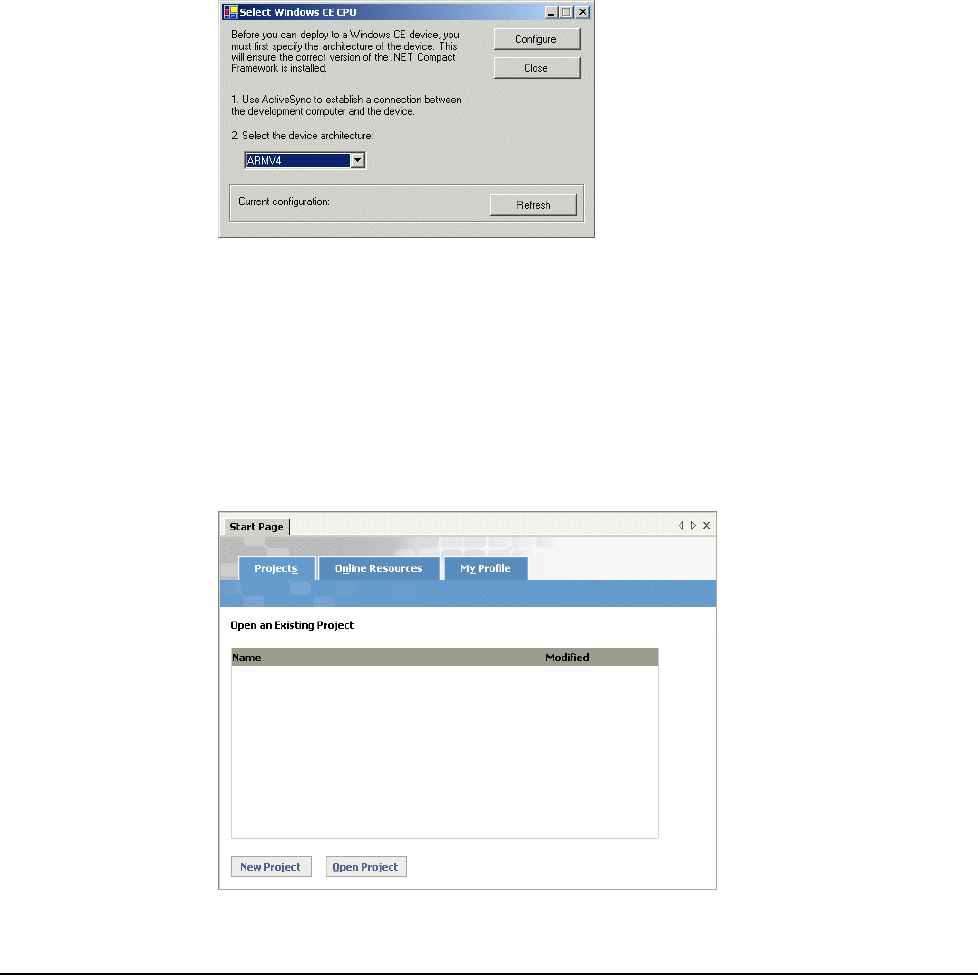
Getting Started with Visual Studio .NET
The section will help you become familiar JETT•RFID application development using Visual Studio
.NET 2003. Procedures in this section include creating a “Hello World” application, deploying the
application and creating a redistributable CAB file. For more information about using Visual Studio
.NET, refer to its online help.
Preliminary Setup
Before using Visual Studio .NET 2003 to create a “Hello World” project for the JETT•RFID, you must
assign a device CPU.
To assign a device CPU:
1. Using ActiveSync, establish communication with the JETT•RFID.
2. Start Visual Studio .NET 2003.
3. On the Tools menu, click Select Windows CE Device CPU. The Select Windows CE Device
CPU dialog box opens.
4. Select ARMV4 as the device architecture from the drop-down box and click Configure.
5. Click Close and exit Visual Studio .NET.
Creating a “Hello World” Application
After restarting Visual Studio .NET, you will be able to create, debug and deploy managed code
applications for the JETT•RFID.
To create a “Hello World” project in Visual Basic .NET:
1. Restart Visual Studio .NET 2003.
2. From the File menu, select New, and then click Project.
3. Click New Project. The New Project Dialog box opens.
Application Development
5
-4
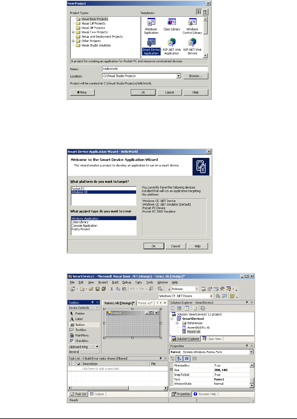
4. Under Project Types, select Visual Basic Projects.
5. Under Templates, select Smart Device Application.
6. Type the Name (such as HelloWorld) and then select the Location of the project (such as
C:\Visual Studio Projects).
7. Click OK. The Smart Device Application Wizard opens.
8. Select Windows CE as the target platform, Windows Application as the project type and then
click OK. You are now ready to begin application development.
JETT•RFID Technical Reference Manual, MAN0339, Rev. A, Preliminary
5
-5
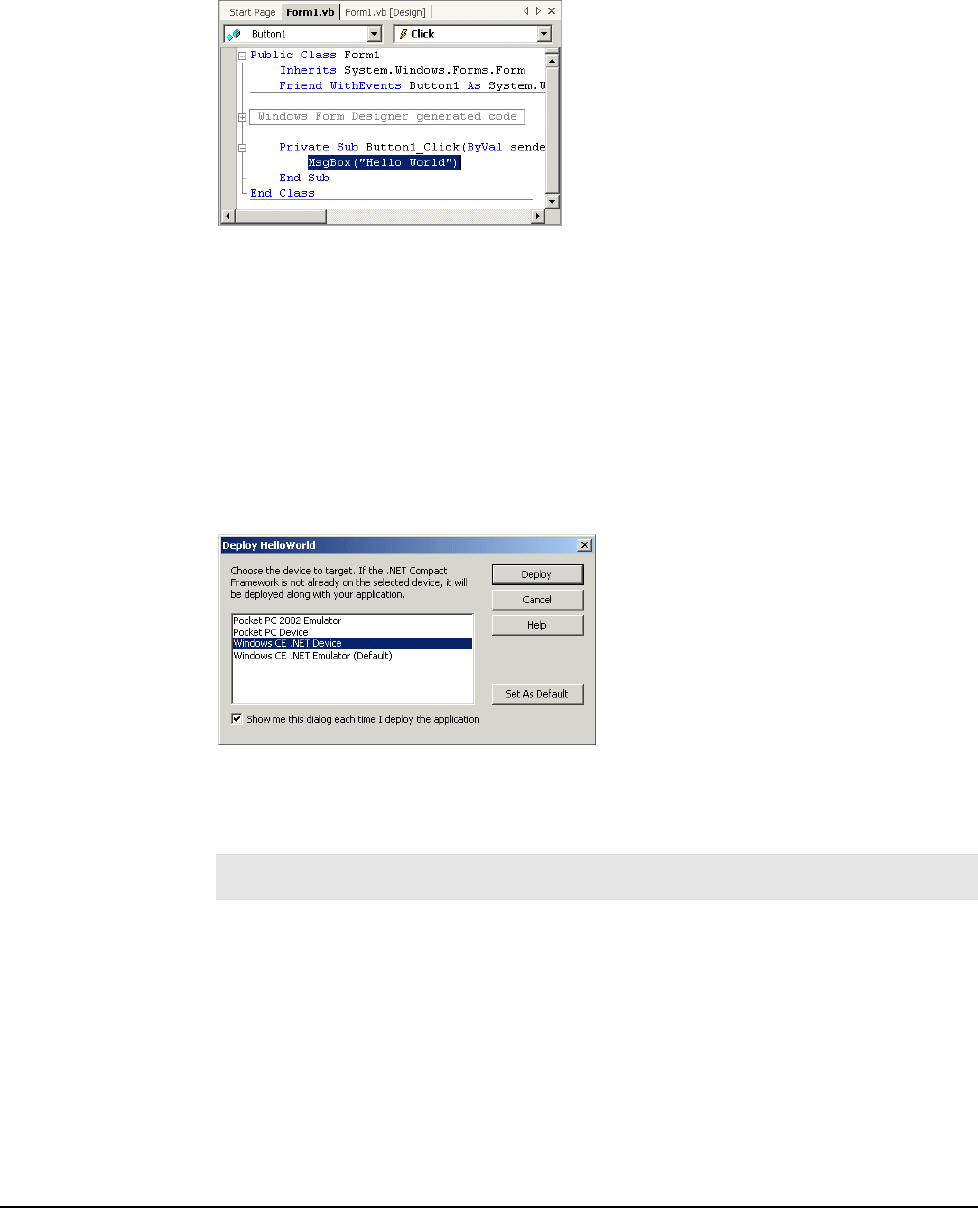
9. To ensure that the form fits on the JETT•RFID, change the Size in the Form1 properties to
200,100. Also, change the Text to “Hello World.”
10. Using the Toolbox (selected from the View menu), place a button on the form and then double-
click the button to open the code window.
11. Enter the following line of code in the button’s Click event handler:
MsgBox(“Hello World”)
Building and Deploying the Application
Before building your application, you must select a configuration type (Debug or Release). A Debug
configuration will compile with full symbolic debug information, but no optimization. A Release
configuration with compile with full optimization, but contain no symbolic debug information.
To build and deploy the application to the JETT•RFID:
1. On the Standard toolbar, choose Release from the Solution Configurations list box.
2. From the Build menu, select Build HelloWorld. Visual Studio .NET will then build the
HelloWorld application. Review the Output panel to make sure the build succeeded without
any errors. You are now ready for deployment.
3. From the Build menu, select Deploy HelloWorld. The HelloWorld dialog box opens.
4. Choose Windows CE .NET Device as the target smart device and then click Deploy to start
the deployment process. Visual Studio .NET will then communicate with the JETT•RFID,
create a HelloWorld folder under “\Program Files” and install the HelloWorld application
there.
Note: To store the files permanently, you can either copy the files to internal compact flash (the
SystemCF folder) to a memory card.
5. To run the HelloWorld application on the JETT•RFID, select Programs from the Start menu
and tap HelloWorld, then click the button on the form to display “Hello Word.”
Application Development
5
-6
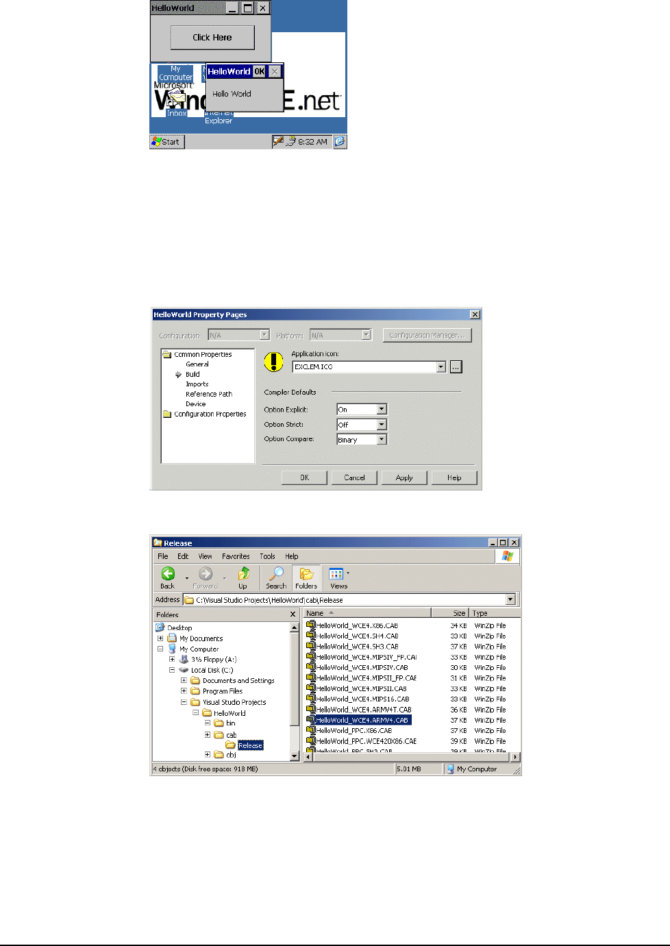
Creating a Redistributable CAB File
To create a redistributable CAB file for the JETT•RFID:
1. From the Project menu, select Properties. In the Common Properties node, select Build.
2. Use the Browse button to locate an icon (.ICO file). By default, icon files are installed in the
“C:\Program Files\Microsoft Visual Studio.NET 2003\Common7\ Graphics\icons” folder.
In this example, choose exclem.ico from the “Misc” subdirectory and click OK. Visual Studio
.NET will then add the icon to the project files and set the icon file’s Build Action to Content.
3. From the Build menu, choose Build Cab File. This action creates CAB files in your project’s
“\cab\Release” folder for all supported hardware platforms.
4. Using ActiveSync, copy the HelloWorld_WCE4.ARMV4.CAB to the Temp folder on the
JETT•RFID. Refer to the “Using ActiveSync” section for details.
5. After you transfer the CAB file, simply tap it to perform the installation.
JETT•RFID Technical Reference Manual, MAN0339, Rev. A, Preliminary
5
-7

By default, the CAB file installation program will automatically attempt to install the
HelloWorld application and related files in a folder under “\Program Files,” but this action
will only store the files temporarily in the unit’s DRAM (i.e., if you turn the power off, the
application files will be lost). To store the files permanently, you can either copy the files to
internal compact flash (the SystemCF folder) to a memory card.
6. To run the HelloWorld application on the JETT•RFID, select Programs from the Start menu
and tap HelloWorld.
Application Development
5
-8

Using eMbedded Visual C++ 4.0
eMbedded Visual C++ 4.0 is a standalone integrated development environment (IDE) designed for
developing applications for JETT•RFID. It consists of an integrated set of windows, tools, menus,
toolbars, directories, and other elements to help create, test, and debug a Windows CE application.
As of this writing, eMbedded Visual C++4.0, this program and its subsequent service patches are
available for download on Microsoft’s website.
Migrating Previous Versions of eMbedded Visual Tools
Windows CE .NET 4.2 does not support the use of eMbedded Visual Tools 3.0.
If you want to continue developing applications in Visual Basic, you will be able to use Visual Studio
.NET, but you will not be able to directly migrate your existing applications to Visual Basic .NET.
However, Visual Basic .NET does includes an Upgrade Wizard for migrating Visual Basic 6.0
application and some portion of your eMbedded Visual Basic applications will be able to take
advantage of this feature. You can find additional information on the MSDN Web site.
Developers using eMbedded Visual C++ 3.0 can rebuild their application in eMbedded Visual C++ 4.0.
System Requirements
To use eMbedded Visual C++ 4.0, your development system must meet the following minimum
requirements:
Processor 450 MHz Pentium II
Operating Systems Windows 2000 Server, Windows 2000 Professional (SP2 or later) or
Windows XP Professional
Memory Windows 2000 Professional & Windows XP Professional: 96 MB RAM
Windows 2000 Server: 192 MB RAM
Disk Space 200 MB
Drive CD-ROM
Display VGA or higher-resolution monitor
Mouse Mouse or compatible pointing device
JETT•RFID Technical Reference Manual, MAN0339, Rev. A, Preliminary
5
-9
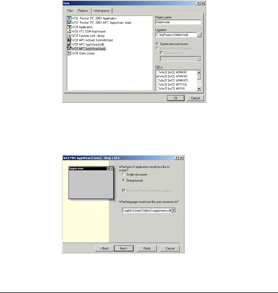
Getting Started with eMbedded Visual C++ 4.0
The section will help you become familiar with JETT•RFID application development using eMbedded
Visual C++ 4.0. Procedures in this section include creating a “Hello World” application, deploying the
application and creating a redistributable CAB file. For more information about using eMbedded Visual
C++ 4.0, refer to its online help.
Creating a “Hello World” Application
To create a “Hello World” project:
1. Using ActiveSync, establish communication with the JETT•RFID.
2. Start eMbedded Visual C++ 4.0.
3. From the File menu, select New. The New dialog box opens.
4. In the New dialog box :
Type in the Project Name and select a location.
Under Projects, select WCE MFC AppWizard (exe).
Under CPUs, check Win32 (WCE ARMV4I).
5. Click OK. The WCE MFC AppWizard (exe) dialog box opens.
6. Click Dialog based and then click Finish. The New Project information dialog box opens.
Application Development
5
-10
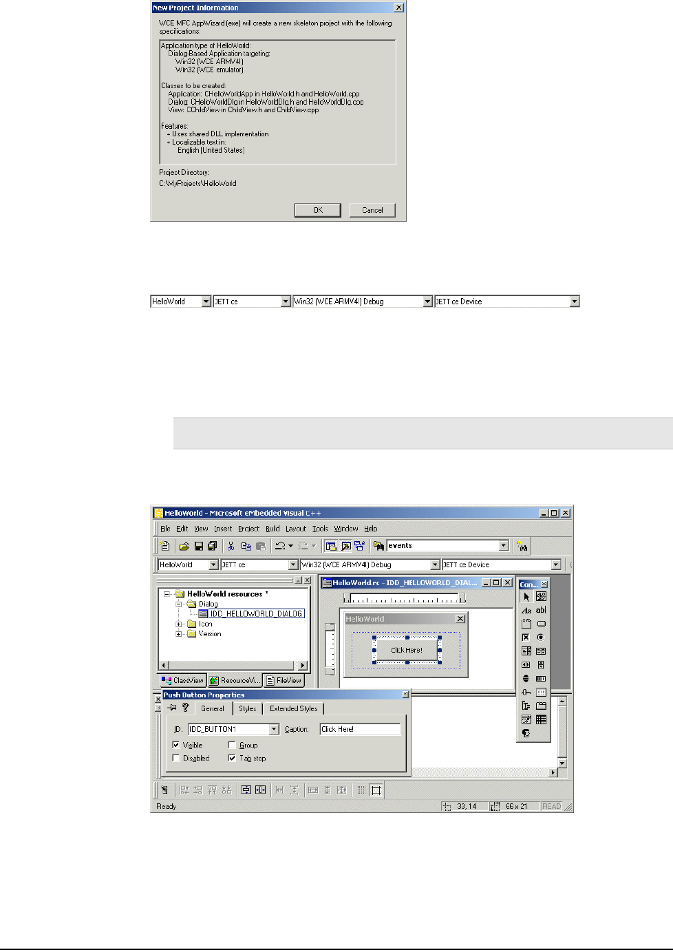
7. Click OK to close. The HelloWorld workspace opens in the upper left pane.
8. On the WCE Configuration toolbar, select JETT ce for the Active WCE Configuration, Win32
(WCE ARMV4I) Debug for the Active Configuration and JETT ce Device as the device type.
9. Add a button to the form:
In the HelloWorld workspace, click the Resources tab, expand the Dialog folder and then
double-click IDD_HELLWORLD_DIALOG. The HelloWorld form opens in the adjoining
pane.
From the Controls toolbar, drag a button onto the form.
Note: If the Controls toolbar does not appear, you can activate it by right clicking the WCE
Configuration toolbar
Right-click the button, select Properties. The Push Button Properties dialog box opens.
Change the caption to “Click Here!” and close the dialog box.
10. Double-click the button. The Add Member Function dialog box opens.
JETT•RFID Technical Reference Manual, MAN0339, Rev. A, Preliminary
5
-11
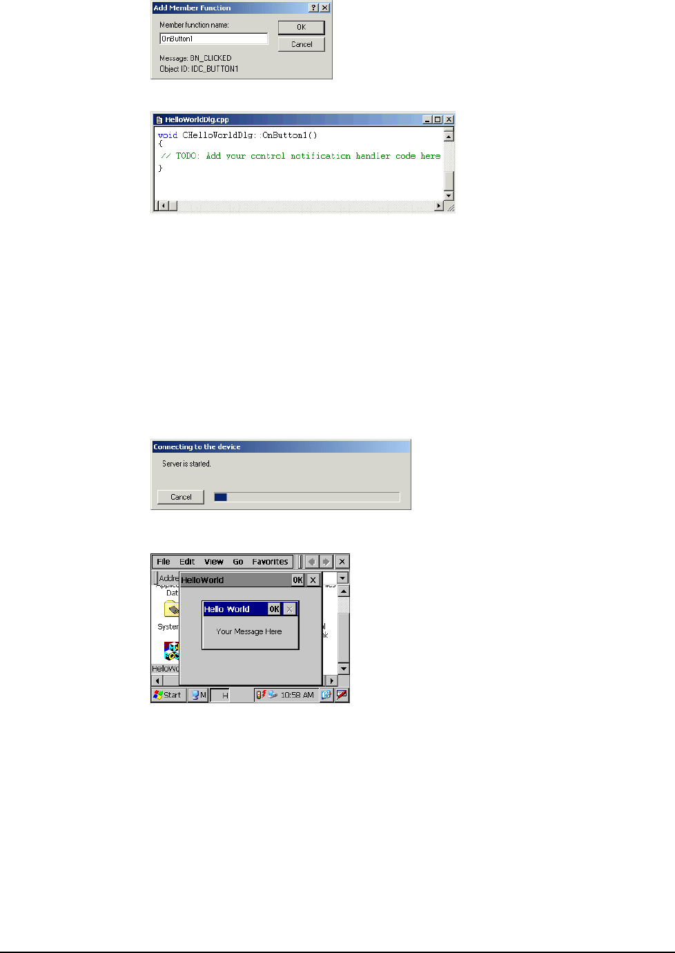
11. Click OK to add the member function. HelloWorldDlg.cpp opens in a new window.
12. Replace the text:
// TODO: Add your control notification handler code here
with the text:
MessageBox (TEXT (“ Your Message Here “), TEXT(“Hello World”), MB_OK);
Building and Deploying the Application
To build and deploy the application to the JETT•RFID:
1. From the Build Menu, select Build HelloWorld.exe.
2. eMbedded Visual C++ 4.0 will then compile the program and attempt communication via
ActiveSync with the JETT•RFID to download the application. After the transfer completes,
you can then run the application on the JETT•RFID.
3. On the JETT•RFID, navigate to the My Computer folder and double-tap the HelloWorld icon
to run the application.
4. Tap Click Here on the form to display “Hello Word.” Tap OK to close
Storing the Application Files”
When eMbedded Visual C++ 4.0 deploys the HelloWorld application to the JETT•RFID, it also copies
the Mfcce400d.dll file to the \Windows folder. Both files are temporarily stored in the unit’s DRAM.
As long as the JETT•RFID remains powered on, you will be able to execute the HelloWorld application.
If you turn the power off, the application files will be lost.
To store the files permanently, you can either copy the files to internal compact flash (i.e., the SystemCF
folder) or to a memory card.
Application Development
5
-12
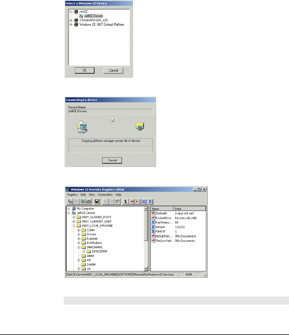
Using the Windows CE .NET Remote Registry Editor
By installing Microsoft eMbedded C++ 4.0, you can view or edit the Windows CE .NET Registry on the
JETT•RFID. If you make any changes, you must invoke the Save Registry command to store the
changes on the JETT•RFID.
To use the Windows CE .NET Remote Registry Editor:
1. If needed, establish an ActiveSync connection.
2. From the Tools menu in eMbedded C++ 4.0, select Remote Tools and choose Registry Editor.
The Select a Windows CE Device dialog box opens.
3. Under JettCE, select JettCE Device and click OK. eMbedded C++ 4.0 will then attempt to copy
the necessary files to the JETT•RFID to view the registry.
4. After the file transfer successfully completes, the JETT•RFID registry should appear in
Windows CE .NET Remote Registry Editor.
5. To change a registry value, double-click the value that you want to change. To add or delete a
registry value, use the Edit menu.
Warning! Changing the registry values on the JETT•RFID can adversely effect its performance.
6. After making your changes, perform a Save Registry on the JETT•RFID.
JETT•RFID Technical Reference Manual, MAN0339, Rev. A, Preliminary
5
-13

Integrating JETT•RFID Functionality
Keyboard Mapping
JETTkbtool.exe, designed to run on your development system, is a command line utility that creates a
key map file. This key map file, when included as part of the FileCopy.txt file, will remap the current
JETT•RFID keypad configuration externally (outside of an application), when the unit boots up.
During the boot sequence, the JETT•RFID searches in ascending alphanumeric order for existing key
map files (identified by their .rmt extension). When the JETT•RFID encounters a files of this type, it
checks the key map ID number. If the ID number contained in the key map file matches the number
stored in the JETT•RFID’s hardware configuration block, the values in that file are used to map to the
keypad.
A 45-key and 55-key keypad template file (Jet55key.txt) and a 15-key keypad (Jet15key.txt) template file
are included with the JETT•RFID SDK. A sample file appears on the following page.
Syntax
JETTKBTOOL filename.ext
Option Description
filename.ext Specifies the name of the file containing the keypad template. The file name must
follow MS-DOS 8.3 naming conventions.
Default file names: 45-key keypad = Jet55key.txt, 15-key keypad = Jet15key.txt
Example
The following example executes JETTKBTOOL using Jet55key.txt as it argument to create the file,
Jet55key.rmt.
JETTKBTOOL Jett55key.txt
Errors Messages
Message Description
Unable to open filename.ext. JETTKBTOOL cannot find the specified file. The
specified file is named incorrectly
Unable to parse to scan code ‘XXX’ on
NNN
The entry (XXX) is not a valid keyword on the specified
line (NNN)
Invalid line NNN The entry specified on line NNN is either misspelled,
not allowed or not formatted correctly
Key Map Template File Configuration Notes
Scan codes “USER_DEF1” through “USER_DEF10” can produce some proprietary action, such as
backlight adjustment, display rotation, etc. For each user-defined key-function (except as noted below),
you must supply the appropriate code in the keyboard driver to produce the desired effect.
“USER_DEF3” defines the Backlight + key and “USER_DEF4” defines the Backlight – key.
The “FUNCTION” keyword identifies those function accessed through the “2nd” key. The “RETURN”
keyword identifies the “ENTER” key. The “WINMENU” keyword produces the Windows “Start”
menu.
The number in COLS must always be set to 5 regardless of the actual number of columns (applies to 15-
key keypads as well).
Do not change the ID number, it must match the number stored in the JETT•RFID’s hardware
configuration block.
Table 5-1 lists the allowable values and names of allowable values that you can map to a keypad.
Application Development
5
-14

# 55 Key JettCE keyboard for P/N 11406 Rev A. keypad
# The keyword “FUNCTION” is used for the “2nd” key.
# The keyword “RETURN” is used for the “ENTER” key.
# “USER_DEF3” defines the Backlight-INCREASE key
# “USER_DEF4” defines the Backlight-DECREASE key
# “WINMENU” produces the Windows “Start” menu.
# COLS must always be set to 5 regardless of
# actual number of columns ROWS 11
COLS 5
# The id of the keyboard.
ID 55
# The basic scan codes.
# row, col Scan Code
SCANCODE 0, 0 -> A
SCANCODE 0, 1 -> B
SCANCODE 0, 2 -> C
SCANCODE 0, 3 -> D
SCANCODE 1, 0 -> E
SCANCODE 1, 1 -> F
SCANCODE 1, 2 -> G
SCANCODE 1, 3 -> H
SCANCODE 2, 0 -> I
SCANCODE 2, 1 -> J
SCANCODE 2, 2 -> K
SCANCODE 2, 3 -> L
SCANCODE 3, 0 -> M
SCANCODE 3, 1 -> N
SCANCODE 3, 2 -> O
SCANCODE 3, 3 -> P
SCANCODE 4, 0 -> Q
SCANCODE 4, 1 -> R
SCANCODE 4, 2 -> S
SCANCODE 4, 3 -> T
SCANCODE 5, 0 -> U
SCANCODE 5, 1 -> V
SCANCODE 5, 2 -> W
SCANCODE 5, 3 -> X
SCANCODE 6, 0 -> Y
SCANCODE 6, 1 -> KEY7
SCANCODE 6, 2 -> KEY8
SCANCODE 6, 3 -> KEY9
SCANCODE 7, 0 -> Z
SCANCODE 7, 1 -> KEY4
SCANCODE 7, 2 -> KEY5
SCANCODE 7, 3 -> KEY6
SCANCODE 8, 0 -> PERIOD
SCANCODE 8, 1 -> KEY1
SCANCODE 8, 2 -> KEY2
SCANCODE 8, 3 -> KEY3
SCANCODE 9, 0 -> BACKSPACE
SCANCODE 9, 1 -> SPACE
SCANCODE 9, 2 -> KEY0
SCANCODE 9, 3 -> RETURN
SCANCODE 10, 0 -> SHIFT
SCANCODE 10, 1 -> FUNCTION
SCANCODE 10, 2 -> CONTROL
SCANCODE 10, 3 -> ALT
SCANCODE 10, 4 -> ESCAPE
JETT•RFID Technical Reference Manual, MAN0339, Rev. A, Preliminary
5
-15

# Table 0 is always the unshifted values.
TABLE 0, basic, UNSHIFTED
TABLE 1, func, FUNCTION
TABLE 2, shift, SHIFT
# Func remapping table.
REMAPPING func, A -> DELETE
REMAPPING func, B -> PAGEUP
REMAPPING func, C -> PAGEDOWN
REMAPPING func, D -> INSERT
REMAPPING func, E -> CAPSLOCK
REMAPPING func, F -> HOME
REMAPPING func, G -> CLEAR
REMAPPING func, H -> SCROLL
REMAPPING func, I -> {
REMAPPING func, J -> TILDA
REMAPPING func, K -> PAUSE
REMAPPING func, L -> }
REMAPPING func, M -> BACKTAB
REMAPPING func, N -> CARET
REMAPPING func, O -> COLON
REMAPPING func, P -> TAB
REMAPPING func, Q -> USER_DEF2
REMAPPING func, R -> PIPE
REMAPPING func, S -> HASH
REMAPPING func, T -> USER_DEF1
REMAPPING func, U -> USER_DEF4
REMAPPING func, V -> COMMA
REMAPPING func, W -> TILDA
REMAPPING func, X -> USER_DEF3
REMAPPING func, Y -> F11
REMAPPING func, Z -> F12
REMAPPING func, PERIOD -> BACKSLASH
REMAPPING func, KEY7 -> F7
REMAPPING func, KEY8 -> F8
REMAPPING func, KEY9 -> F9
REMAPPING func, KEY4 -> F4
REMAPPING func, KEY5 -> F5
REMAPPING func, KEY6 -> F6
REMAPPING func, KEY1 -> F1
REMAPPING func, KEY2 -> F2
REMAPPING func, KEY3 -> F3
REMAPPING func, KEY0 -> F10
# Shift remapping table.
REMAPPING shift, A -> LEFT
REMAPPING shift, B -> UP
REMAPPING shift, C -> DOWN
REMAPPING shift, D -> RIGHT
REMAPPING shift, E -> <
REMAPPING shift, F -> END
REMAPPING shift, G -> UNDERLINE
REMAPPING shift, H -> >
REMAPPING shift, I -> (
REMAPPING shift, J -> EXCLAMATION
REMAPPING shift, K -> SEMICOLON
REMAPPING shift, L -> )
REMAPPING shift, M -> [
REMAPPING shift, N -> QUESTION
REMAPPING shift, O -> QUOTE
REMAPPING shift, P -> ]
REMAPPING shift, Q -> AMPERSAND
REMAPPING shift, R -> AT
Application Development
5
-16

REMAPPING shift, S -> HASH
REMAPPING shift, T -> DOLLAR
REMAPPING shift, U -> SUBTRACT
REMAPPING shift, V -> SLASH
REMAPPING shift, W -> EQUAL
REMAPPING shift, X -> ADD
REMAPPING shift, Y -> PERCENT
REMAPPING shift, Z -> STAR
REMAPPING shift, PERIOD -> DOUBLEQUOTE
#REMAPPING shift, KEY7 ->
#REMAPPING shift, KEY8 ->
#REMAPPING shift, KEY9 ->
#REMAPPING shift, KEY4 ->
#REMAPPING shift, KEY5 ->
#REMAPPING shift, KEY6 ->
#REMAPPING shift, KEY1 ->
#REMAPPING shift, KEY2 ->
#REMAPPING shift, KEY3 ->
#REMAPPING shift, KEY0 ->
Table 5-1: Allowed Values in Key Map Files
A V CARET F9 NUMPAD1 SEMICOLON
B W CLEAR F10 NUMPAD2 SHIFT
C X COLON F11 NUMPAD3 SLASH
D Y COMMA F12 NUMPAD4 SPACE
E Z CONTROL FUNCTION NUMPAD5 STAR
F ( DELETE HASH NUMPAD6 SUBTRACT
G ) DOLLAR HOME NUMPAD7 TAB
H [ DOUBLEQUOTE INSERT NUMPAD8 TILDA
I ] DOWN LEFT NUMPAD9 UNDERLINE
J { END KEY0 PAGEDOWN UP
K } EQUAL KEY1 PAGEUP USER_DEF1
L < ESCAPE KEY2 PAUSE USER_DEF2
M > EXCLAMATION KEY3 PERCENT USER_DEF3
N ADD F1 KEY4 PERIOD USER_DEF4
O ALT F2 KEY5 PIPE USER_DEF5
P AMPERSAND F3 KEY6 PRINT USER_DEF6
Q AT F4 KEY7 QUESTION USER_DEF7
R BACKQUOTE F5 KEY8 QUOTE USER_DEF8
S BACKSLASH F6 KEY9 RETURN USER_DEF9
T BACKSPACE F7 NUMLOCK RIGHT USER_DEF10
U CAPSLOCK F8 NUMPAD0 SCROLL WINMENU
JETT•RFID Technical Reference Manual, MAN0339, Rev. A, Preliminary
5
-17

Generating Audio Tones
The JETT•RFID has a beep driver that you can incorporate into an application for various purposes,
such as notifying an operator that an malfunction occurred or that a process has finished. You can
access the beep driver directly or via Beep.DLL. Parameters that you can define include frequency,
volume and duration (in milliseconds).
Accessing the Beep Driver Directly
The following code snippets (written in eMbedded Visual C++ 4.0) show you how to incorporate beep
driver calls directly into an application
Beep Driver File Structure
The following code shows the file structure used by the beep driver. It also lists the minimum and
maximum allowable values for each parameter.
#ifndef __BEEP_H__
#define __BEEP_H__
typedef struct
{
DWORD dwFrequency; // Frequency
DWORD dwVolume; // Volume
DWORD dwDurationMs; // Beep duration in ms
} BEEP_USER,*PBEEP_USER;
#define FREQUENCY_MIN 56 // Frequency Min
#define FREQUENCY_MAX 20000 // Frequency Max
#define VOLUME_MIN 1 // Normalized Volume Min
#define VOLUME_MAX 100 // Normalized Volume Max
#define DURATIONMS_MIN 0x0 // DurationMs Min
#define DURATIONMS_MAX 10000 // DurationMs Max – 10 secs
BEEP_USER bsBeep;
HANDLE hBEPDevice = NULL;
DWORD dwNumberofBytesRead = 0;
#endif
Creating and Writing to the Beep Driver File
The following code shows how to specify the beep parameters, create a file to store the parameters,
validate that the parameters are within range and then write the values to the file.
If you are generating a series of beeps, you should put a delay of at least one millisecond between each
beep to avoid sound overlap.
bsBeep.dwFrequency = 500;
bsBeep.dwVolume = 20;
bsBeep.dwDurationMs = 1000;
hBEPDevice = CreateFile(L”BEP1:”,
GENERIC_READ | GENERIC_WRITE,
FILE_SHARE_READ | FILE_SHARE_WRITE,
NULL,
OPEN_EXISTING,
FILE_ATTRIBUTE_NORMAL,
NULL);
WriteFile(hBEPDevice,&bsBeep,sizeof(bsBeep),&dwNumberofBytesRead,0);
CloseHandle(hBEPDevice);
Application Development
5
-18

Accessing the Beep Driver via a DLL
The following code snippet (written in Visual Basic .NET) shows you how to incorporate generate
beeps tones into an application using Beep.DLL:
‘ BEEP.dll functions.
‘ Sound the beep.
Private Declare Sub BeepTone Lib “beep” Alias “PlayTone” ( _
ByVal intFrequency As Interger, _
ByVal intVolume As Interger, _
ByVal intDurationMS As Interger, _
)
‘ BeepTone Parameters:
‘ Frequency (KHz) Min – Max 56 to 20000
‘ Normalized Volume Min – Max 1 to 100
‘ Duration (Milliseconds) Min 1 to 10000 (10 sec)
Beeptone (200, 50, 1000)
Miscellaneous Functions
The JETT•RFID has a multifunctional DLL (Jettce.DLL) that allows you to incorporate the following
tasks into an application:
• Turn auxiliary power on and off for internal integrated devices, such as RFID or Bluetooth
cards
• Setting the screen brightness.
Turning Auxiliary Power On and Off
The following code snippet (written in Visual Basic .NET) shows you how to turn on and off auxiliary
power:
‘ Jettce.dll auxiallry power functions.
‘ Turn auxiallry power on.
Private Declare Sub TurnAuxOn Lib “jettce” Alias “TurnAuxSwitchOn” ()
‘ Turn auxiallry power off.
Private Declare Sub TurnAuxOff Lib “jettce” Alias “TurnAuxSwitchOff” ()
Adjusting Screen Brightness
The following code snippet (written in Visual Basic .NET) shows you how to adjust screen brightness in
20 percent increments/decrements:
‘ Jettce.dll screen brightness functions.
‘ Increment screen brightness (+) 20%.
Private Declare Sub IncScreenBrightness Lib “jettce” Alias “IncBrightness” ()
‘ Decrement screen brightness (-) 20%.
Private Declare Sub DecScreenBrightness Lib “jettce” Alias “DecBrightness” ()
JETT•RFID Technical Reference Manual, MAN0339, Rev. A, Preliminary
5
-19
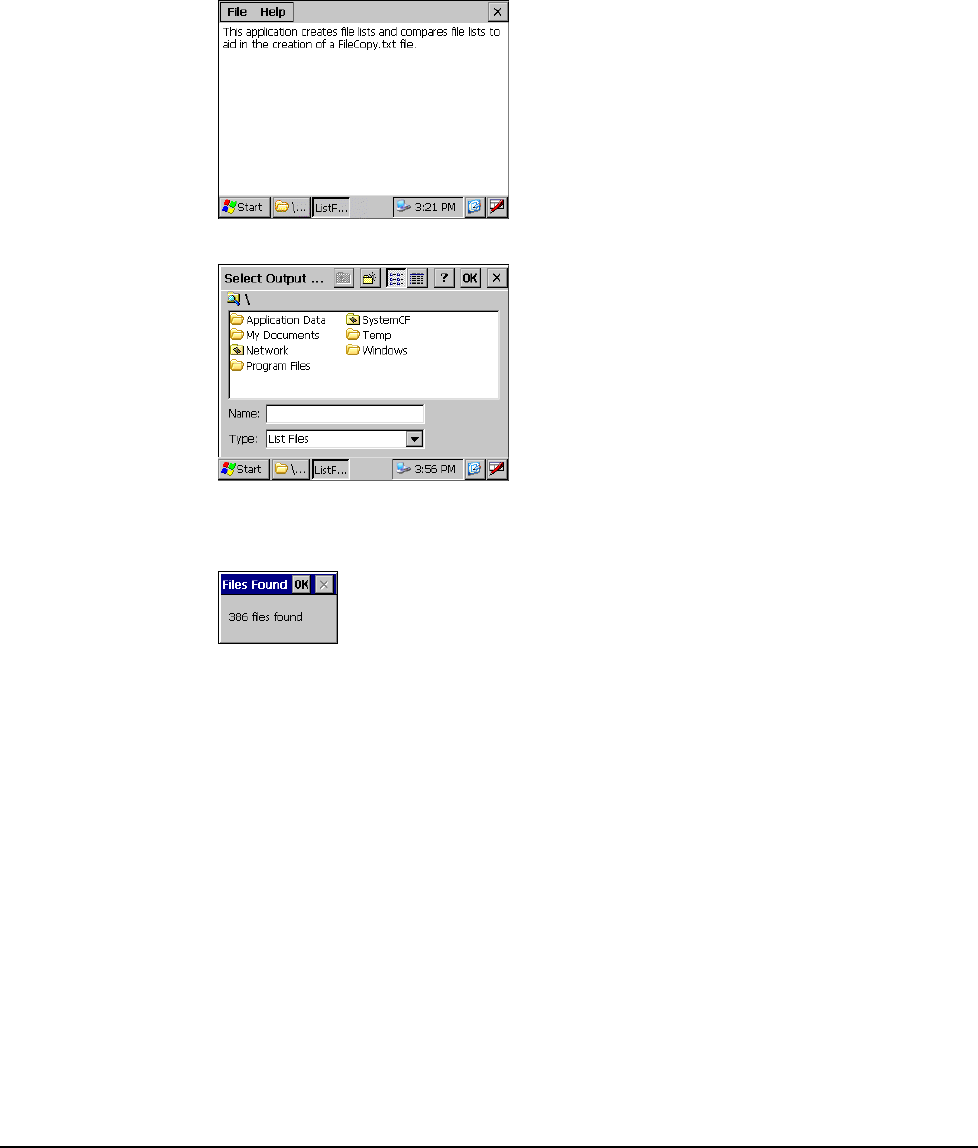
Tracking Self-Installed Files
ListFiles.exe is a utility program that enables you to compare the number of files before and after the
installation of self-extracting software on a JETT•RFID. An output file, which contains the differences,
shows the path and names of the added files, enables you to verify the components of the installed
software as well as their location. You can also incorporate listed in the output file with the contents of
FileCopy.txt to launch the installed software at boot up.
1. On the JETT•RFID, navigate to the Windows folder and double-tap ListFiles.exe. The
ListFiles.exe dialog box appears.
2. On the menu bar, tap File and select New File List. The Select Output File dialog box appears.
3. Enter the name of the output file (such as before.txt) and tap OK (you should copy the file to
either System CF or a compact flash card to permanently store the file).ListFiles.exe will then
display the total number of files found on the JETT•RFID.
4. Tap OK to close the Files Found dialog.
5. Exit ListFiles.exe.
6. Copy and install the new software on the JETT•RFID.
7. After successfully installing the software, restart ListFiles.exe and following Steps 2 through 4
create another output file with a different file name (such as after.txt).
8. On the ListFiles menu bar, tap File and select Compare Lists. The Select Small List dialog box
appears.
9. Navigate to the folder that contains the file created in Steps 2 through 4 (i.e., before.txt), select
it and tap OK. The Select Larger List dialog box appears.
10. Navigate to the folder that contains the file created in Step 7 (i.e., after.txt), select it and tap
OK. The Select Output File dialog box appears.
11. Enter the name of the output file (such as diff.txt) that will contain the list of differences and
tap OK. ListFiles.exe will then display the total number of difference found between the first
and second files.
Application Development
5
-20
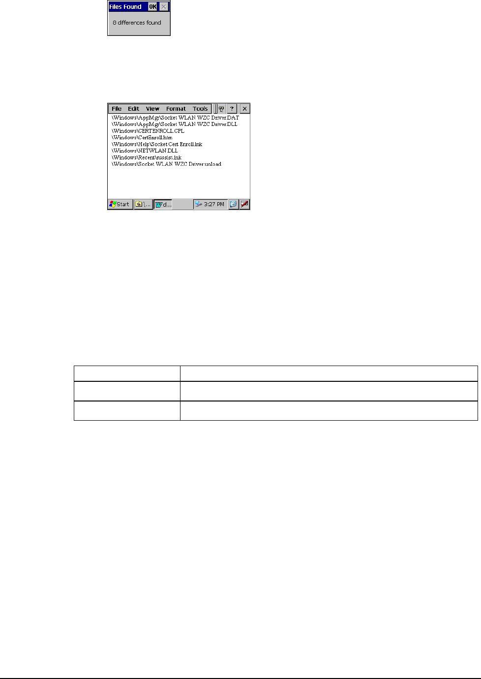
12. Tap OK to close the Files Found dialog.
13. Exit ListFiles.exe.
14. Navigate to the folder that contains the output file (i.e., diff.txt) and double-tap it to view the
contents. For example:
Launching Files at Startup
You can create an ASCII text input file to automatically copy files and create folders when booting up
the JETT•RFID.
During the boot up process, the JETT•RFID looks in the \SystemCF folder for the FileCopy.txt file, and
if found, opens the file and then parses and executes its contents.
When the file copy function executes, it creates the FCLog.txt file in the \SystemCF folder. This log file
will contain any errors encountered during the execution of the FileCopy.txt file.
FileCopy.txt Commands
Each line in the FileCopy.txt file must begin with one of the following command line arguments:
Function Arguments
Copy File copy <\path\source_file> <\path\file_name>
Make Directory md <\path\directory> or mkdir <\path\directory>
If a file or directory name includes one or more spaces, the whole path must appear within quotes. For
example:
copy \systemcf\helloworld.exe “\program files\helloworld.exe”
Example
In the example below, the first line does not require quotes since neither the source path nor the
destination path include a space character. However, the second and third lines do require quotes
because the folder name “My App” contains a space character.
Copy \systemcf\mfcce.dll \windows\mfcce400d.dll
md “\My Apps\”
copy \systemcf\helloworld.exe “\ My Apps\helloworld.exe”
JETT•RFID Technical Reference Manual, MAN0339, Rev. A, Preliminary
5
-21

JETT•RFID Technical Reference Manual, MAN0339, Rev. A, Preliminary
Chapter 6: Troubleshooting
Problem My JETT•RFID does not respond when I press the power button.
Solutions Is the unit in Suspend mode?
If battery-powered, check the batteries.
Are all cables connected properly:
• Is the power supply plugged into an active AC outlet?
• Is the power connector securely plugged into the JETT•RFID?
Problem I changed my system settings, but when I turn on the JETT•RFID my settings are
gone.
Solution You must save the registry after making any system or configuration changes.
Problem I transferred files to the JETT•RFID from my host computer, but when I turn on the
JETT•RFID my transferred files are missing.
Solution To store transferred files permanently, you must file copy the files into internal flash
memory or a compact flash card.
Occasionally, transferred files can be hidden from view, double-tap My Computer,
select Options from the View menu and clear all boxes.
Problem I cannot connect to the development system using ActiveSync.
Solutions Did you install ActiveSync using the Administrator account?
Check the cable connections.
Check the serial communications configuration.
Make sure the correct COM port is available.
In ActiveSync, check the Connection Settings for the connection type you are using
(USB, Serial or Ethernet).
Problem The screen is too light or too dark.
Solution Adjust the brightness via the brightness control in the Control Panel.
6-1

Problem The stylus is not responding properly.
Solution The screen is not calibrated correctly to interpret the screen taps. You need to
recalibrate the screen.
Problem The JETT•RFID acts slowly.
Solutions The unit may be short of program memory or storage memory.
Increase the amount of storage or program memory through the System control in
the Control Panel.
You can also delete any unnecessary files.
Problem I get little or no sound from the JETT•RFID.
Solution Adjust the volume and sound properties via the Volume and Sound control in the
Control Panel.
Problem The JETT•RFID does not recognize a compact flash or device card.
Solution The card is not installed or seated properly.
Reinstall the card. There may be an unstable connection between the card and the
JETT•RFID.
Remove the card, clean the edge connector with a soft dry cloth, and reinstall the
card.
Problem The JETT•RFID goes into auto-suspend after a short period of inactivity.
Solution As a default, the device will auto-suspend after two minutes of inactivity while
running on batteries and after thirty minutes of inactivity when running on AC
power.
Adjust the power management properties via the Power control in the Control
Panel.
Problem No sound is heard when you tap the touch screen or press a key.
Solution Volume setting is low or turned off.
Check the volume slider in the Volume & Sound properties dialog box in the
Control Panel.
Troubleshooting
6-2

JETT•RFID Technical Reference Manual, MAN0339, Rev. A, Preliminary
Appendix A: Specifications
Power
Recharge/Line-Power: 11 to 18 VDC, 1.5A
Battery Type: Nickel Metal Hydride Rechargeable (1400 mAH, 7.2V or 6 AA alkaline batteries
Display
Supertwist Nematic Liquid Crystal TFT with white LED backlight
Resolution: 320 x 240 pixels QVGA color
Touch Screen
Environmental
Operating Temperature: 0°C to +50°C
Storage Temperature: -25°C to +70°C
Charging Temperature: 0°C to + 40°C
Humidity: 5-95% Non-condensing
CPU
Type: Intel PXA255 processor with Xscale technology
Instruction Set Architecture: ARM v.5TE
Speed: 200 MHz (400 MHz optional)
Operating System: Windows CE .NET 4.2 Professional
Memory and Mass Storage
SDRAM: 64MB
Internal Compact Flash: 64 MB standard (16MB reserved for OS), upgradeable to 128MB
Optional: Compact flash card slot
RFID Module
Multi-protocol read/write support for 13.56MHz RFID tag types including ISO-15693, ISO-14443,
Philips Mifare, Tag-It by Texas Instruments, Icode by Philips, my-d from Infineon, LRI512 by ST
Microelectronics, GemWave by TagSys, and PicoTag from Inside Contactless.
Read Range: 3.152-3.546 inches (80-90 mm)
Output Power Measurement: 22.8 dbm = 200 mW
User Input
Touch Screen
Key Pad: 45-Key membrane (9 rows x 5 columns) or 15-key elastomeric (5 x 3)
Feedback: Tactile and audible
Optional: LED backlighting
Indicators
5 Modifier Key/Programmable LEDs
Charge/Low Battery Indicator (battery-powered units only)
A
-1
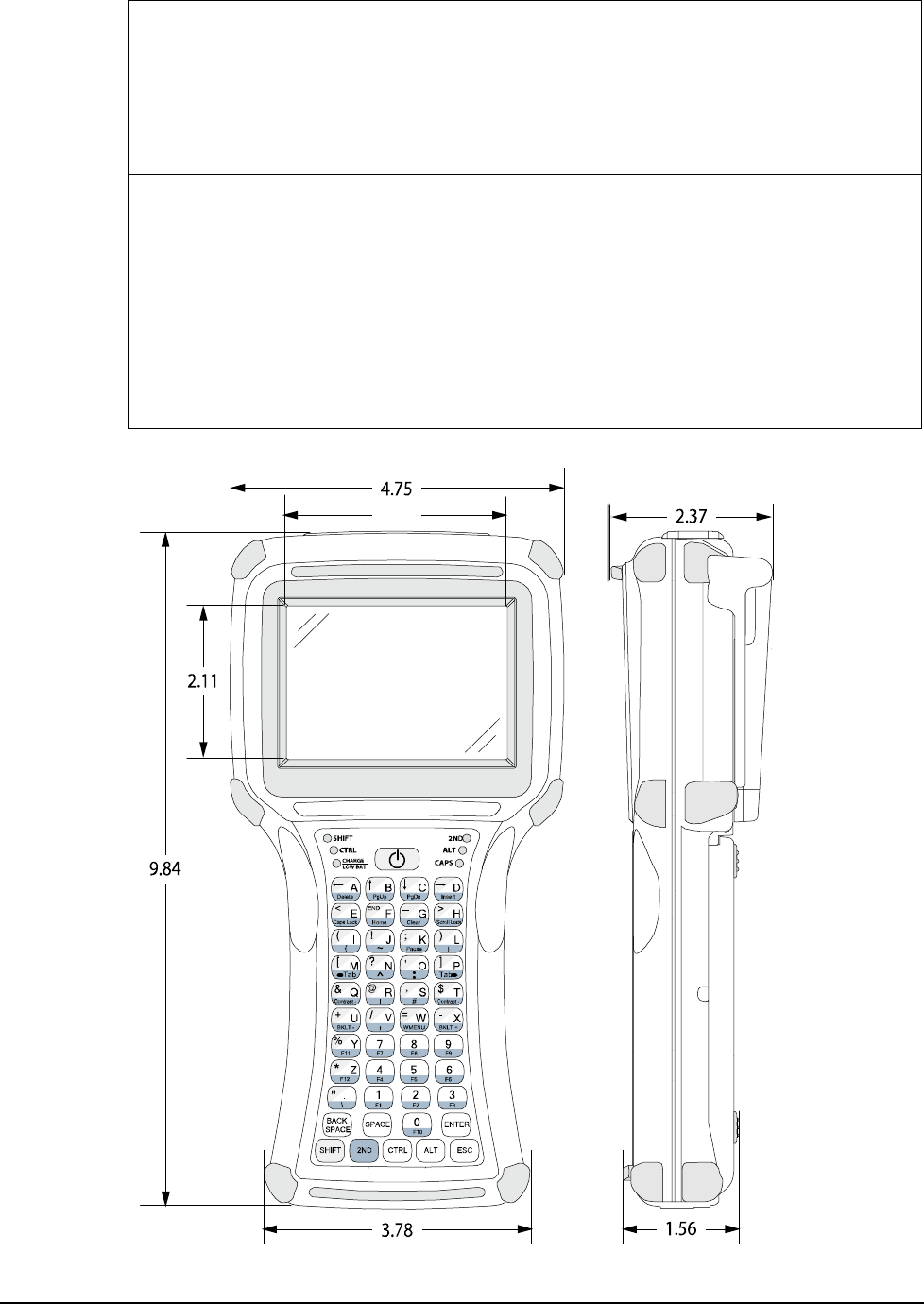
Interface Capability
JETT•connect system interface: Configured as COM1 for RS-232 serial communication. Provides
input power for line-powered units (11–18VDC) and recharging capability for battery-powered
units
Six-Pin Modular Connector: Configured as COM2 for RS-232 serial communication—available for
use when the RFID reader is not active.
Either interface connection can optionally provide output at 5 VDC to operate peripheral device
Physical Dimensions
Height (H): 9.84 Inches (250 mm)
Width (W): 4.75 Inches (120.7 mm)
Depth (D): 2.37 Inches (60.2 mm)
Weight :
• Without Batteries: 27 Ounces (765.4 grams)
• With Alkaline Batteries: 32 Ounces (907.2 grams)
• With NiMH Batteries: 33 Ounces (935.5 grams)
Specifications subject to change
Figure A-1: Case Dimensions
2.82
Troubleshooting
A
-2
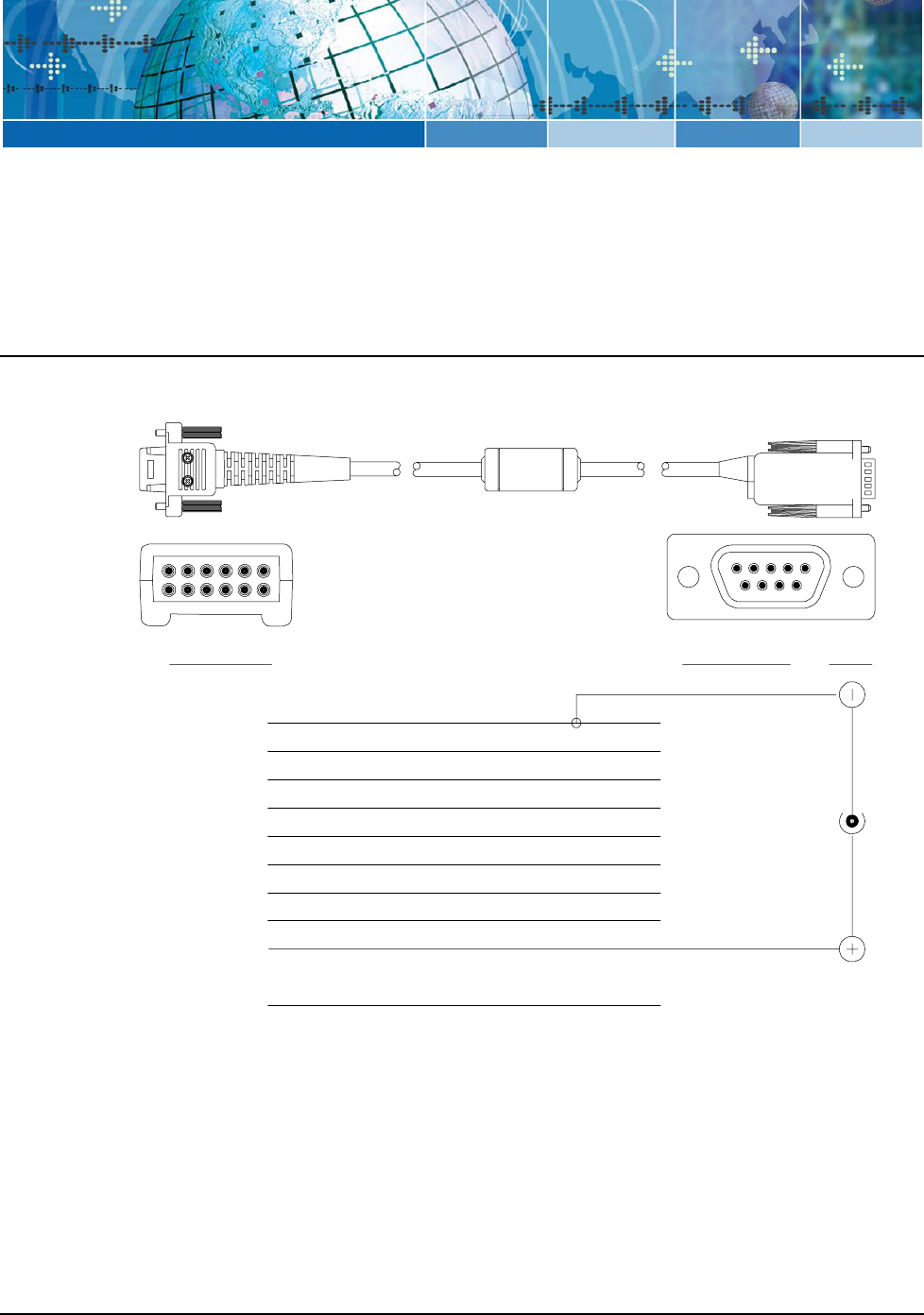
JETT•RFID Technical Reference Manual, MAN0339, Rev. A, Preliminary
Appendix B: Signal and Pin Assignments
JETT•connect Cables
Figures B1 and B2 list the standard RS-232 signal and pin assignments for the JETT•connect cables.
Figure B-1: 91708 Cable (Male DE9) RS-232 Signal and Pin Assignments
JETT• Connect DE 9 Connector
9
8
76
54321
9
8
7
6
5
4
3
2
111
1012
Pin 1 (Reserved)
Pin 2 (GND)
Pin 3 (RI)
Blue
Pin 4 (CTS)
Pin 5 (DTR)
Pin 6 (TXD)
Pin 7 (DSR)
Pin 8 (RTS)
Pin 9 (DCD)
Pin 10 (PWR)
Pin 11 (SHIELD)
Pin 12 (RXD)
Pin 5 (GND)
Pin 9 (RI)
Pin 8 (CTS)
Pin 4 (DTR)
Pin 3 (TXD)
Pin 1 (DCD)
Pin 2 (RXD)
Pin 6 (DSR)
Pin 7 (RTS)
Power
White w/Black Stripe
Gray
Black
Violet
Yellow
Brown
Red
Orange
White
Green
Viewed Facing
Connector
B-1
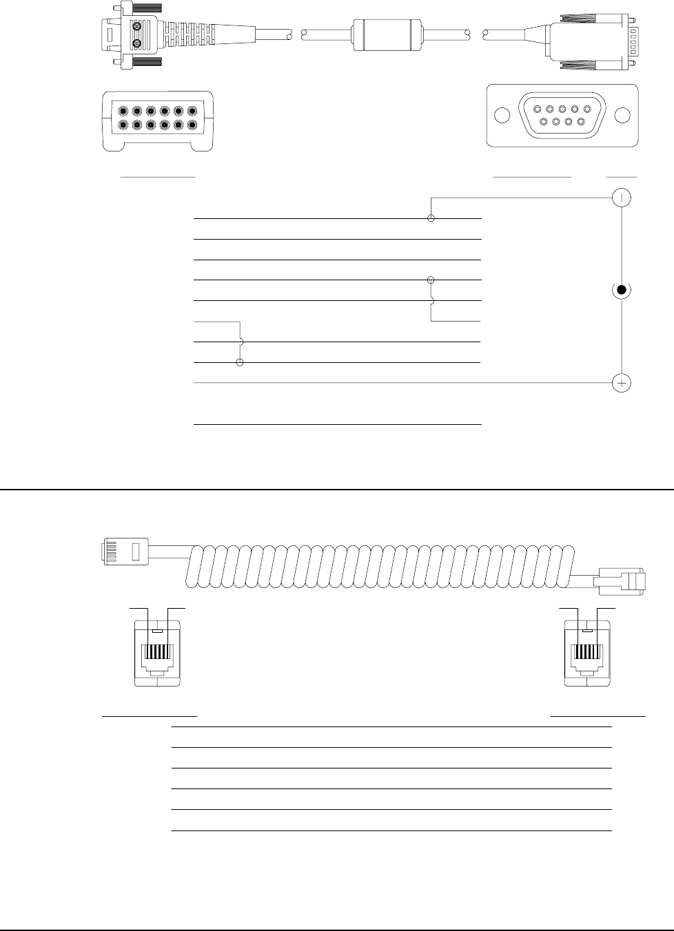
Figure B-2: 91709 Cable (Female DE9) RS-232 Signal and Pin Assignments
JETT• Connect DE 9 Connector
9
8
76
54321
9
8
7
6
5
4
3
2
111
1012
Pin 1 (Reserved)
Pin 2 (GND)
Pin 3 (RI)
Pin 4 (CTS)
Pin 5 (DTR)
Pin 6 (TXD)
Pin 7 (DSR)
Pin 8 (RTS)
Pin 9 (DCD)
Pin 10 (PWR)
Pin 11 (SHIELD)
Pin 12 (RXD)
Pin 5 (GND)
Pin 9 (RI In)
Pin 7 (CTS In)
Pin 1 (DTR Out)
Pin 2 (TXD Out)
Pin 4 (DSR/DCD In)
Pin 3 (RXD In)
Pin 6 (DTR Out)
Pin 8 (RTS Out)
Power
Viewed Facing
Connector
Blue
Gray
Red
Orange
Green
Brown
Black
Violet
White
Yellow
White w\Black Stripe
Violet
1210 Series Modular Interface Cables
Figure B3 lists the signal and pin assignments for 1210 series modular cables.
Figure B-1: 1210 Series Modular Cable Signal and Pin Assignments
6-Pin Modular Jack
Pin 1 (Blue)
Pin 2 (Yellow)
Pin 3 (Green)
Pin 4 (Red)
Pin 5 (Black)
Pin 6 (White)
Pin 6
Pin 5
Pin 4
Pin 3
Pin 2
Pin 1
Pin 6
6-Pin Modular Jack
Pin 6
Pin 1
Pin 1
Troubleshooting
B-2
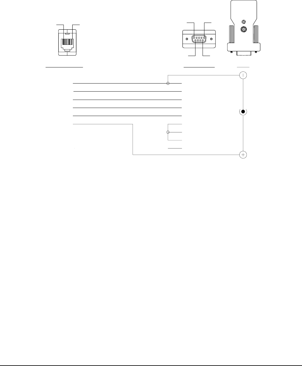
Modular Cable Adapters
Pin descriptions assume connection through reversing cables (1210-7, 1210-15) to JETT•RFID.
CELAT-P Adapter
Figure B4 lists the signal and pin assignments for the CELAT-P adapter.
Figure B-1: CELAT-P Adapter
6-Pin Modular Jack DE 9 Connector
Pin 5 (Ground)
Pin 2 (RXD)
Pin 3 (TXD)
Pin 8 (CTS)
Pin 7 (RTS)
Pin 6 (DSR)
Pin 9 (RI)
Pin 1 (DCD)
Pin 4 (DTR)
Power
Viewed Facing
Connector
Pin 1
Pin 6
Pin 5
Pin 1
Pin 9
Pin 6
Pin 1 (Blue)
Pin 2 (
Pin 3 (
Yellow)
Green)
Pin 4 (Red)
Pin 5 (Black)
Pin 6 (White)
JETT•RFID Technical Reference Manual, MAN0339, Rev. A, Preliminary B-3

JETT•RFID Technical Reference Manual, MAN0339, Rev. A, Preliminary
Index
Changing Batteries ...........................................................3-4
Changing System Settings...............................................4-2
. Charge\Low Battery Indicator.......................................3-3
.NET Compact Framework............................................. 5-2 Charge\Low Battery Indicator Functions.....................3-3
Limitations.................................................................... 5-3 Charging the Unit.............................................................3-4
Supported Languages ................................................. 5-2 CHG Indicator ..................................................................3-3
Compact Flash Slot...........................................................2-3
1 Configuration....................................................................4-1
Connecting to a Mail Server............................................4-4
1210 Series Modular Cable .............................. 2-4, 2-5, B-2 Control Panel ....................................................................4-1
Signal and Pin Assignments.......................................B-2 Control Panel Functions
Backlight........................................................................4-1
2 Battery Status................................................................4-1
2ND Key............................................................................ 3-7 Beep Status....................................................................4-1
Certificates ....................................................................4-1
A Date and Time ..............................................................4-1
Dialing ...........................................................................4-1
About RFID....................................................................... 1-1 Display ..........................................................................4-1
About the JETT•RFID ..................................................... 1-2 Input Panel....................................................................4-1
About this Manual........................................................... 1-1 Internet Options ...........................................................4-1
About Two Technologies................................................ 1-1 Keyboard.......................................................................4-1
ActiveSync ............................................................... 3-11, 5-1 Network and Dial-up Connections............................4-1
Application Development............................................... 5-1 Owner............................................................................4-1
Application Types............................................................ 5-1 Password.......................................................................4-1
Auxiliary Port Cable Connections ................................. 2-5 PC Connections ............................................................4-1
Power.............................................................................4-2
B Regional Settings..........................................................4-2
Remove Programs........................................................4-2
Battery Compartment...................................................... 2-2 Storage Manager ..........................................................4-2
Battery Indicator .............................................................. 2-1 Stylus .............................................................................4-2
Battery Orientation .......................................................... 3-5 System ...........................................................................4-2
Battery-Powered Operation............................................ 3-3 VComAdj ......................................................................4-2
Beep Driver Copy File Command......................................................5-21
Accessing the Beep Driver Directly......................... 5-18 CPU Specifications ..........................................................A-1
Accessing the Beep Driver via a DLL ..................... 5-19 Creating a Network (Ethernet) Connection ..................4-4
Creating and Writing to the Beep Driver File........ 5-18 CTRL and ALT Keys........................................................3-6
File Structure.............................................................. 5-18
D
C
Data Entry .........................................................................3-5
C# .NET............................................................................. 5-2 Desktop Functions............................................................3-9
Cable Connections ........................................................... 2-4 Development Tools ..........................................................5-1
1210 Series Modular Cable ......................................... 2-5 Disconnecting from the Development System ...........3-13
JETT•connect System.................................................. 2-4 Display...............................................................................2-1
Cables and Connections.................................................. 2-4 Display Rotation...............................................................4-1
Case Dimensions............................................................. A-2 Display Specifications.....................................................A-1
CELAT-P Adapter............................................. 2-4, 2-5, B-3
I-1

K
Displays............................................................................. 1-3
Durability.......................................................................... 1-3 Key Map Template File Configuration........................5-14
Keyboard Mapping........................................................5-14
E Keypad...............................................................................2-1
Keypads.............................................................................1-3
eMbedded Visual C++ 4.0 .............................................. 5-1
15-Key............................................................................3-6
Environmental Specifications........................................ A-1
45-Key............................................................................3-5
F L
FileCopy.txt .................................................................... 5-21
Launching Files at Startup ............................................5-21
Front Components and Indicators................................. 2-1
LEDs...................................................................................2-1
Fully/Near Full Charge .................................................. 3-3
Limitations, .NET Compact Framework .......................5-3
ListFiles.exe.....................................................................5-20
G LOW BAT Indicator.........................................................3-3
Generating Audio Tones............................................... 5-18
Getting Started with eMbedded Visual C++ 4.0........ 5-10 M
Building and Deploying the Application............... 5-12
Make Directory Command ...........................................5-21
Creating a Hello World Application....................... 5-10
Managed Code..................................................................5-1
Storing the Application Files.................................... 5-12
Memory and Mass Storage .............................................1-2
Getting Started with Visual Studio .NET...................... 5-4
Memory and Mass Storage Specifications....................A-1
Building and Deploying the Application................. 5-6
Microsoft WordPad..........................................................3-9
Creating a Hello World Application......................... 5-4
Migrating Previous Versions of eMbedded Visual Tools
........................................................................................5-9
Creating a Redistributable CAB File......................... 5-7
Preliminary Setup........................................................ 5-4
Miscellaneous Functions ...............................................5-19
Preliminary Setup........................................................ 5-4
Adjusting Screen Brightness.....................................5-19
Turning Auxiliary Power On and Off..................... 5-19
H Modifier Key Actions.......................................................3-7
High Power Charge......................................................... 3-3 Modifier Keys ...................................................................3-6
Modular Cable Adapters................................................ B-3
I Modular to DE-9S Adapter .............................................2-4
Modular-to-Modular Cable.............................................2-4
IMAP4 ............................................................................... 4-4 My Computer....................................................................3-9
Inbox.................................................................................. 3-9 My Documents .................................................................3-9
Indicator Specifications.................................................. A-1
Indicators .......................................................................... 1-3 N
Initial Communication .................................................. 3-11
Input Panel ....................................................................... 3-7 Native Code ......................................................................5-1
Inserting and Removing Cards.................................... 3-15 Network Connections......................................................4-4
Integrating JETT•ce Functionality............................... 5-14
Interface and Expansion Capabilities............................ 1-3 O
Interface Connections
On/Off Switch..................................................................2-1
Standard RS-232 Pin and Signal Assignments......... 2-3
Operating System.............................................................1-2
Interface Specifications................................................... A-2
Operation...........................................................................3-1
Internet Explorer.............................................................. 3-9
Overview...........................................................................1-1
J P
JETT•ce SDK .................................................................... 5-1
Persistent Registry..........................................................3-14
JETT•connect Cable .................................................2-4, B-1
Physical Dimensions.......................................................A-2
Cable and Power Connections................................... 2-4
POP3...................................................................................4-4
RS-232 Signal and Pin Assignments
Power ..........................................................................1-2, 3-1
Female DE9...............................................................B-2
Male DE9...................................................................B-1 Power Management.........................................................3-3
JETT•connect System...................................................... 2-4 Power Off ..........................................................................3-2
JETT•RFID Components ................................................ 2-1 Power On...........................................................................3-1
JETT•RFID Features........................................................ 1-2 Power Requirements.......................................................A-1
JETTkbtool.exe ........................................................ 5-1, 5-14 Power Status Icons .........................................................3-10
Power Supply....................................................................2-4
Troubleshooting
I-2

T
Power/Suspend Switch .................................................. 3-1
Processor ........................................................................... 1-2 Taskbar ............................................................................3-10
Taskbar and Start Menu Settings....................................4-3
R The Windows CE .NET Desktop....................................3-9
Tracking Self-Installed Files..........................................5-20
Recycle Bin........................................................................ 3-9
Trickle Charge...................................................................3-3
Reset................................................................................... 3-2
Troubleshooting................................................................6-1
Resetting the Registry.................................................... 3-14
RFID Module.................................................................... 2-2 U
RFID Read Range............................................................. 3-8
User Input Specifications................................................A-1
S Using ActiveSync ...........................................................3-11
Using eMbedded Visual C++ 4.0....................................5-9
Saving Changes to the Registry ................................... 3-14
Using the Compact Flash Slot......................................3-15
Setting Up Identification for Remote Networks .......... 4-4
Using the RFID Module...................................................3-8
SHIFT Key......................................................................... 3-6
Using the Windows CE .NET Remote Registry Editor..5-
13
Signal and Pin Assignments...........................................B-1
Specifications................................................................... A-1
Using Visual Studio .NET ...............................................5-2
Start Menu ...................................................................... 3-10
Subsequent Communication ........................................ 3-13 V
Supported Languages, .NET Compact Framework .... 5-2
Suspend Mode.................................................................. 3-2 Visual Basic .NET .............................................................5-2
System Requirements Visual Studio .NET 2003..................................................5-1
eMbedded Visual Tools 4.0........................................ 5-9
Visual Studio .NET...................................................... 5-2 W
Windows CE Utilities for Visual Studio .NET 2003.....5-1
JETT•RFID Technical Reference Manual, MAN0339, Rev. A, Preliminary I-3