Two Technologies JETTRFIDPLUS JETTRFIDPLUS User Manual JETT RFID Technical Reference Manual
Two Technologies, Inc. JETTRFIDPLUS JETT RFID Technical Reference Manual
UserManual.wiki
>
Two Technologies
>
JETTRFIDPLUS User Manual
User Manual
Navigation menu
Upload a User Manual
Namespaces
Wiki Guide
HTML
PDF
Info
Views
User Manual
Discussion / Help
Navigation


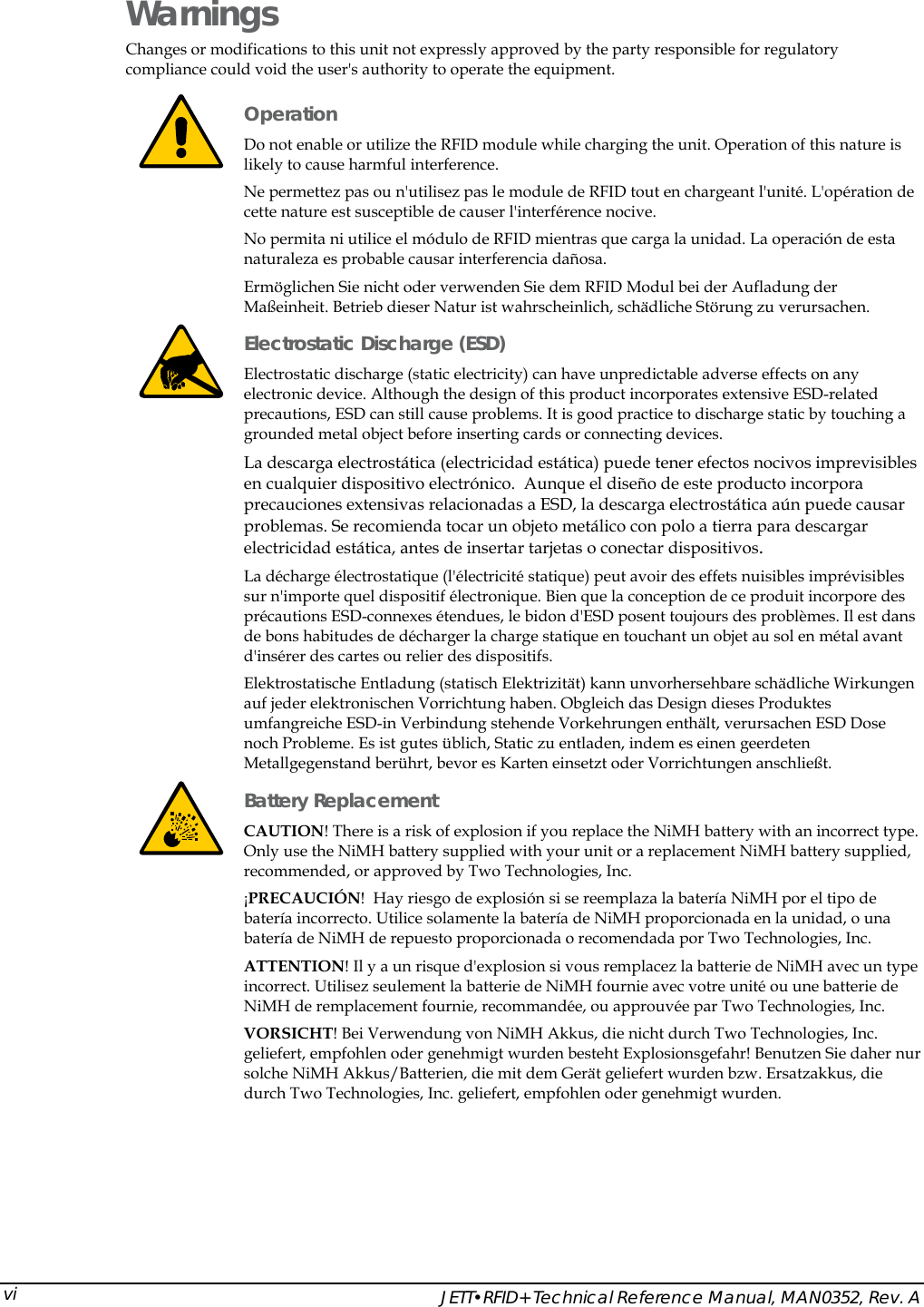
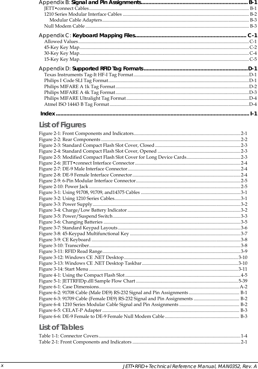
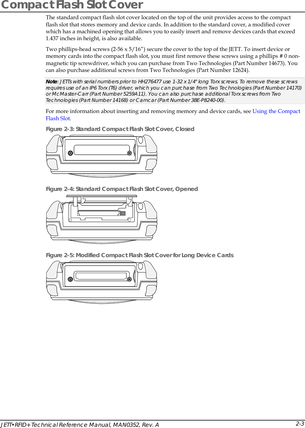

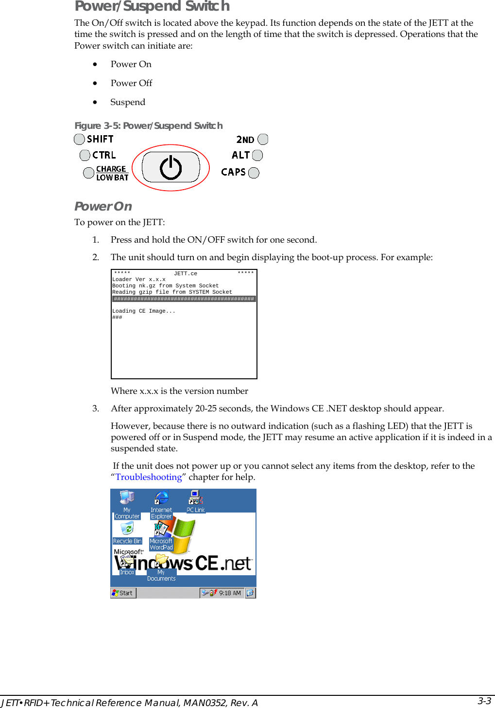

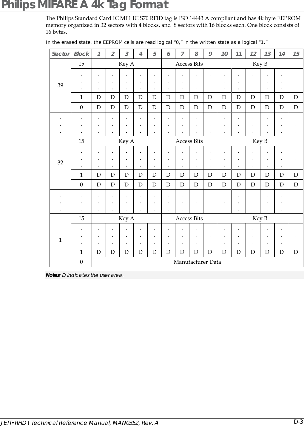
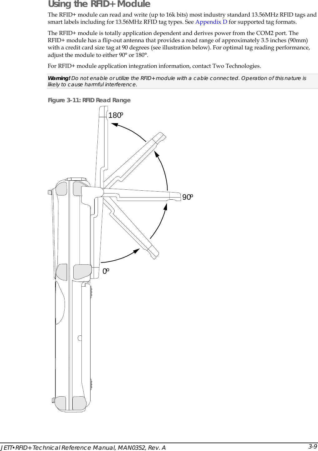
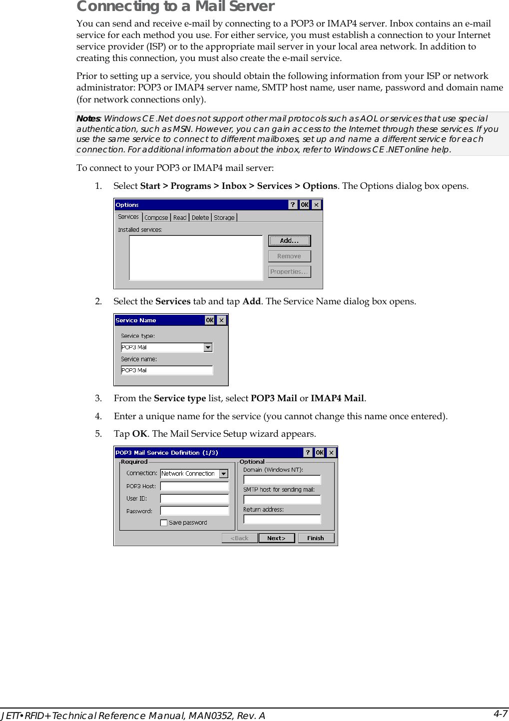
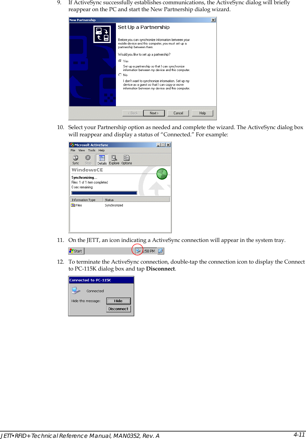
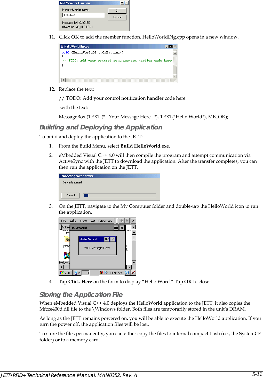
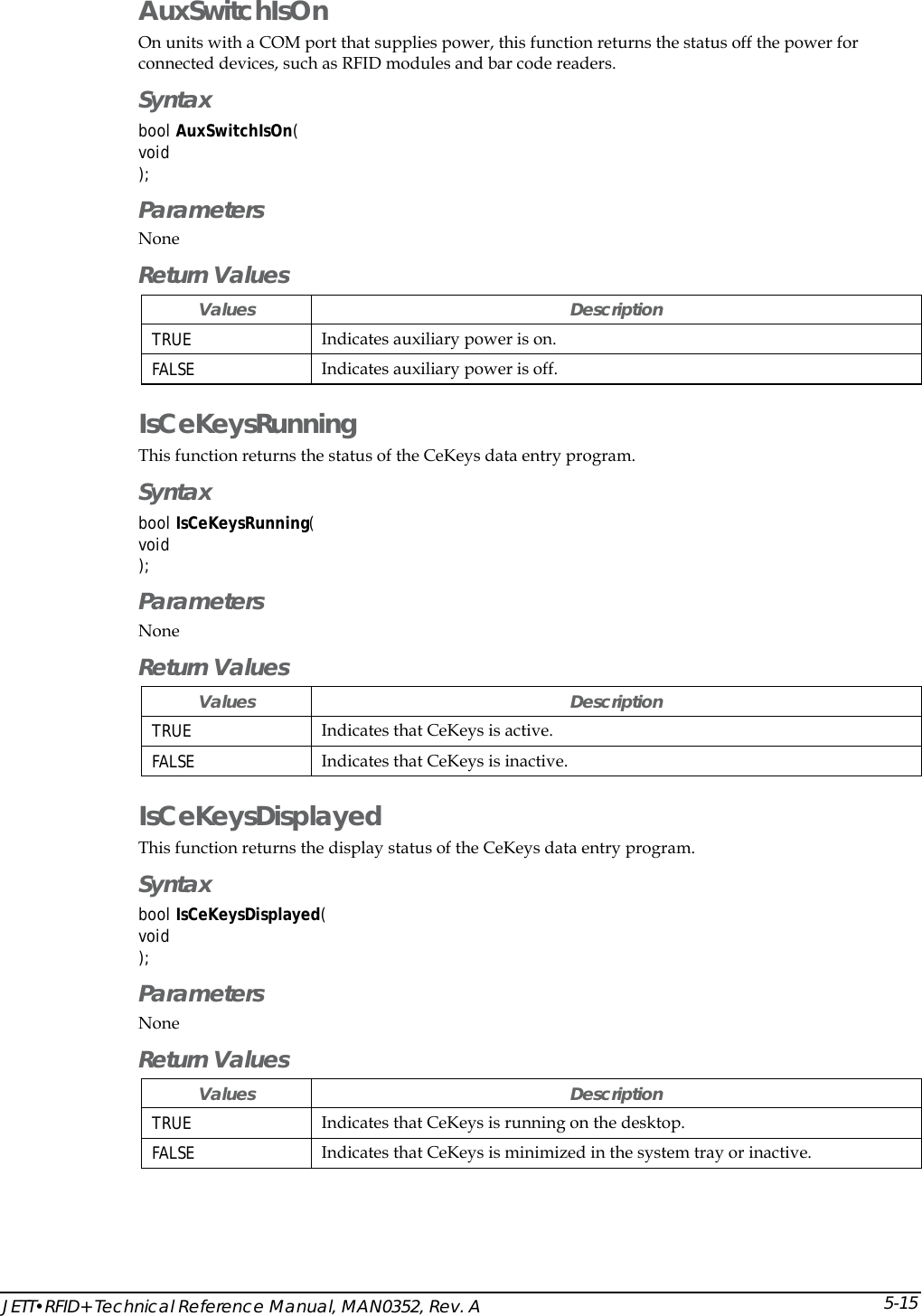
![Operation 3-6Data Entry Keypads 45-Key Keypads In order to provide the functionality of a full-sized keyboard with only 45 keys, the JETT keypad must depart from PC-style key assignment conventions by making use of modifier keys. Units configured with the standard 45-key keypad typically utilize five LED indicators (located above the ON/OFF switch) to indicate the active state of keypad modifier keys. Units with 45-key keypads also have keypad functions to adjust the contrast and backlight. 30-Key Keypad Units with a 30-key keypad provide a full complement of alphabetical characters. Users can access numeric characters, punctuation characters, navigation keys and backlight control via the SHIFT key. 15-Key Keypad Typically, units shipped with a 15-key keypad have custom keyboard layouts geared toward specific applications that must be loaded onto the unit. To provide you a method of navigating and using Windows CE .NET until you configure and map your keypad in the context of your application using Kbtool. Two Technologies provides a template that shows the default functions (see figure below). Figure 3-7: Standard Keypad Layouts GADelete BPgUp CPgDn DInsertE FHome HI{J~KL}<END _>^Pause(!;)[?']RST#Q&@$U+V,/XBKLT +-W=Y%7F79F98F8Z*4F46F65F5.\1F12F23F30F10BACKSPACE SPACE ENTERSHIFT 2ND CTRL ALT ESCBKLT -"ClearOMN PTab Tab,WMENUF11F12| 45-Key Keypad SHIFTALT ESC0BACKSPC SPC ENTER798*465123U+V,/XBKLT +-WBKLT-ZYGABCDEFHIJKL?RSTQOMNPTAB: 30-Key Keypad TAB ALT\-+ESC .ENTER2ND CTRLBackSpaceSPACE 15-Key Keypad](https://usermanual.wiki/Two-Technologies/JETTRFIDPLUS/User-Guide-603360-Page-28.png)
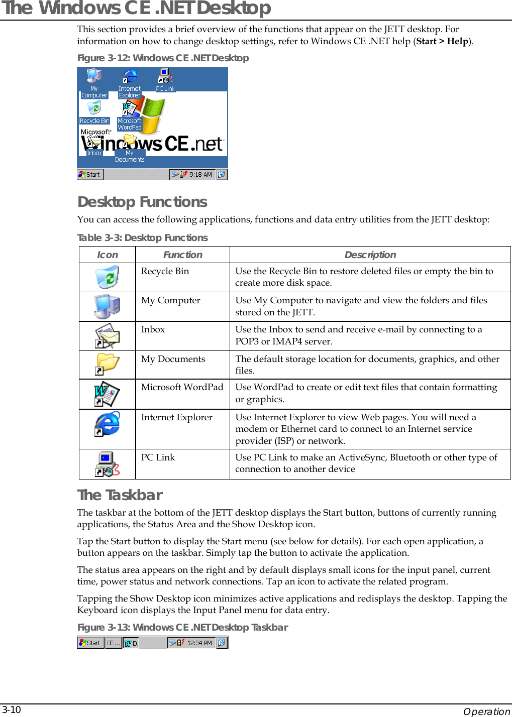

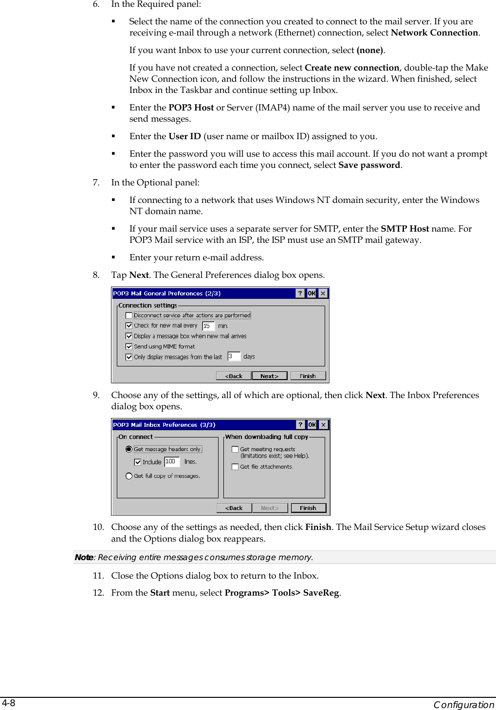
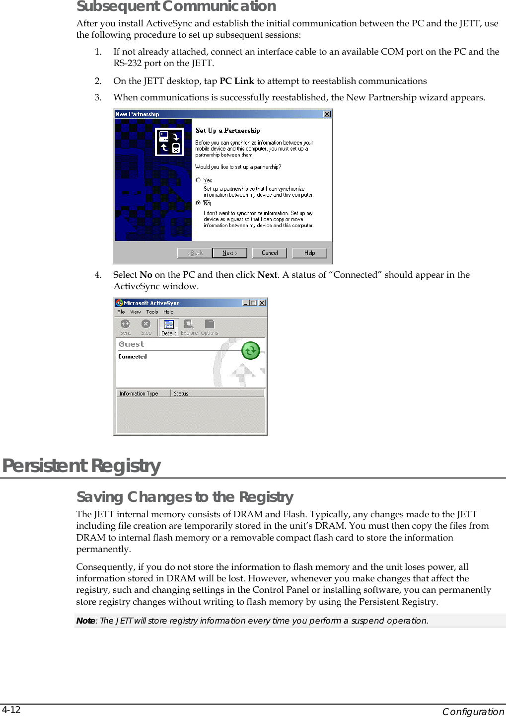


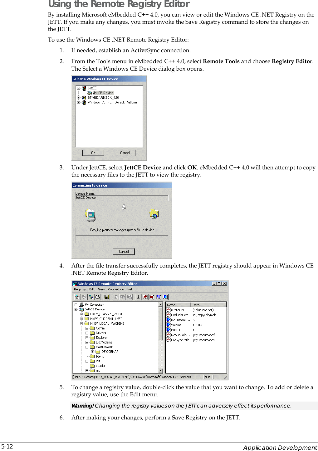
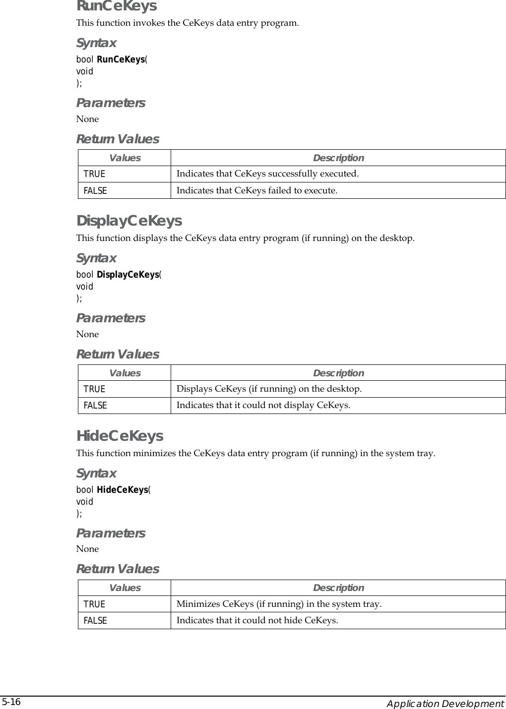
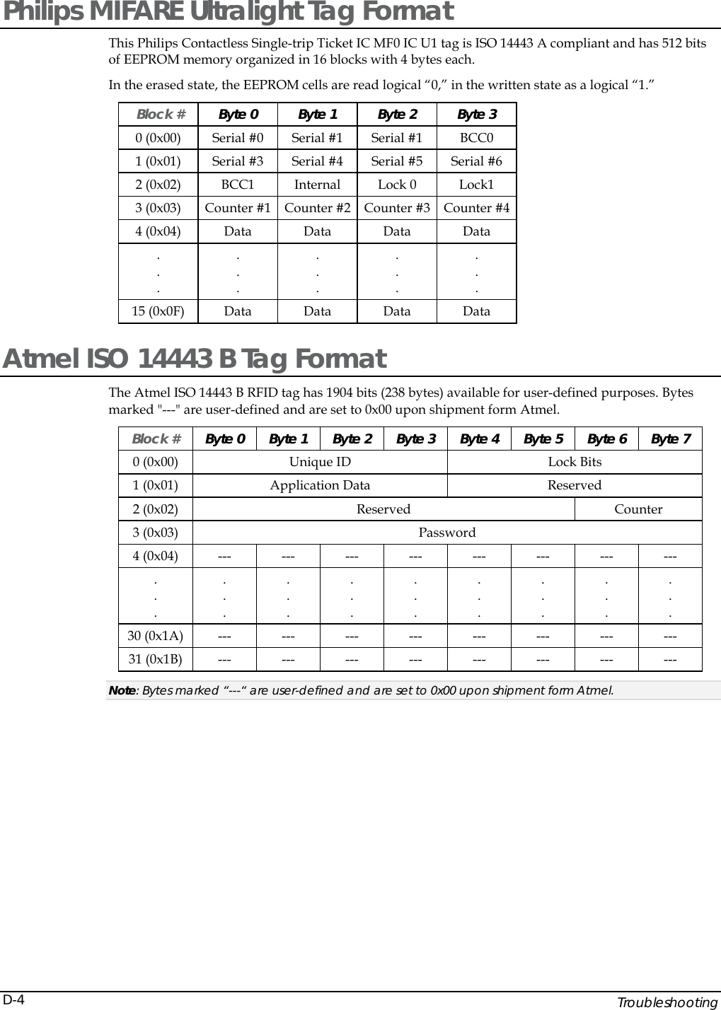
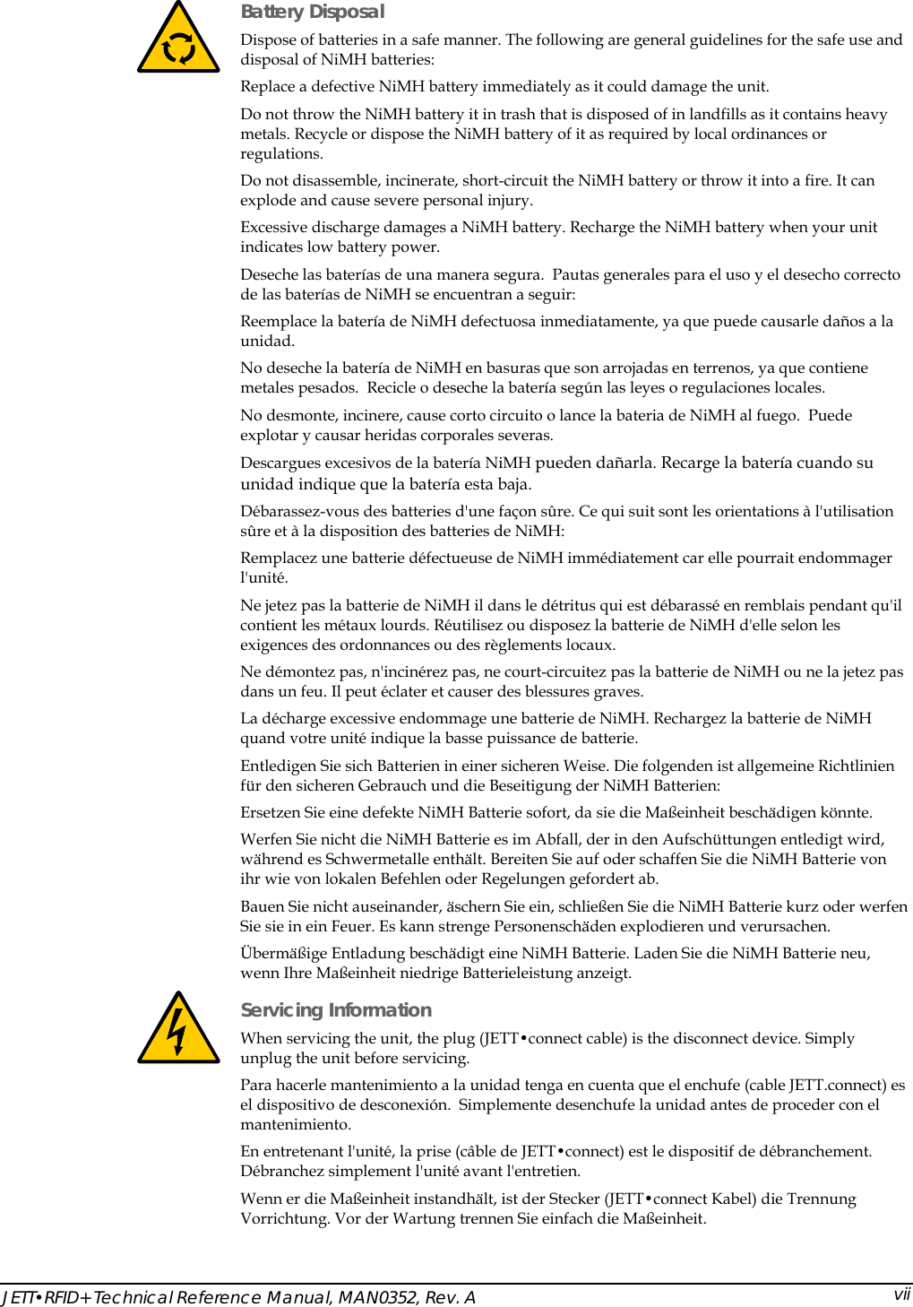
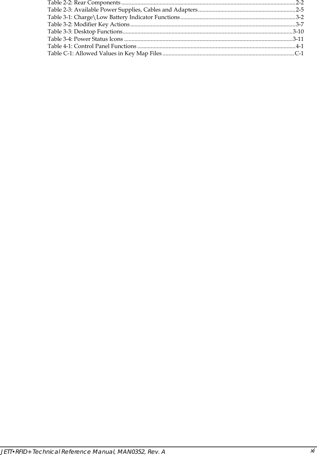
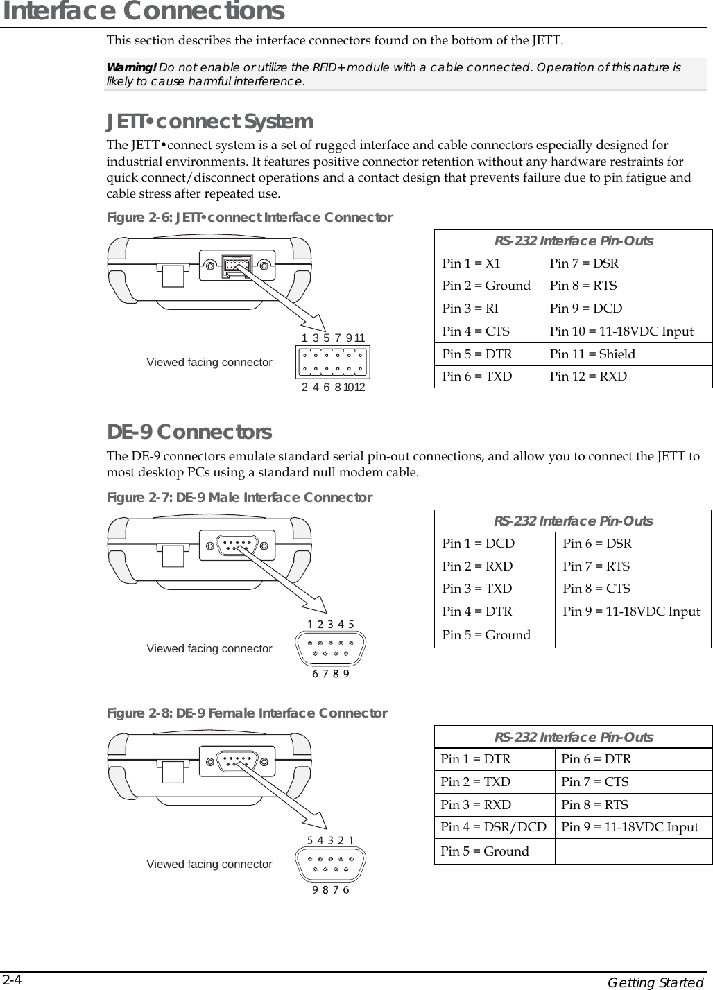
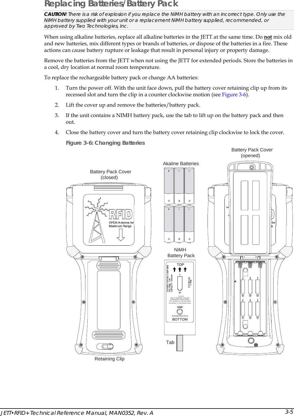
![Application Development 5-18LedUpdate This function enables you to turn on and turn off the LEDs on the JETT. Syntax bool LedUpdate( LEDVALUE ledVal, bool bValue ); Parameters Values Description ledVal [In] Specifies of the following LEDs: LED_2ND LED_SHIFT LED_CTRL LED_ALT LED_CAPS bValue [In] TRUE turns on specified LED. FALSE turns off specified LED. Return Values Values Description TRUE Indicates success. FALSE Indicates failure. GetMacAddress This function returns the MAC address of the JETT, where the high order of the MAC address (pHighMac) returns a two-character value (always 48) and the low order of the MAC address (pLowMac) a unique ten-character value. For example: High Value: 48 Low Value: 3472888915 You can use the pLowMac value to uniquely identify each JETT. This number can be helpful in an environment (such as Bluetooth) where multiple units can report to a single host device. Syntax bool GetMacAddress( PDWORD pHighMac, PDWORD pLowMac ); Parameters Values Description pHighMac [Out] Specifies a two-character value (always 48). pLowMac [Out] Specifies a unique ten-character value. Return Values Values Description TRUE Indicates success. FALSE Indicates failure.](https://usermanual.wiki/Two-Technologies/JETTRFIDPLUS/User-Guide-603360-Page-66.png)
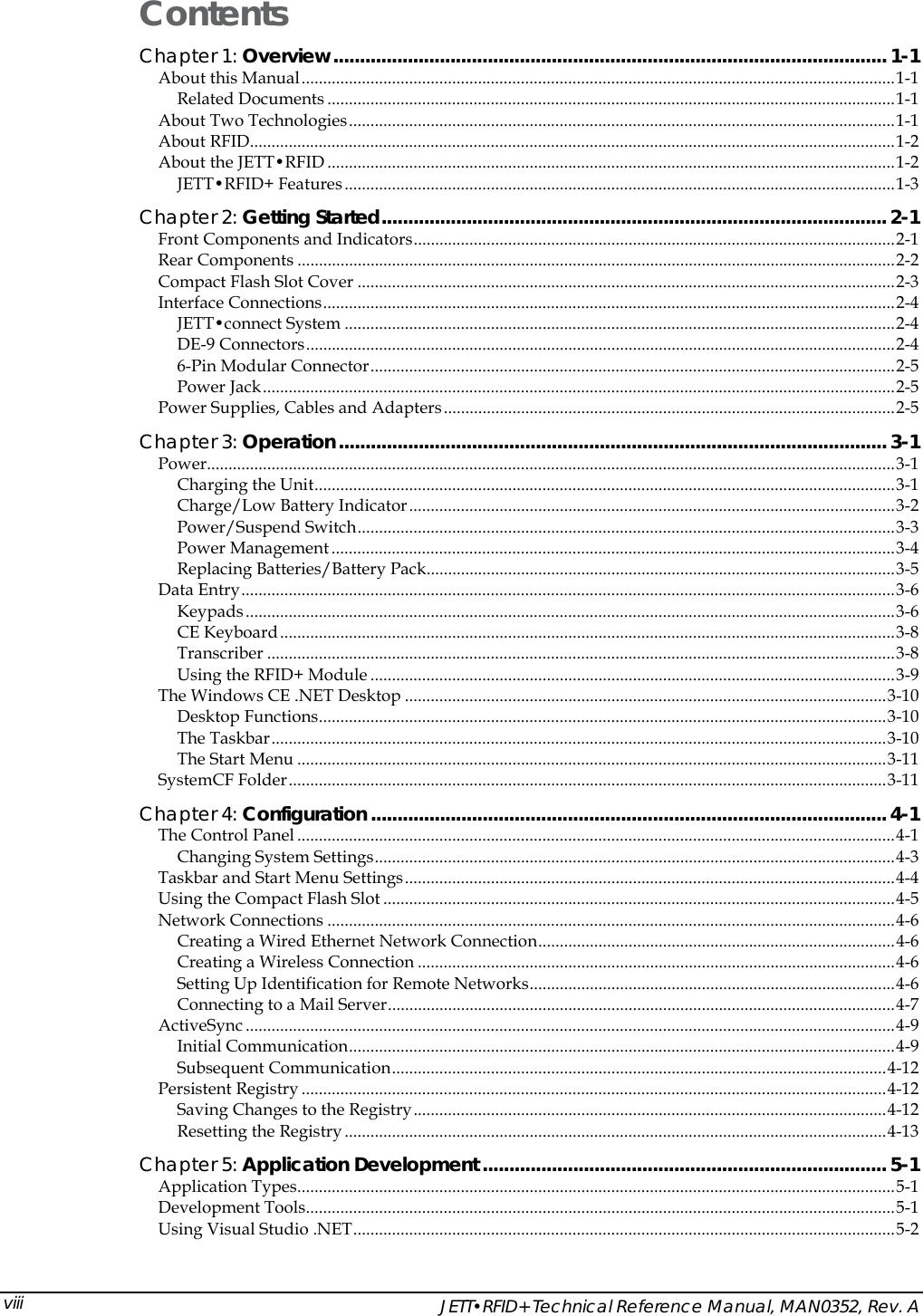
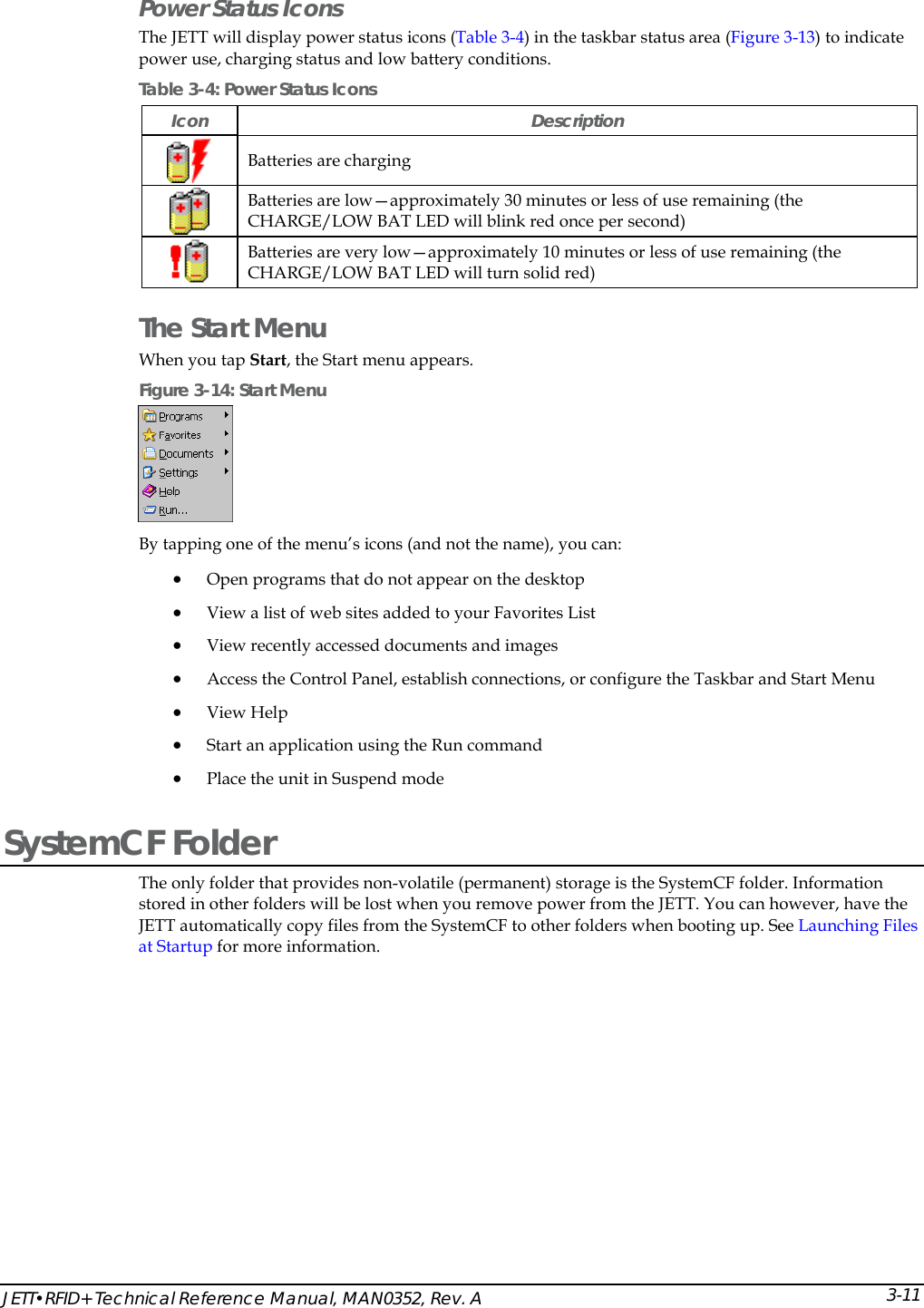
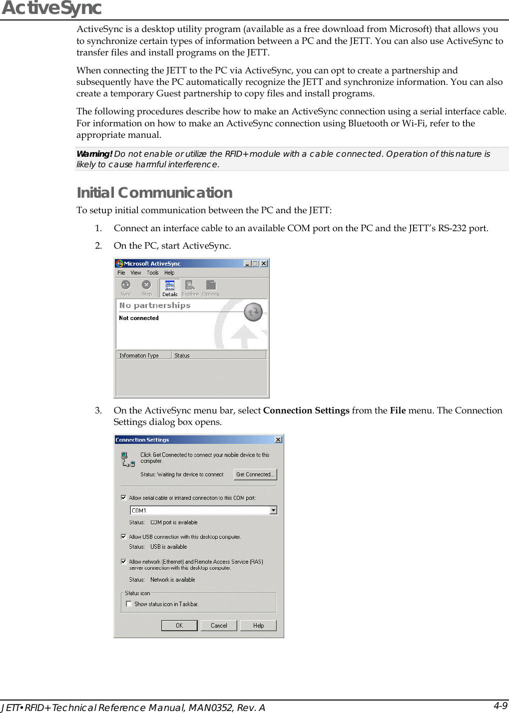
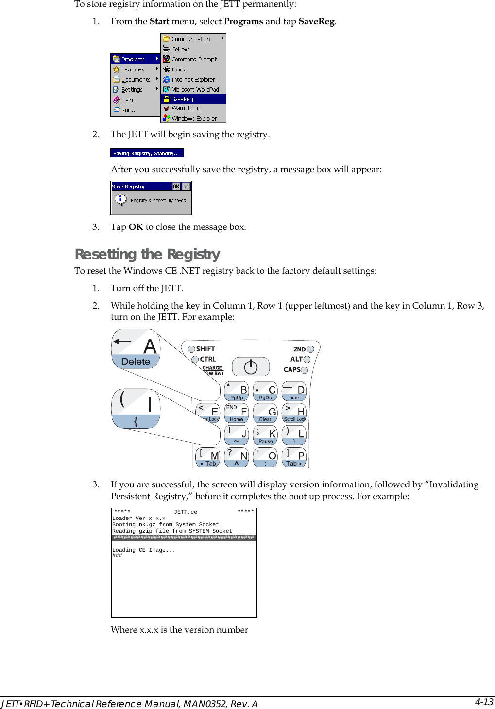
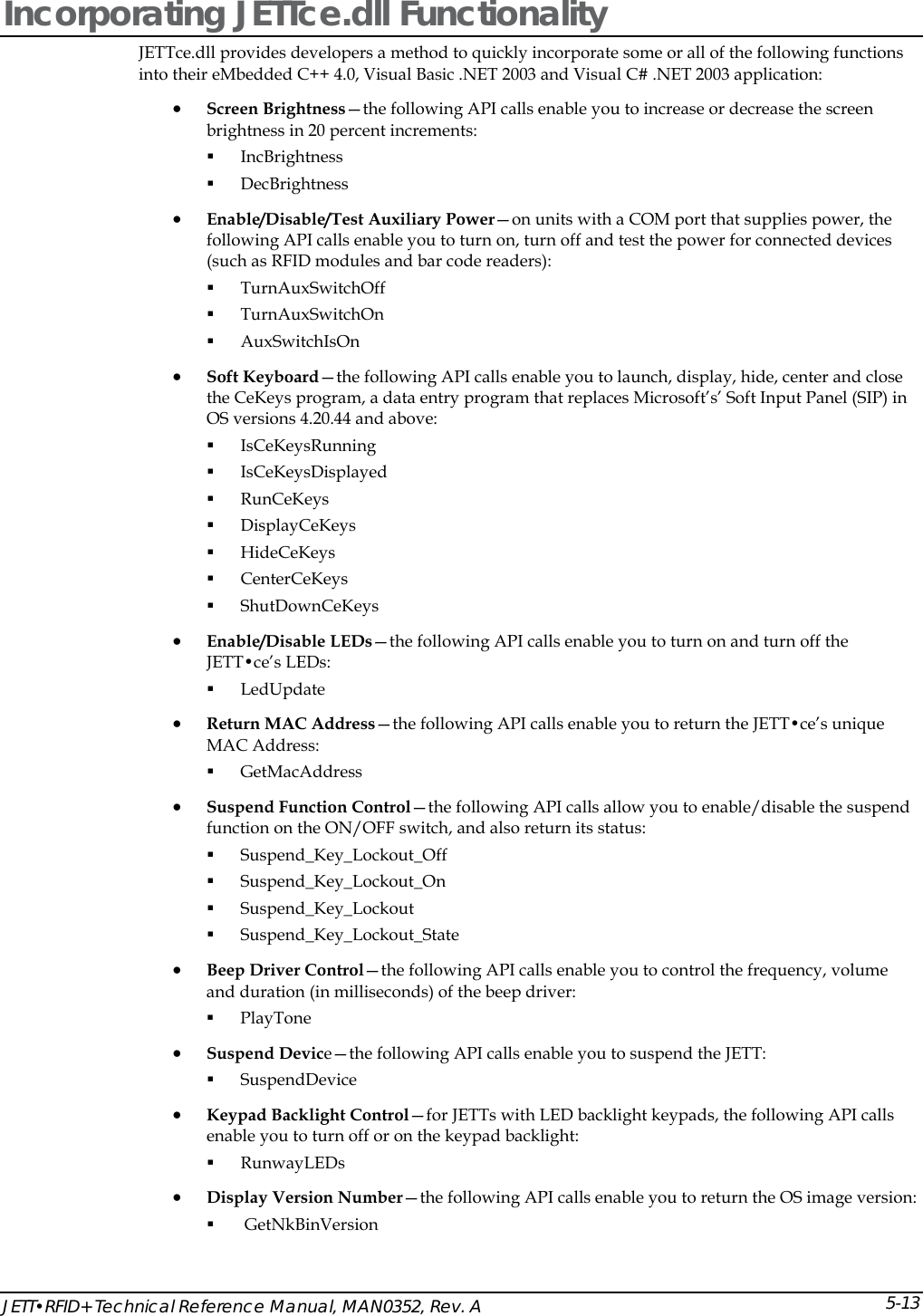
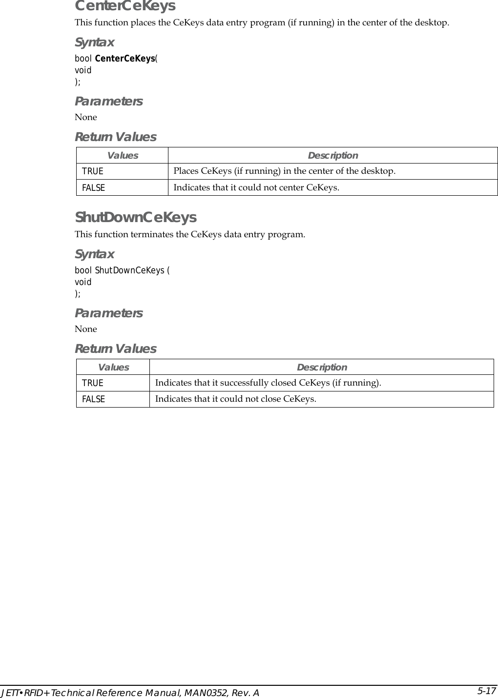
![JETT•RFID+ Technical Reference Manual, MAN0352, Rev. A 5-19Suspend_Key_Lockout_Off This function enables the suspend/resume function. Syntax bool Suspend_Key_Lockout_Off( void ); Parameters None Return Values Values Description TRUE Indicates that you can suspend the unit. FALSE Indicates that the function failed. Suspend_Key_Lockout_On This function disables the suspend/resume function. Syntax bool Suspend_Key_Lockout_On( void ); Parameters None Return Values Values Description TRUE Indicates that you cannot suspend the unit. FALSE Indicates that the function failed. Suspend_Key_Lockout_State This function returns the status of the current suspend/resume lockout state Syntax bool Suspend_Key_Lockout_State( PDWORD pdwLockoutState ); Parameters Values Description pdwLockoutState [Out] Returns the status of the suspend lockout state, where 1 = TRUE and 0 = FALSE. Return Values Values Description TRUE Indicates success. FALSE Indicates failure.](https://usermanual.wiki/Two-Technologies/JETTRFIDPLUS/User-Guide-603360-Page-67.png)
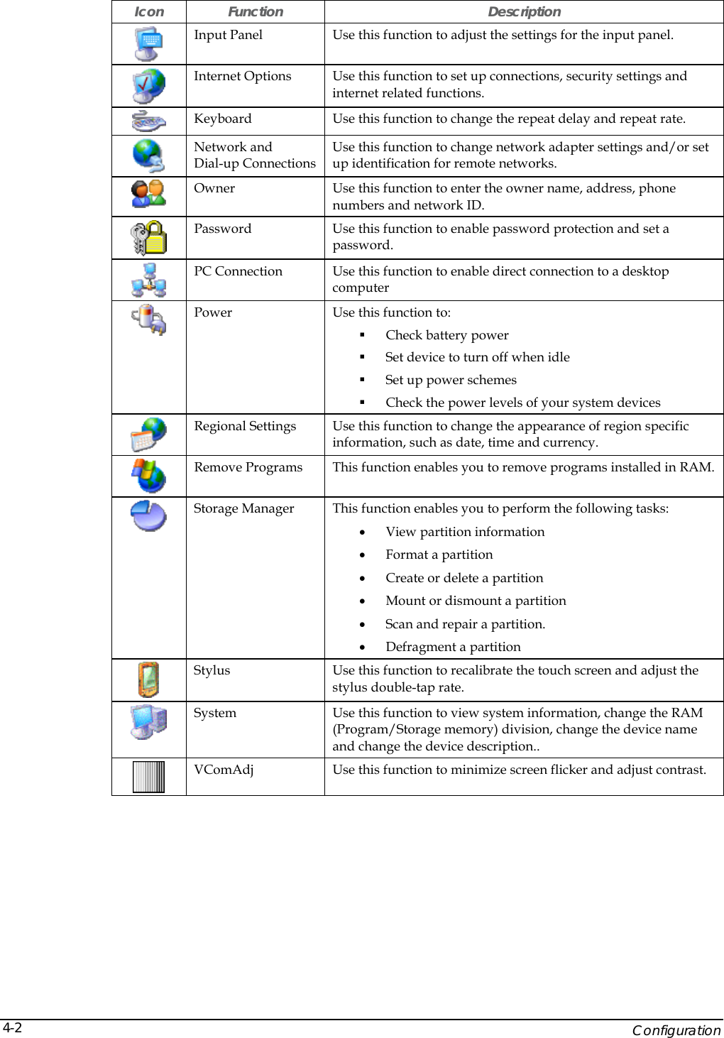
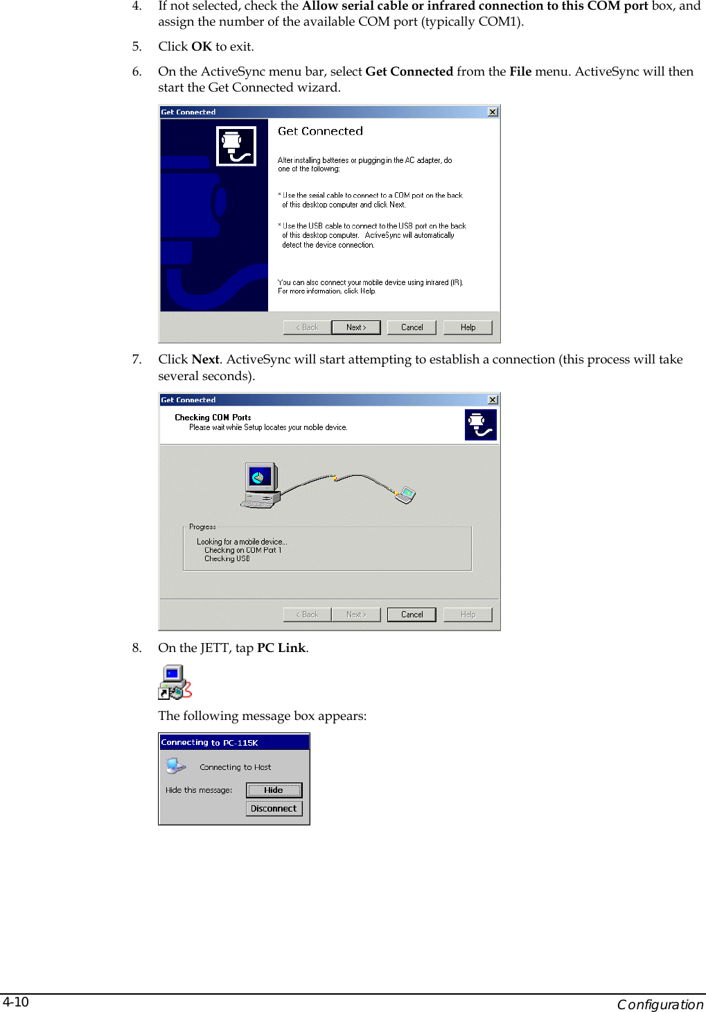
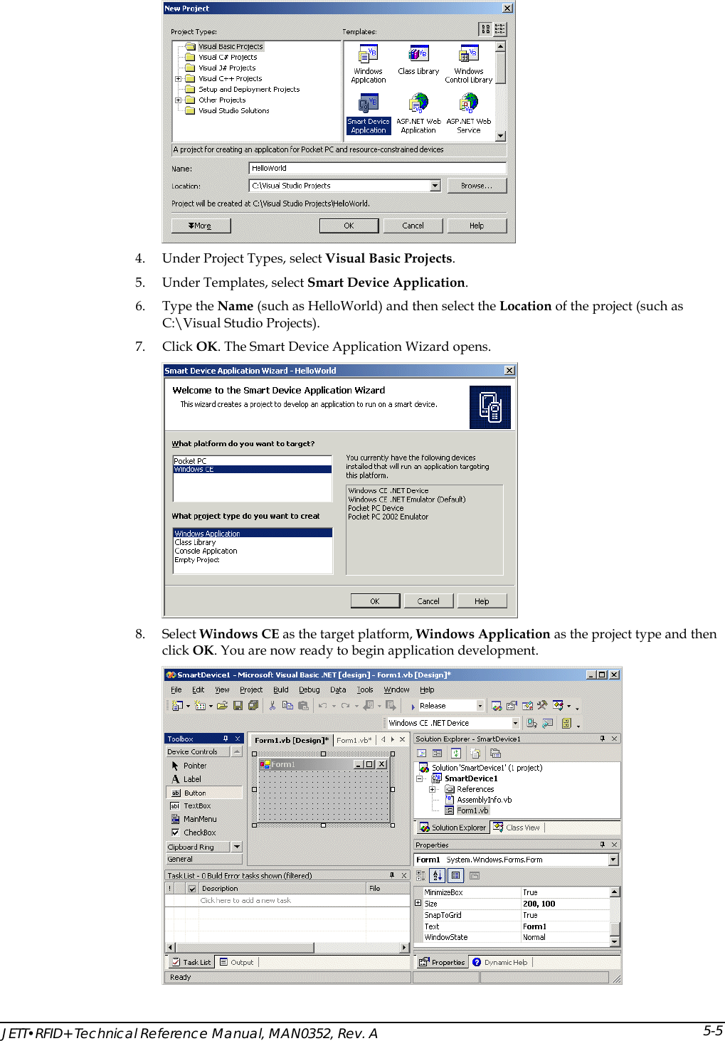
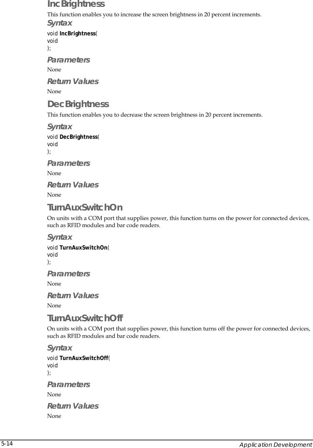
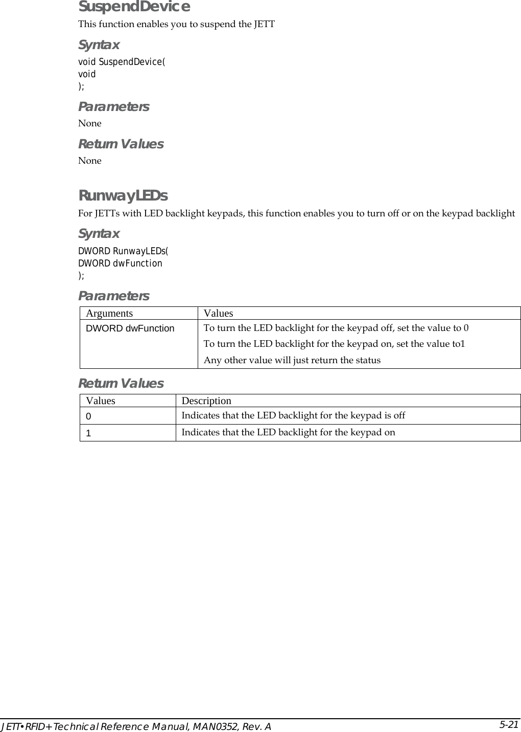
![Application Development 5-20Suspend_Key_Lockout This function allows you enable, disable and return the status of the suspend/resume function on the On/Off switch Syntax bool Suspend_Key_Lockout( PBOOL pbLockoutState ); Parameters Values Description pbLockoutState Specifies one of the following: [In] LOCKOUT_OFF [In] LOCKOUT_ON [Out] LOCKOUT_READ Return Values Values Description TRUE Indicates success. FALSE Indicates failure. PlayTone This function enables you to access the beep driver for various purposes, such as notifying an operator that a malfunction occurred or that a process has finished. Parameters that you can define include frequency, volume and duration (in milliseconds). Syntax bool PlayTone( int iFrequency, int iVolume, int iDurationMS ); Parameters Values Description iFrequency Specifies the beep frequency. Range: 56 to 20000 KHz. iVolume Specifies the beep volume. Range: 1 to 100. iDurationMS Specifies the beep duration in milliseconds Range 1 to 10000 (10 seconds). Return Values Values Description TRUE Indicates success. FALSE Indicates failure.](https://usermanual.wiki/Two-Technologies/JETTRFIDPLUS/User-Guide-603360-Page-68.png)
![Application Development 5-24InitRFID This function enables the RFID+ module. When you call this function, it opens the COM2 port on the JETT•RFID+ at 57600 kbs and turns on the auxiliary power Syntax bool InitRFID( int iErrorCode ); Parameters Values Description iErrorCode [Out] Pointer to the error code if this function fails. Return Values Values Description TRUE Indicates success. FALSE Indicates otherwise (error code returned though pointer). GetFirmwareVersion This function reads the firmware version from the RFID+ module. You can call this function anytime after you initialize the RFID+ module with the InitRFID function. Syntax bool GetFirmwareVersion ( BSTR bsVersion, int iBytes int iErrorCode ); Parameters Values Description bsVersion [Out] Buffer that contains data read from the RFID+ module. iBytes [In] Number of data bytes in the bsVersion buffer. iErrorCode [Out] Pointer to the error code if this function fails. Return Values Values Description TRUE Indicates success. FALSE Indicates otherwise (error code returned though pointer).](https://usermanual.wiki/Two-Technologies/JETTRFIDPLUS/User-Guide-603360-Page-72.png)
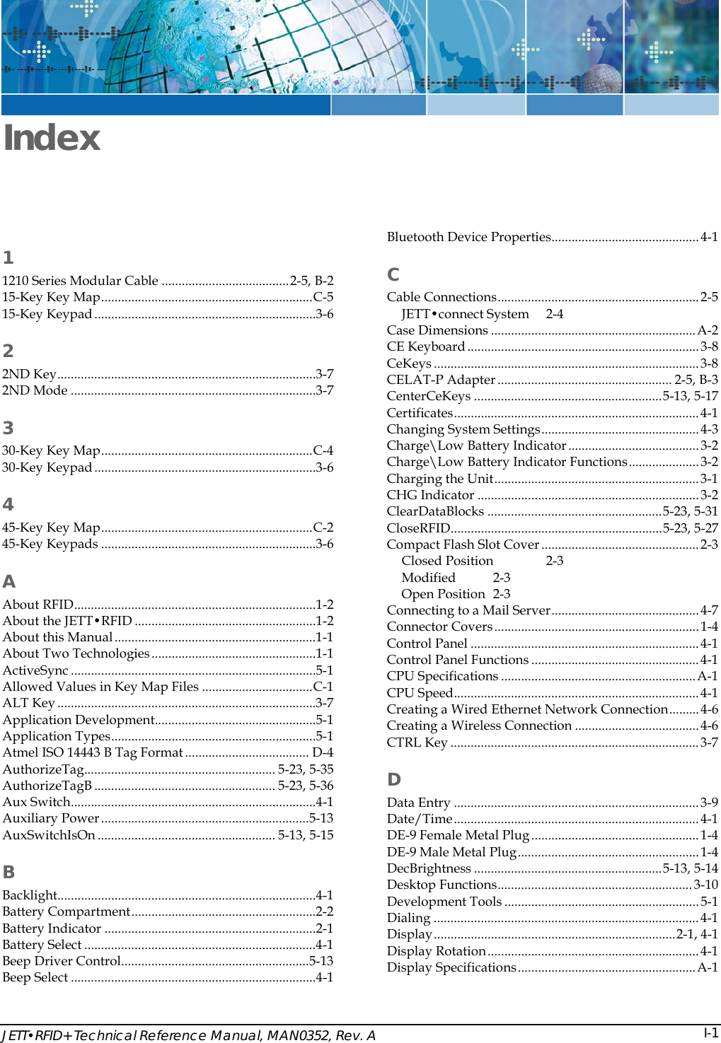
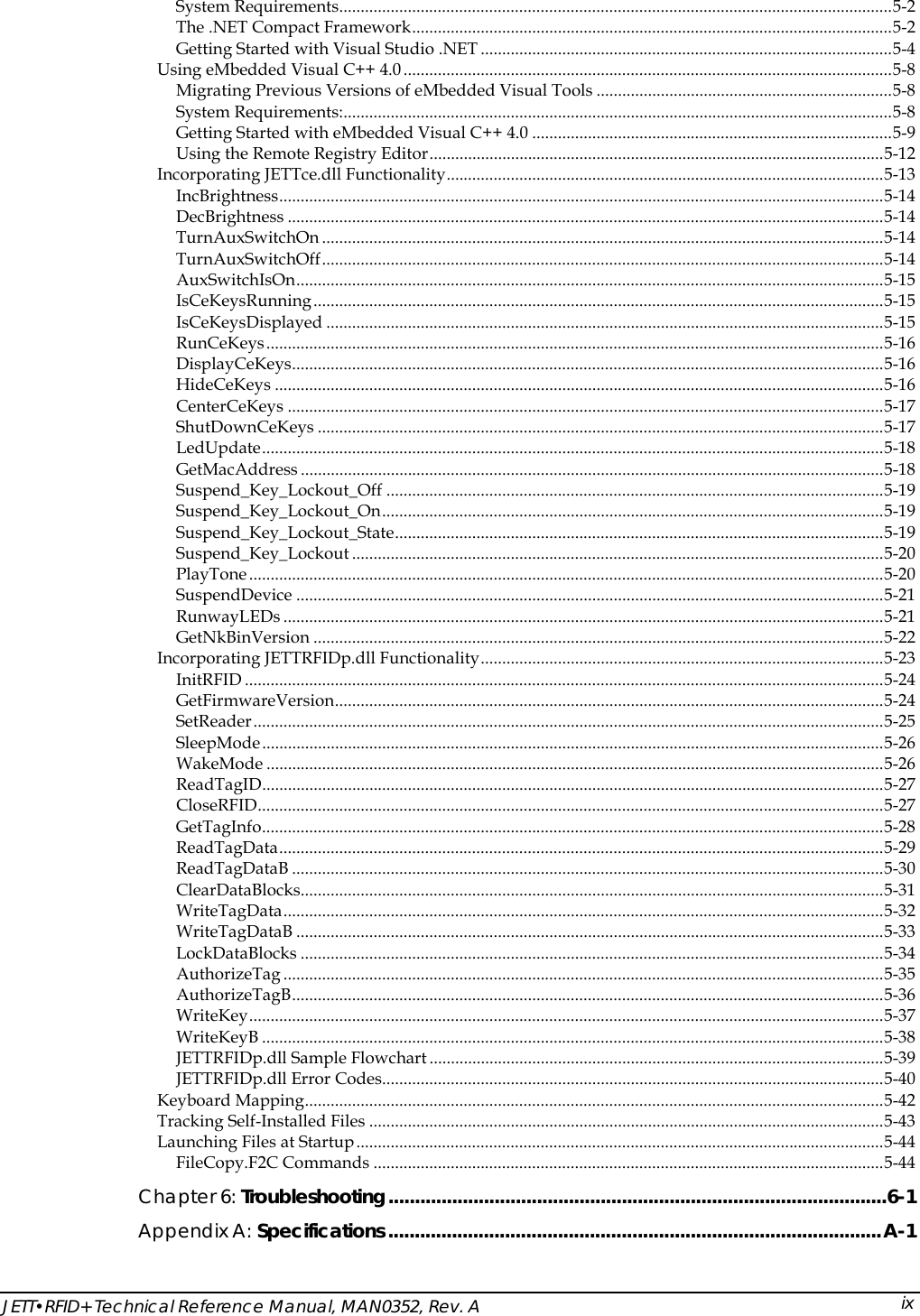
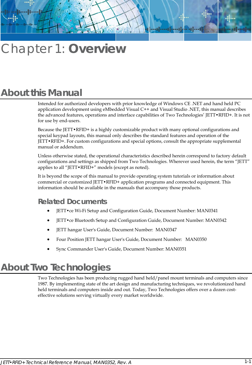
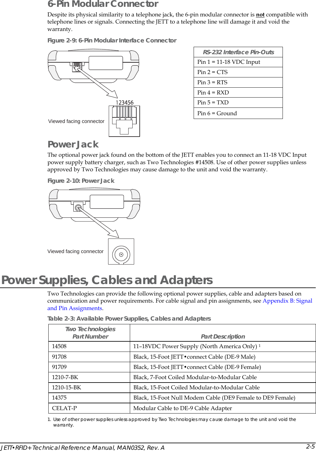
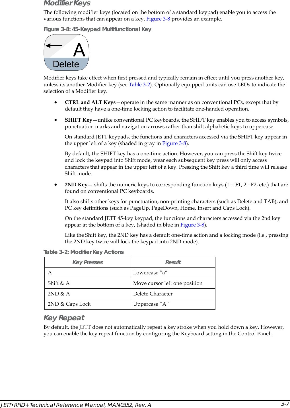
![JETT•RFID+ Technical Reference Manual, MAN0352, Rev. A 5-25SetReader This function sets up the RFID+ module to read tag IDs (use the ReadTagID function to read the tags). Note: When using loop mode, you can continuously call the ReadTagID function to find tag IDs. In addition, you will only need to call this function once until you send another command to the RFID module. Syntax bool SetReader ( RFID_FLAG rfFlag, RFID_TAGTYPE rtTagType, int iErrorCode ); Parameters Values Description rfFlag [In] Flag sent to the reader to indicate one of the following read modes: FLAG_00_SELECT_TAG—the RFID+ module will just read the first tag encountered within its range. FLAG_01_SELECT_TAG_LOOP—the RFID+ module will continuously read tags within its range (even the same tag several times) until you send it another command. FLAG_02_ANTI_COLLISION—the RFID+ module will read all ISO15693 tags encountered within its range once, storing each tag ID FLAG_03_ANTI_COLLISION_LOOP— the RFID+ module will read all ISO15693 tags encountered within its range once, storing each tag ID but continue to scan for additional tags until you send it another command. rtTagType [In] Specifies one of the following tag types: TAGTYPE_00_AUTO_DETECT TAGTYPE_01_ISO15693 TAGTYPE_04_ISO14443A TAGTYPE_05_ISO14443B iErrorCode [Out] Pointer to the error code if this function fails. Return Values Values Description TRUE Indicates success. FALSE Indicates otherwise (error code returned though pointer).](https://usermanual.wiki/Two-Technologies/JETTRFIDPLUS/User-Guide-603360-Page-73.png)
![Application Development 5-26SleepMode This function puts the RFID+ module into sleep mode to conserve power. You can call this function anytime after calling the InitRFID function. Any command sent to the RFID+ module will automatically wake the module. You can also use the WakeMode function. Syntax bool SleepMode( int iErrorCode, ); Parameters Values Description iErrorCode [Out] Pointer to the error code if this function fails. Return Values Values Description TRUE Indicates success. FALSE Indicates otherwise (error code returned though pointer). WakeMode This function wakes the RFID+ module from sleep mode. You can call this function anytime after calling the InitRFID function. See also SleepMode. Syntax bool WakeMode( int iErrorCode, ); Parameters Values Description iErrorCode [Out] Pointer to the error code if this function fails. Return Values Values Description TRUE Indicates success. FALSE Indicates otherwise (error code returned though pointer).](https://usermanual.wiki/Two-Technologies/JETTRFIDPLUS/User-Guide-603360-Page-74.png)
![JETT•RFID+ Technical Reference Manual, MAN0352, Rev. A 5-27 ReadTagID This function reads the unique tag ID from a RFID tag that enters the module’s RF field. Note: You must call the SetReader function prior to calling this function. Syntax bool ReadTagID ( BSTR bsTagID, int iBytes RFID_TAGTYPE rtTagType, int iErrorCode ); Parameters Values Description bsTagID [Out] Buffer that will receive the data read from the tag. iBytes [In] Number of data bytes in the bsTagID buffer. rtTagType [Out] Returns the tag type when using AUTO_DETECT in the SetReader function. Otherwise, the parameter returns zero. iErrorCode [Out] Pointer to the error code if this function fails. Return Values Values Description TRUE Indicates success. FALSE Indicates otherwise (error code returned though pointer). CloseRFID This function closes the RFID module. When you call this function, it turns off the COM2 port on the JETT•RFID+ and auxiliary power to the RFID module. Syntax bool CloseRFID( int iErrorCode, ); Parameters Values Description iErrorCode [Out] Pointer to the error code if this function fails. Return Values Values Description TRUE Indicates success. FALSE Indicates otherwise (error code returned though pointer).](https://usermanual.wiki/Two-Technologies/JETTRFIDPLUS/User-Guide-603360-Page-75.png)
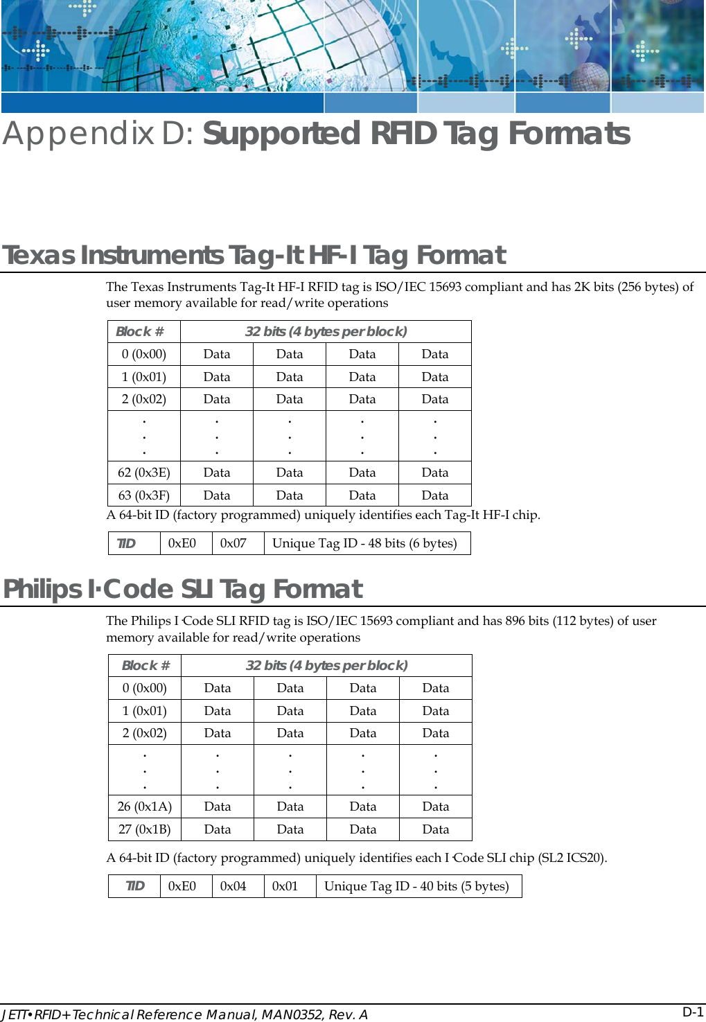
![Application Development 5-28GetTagInfo This function returns the tag information for the entered tag. When you call this function, the RFID+ module confirms the entered tag ID and retrieves the tag’s information as stored in the RFID_TAGINFO structure. Parameters bool GetLastBaudRate ( BSTR bsTagID, RFID_TAGTYPE rtTagType, RFID_TAGINFO rtTagInfo, int iErrorCode ); Parameters Values Description bsTagID [In] Unique tag ID. You can retrieve the Tag ID by calling the SetReader and the ReadTagID functions. rtTagType [In] Specifies one of the following tag types: TAGTYPE_01_ISO15693 TAGTYPE_04_ISO14443A TAGTYPE_05_ISO14443B rtTagInfo [Out] Pointer to the structure that stores the tag information. See RFID_TAGINFO Structure table below. iErrorCode [Out] Pointer to the error code if this function fails. RFID_TAGINFO Structure Value Description int iBytesPerBlock int iNumBlocks int iNumSectors int iStartBlock Return Values Values Description TRUE Indicates success. FALSE Indicates otherwise (error code returned though pointer).](https://usermanual.wiki/Two-Technologies/JETTRFIDPLUS/User-Guide-603360-Page-76.png)
![JETT•RFID+ Technical Reference Manual, MAN0352, Rev. A 5-29ReadTagData This function reads data from the data blocks of a specific RFID tag and copies the data into the bsTagData buffer. It will return all characters from the tag's data area until it encounters the first null character. You can only read 64 bytes of data on any one call to this function. You can only read 64 bytes of data on any one call to this function. Note: If your application requires encrypting and decrypting data, you should do it before writing the data and after reading the data. Syntax bool ReadTagData ( BSTR bsTagID, RFID_TAGTYPE rtTagType, int iStartBlock, int iNumBlocks, BSTR bsTagData, int iBytes int iErrorCode ); Parameters Values Description bsTagID [In] Unique tag ID. You can retrieve the Tag ID by calling the SetReader and the ReadTagID functions. rtTagType [In] Specifies one of the following tag types: TAGTYPE_01_ISO15693 TAGTYPE_04_ISO14443A TAGTYPE_05_ISO14443B iStartBlock [In] Starting block number (dependant on tag type). iNumBlocks [In] Number of data blocks to read (up to 64 bytes). bsTagData [Out] Pointer to the buffer that contains the data read from the tag. iBytes [In] Number of data bytes in the bsTagData buffer. iErrorCode [Out] Pointer to the error code if this function fails. Return Values Values Description TRUE Indicates success. FALSE Indicates otherwise (error code returned though pointer).](https://usermanual.wiki/Two-Technologies/JETTRFIDPLUS/User-Guide-603360-Page-77.png)
![Application Development 5-30ReadTagDataB This function reads data from the data blocks of a specific RFID tag and copies the data into the bTagData buffer. It will return all characters from the tag's data area including null characters. You can only read 64 bytes of data on any one call to this function. Note: If your application requires encrypting and decrypting data, you should do it before writing the data and after reading the data. Syntax bool ReadTagDataB ( BSTR bsTagID, RFID_TAGTYPE rtTagType, int iStartBlock, int iNumBlocks, BYTE bTagData, int iBytes int iErrorCode ); Parameters Values Description bsTagID [In] Unique tag ID. You can retrieve the Tag ID by calling the SetReader and the ReadTagID functions. rtTagType [In] Specifies one of the following tag types: TAGTYPE_01_ISO15693 TAGTYPE_04_ISO14443A TAGTYPE_05_ISO14443B iStartBlock [In] Starting block number (dependant on tag type). iNumBlocks [In] Number of data blocks to read (up to 64 bytes). bTagData [Out] Pointer to the buffer that contains the data read from the tag. iBytes [In] Number of data bytes in the bTagData buffer. iErrorCode [Out] Pointer to the error code if this function fails. Return Values Values Description TRUE Indicates success. FALSE Indicates otherwise (error code returned though pointer).](https://usermanual.wiki/Two-Technologies/JETTRFIDPLUS/User-Guide-603360-Page-78.png)
![JETT•RFID+ Technical Reference Manual, MAN0352, Rev. A 5-31ClearDataBlocks This function clears the data blocks for a specific RFID tag, identified by its tag ID. When you call this function, the RFID+ module writes null characters to the specified data blocks of the tag ID supplied. Starting blocks, the number of data blocks, and the block size (4 or 8 bytes) will vary according to the tag type. You can only clear 64 bytes of data on any one call to this function. Syntax bool ClearDataBlocks ( BSTR bsTagID, RFID_TAGTYPE rtTagType, int iStartBlock, int iNumBlocks, int iErrorCode ); Parameters Values Description bsTagID [In] Unique tag ID. You can retrieve the Tag ID by calling the SetReader and the ReadTagID functions. rtTagType [In] Specifies one of the following tag types: TAGTYPE_01_ISO15693 TAGTYPE_04_ISO14443A TAGTYPE_05_ISO14443B iStartBlock [In] Starting block number (dependant on tag type). iNumBlocks [In] Number of data blocks to clear (up to 64 bytes). iErrorCode [Out] Pointer to the error code if this function fails. Return Values Values Description TRUE Indicates success. FALSE Indicates otherwise (error code returned though pointer).](https://usermanual.wiki/Two-Technologies/JETTRFIDPLUS/User-Guide-603360-Page-79.png)
![Application Development 5-32WriteTagData This function writes the entered data to the tag’s data blocks until it encounters the first null character. It automatically calculates the number of data blocks required and fills partially written blocks with null characters. You can only write 64 bytes of data on any one call to this function. You should use this function when writing null terminated character strings within the 96-character ASCII set (decimal values 20 through 127). Notes: You can only write 64 bytes of data on any one call to this function. If your application requires encrypting and decrypting data, you should do it before writing the data and after reading the data. Syntax bool WriteTagData ( BSTR bsTagID, RFID_TAGTYPE rtTagType, int iStartBlock, BSTR bsTagData, int iErrorCode ); Parameters Values Description bsTagID [In] Unique tag ID. You can retrieve the Tag ID by calling the SetReader and the ReadTagID functions. rtTagType [In] Specifies of the following tag types: TAGTYPE_01_ISO15693 TAGTYPE_04_ISO14443A TAGTYPE_05_ISO14443B iStartBlock [In] Starting block number (dependant on tag type). bsTagData [In] Pointer to the buffer that contains the data written to the tag. iErrorCode [Out] Pointer to the error code if this function fails. Return Values Values Description TRUE Indicates success. FALSE Indicates otherwise (error code returned though pointer).](https://usermanual.wiki/Two-Technologies/JETTRFIDPLUS/User-Guide-603360-Page-80.png)
![JETT•RFID+ Technical Reference Manual, MAN0352, Rev. A 5-33WriteTagDataB This function writes all the entered data to the tag’s data blocks including null characters. It automatically calculates the number of data blocks required and fills partially written blocks with null characters. You can only write 64 bytes of data on any one call to this function. You should use this function when writing any character within the ASCII character set (decimal values 0 through 255). Notes: If your application requires encrypting and decrypting data, you should do it before writing the data and after reading the data. Syntax bool WriteTagDataB ( BSTR bsTagID, RFID_TAGTYPE rtTagType, int iStartBlock, BYTE bTagData, int iNumBytesToWrite int iErrorCode ); Parameters Values Description bsTagID [In] Unique tag ID. You can retrieve the Tag ID by calling the SetReader and the ReadTagDataB functions. rtTagType [In] Specifies of the following tag types: TAGTYPE_01_ISO15693 TAGTYPE_04_ISO14443A TAGTYPE_05_ISO14443B iStartBlock [In] Starting block number (dependant on tag type). bTagData [In] Pointer to the buffer that contains the data you will write to the tag. iNumBytesToWrite [In] Contains the number of bytes you will write to the bTagData buffer. iErrorCode [Out] Pointer to the error code if this function fails. Return Values Values Description TRUE Indicates success. FALSE Indicates otherwise (error code returned though pointer).](https://usermanual.wiki/Two-Technologies/JETTRFIDPLUS/User-Guide-603360-Page-81.png)
![Application Development 5-34LockDataBlocks This function locks a data block for a specified RFID tag, permanently preserving that data contained in that block. Starting blocks, the number of data blocks, and the block size (4 or 8 bytes) will vary according to the tag type. You can only lock 64 bytes of data on any one call to this function. Note: Once you lock a block, you can never write data or erase the contents of that block again. Syntax bool LockDataBlocks ( BSTR bsTagID, RFID_TAGTYPE rtTagType, int iStartBlock, int iNumBlocks, int iErrorCode ); Parameters Values Description bsTagID [In] Unique tag ID. You can retrieve the Tag ID by calling the SetReader and the ReadTagID functions. rtTagType [In] Specifies one of the following tag types: TAGTYPE_01_ISO15693 TAGTYPE_04_ISO14443A TAGTYPE_05_ISO14443B iStartBlock [In] Starting block number (dependant on tag type). iNumBlocks [In] Number of data blocks to lock (up to 64 bytes). iErrorCode [Out] Pointer to the error code if this function fails. Return Values Values Description TRUE Indicates success. FALSE Indicates otherwise (error code returned though pointer).](https://usermanual.wiki/Two-Technologies/JETTRFIDPLUS/User-Guide-603360-Page-82.png)
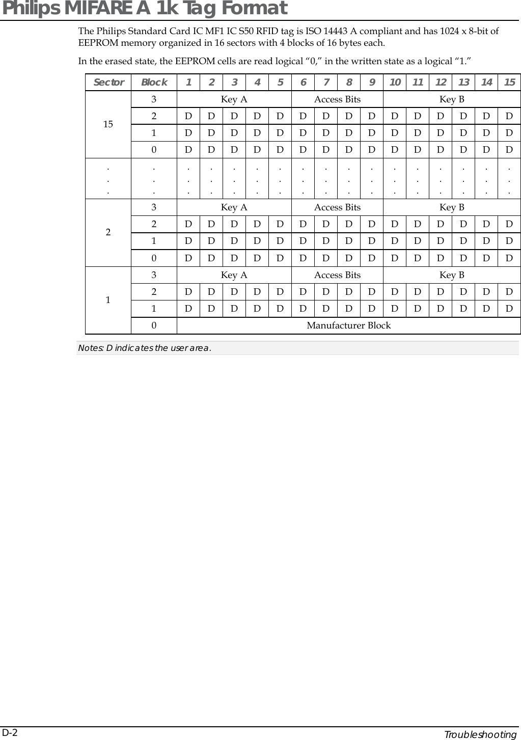
![JETT•RFID+ Technical Reference Manual, MAN0352, Rev. A 5-35AuthorizeTag This function authorizes a ISO/IEC 14443 tag key to read and write data to the tag’s data area. When you call this function, the RFID+ module uses the entered key to authorize the tag for reading and writing data. You should use this function when authorizing keys that are NULL terminated character strings within the 96-ASCII character set. All ISO/IEC 14443 tags are initially set with a NULL as the default key value. ISO/IEC 14443 A Tags ISO/IEC 14443 A tags support use of two keys (A and B) per sector. When using key A, you can use any value including the default value to authorize tags. When using key B, you must first change the default value before you can authorize tags. Note: MIFARE Ultralight tags use the default parameters values for authorization and do not require keys that contain strings. ISO/IEC 14443 B Tags ISO/IEC 14443 B tags only require the use of one key (A) for authorization.. Syntax bool AuthorizeTag ( BSTR bsTagID, RFID_TAGTYPE rtTagType, int iSectorNumber, BSTR bsKey, RFID_KEYTYPE rtKeyType, int iErrorCode ); Parameters Values Description bsTagID [In] Unique tag ID. You can retrieve the Tag ID by calling the SetReader and the ReadTagID functions. rtTagType [In] Specifies of the following tag types: TAGTYPE_04_ISO14443A TAGTYPE_05_ISO14443B iSectorNumber [In] Sector number used to authorize for ISO14443 A tags. Ignored for other tag types. bsKey [In] Pointer to the buffer that stores the key used for authorization. Use NULL for default key types. rtKeyType [In] Key type to authorize, where: KEYTYPE_KEYA = Key A KEYTYPE_KEYB = Key B KEYTYPE_DEFAULT =Default Key iErrorCode [Out] Pointer to the error code if this function fails. Return Values Values Description TRUE Indicates success. FALSE Indicates otherwise (error code returned though pointer).](https://usermanual.wiki/Two-Technologies/JETTRFIDPLUS/User-Guide-603360-Page-83.png)
![Application Development 5-36AuthorizeTagB This function authorizes an ISO/IEC 14443 tag key to read and write data to the tag’s data area. When you call this function, the RFID+ module uses the entered key to authorize the tag for reading and writing data. You should use this function when authorizing keys that use all data within the ASCII character set excluding NULL characters. However, you must use a NULL character to terminate the string. All ISO/IEC 14443tags are initially set with a NULL as the default key value. ISO/IEC 14443 A Tags ISO/IEC 14443 A tags support use of two keys (A and B) per sector. When using key A, you can use any value including the default value to authorize tags. When using key B, you must first change the default value before you can authorize tags. Note: MIFARE Ultralight tags use the default parameters values for authorization and do not require keys that contain strings. ISO/IEC 14443 B Tags ISO/IEC 14443 tags only require the use of one key (A) for authorization. Syntax bool AuthorizeTagB ( BSTR bsTagID, RFID_TAGTYPE rtTagType, int iSectorNumber, BYTE bKey, RFID_KEYTYPE rtKeyType, int iErrorCode ); Parameters Values Description bsTagID [In] Unique tag ID. You can retrieve the Tag ID by calling the SetReader and the ReadTagID functions. rtTagType [In] Specifies of the following tag types: TAGTYPE_04_ISO14443A TAGTYPE_05_ISO14443B iSectorNumber [In] Sector number used to authorize for ISO14443 A tags. Ignored for other tag types. bKey [In] Pointer to the buffer that stores the key used for authorization. Use NULL for default key types. rtKeyType [In] Key type to authorize, where: KEYTYPE_KEYA =Key A. KEYTYPE_KEYB = Key B. KEYTYPE_DEFAULT =Default Key. iErrorCode [Out] Pointer to the error code if this function fails. Return Values Values Description TRUE Indicates success. FALSE Indicates otherwise (error code returned though pointer).](https://usermanual.wiki/Two-Technologies/JETTRFIDPLUS/User-Guide-603360-Page-84.png)
![JETT•RFID+ Technical Reference Manual, MAN0352, Rev. A 5-37 WriteKey This function writes new keys that contain NULL terminated character strings within the 96-ASCII character set to ISO/IEC 14443 tags authorized via the AuthorizeTag or AuthorizedTagB function. Note: You cannot read tag keys. As a precaution, you should store all key values and related sector numbers. ISO/IEC 14443 A Tags When writing keys for ISO/IEC 14443 A tags, you must use both A and B keys. Both keys by default are set to NULL. If you choose to overwrite the default value, the new key must be six characters in length. In addition, if you change the default value for the B key, you must authorize the B key in order to write new keys to that sector. New keys cannot contain a NULL character as part of the string. ISO/IEC 14443 B Tags When writing keys for ISO/IEC 14443 B tags, you must use both A and B keys. Both keys by default are set to NULL. If you choose to overwrite the default value for the A key (the value of the B key must remain NULL), the new A key must be eight characters in length. In addition, the new key cannot consist of a string of ones (i.e., 11111111) or contain a NULL character as part of the string.. Syntax bool WriteKey ( BSTR bsTagID, RFID_TAGTYPE rtTagType, BSTR bsKeyA, BSTR bsKeyB, int iErrorCode ); Parameters Values Description bsTagID [In] Unique tag ID. You can retrieve the Tag ID by calling the SetReader and the ReadTagID functions. rtTagType [In] Specifies of the following tag types: TAGTYPE_04_ISO14443A TAGTYPE_05_ISO14443B bsKeyA [In] Pointer to the buffer that stores the A key written to the tag. Use NULL for default key types. bsKeyB [In] Pointer to the buffer that stores the B key written to the tag. Use NULL for default key types. iErrorCode [Out] Pointer to the error code if this function fails. Return Values Values Description TRUE Indicates success. FALSE Indicates otherwise (error code returned though pointer).](https://usermanual.wiki/Two-Technologies/JETTRFIDPLUS/User-Guide-603360-Page-85.png)
![Application Development 5-38WriteKeyB This function writes new keys that contain any data within the ASCII character set to ISO/IEC 14443 tags authorized via the AuthorizeTag or AuthorizedTagB function. The string that makes up the key may not contain a NULL character, but you must use a NULL character to terminate the string. Notes: You cannot read tag keys. As a precaution, you should store all key values and related sector numbers. ISO/IEC 14443 A Tags ISO/IEC 14443 A tags support use of two keys (A and B) per sector. You can use either key to authorize a sector for reading and writing data. Note: MIFARE Ultralight tags use the default parameters values for authorization and do not require keys that contain strings. ISO/IEC 14443 B Tags ISO/IEC 14443 tags only require the use of one key (A) for authorization. Syntax bool WriteKeyB ( BSTR bsTagID, RFID_TAGTYPE rtTagType, BYTE bKeyA, BYTE bKeyB, int iErrorCode ); Parameters Values Description bsTagID [In] Unique tag ID. You can retrieve the Tag ID by calling the SetReader and the ReadTagID functions. rtTagType [In] Specifies of the following tag types: TAGTYPE_04_ISO14443A TAGTYPE_05_ISO14443B KEYTYPE_DEFAULT =Default Key bKeyA [In] Pointer to the buffer that stores the A key written to the tag. Use NULL for default key types. bKeyB [In] Pointer to the buffer that stores the B key written to the tag. Use NULL for default key types. iErrorCode [Out] Pointer to the error code if this function fails. Return Values Values Description TRUE Indicates success. FALSE Indicates otherwise (error code returned though pointer).](https://usermanual.wiki/Two-Technologies/JETTRFIDPLUS/User-Guide-603360-Page-86.png)

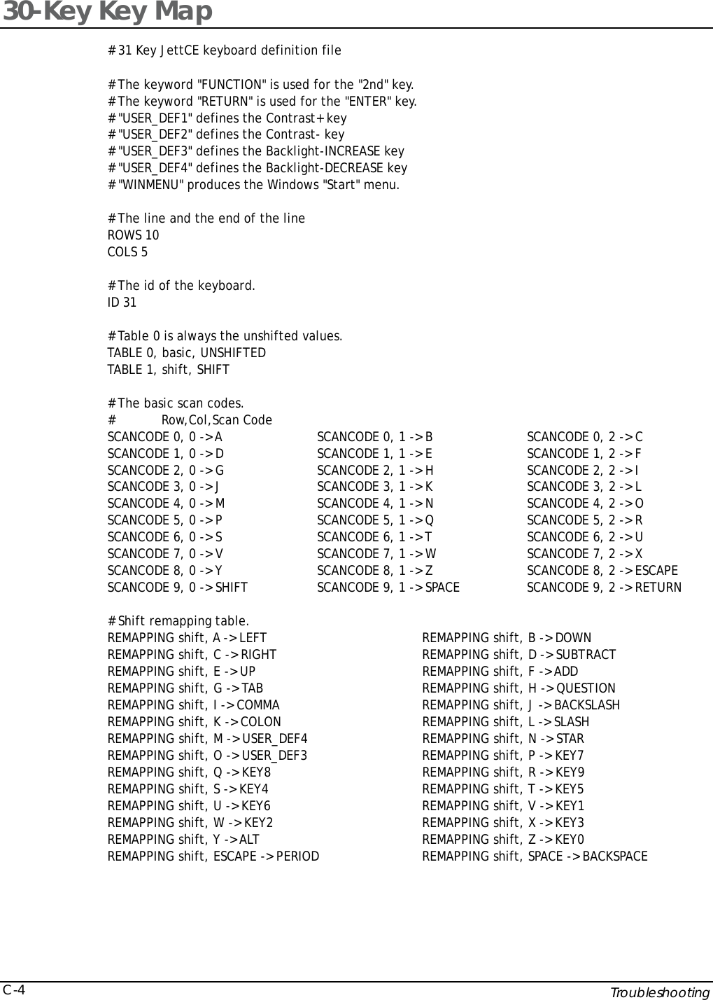
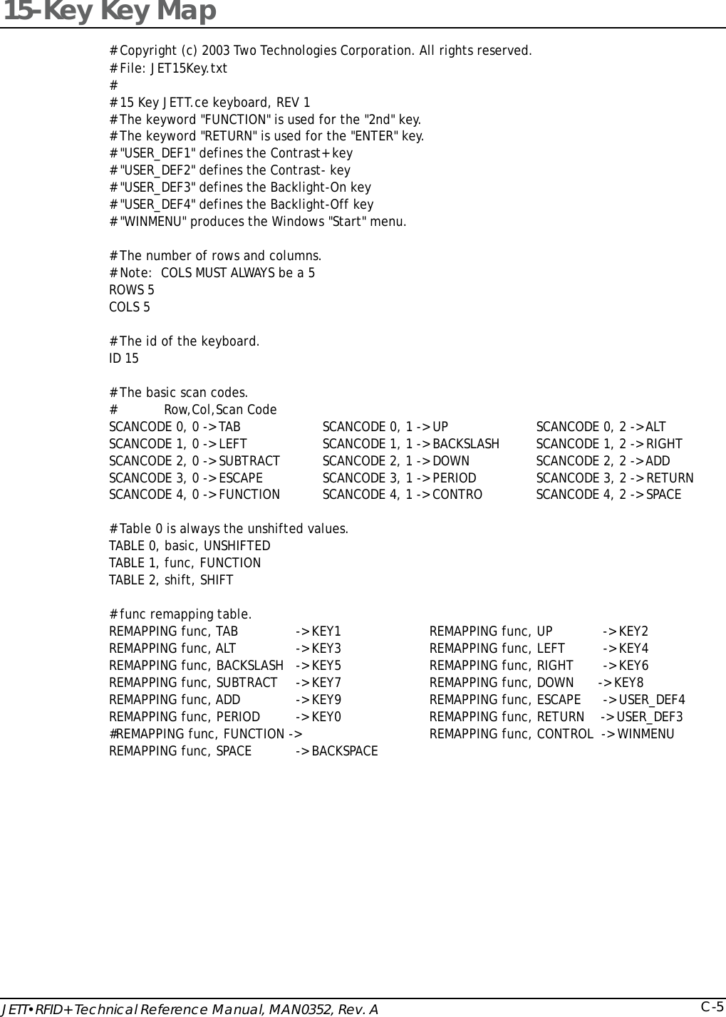
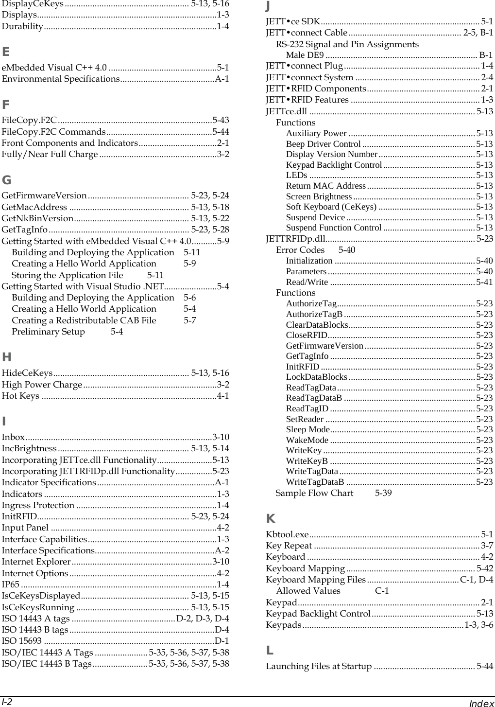
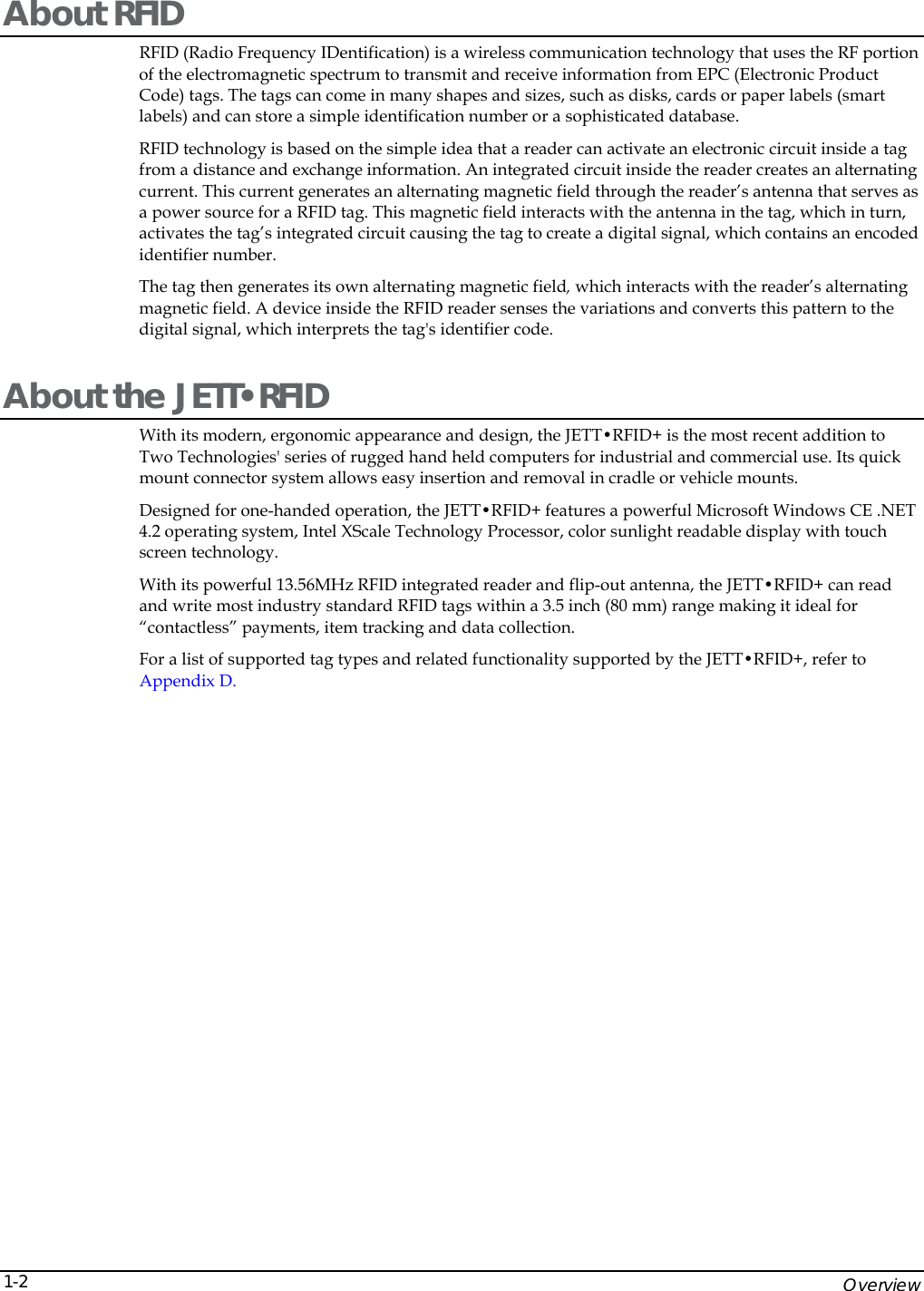
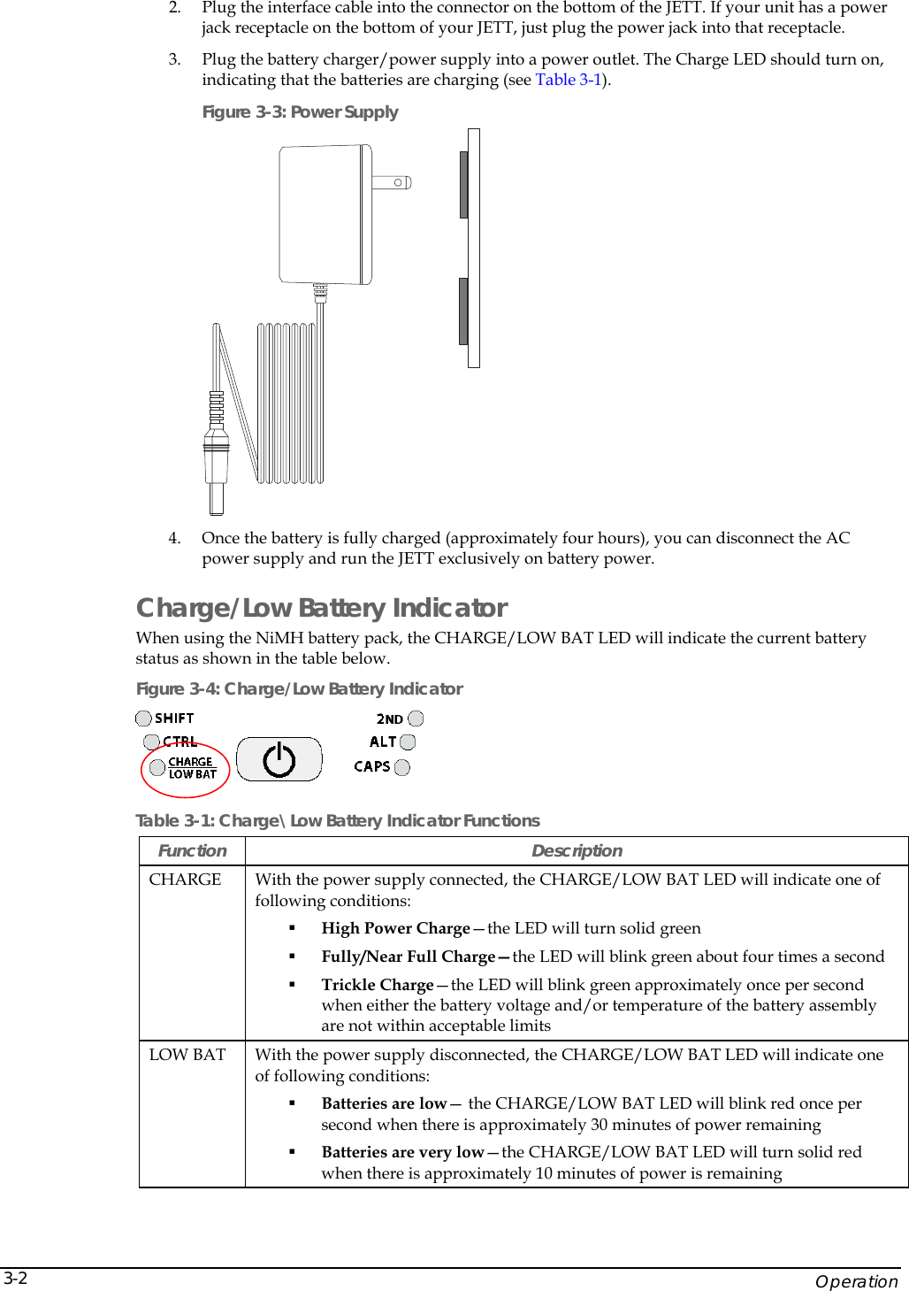
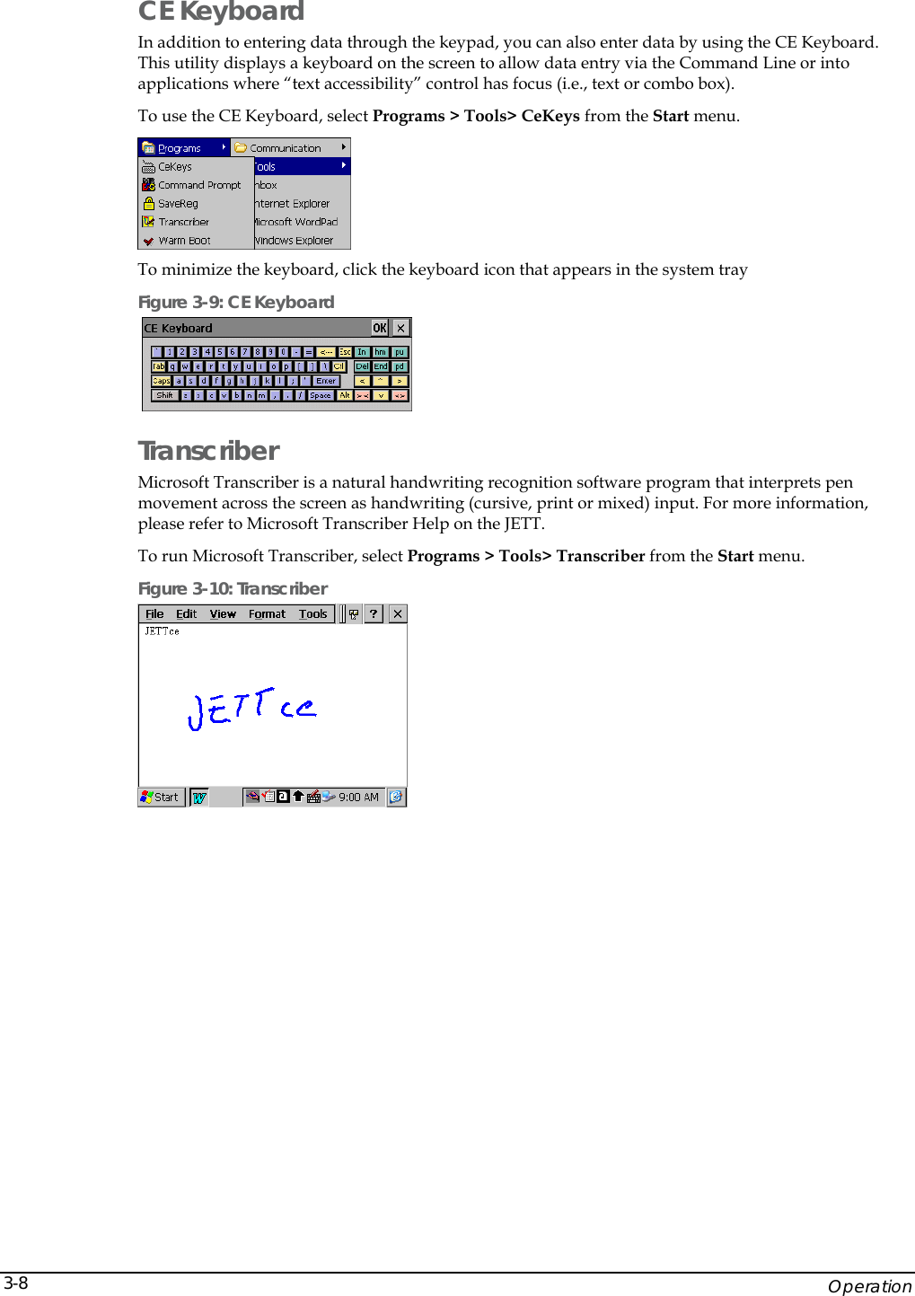
![JETT•RFID+ Technical Reference Manual, MAN0352, Rev. A C-1Appendix C: Keyboard Mapping Files Allowed Values The following table lists the allowable values and the names of allowable values that you can map to a keypad. Table C-1: Allowed Values in Key Map Files A V CARET F9 NUMPAD1 SEMICOLON B W CLEAR F10 NUMPAD2 SHIFT C X COLON F11 NUMPAD3 SLASH D Y COMMA F12 NUMPAD4 SPACE E Z CONTROL FUNCTION NUMPAD5 STAR F ( DELETE HASH NUMPAD6 SUBTRACT G ) DOLLAR HOME NUMPAD7 TAB H [ DOUBLEQUOTE INSERT NUMPAD8 TILDA I ] DOWN LEFT NUMPAD9 UNDERLINE J { END KEY0 PAGEDOWN UP K } EQUAL KEY1 PAGEUP USER_DEF1 L < ESCAPE KEY2 PAUSE USER_DEF2 M > EXCLAMATION KEY3 PERCENT USER_DEF3 N ADD F1 KEY4 PERIOD USER_DEF4 O ALT F2 KEY5 PIPE USER_DEF5 P AMPERSAND F3 KEY6 PRINT USER_DEF6 Q AT F4 KEY7 QUESTION USER_DEF7 R BACKQUOTE F5 KEY8 QUOTE USER_DEF8 S BACKSLASH F6 KEY9 RETURN USER_DEF9 T BACKSPACE F7 NUMLOCK RIGHT USER_DEF10 U CAPSLOCK F8 NUMPAD0 SCROLL WINMENU Scan codes “USER_DEF1” through “USER_DEF10” can produce some proprietary action, such as backlight adjustment, display rotation, etc. For each user-defined key-function (except as noted below), you must supply the appropriate code in the keyboard driver to produce the desired effect. "USER_DEF3" defines the Backlight+ key and "USER_DEF4" defines the Backlight– key. The "FUNCTION" keyword identifies those function accessed through the "2nd" key. The “RETURN" keyword identifies the "ENTER" key. The "WINMENU" keyword produces the Windows "Start" menu. The number in COLS must always be set to five regardless of the actual number of columns (applies to 15-key keypads as well). Do not change the ID number, it must match the number stored in the JETT’s hardware configuration block.](https://usermanual.wiki/Two-Technologies/JETTRFIDPLUS/User-Guide-603360-Page-101.png)
![JETT•RFID+ Technical Reference Manual, MAN0352, Rev. A C-3REMAPPING func, KEY4 -> F4 REMAPPING func, KEY5 -> F5 REMAPPING func, KEY6 -> F6 REMAPPING func, KEY1 -> F1 REMAPPING func, KEY2 -> F2 REMAPPING func, KEY3 -> F3 REMAPPING func, KEY0 -> F10 # Shift remapping table. REMAPPING shift, A -> LEFT REMAPPING shift, B -> UP REMAPPING shift, C -> DOWN REMAPPING shift, D -> RIGHT REMAPPING shift, E -> < REMAPPING shift, F -> END REMAPPING shift, G -> UNDERLINE REMAPPING shift, H -> > REMAPPING shift, I -> ( REMAPPING shift, J -> EXCLAMATION REMAPPING shift, K -> SEMICOLON REMAPPING shift, L -> ) REMAPPING shift, M -> [ REMAPPING shift, N -> QUESTION REMAPPING shift, O -> BACKQUOTE REMAPPING shift, P -> ] REMAPPING shift, Q -> AMPERSAND REMAPPING shift, R -> AT REMAPPING shift, S -> QUOTE REMAPPING shift, T -> DOLLAR REMAPPING shift, U -> SUBTRACT REMAPPING shift, V -> SLASH REMAPPING shift, W -> EQUAL REMAPPING shift, X -> ADD REMAPPING shift, Y -> PERCENT REMAPPING shift, Z -> STAR REMAPPING shift, PERIOD -> DOUBLEQUOTE #REMAPPING shift, KEY7 -> #REMAPPING shift, KEY8 -> #REMAPPING shift, KEY9 -> #REMAPPING shift, KEY4 -> #REMAPPING shift, KEY5 -> #REMAPPING shift, KEY6 -> #REMAPPING shift, KEY1 -> #REMAPPING shift, KEY2 -> #REMAPPING shift, KEY3 -> #REMAPPING shift, KEY0 ->](https://usermanual.wiki/Two-Technologies/JETTRFIDPLUS/User-Guide-603360-Page-103.png)