Two Technologies JETTRFIDPLUS JETTRFIDPLUS User Manual JETT RFID Technical Reference Manual
Two Technologies, Inc. JETTRFIDPLUS JETT RFID Technical Reference Manual
User Manual

MAN0352, Rev. A
JETT®•RFID+
Technical Reference
Manual

JETT•RFID+ Technical Reference Manual, MAN0352, Rev. A iii
JETT®•RFID+ Technical Reference Manual
Document Number: MAN0352, Rev. A
Version Support: 420088
Date of Last Revision: August 22, 2005
© 2000 – 2005, Two Technologies, Inc.
All rights reserved.
Printed in the United States of America
Copyrights and Trademarks
The 2T logo and JETT are registered trademarks of Two Technologies.
Microsoft, Windows CE .NET, Windows NT, Windows 2000, Windows XP, Visual C++, eMbedded
Visual C++, Visual Basic and Visual Studio .NET 2003 are either trademarks or registered trademarks of
the Microsoft Corporation.
Other products or company names mentioned herein may be the trademarks or registered trademarks
of their respective companies.
Reproduction Rights
This manual contains proprietary information. Permission to reproduce or otherwise use portions of the
material presented herein is explicitly given to Two Technologies VARs incorporating the JETT•RFID+
into their products. Please note that this publication contains material that may not be appropriate for
disclosure to some end users and that Two Technologies assumes no responsibility for technical
support burdens incurred, or any other consequences of VAR documentation decisions.
Disclaimer
Two Technologies shall not be liable for technical or editorial errors or omissions contained herein; nor
for incidental or consequential damages resulting from the furnishing, performance or use of this
material.
Changes and Addendum
Information and specifications contained in this document are subject to change without prior notice
and do not represent a commitment on the part of Two Technologies. However, Two Technologies may
provide changed material as separate sheets included with this manual or separately in the form of a
change package, as it deems necessary.
Contact Information
Two Technologies, Inc.
419 Sargon Way
Horsham, PA 19044
Phone: 215 441-5305
Fax: 215 441-0423
Web: www.2T.com
To contact Two Technologies by e-mail:
Sales: sales@2t.com
Customer Service: customersupport@2t.com
Technical Support: techsupport@2t.com

JETT•RFID+ Technical Reference Manual, MAN0352, Rev. A
iv
Warranty Information
Seller warrants that the product specified in this agreement is free of defects in materials and
workmanship, and shall conform to the latest specifications published prior to Buyer’s acceptance of the
agreement for a period of two years.
Product specifications as defined supersede previous specifications and are complete. Any parameter
that is not specifically defined in the specifications is expressly excluded from the warranty. This
warranty does not apply to any product which has been subject to misuse, accident, alteration, or if the
unit has been serviced by anyone other than an authorized representative of Seller.
Seller’s sole obligation to Buyer for products failing to meet specifications shall be, at Seller’s discretion,
to repair or replace the non-conforming device.
After receiving a Return Material Authorization (RMA) number and a mailing address from Seller, a
defective unit covered under this warranty may be returned freight prepaid. Any replacement or
repaired product shall carry only the unexpired term of the warranty plus any period required for
repair.
If Buyer has been expressly designated as an Original Equipment Manufacturer (OEM) by Seller, the
warranty period shall commence upon the earlier date of (i) delivery to Buyer’s first customer, or (ii)
180 days from the original date of shipment by Seller. In the events that products for which: (a) Buyer
has title and, (b) have never been used, and (c) have been in the Buyer’s possession for more than 180
days and, (d) have an unaltered date code attached, may for an established fixed fee which will not
exceed ten percent (10%) of the original purchase price, have the date code updated by the Seller and
thereby reestablish those products with a new warranty.
THE FOREGOING WARRANTY AND REMEDIES ARE EXCLUSIVE AND ARE MADE EXPRESSLY
IN LIEU OF ALL OTHER WARRANTIES EXPRESSED OR IMPLIED, EITHER IN FACT OR BY
OPERATION OF LAW, STATUTORY OR OTHERWISE, INCLUDING WARRANTIES OR
MERCHANTABILITY AND FITNESS FOR USE. TWO TECHNOLOGIES NEITHER ASSUMES NOR
AUTHORIZES ANY OTHER PERSON TO ASSUME FOR IT ANY OTHER LIABILITY IN
CONNECTION WITH THE SALE, INSTALLATION OR USE OF ITS PRODUCTS AND TWO
TECHNOLOGIES MAKES NO WARRANTY WHATSOEVER FOR PRODUCTS NOT
MANUFACTURED BY TWO TECHNOLOGIES.
TWO TECHNOLOGIES SHALL NOT BE LIABLE FOR DAMAGES DUE TO DELAYS IN DELIVERIES
OR USE AND SHALL IN NO EVENT BE LIABLE FOR INCIDENTAL OR CONSEQUENTIAL
DAMAGES OF ANY KIND, WHETHER ARISING FROM CONTRACT, TORT OR NEGLIGENCE,
INCLUDING, BUT NOT LIMITED TO, LOSS OF PROFITS, LOSS OF GOODWILL, OVERHEAD OR
OTHER LIKE DAMAGES.
To maintain your warranty and to avoid creating hazards, only qualified personnel should perform
authorized modifications to Two Technologies’ products. Two Technologies cannot assume
responsibility for any condition affecting the proper operation of this equipment that may result from
unauthorized modifications.
Product Returns
If, after inspection, you note any product damage or discrepancies, please contact us promptly within
five days of receipt. If the exterior of the package shows obvious signs of damage, please contact your
carrier directly.
All items returned to Two Technologies require a Return Material Authorization number (RMA). Please
contact Two Technologies’ Service department to request an RMA number.

JETT•RFID+ Technical Reference Manual, MAN0352, Rev. A v
Regulatory Notices
FCC Part 15 Class A
This equipment has been tested and found to comply with the limits for a Class A digital device,
pursuant to Part 15 of the FCC Rules. These limits are designed to provide reasonable protection against
harmful interference when the equipment is operated in a commercial environment. This equipment
generates, uses, and can radiate radio frequency energy and, if not installed and used in accordance
with the instruction manual, may cause harmful interference to radio communications. Operation of
this equipment in a residential area is likely to cause harmful interference in which case the user will be
required to correct the interference at his own expense.
FCC Part 15.225 (15C)
Registration Number: RYJJETTRFID-1356
Canadian Department of Communications
This digital apparatus does not exceed the Class A limits for radio noise emissions from digital
apparatus set out in the Radio Interference Regulations of the Canadian Department of
Communications
Le present appareil numerique n’emet pas de bruits radioelectrique depassant les limites applicables
aux appareils numeriques de la class A prescrites dans le Reglement sur ie broullage radioelectrique
edicte par le ministere des Communications du Canada.
Industry Canada
RSS-210 6.2.2(e), 2001
Compliance
CENELEC
*
*Pending
EMI Standards:
• EN 55022:1998 (CISPR22), Class A
• ETSI EN 300 330-2: 2001
EMC Standards:
• EN 55024: 1998
• ETSI EN 301489-1: 2002
• ETSI EN 301489-3: 2002
EN/IEC 61000-4-2
EN/IEC 61000-4-3
EN/IEC 61000-4-4
JETT•RFID+ Technical Reference Manual, MAN0352, Rev. A
vi
Warnings
Changes or modifications to this unit not expressly approved by the party responsible for regulatory
compliance could void the user's authority to operate the equipment.
Operation
Do not enable or utilize the RFID module while charging the unit. Operation of this nature is
likely to cause harmful interference.
Ne permettez pas ou n'utilisez pas le module de RFID tout en chargeant l'unité. L'opération de
cette nature est susceptible de causer l'interférence nocive.
No permita ni utilice el módulo de RFID mientras que carga la unidad. La operación de esta
naturaleza es probable causar interferencia dañosa.
Ermöglichen Sie nicht oder verwenden Sie dem RFID Modul bei der Aufladung der
Maßeinheit. Betrieb dieser Natur ist wahrscheinlich, schädliche Störung zu verursachen.
Electrostatic Discharge (ESD)
Electrostatic discharge (static electricity) can have unpredictable adverse effects on any
electronic device. Although the design of this product incorporates extensive ESD-related
precautions, ESD can still cause problems. It is good practice to discharge static by touching a
grounded metal object before inserting cards or connecting devices.
La descarga electrostática (electricidad estática) puede tener efectos nocivos imprevisibles
en cualquier dispositivo electrónico. Aunque el diseño de este producto incorpora
precauciones extensivas relacionadas a ESD, la descarga electrostática aún puede causar
problemas. Se recomienda tocar un objeto metálico con polo a tierra para descargar
electricidad estática, antes de insertar tarjetas o conectar dispositivos.
La décharge électrostatique (l'électricité statique) peut avoir des effets nuisibles imprévisibles
sur n'importe quel dispositif électronique. Bien que la conception de ce produit incorpore des
précautions ESD-connexes étendues, le bidon d'ESD posent toujours des problèmes. Il est dans
de bons habitudes de décharger la charge statique en touchant un objet au sol en métal avant
d'insérer des cartes ou relier des dispositifs.
Elektrostatische Entladung (statisch Elektrizität) kann unvorhersehbare schädliche Wirkungen
auf jeder elektronischen Vorrichtung haben. Obgleich das Design dieses Produktes
umfangreiche ESD-in Verbindung stehende Vorkehrungen enthält, verursachen ESD Dose
noch Probleme. Es ist gutes üblich, Static zu entladen, indem es einen geerdeten
Metallgegenstand berührt, bevor es Karten einsetzt oder Vorrichtungen anschließt.
Battery Replacement
CAUTION! There is a risk of explosion if you replace the NiMH battery with an incorrect type.
Only use the NiMH battery supplied with your unit or a replacement NiMH battery supplied,
recommended, or approved by Two Technologies, Inc.
¡PRECAUCIÓN! Hay riesgo de explosión si se reemplaza la batería NiMH por el tipo de
batería incorrecto. Utilice solamente la batería de NiMH proporcionada en la unidad, o una
batería de NiMH de repuesto proporcionada o recomendada por Two Technologies, Inc.
ATTENTION! Il y a un risque d'explosion si vous remplacez la batterie de NiMH avec un type
incorrect. Utilisez seulement la batterie de NiMH fournie avec votre unité ou une batterie de
NiMH de remplacement fournie, recommandée, ou approuvée par Two Technologies, Inc.
VORSICHT! Bei Verwendung von NiMH Akkus, die nicht durch Two Technologies, Inc.
geliefert, empfohlen oder genehmigt wurden besteht Explosionsgefahr! Benutzen Sie daher nur
solche NiMH Akkus/Batterien, die mit dem Gerät geliefert wurden bzw. Ersatzakkus, die
durch Two Technologies, Inc. geliefert, empfohlen oder genehmigt wurden.

JETT•RFID+ Technical Reference Manual, MAN0352, Rev. A vii
Battery Disposal
Dispose of batteries in a safe manner. The following are general guidelines for the safe use and
disposal of NiMH batteries:
Replace a defective NiMH battery immediately as it could damage the unit.
Do not throw the NiMH battery it in trash that is disposed of in landfills as it contains heavy
metals. Recycle or dispose the NiMH battery of it as required by local ordinances or
regulations.
Do not disassemble, incinerate, short-circuit the NiMH battery or throw it into a fire. It can
explode and cause severe personal injury.
Excessive discharge damages a NiMH battery. Recharge the NiMH battery when your unit
indicates low battery power.
Deseche las baterías de una manera segura. Pautas generales para el uso y el desecho correcto
de las baterías de NiMH se encuentran a seguir:
Reemplace la batería de NiMH defectuosa inmediatamente, ya que puede causarle daños a la
unidad.
No deseche la batería de NiMH en basuras que son arrojadas en terrenos, ya que contiene
metales pesados. Recicle o deseche la batería según las leyes o regulaciones locales.
No desmonte, incinere, cause corto circuito o lance la bateria de NiMH al fuego. Puede
explotar y causar heridas corporales severas.
Descargues excesivos de la batería NiMH pueden dañarla. Recarge la batería cuando su
unidad indique que la batería esta baja.
Débarassez-vous des batteries d'une façon sûre. Ce qui suit sont les orientations à l'utilisation
sûre et à la disposition des batteries de NiMH:
Remplacez une batterie défectueuse de NiMH immédiatement car elle pourrait endommager
l'unité.
Ne jetez pas la batterie de NiMH il dans le détritus qui est débarassé en remblais pendant qu'il
contient les métaux lourds. Réutilisez ou disposez la batterie de NiMH d'elle selon les
exigences des ordonnances ou des règlements locaux.
Ne démontez pas, n'incinérez pas, ne court-circuitez pas la batterie de NiMH ou ne la jetez pas
dans un feu. Il peut éclater et causer des blessures graves.
La décharge excessive endommage une batterie de NiMH. Rechargez la batterie de NiMH
quand votre unité indique la basse puissance de batterie.
Entledigen Sie sich Batterien in einer sicheren Weise. Die folgenden ist allgemeine Richtlinien
für den sicheren Gebrauch und die Beseitigung der NiMH Batterien:
Ersetzen Sie eine defekte NiMH Batterie sofort, da sie die Maßeinheit beschädigen könnte.
Werfen Sie nicht die NiMH Batterie es im Abfall, der in den Aufschüttungen entledigt wird,
während es Schwermetalle enthält. Bereiten Sie auf oder schaffen Sie die NiMH Batterie von
ihr wie von lokalen Befehlen oder Regelungen gefordert ab.
Bauen Sie nicht auseinander, äschern Sie ein, schließen Sie die NiMH Batterie kurz oder werfen
Sie sie in ein Feuer. Es kann strenge Personenschäden explodieren und verursachen.
Übermäßige Entladung beschädigt eine NiMH Batterie. Laden Sie die NiMH Batterie neu,
wenn Ihre Maßeinheit niedrige Batterieleistung anzeigt.
Servicing Information
When servicing the unit, the plug (JETT•connect cable) is the disconnect device. Simply
unplug the unit before servicing.
Para hacerle mantenimiento a la unidad tenga en cuenta que el enchufe (cable JETT.connect) es
el dispositivo de desconexión. Simplemente desenchufe la unidad antes de proceder con el
mantenimiento.
En entretenant l'unité, la prise (câble de JETT•connect) est le dispositif de débranchement.
Débranchez simplement l'unité avant l'entretien.
Wenn er die Maßeinheit instandhält, ist der Stecker (JETT•connect Kabel) die Trennung
Vorrichtung. Vor der Wartung trennen Sie einfach die Maßeinheit.

JETT•RFID+ Technical Reference Manual, MAN0352, Rev. A
viii
Contents
Chapter 1: Overview........................................................................................................ 1-1
About this Manual..........................................................................................................................................1-1
Related Documents ....................................................................................................................................1-1
About Two Technologies...............................................................................................................................1-1
About RFID......................................................................................................................................................1-2
About the JETT•RFID ....................................................................................................................................1-2
JETT•RFID+ Features................................................................................................................................1-3
Chapter 2: Getting Started............................................................................................... 2-1
Front Components and Indicators................................................................................................................2-1
Rear Components ...........................................................................................................................................2-2
Compact Flash Slot Cover .............................................................................................................................2-3
Interface Connections.....................................................................................................................................2-4
JETT•connect System ................................................................................................................................2-4
DE-9 Connectors.........................................................................................................................................2-4
6-Pin Modular Connector..........................................................................................................................2-5
Power Jack...................................................................................................................................................2-5
Power Supplies, Cables and Adapters.........................................................................................................2-5
Chapter 3: Operation....................................................................................................... 3-1
Power................................................................................................................................................................3-1
Charging the Unit.......................................................................................................................................3-1
Charge/Low Battery Indicator.................................................................................................................3-2
Power/Suspend Switch.............................................................................................................................3-3
Power Management ...................................................................................................................................3-4
Replacing Batteries/Battery Pack.............................................................................................................3-5
Data Entry........................................................................................................................................................3-6
Keypads.......................................................................................................................................................3-6
CE Keyboard...............................................................................................................................................3-8
Transcriber ..................................................................................................................................................3-8
Using the RFID+ Module ..........................................................................................................................3-9
The Windows CE .NET Desktop ................................................................................................................3-10
Desktop Functions....................................................................................................................................3-10
The Taskbar...............................................................................................................................................3-10
The Start Menu .........................................................................................................................................3-11
SystemCF Folder...........................................................................................................................................3-11
Chapter 4: Configuration................................................................................................. 4-1
The Control Panel...........................................................................................................................................4-1
Changing System Settings.........................................................................................................................4-3
Taskbar and Start Menu Settings..................................................................................................................4-4
Using the Compact Flash Slot .......................................................................................................................4-5
Network Connections ....................................................................................................................................4-6
Creating a Wired Ethernet Network Connection...................................................................................4-6
Creating a Wireless Connection ...............................................................................................................4-6
Setting Up Identification for Remote Networks.....................................................................................4-6
Connecting to a Mail Server......................................................................................................................4-7
ActiveSync .......................................................................................................................................................4-9
Initial Communication...............................................................................................................................4-9
Subsequent Communication...................................................................................................................4-12
Persistent Registry ........................................................................................................................................4-12
Saving Changes to the Registry..............................................................................................................4-12
Resetting the Registry..............................................................................................................................4-13
Chapter 5: Application Development ............................................................................ 5-1
Application Types...........................................................................................................................................5-1
Development Tools.........................................................................................................................................5-1
Using Visual Studio .NET..............................................................................................................................5-2

JETT•RFID+ Technical Reference Manual, MAN0352, Rev. A ix
System Requirements.................................................................................................................................5-2
The .NET Compact Framework................................................................................................................5-2
Getting Started with Visual Studio .NET ................................................................................................5-4
Using eMbedded Visual C++ 4.0..................................................................................................................5-8
Migrating Previous Versions of eMbedded Visual Tools .....................................................................5-8
System Requirements:................................................................................................................................5-8
Getting Started with eMbedded Visual C++ 4.0 ....................................................................................5-9
Using the Remote Registry Editor..........................................................................................................5-12
Incorporating JETTce.dll Functionality......................................................................................................5-13
IncBrightness.............................................................................................................................................5-14
DecBrightness ...........................................................................................................................................5-14
TurnAuxSwitchOn ...................................................................................................................................5-14
TurnAuxSwitchOff...................................................................................................................................5-14
AuxSwitchIsOn.........................................................................................................................................5-15
IsCeKeysRunning.....................................................................................................................................5-15
IsCeKeysDisplayed ..................................................................................................................................5-15
RunCeKeys................................................................................................................................................5-16
DisplayCeKeys..........................................................................................................................................5-16
HideCeKeys ..............................................................................................................................................5-16
CenterCeKeys ...........................................................................................................................................5-17
ShutDownCeKeys ....................................................................................................................................5-17
LedUpdate.................................................................................................................................................5-18
GetMacAddress ........................................................................................................................................5-18
Suspend_Key_Lockout_Off ....................................................................................................................5-19
Suspend_Key_Lockout_On.....................................................................................................................5-19
Suspend_Key_Lockout_State..................................................................................................................5-19
Suspend_Key_Lockout ............................................................................................................................5-20
PlayTone....................................................................................................................................................5-20
SuspendDevice .........................................................................................................................................5-21
RunwayLEDs ............................................................................................................................................5-21
GetNkBinVersion .....................................................................................................................................5-22
Incorporating JETTRFIDp.dll Functionality..............................................................................................5-23
InitRFID .....................................................................................................................................................5-24
GetFirmwareVersion................................................................................................................................5-24
SetReader...................................................................................................................................................5-25
SleepMode.................................................................................................................................................5-26
WakeMode ................................................................................................................................................5-26
ReadTagID.................................................................................................................................................5-27
CloseRFID..................................................................................................................................................5-27
GetTagInfo.................................................................................................................................................5-28
ReadTagData.............................................................................................................................................5-29
ReadTagDataB ..........................................................................................................................................5-30
ClearDataBlocks........................................................................................................................................5-31
WriteTagData............................................................................................................................................5-32
WriteTagDataB .........................................................................................................................................5-33
LockDataBlocks ........................................................................................................................................5-34
AuthorizeTag ............................................................................................................................................5-35
AuthorizeTagB..........................................................................................................................................5-36
WriteKey....................................................................................................................................................5-37
WriteKeyB .................................................................................................................................................5-38
JETTRFIDp.dll Sample Flowchart ..........................................................................................................5-39
JETTRFIDp.dll Error Codes.....................................................................................................................5-40
Keyboard Mapping.......................................................................................................................................5-42
Tracking Self-Installed Files ........................................................................................................................5-43
Launching Files at Startup...........................................................................................................................5-44
FileCopy.F2C Commands .......................................................................................................................5-44
Chapter 6: Troubleshooting..............................................................................................6-1
Appendix A: Specifications.............................................................................................A-1

JETT•RFID+ Technical Reference Manual, MAN0352, Rev. A
x
Appendix B: Signal and Pin Assignments........................................................................B-1
JETT•connect Cables..................................................................................................................................... B-1
1210 Series Modular Interface Cables ......................................................................................................... B-2
Modular Cable Adapters.......................................................................................................................... B-3
Null Modem Cable ........................................................................................................................................ B-3
Appendix C: Keyboard Mapping Files........................................................................... C-1
Allowed Values..............................................................................................................................................C-1
45-Key Key Map.............................................................................................................................................C-2
30-Key Key Map.............................................................................................................................................C-4
15-Key Key Map.............................................................................................................................................C-5
Appendix D: Supported RFID Tag Formats......................................................................D-1
Texas Instruments Tag-It HF-I Tag Format................................................................................................D-1
Philips I·Code SLI Tag Format.....................................................................................................................D-1
Philips MIFARE A 1k Tag Format...............................................................................................................D-2
Philips MIFARE A 4k Tag Format...............................................................................................................D-3
Philips MIFARE Ultralight Tag Format......................................................................................................D-4
Atmel ISO 14443 B Tag Format....................................................................................................................D-4
Index.................................................................................................................................. I-1
List of Figures
Figure 2-1: Front Components and Indicators.........................................................................................2-1
Figure 2-2: Rear Components ....................................................................................................................2-2
Figure 2-3: Standard Compact Flash Slot Cover, Closed .......................................................................2-3
Figure 2-4: Standard Compact Flash Slot Cover, Opened .....................................................................2-3
Figure 2-5: Modified Compact Flash Slot Cover for Long Device Cards.............................................2-3
Figure 2-6: JETT•connect Interface Connector........................................................................................2-4
Figure 2-7: DE-9 Male Interface Connector..............................................................................................2-4
Figure 2-8: DE-9 Female Interface Connector..........................................................................................2-4
Figure 2-9: 6-Pin Modular Interface Connector.......................................................................................2-5
Figure 2-10: Power Jack ..............................................................................................................................2-5
Figure 3-1: Using 91708, 91709, and14375 Cables ...................................................................................3-1
Figure 3-2: Using 1210 Series Cables.........................................................................................................3-1
Figure 3-3: Power Supply...........................................................................................................................3-2
Figure 3-4: Charge/Low Battery Indicator ..............................................................................................3-2
Figure 3-5: Power/Suspend Switch..........................................................................................................3-3
Figure 3-6: Changing Batteries ..................................................................................................................3-5
Figure 3-7: Standard Keypad Layouts......................................................................................................3-6
Figure 3-8: 45-Keypad Multifunctional Key ............................................................................................3-7
Figure 3-9: CE Keyboard ............................................................................................................................3-8
Figure 3-10: Transcriber..............................................................................................................................3-8
Figure 3-11: RFID Read Range...................................................................................................................3-9
Figure 3-12: Windows CE .NET Desktop...............................................................................................3-10
Figure 3-13: Windows CE .NET Desktop Taskbar................................................................................3-10
Figure 3-14: Start Menu ............................................................................................................................3-11
Figure 4-1: Using the Compact Flash Slot................................................................................................4-5
Figure 5-1: JETTRFIDp.dll Sample Flow Chart .....................................................................................5-39
Figure 6-1: Case Dimensions.....................................................................................................................A-2
Figure 6-2: 91708 Cable (Male DE9) RS-232 Signal and Pin Assignments .......................................... B-1
Figure 6-3: 91709 Cable (Female DE9) RS-232 Signal and Pin Assignments ...................................... B-2
Figure 6-4: 1210 Series Modular Cable Signal and Pin Assignments .................................................. B-2
Figure 6-5: CELAT-P Adapter .................................................................................................................. B-3
Figure 6-6: DE-9 Female to DE-9 Female Null Modem Cable.............................................................. B-3
List of Tables
Table 1-1: Connector Covers......................................................................................................................1-4
Table 2-1: Front Components and Indicators ..........................................................................................2-1

JETT•RFID+ Technical Reference Manual, MAN0352, Rev. A
x
i
Table 2-2: Rear Components......................................................................................................................2-2
Table 2-3: Available Power Supplies, Cables and Adapters..................................................................2-5
Table 3-1: Charge\Low Battery Indicator Functions..............................................................................3-2
Table 3-2: Modifier Key Actions................................................................................................................3-7
Table 3-3: Desktop Functions...................................................................................................................3-10
Table 3-4: Power Status Icons ..................................................................................................................3-11
Table 4-1: Control Panel Functions ...........................................................................................................4-1
Table C-1: Allowed Values in Key Map Files .........................................................................................C-1

JETT•RFID+ Technical Reference Manual, MAN0352, Rev. A 1-1
Chapter 1: Overview
About this Manual
Intended for authorized developers with prior knowledge of Windows CE .NET and hand held PC
application development using eMbedded Visual C++ and Visual Studio .NET, this manual describes
the advanced features, operations and interface capabilities of Two Technologies’ JETT•RFID+. It is not
for use by end-users.
Because the JETT•RFID+ is a highly customizable product with many optional configurations and
special keypad layouts, this manual only describes the standard features and operation of the
JETT•RFID+. For custom configurations and special options, consult the appropriate supplemental
manual or addendum.
Unless otherwise stated, the operational characteristics described herein correspond to factory default
configurations and settings as shipped from Two Technologies. Wherever used herein, the term “JETT”
applies to all “JETT•RFID+” models (except as noted).
It is beyond the scope of this manual to provide operating system tutorials or information about
commercial or customized JETT•RFID+ application programs and connected equipment. This
information should be available in the manuals that accompany those products.
Related Documents
• JETT•ce Wi-Fi Setup and Configuration Guide, Document Number: MAN0341
• JETT•ce Bluetooth Setup and Configuration Guide, Document Number: MAN0342
• JETT hangar User's Guide, Document Number: MAN0347
• Four Position JETT hangar User's Guide, Document Number: MAN0350
• Sync Commander User's Guide, Document Number: MAN0351
About Two Technologies
Two Technologies has been producing rugged hand held/panel mount terminals and computers since
1987. By implementing state of the art design and manufacturing techniques, we revolutionized hand
held terminals and computers inside and out. Today, Two Technologies offers over a dozen cost-
effective solutions serving virtually every market worldwide.

Overview
1-2
About RFID
RFID (Radio Frequency IDentification) is a wireless communication technology that uses the RF portion
of the electromagnetic spectrum to transmit and receive information from EPC (Electronic Product
Code) tags. The tags can come in many shapes and sizes, such as disks, cards or paper labels (smart
labels) and can store a simple identification number or a sophisticated database.
RFID technology is based on the simple idea that a reader can activate an electronic circuit inside a tag
from a distance and exchange information. An integrated circuit inside the reader creates an alternating
current. This current generates an alternating magnetic field through the reader’s antenna that serves as
a power source for a RFID tag. This magnetic field interacts with the antenna in the tag, which in turn,
activates the tag’s integrated circuit causing the tag to create a digital signal, which contains an encoded
identifier number.
The tag then generates its own alternating magnetic field, which interacts with the reader’s alternating
magnetic field. A device inside the RFID reader senses the variations and converts this pattern to the
digital signal, which interprets the tag's identifier code.
About the JETT•RFID
With its modern, ergonomic appearance and design, the JETT•RFID+ is the most recent addition to
Two Technologies' series of rugged hand held computers for industrial and commercial use. Its quick
mount connector system allows easy insertion and removal in cradle or vehicle mounts.
Designed for one-handed operation, the JETT•RFID+ features a powerful Microsoft Windows CE .NET
4.2 operating system, Intel XScale Technology Processor, color sunlight readable display with touch
screen technology.
With its powerful 13.56MHz RFID integrated reader and flip-out antenna, the JETT•RFID+ can read
and write most industry standard RFID tags within a 3.5 inch (80 mm) range making it ideal for
“contactless” payments, item tracking and data collection.
For a list of supported tag types and related functionality supported by the JETT•RFID+, refer to
Appendix D.

JETT•RFID+ Technical Reference Manual, MAN0352, Rev. A 1-3
JETT•RFID+ Features
Rechargeable Battery Pack
The JETT•RFID+ comes with a rechargeable Nickel Metal Hydride (NiMH) battery pack that can
provide up to twelve hours of operating time on a full charge (depending on power management and
use) . The NiMH technology used in the JETT•RFID+ has exceptional charge life without the “charge
memory” characteristic of conventional nickel cadmium batteries. Partially discharged batteries or
extended periods with the charger left connected will not adversely affect battery life or performance.
The JETT•RFID+ can also run on six AA Alkaline batteries.
Operating System
The JETT•RFID+ uses Windows CE .NET Professional 4.2 as its operating system. You can develop
applications quickly and easily using the latest development tools and network connectivity from
Microsoft, such as eMbedded Visual C++ 4.O, Visual Studio .NET 2003 and ActiveSync 3.7.
Processor
The JETT•RFID+ utilizes an Intel PXA255 processor with XScale technology at 200MHz (400MHz
optional).The Intel PXA255 processor is a highly integrated, 32-bit RISC processor that combines the
efficiency of Intel design with the ARM v.5TE instruction set architecture.
Memory and Mass Storage
The JETT•RFID+ comes standard with 64MB of SDRAM and 64MB (approximately 16MB used for
operating system) of internal compact flash memory, which is expandable to 128MB. For removable
data storage or I/O cards, the JETT•RFID+ is equipped with a Compact Flash (CF) slot.
Displays
The JETT•RFID+ features a supertwist nematic liquid crystal 320 x 240 QVGA-TFT color sunlight
readable display with options for a touch screen and LED backlight.
Keypads
Standard keypad configurations for the JETT•RFID+ include 15-key, 30-key, and 45-key elastomeric
keypads and a 45-key membrane keypad. All standard keypad configurations have an option for LED
backlighting.
Indicators
The JETT•RFID+ has five programmable LED indicators that can provide a number of useful functions
including the state of keypad modifier keys. An additional LED indicates the charge and low battery
statuses.
Interface Capabilities
The JETT•RFID+ comes standard with one available serial port configured for RS-232 that can also
provide input power (11–18VDC) and recharging capability. Several interface connectors are available
at time of factory configuration, including the JETT•connect system, DE-9 male or female connectors
and a six-pin modular connector.
Interface connections can optionally provide output at 5 VDC to operate peripheral devices at time of
factory configuration.
Overview
1-4
Durability
The case is made of General Electric Xenoy, one of the most durable chemical resistant materials
available today.
Ingress Protection
As an option, you can order a JETT•RFID+ that is completely dust-tight and can withstand exposure to
jets of water. This option meets or exceeds an IP (Ingress Protection) rating of 65 as defined by IEC
standard 529.
Although not required to maintain an IP65 rating, Two Technologies offers connector covers that help
prevent electrolysis (corrosion that occurs due to a chemical reaction between water and a connector that
conducts electricity). For maximum protection, you should replace each plug every six months. Please
note, that the product warranty does not cover JETTs that fail due to electrolysis.
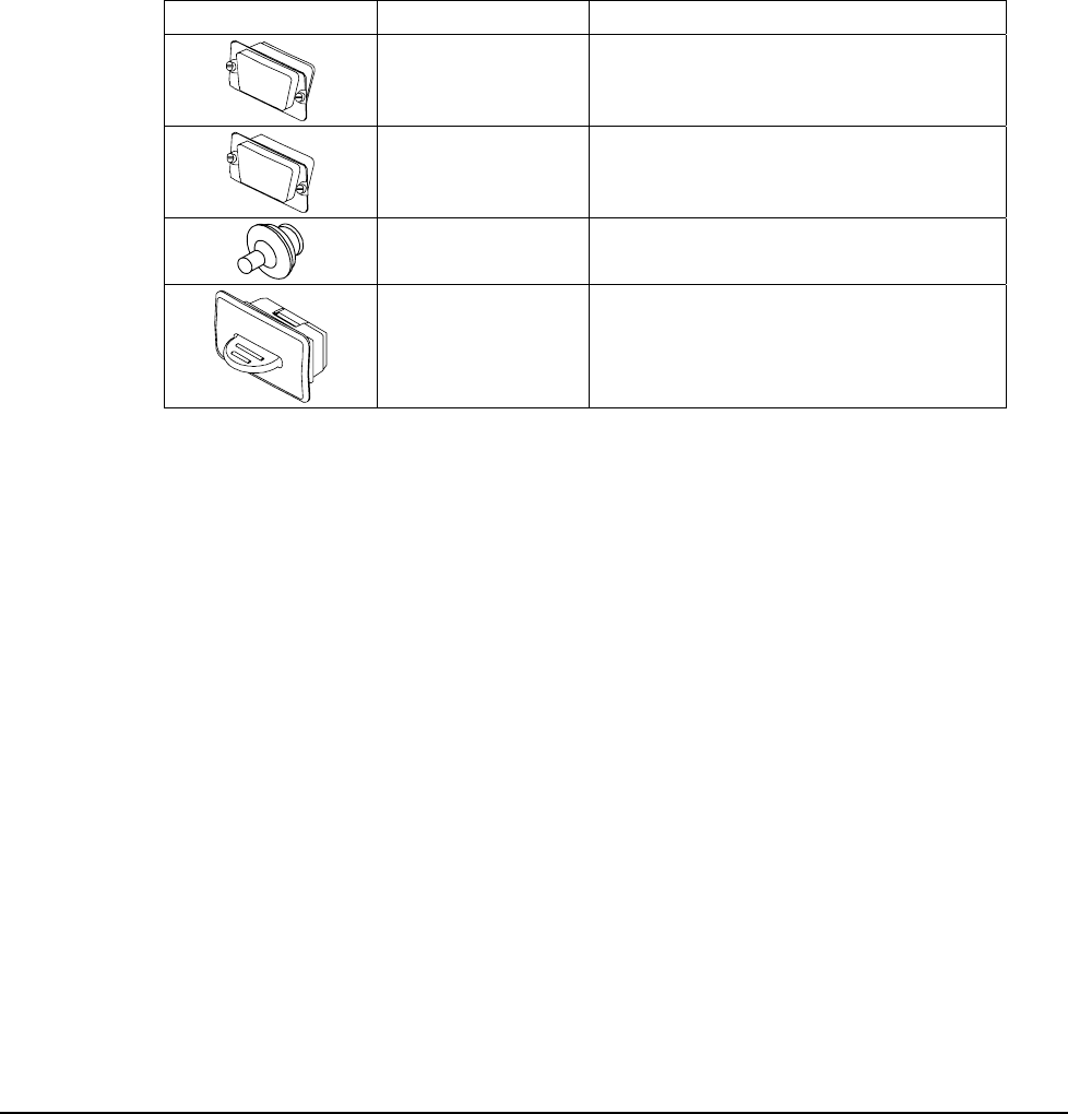
Table 1-1: Connector Covers
Illustration Part Number Description
14555 DE-9 Male Metal Plug
14556 DE-9 Female Metal Plug
14489 Power Plug
14492 JETT•connect Plug
Note: Illustrations are representative and not to scale.
JETT•RFID+ Technical Reference Manual, MAN0352, Rev. A 2-1
Chapter 2: Getting Started
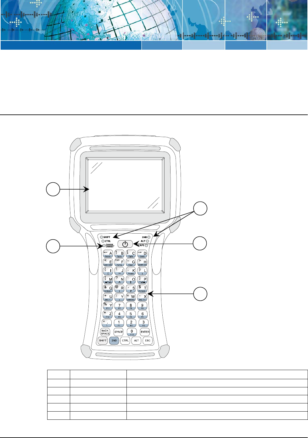
Front Components and Indicators
This section describes the components and indicators found on the font of the JETT.
Figure 2-1: Front Components and Indicators
Table 2-1: Front Components and Indicators
Item Function Description
1 Display Supertwist nematic liquid crystal display with touch screen
2 Battery Indicator Indicates low battery (red) status and charging (green) status
3 LEDs Indicates use of the SHIFT, CTRL, 2ND ALT and CAPS modifier keys
4 On/Off Switch Controls the Power, Suspend and Resume operations
5 Keypad Standard 45-key keypad (30 and 15-key keypads not shown)
1
3
2
5
4
Getting Started
2-2
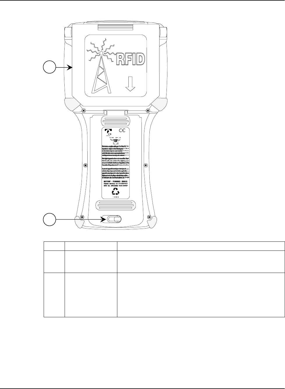
Rear Components
This section describes the components found on the rear of the JETT•RFID+.
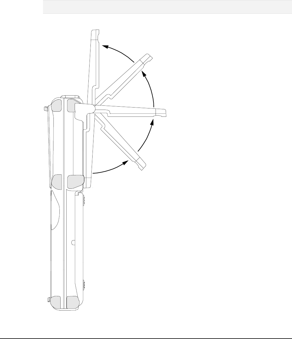
Figure 2-2: Rear Components
OPEN Antenna for
Maximum Range
Table 2-2: Rear Components
Item Function Description
1 RFID+ module The RFID+ module attached to the rear of the unit can read RFID tags
in its storage position (show above) or swing out up to 180 degrees
for maximum range. See Figure 3-11.
2 Battery
Compartment
The battery compartment can store either the Nickel Metal Hydride
rechargeable battery pack or six AA Alkaline batteries. You can
access the battery compartment by lifting up and turning the
retaining clip.
For more information using batteries, see Battery-Powered
Operation.
1
2
JETT•RFID+ Technical Reference Manual, MAN0352, Rev. A
2
-3
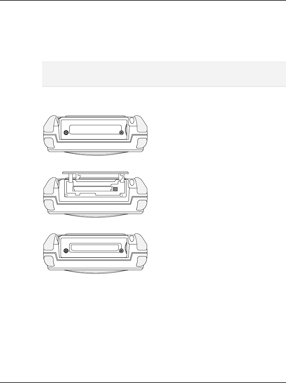
Compact Flash Slot Cover
The standard compact flash slot cover located on the top of the unit provides access to the compact
flash slot that stores memory and device cards. In addition to the standard cover, a modified cover
which has a machined opening that allows you to easily insert and remove devices cards that exceed
1.437 inches in height, is also available.
Two phillips-head screws (2-56 x 5/16”) secure the cover to the top of the JETT. To insert device or
memory cards into the compact flash slot, you must first remove these screws using a phillips # 0 non-
magnetic tip screwdriver, which you can purchase from Two Technologies (Part Number 14673). You
can also purchase additional screws from Two Technologies (Part Number 12624).
Note: JETTs with serial numbers prior to HH276477 use 1-32 x 1/4" long Torx screws. To remove these screws
requires use of an IP6 Torx (T6) driver, which you can purchase from Two Technologies (Part Number 14170)
or McMaster-Carr (Part Number 5259A11). You can also purchase additional Torx screws from Two
Technologies (Part Number 14168) or Camcar (Part Number 3BE-P8240-00).
For more information about inserting and removing memory and device cards, see Using the Compact
Flash Slot.
Figure 2-3: Standard Compact Flash Slot Cover, Closed
Figure 2-4: Standard Compact Flash Slot Cover, Opened
Figure 2-5: Modified Compact Flash Slot Cover for Long Device Cards
Getting Started
2-4
Interface Connections
This section describes the interface connectors found on the bottom of the JETT.
Warning! Do not enable or utilize the RFID+ module with a cable connected. Operation of this nature is
likely to cause harmful interference.
JETT•connect System
The JETT•connect system is a set of rugged interface and cable connectors especially designed for
industrial environments. It features positive connector retention without any hardware restraints for
quick connect/disconnect operations and a contact design that prevents failure due to pin fatigue and
cable stress after repeated use.
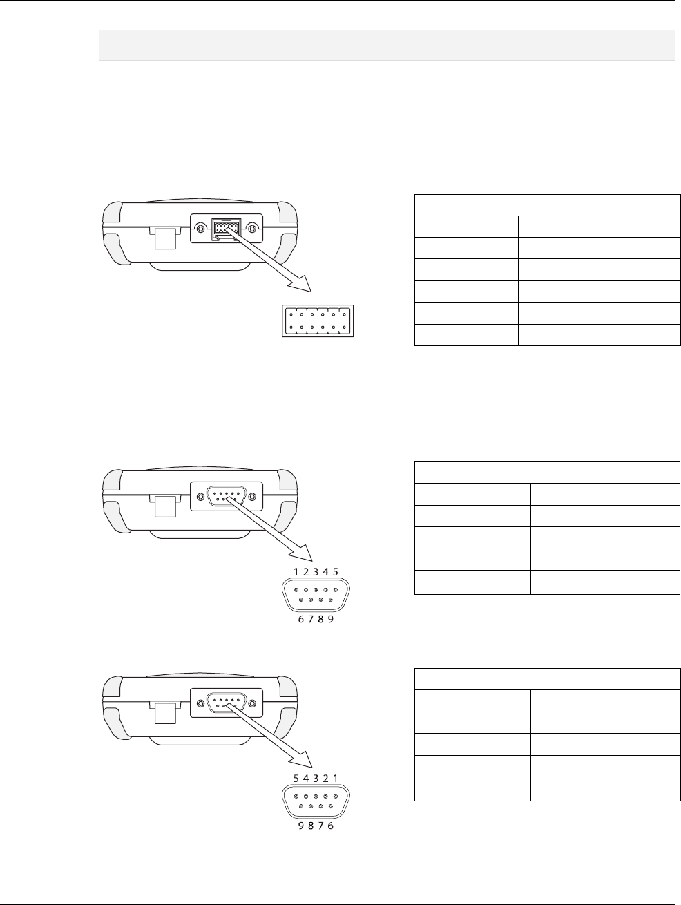
Figure 2-6: JETT•connect Interface Connector
RS-232 Interface Pin-Outs
Pin 1 = X1 Pin 7 = DSR
Pin 2 = Ground Pin 8 = RTS
Pin 3 = RI Pin 9 = DCD
Pin 4 = CTS Pin 10 = 11-18VDC Input
Pin 5 = DTR Pin 11 = Shield
Pin 6 = TXD Pin 12 = RXD
1
2
3
4
5
6
7
81012
911
Viewed facing connector
DE-9 Connectors
The DE-9 connectors emulate standard serial pin-out connections, and allow you to connect the JETT to
most desktop PCs using a standard null modem cable.
Figure 2-7: DE-9 Male Interface Connector
RS-232 Interface Pin-Outs
Pin 1 = DCD Pin 6 = DSR
Pin 2 = RXD Pin 7 = RTS
Pin 3 = TXD Pin 8 = CTS
Pin 4 = DTR Pin 9 = 11-18VDC Input
Pin 5 = Ground
Viewed facing connector
Figure 2-8: DE-9 Female Interface Connector
RS-232 Interface Pin-Outs
Pin 1 = DTR Pin 6 = DTR
Pin 2 = TXD Pin 7 = CTS
Pin 3 = RXD Pin 8 = RTS
Pin 4 = DSR/DCD Pin 9 = 11-18VDC Input
Pin 5 = Ground
Viewed facing connector
JETT•RFID+ Technical Reference Manual, MAN0352, Rev. A
2
-5
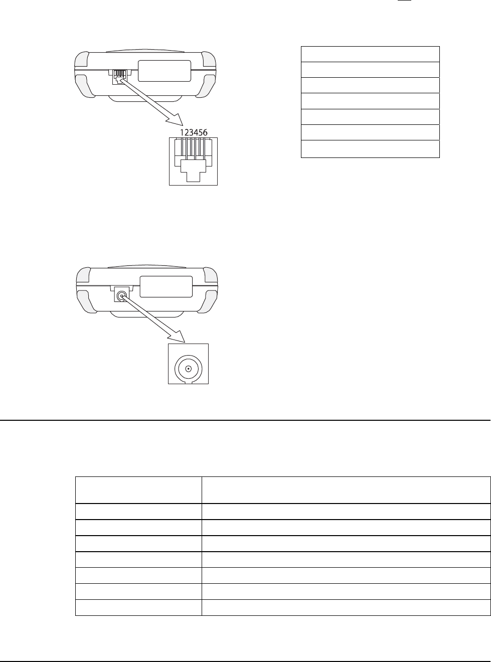
6-Pin Modular Connector
Despite its physical similarity to a telephone jack, the 6-pin modular connector is not compatible with
telephone lines or signals. Connecting the JETT to a telephone line will damage it and void the
warranty.
Figure 2-9: 6-Pin Modular Interface Connector
RS-232 Interface Pin-Outs
Pin 1 = 11-18 VDC Input
Pin 2 = CTS
Pin 3 = RTS
Pin 4 = RXD
Pin 5 = TXD
Pin 6 = Ground
Viewed facing connector
Power Jack
The optional power jack found on the bottom of the JETT enables you to connect an 11-18 VDC Input
power supply battery charger, such as Two Technologies #14508. Use of other power supplies unless
approved by Two Technologies may cause damage to the unit and void the warranty.
Figure 2-10: Power Jack
Viewed facing connecto
r
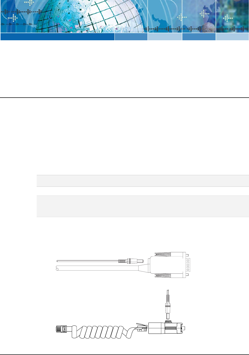
Power Supplies, Cables and Adapters
Two Technologies can provide the following optional power supplies, cable and adapters based on
communication and power requirements. For cable signal and pin assignments, see Appendix B: Signal
and Pin Assignments.
Table 2-3: Available Power Supplies, Cables and Adapters
Two Technologies
Part Number
Part Description
14508 11–18VDC Power Supply (North America Only) 1
91708 Black, 15-Foot JETT•connect Cable (DE-9 Male)
91709 Black, 15-Foot JETT•connect Cable (DE-9 Female)
1210-7-BK Black, 7-Foot Coiled Modular-to-Modular Cable
1210-15-BK Black, 15-Foot Coiled Modular-to-Modular Cable
14375 Black, 15-Foot Null Modem Cable (DE9 Female to DE9 Female)
CELAT-P Modular Cable to DE-9 Cable Adapter
1. Use of other power supplies unless approved by Two Technologies may cause damage to the unit and void the
warranty.
JETT•RFID+ Technical Reference Manual, MAN0352, Rev. A 3-1
Chapter 3: Operation
Power
The JETT comes with a rechargeable Nickel Metal Hydride (NiMH) battery pack that can provide up to
twelve hours of operating time on a full charge (depending on power management and use). This
battery is fully charged and installed in the unit when shipped. However, because some battery
dissipation occurs between the time when the unit ships and when you start using it, you should charge
the unit for approximately four hours before using it without the battery charger/power supply
connected.
Charging the Unit
The nickel metal hydride battery technology used in the JETT has exceptional charge life without the
“charge memory” characteristic of conventional nickel cadmium batteries. Partially discharged batteries
or extended periods with the charger left connected will not adversely affect battery life or per-
formance.
Warning! Do not enable or utilize the RFID+ module while charging the unit. Operation of this nature is likely
to cause harmful interference.
Note: Because the internal battery charger senses several conditions, including temperature, you should
charge the unit away from any known or potential heat sources. Units exposed to temperatures in excess
of 110 degrees Fahrenheit during the charge cycle may experience incomplete charging and reduced
operating time per charge.
To charge the NiMH battery pack:
1. Depending on your configuration, plug the power jack of the battery charger/power supply
into the corresponding cables connector and/or adaptors as shown below.
Figure 3-1: Using 91708, 91709, and14375 Cables
Power Supply/Battery Charger
To Unit
Figure 3-2: Using 1210 Series Cables
Power Supply/Battery Charger
To Unit CELAT-P Adaptor
Operation
3-2
2. Plug the interface cable into the connector on the bottom of the JETT. If your unit has a power
jack receptacle on the bottom of your JETT, just plug the power jack into that receptacle.
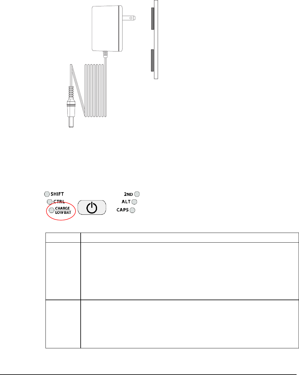
3. Plug the battery charger/power supply into a power outlet. The Charge LED should turn on,
indicating that the batteries are charging (see Table 3-1).
Figure 3-3: Power Supply
4. Once the battery is fully charged (approximately four hours), you can disconnect the AC
power supply and run the JETT exclusively on battery power.
Charge/Low Battery Indicator
When using the NiMH battery pack, the CHARGE/LOW BAT LED will indicate the current battery
status as shown in the table below.
Figure 3-4: Charge/Low Battery Indicator
Table 3-1: Charge\Low Battery Indicator Functions
Function Description
CHARGE With the power supply connected, the CHARGE/LOW BAT LED will indicate one of
following conditions:
High Power Charge—the LED will turn solid green
Fully/Near Full Charge—the LED will blink green about four times a second
Trickle Charge—the LED will blink green approximately once per second
when either the battery voltage and/or temperature of the battery assembly
are not within acceptable limits
LOW BAT With the power supply disconnected, the CHARGE/LOW BAT LED will indicate one
of following conditions:
Batteries are low— the CHARGE/LOW BAT LED will blink red once per
second when there is approximately 30 minutes of power remaining
Batteries are very low—the CHARGE/LOW BAT LED will turn solid red
when there is approximately 10 minutes of power is remaining
JETT•RFID+ Technical Reference Manual, MAN0352, Rev. A 3-3
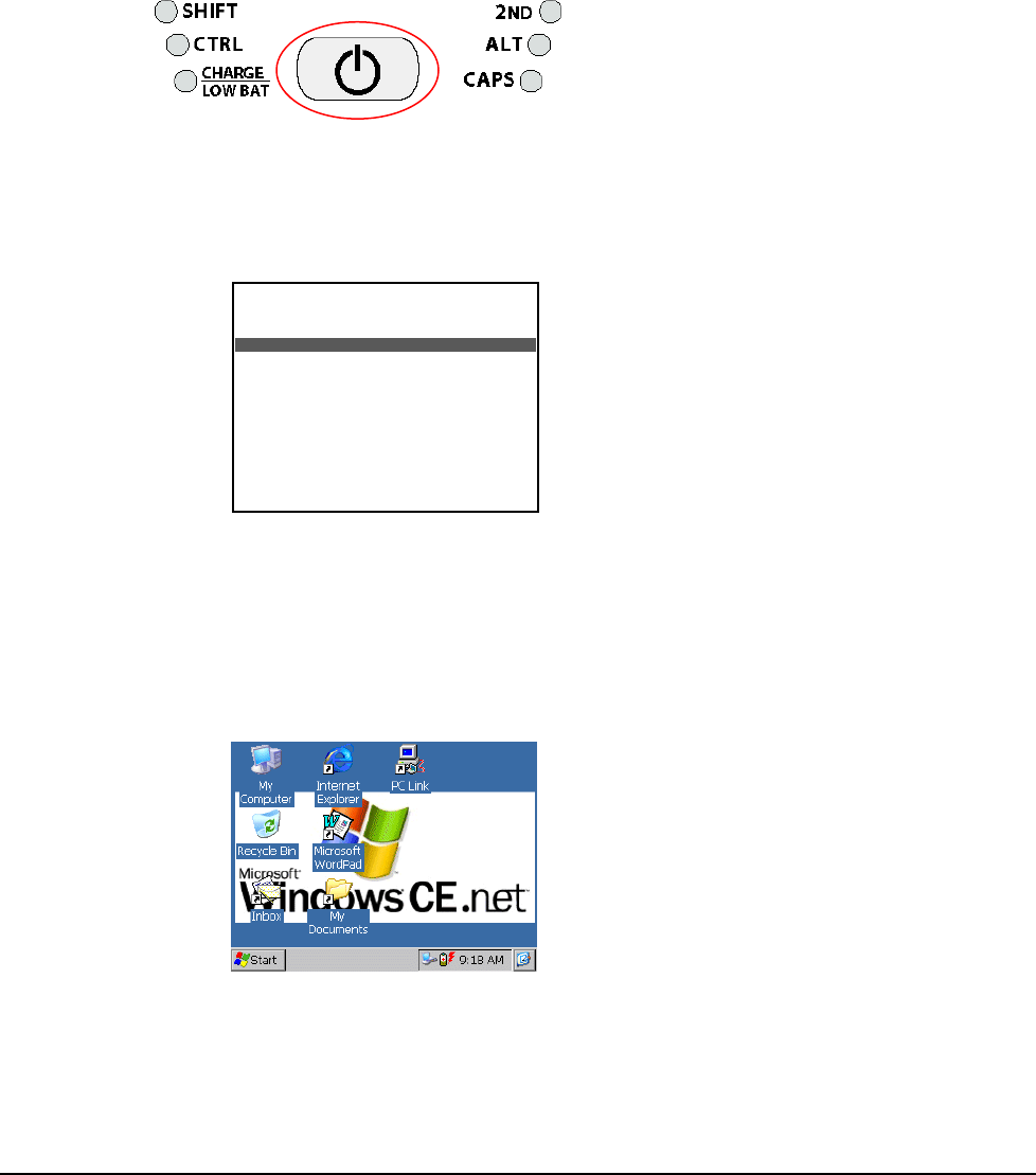
Power/Suspend Switch
The On/Off switch is located above the keypad. Its function depends on the state of the JETT at the
time the switch is pressed and on the length of time that the switch is depressed. Operations that the
Power switch can initiate are:
• Power On
• Power Off
• Suspend
Figure 3-5: Power/Suspend Switch
Power On
To power on the JETT:
1. Press and hold the ON/OFF switch for one second.
2. The unit should turn on and begin displaying the boot-up process. For example:
Where x.x.x is the version number
3. After approximately 20-25 seconds, the Windows CE .NET desktop should appear.
However, because there is no outward indication (such as a flashing LED) that the JETT is
powered off or in Suspend mode, the JETT may resume an active application if it is indeed in a
suspended state.
If the unit does not power up or you cannot select any items from the desktop, refer to the
“Troubleshooting” chapter for help.
***** JETT.ce *****
Loader Ver x.x.x
Booting nk.gz from System Socket
Reading gzip file from SYSTEM Socket
##########################################
Loading CE Image...
###

Operation
3-4
Power Off
To turn off the JETT, press and hold the ON/Off switch for approximately eight seconds. This action
will also terminate running applications and cease serial port operations).
Suspend Mode
Suspend mode allows you to suspend, but not terminate active applications. In this mode, the display
will turn off and the JETT will cease serial port operations. For battery-powered units, use of Suspend
mode also conserves battery power.
To place the unit in Suspend mode, press and release the ON/Off switch.
To take the JETT out of Suspend mode, either touch the screen or press and release any key. The display
will turn on and the JETT will resume running any suspended application, but you must restart any
serial port operations.
If you attempt to resume immediately after suspending the JETT or vice versa, the unit will
automatically delay three seconds before resuming or suspending.
Power Management
Battery-powered units can utilize a rechargeable Nickel Metal Hydride (NiMH) battery pack that has an
average operating time between ten and twelve hours on a full charge with power management and
approximately eight hours without power management. As with all battery-powered devices, the
operating time is completely dependent on the environment, device usage and the number and type of
power-drawing peripherals attached. The battery discharge rate in a full “Power Off” state is only
slightly higher to the self-discharge rate of the battery itself.
Note: Allowing the batteries to remain in a low or very low condition will cause the unit to enter Suspend
mode. In either case, you should save your work and recharge the unit as soon as possible
To lengthen the time between charges, you can perform the following actions:
• Use external power for PC Card operations whenever possible— some PC Cards as well as
extended communication via the serial port, may require large amounts of power to operate,
and can quickly drain the batteries.
• Limit the use of backlight—minimize backlight use when you are operating on battery
power. You can adjust the backlight timeout level through the Display Settings in the Control
Panel or on some units by using the keypad.
• Shorten Auto-suspend time—the JETT is automatically set to suspend operation to conserve
battery power when you have not used the keyboard or the stylus after three minutes. You can
increase the Auto-suspend time by changing the Power settings in the Control Panel.
JETT•RFID+ Technical Reference Manual, MAN0352, Rev. A 3-5
Replacing Batteries/Battery Pack
CAUTION! There is a risk of explosion if you replace the NiMH battery with an incorrect type. Only use the
NiMH battery supplied with your unit or a replacement NiMH battery supplied, recommended, or
approved by Two Technologies, Inc.
When using alkaline batteries, replace all alkaline batteries in the JETT at the same time. Do not mix old
and new batteries, mix different types or brands of batteries, or dispose of the batteries in a fire. These
actions can cause battery rupture or leakage that result in personal injury or property damage.
Remove the batteries from the JETT when not using the JETT for extended periods. Store the batteries in
a cool, dry location at normal room temperature.
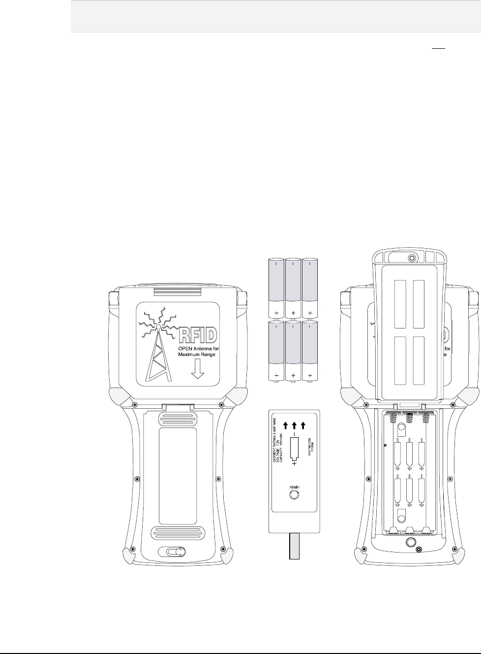
To replace the rechargeable battery pack or change AA batteries:
1. Turn the power off. With the unit face down, pull the battery cover retaining clip up from its
recessed slot and turn the clip in a counter clockwise motion (see Figure 3-6).
2. Lift the cover up and remove the batteries/battery pack.
3. If the unit contains a NIMH battery pack, use the tab to lift up on the battery pack and then
out.
4. Close the battery cover and turn the battery cover retaining clip clockwise to lock the cover.
Figure 3-6: Changing Batteries
TOP
PLEASE RECYCLE
BOTTOM
CAUTION:
RISK OF EXPLOSION IF BATTERY
IS REPLACED BY AN INCORRECT
TYPE. DISPOSE OF USED BATTER IES
ACCORDING TO THE INSTRUCTIONS.
Battery Pack Cover
(opened)
NiMH
Battery Pack
Tab
Akaline Batteries
Battery Pack Cover
(closed)
Retaining Clip

Operation
3-6
Data Entry
Keypads
45-Key Keypads
In order to provide the functionality of a full-sized keyboard with only 45 keys, the JETT keypad must
depart from PC-style key assignment conventions by making use of modifier keys. Units configured
with the standard 45-key keypad typically utilize five LED indicators (located above the ON/OFF
switch) to indicate the active state of keypad modifier keys. Units with 45-key keypads also have
keypad functions to adjust the contrast and backlight.
30-Key Keypad
Units with a 30-key keypad provide a full complement of alphabetical characters. Users can access
numeric characters, punctuation characters, navigation keys and backlight control via the SHIFT key.
15-Key Keypad
Typically, units shipped with a 15-key keypad have custom keyboard layouts geared toward specific
applications that must be loaded onto the unit. To provide you a method of navigating and using
Windows CE .NET until you configure and map your keypad in the context of your application using
Kbtool. Two Technologies provides a template that shows the default functions (see figure below).
Figure 3-7: Standard Keypad Layouts
G
A
Delete B
PgUp C
PgDn D
Insert
E F
Home H
I
{J
~
KL
}
<END _>
^
Pause
(!;)
[?']
RST
#
Q
&@$
U
+V
,
/X
BKLT +
-
W
=
Y
%7
F7
9
F9
8
F8
Z
*4
F4
6
F6
5
F5
.
\
1
F1
2
F2
3
F3
0
F10
BACK
SPACE SPACE ENTER
SHIFT 2ND CTRL ALT ESC
BKLT -
"
Clear
OMN P
Tab Tab
,
WMENU
F11
F12
|
45-Key Keypad
SHIFT
ALT ESC
0
BACK
SPC SPC ENTER
798
*
465
123
U
+
V
,
/
X
BKLT
+
-
W
BKLT
-
Z
Y
G
ABC
DEF
HI
JKL
?
R
ST
Q
OMN
P
TAB
:
30-Key Keypad
TAB ALT
\
-+
ESC .ENTER
2ND CTRL
Back
Space
SPACE
15-Key Keypad

JETT•RFID+ Technical Reference Manual, MAN0352, Rev. A 3-7
Modifier Keys
The following modifier keys (located on the bottom of a standard keypad) enable you to access the
various functions that can appear on a key. Figure 3-8 provides an example.
Figure 3-8: 45-Keypad Multifunctional Key
A
Delete
Modifier keys take effect when first pressed and typically remain in effect until you press another key,
unless its another Modifier key (see Table 3-2). Optionally equipped units can use LEDs to indicate the
selection of a Modifier key.
• CTRL and ALT Keys—operate in the same manner as on conventional PCs, except that by
default they have a one-time locking action to facilitate one-handed operation.
• SHIFT Key—unlike conventional PC keyboards, the SHIFT key enables you to access symbols,
punctuation marks and navigation arrows rather than shift alphabetic keys to uppercase.
On standard JETT keypads, the functions and characters accessed via the SHIFT key appear in
the upper left of a key (shaded in gray in Figure 3-8).
By default, the SHIFT key has a one-time action. However, you can press the Shift key twice
and lock the keypad into Shift mode, wear each subsequent key press will only access
characters that appear in the upper left of a key. Pressing the Shift key a third time will release
Shift mode.
• 2ND Key— shifts the numeric keys to corresponding function keys (1 = F1, 2 =F2, etc.) that are
found on conventional PC keyboards.
It also shifts other keys for punctuation, non-printing characters (such as Delete and TAB), and
PC key definitions (such as PageUp, PageDown, Home, Insert and Caps Lock).
On the standard JETT 45-key keypad, the functions and characters accessed via the 2nd key
appear at the bottom of a key, (shaded in blue in Figure 3-8).
Like the Shift key, the 2ND key has a default one-time action and a locking mode (i.e., pressing
the 2ND key twice will lock the keypad into 2ND mode).
Table 3-2: Modifier Key Actions
Key Presses Result
A Lowercase “a”
Shift & A Move cursor left one position
2ND & A Delete Character
2ND & Caps Lock Uppercase “A”
Key Repeat
By default, the JETT does not automatically repeat a key stroke when you hold down a key. However,
you can enable the key repeat function by configuring the Keyboard setting in the Control Panel.
Operation
3-8
CE Keyboard
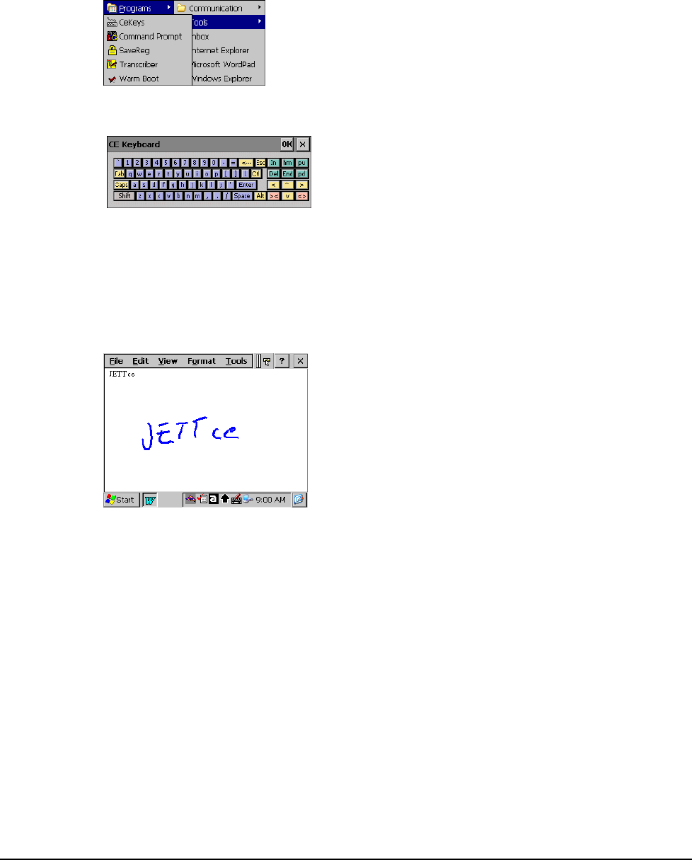
In addition to entering data through the keypad, you can also enter data by using the CE Keyboard.
This utility displays a keyboard on the screen to allow data entry via the Command Line or into
applications where “text accessibility” control has focus (i.e., text or combo box).
To use the CE Keyboard, select Programs > Tools> CeKeys from the Start menu.
To minimize the keyboard, click the keyboard icon that appears in the system tray
Figure 3-9: CE Keyboard
Transcriber
Microsoft Transcriber is a natural handwriting recognition software program that interprets pen
movement across the screen as handwriting (cursive, print or mixed) input. For more information,
please refer to Microsoft Transcriber Help on the JETT.
To run Microsoft Transcriber, select Programs > Tools> Transcriber from the Start menu.
Figure 3-10: Transcriber
JETT•RFID+ Technical Reference Manual, MAN0352, Rev. A 3-9
Using the RFID+ Module
The RFID+ module can read and write (up to 16k bits) most industry standard 13.56MHz RFID tags and
smart labels including for 13.56MHz RFID tag types. See Appendix D for supported tag formats.
The RFID+ module is totally application dependent and derives power from the COM2 port. The
RFID+ module has a flip-out antenna that provides a read range of approximately 3.5 inches (90mm)
with a credit card size tag at 90 degrees (see illustration below). For optimal tag reading performance,
adjust the module to either 90° or 180°.
For RFID+ module application integration information, contact Two Technologies.
Warning! Do not enable or utilize the RFID+ module with a cable connected. Operation of this nature is
likely to cause harmful interference.
Figure 3-11: RFID Read Range
0º
180º
90º
Operation
3-10
The Windows CE .NET Desktop
This section provides a brief overview of the functions that appear on the JETT desktop. For
information on how to change desktop settings, refer to Windows CE .NET help (Start > Help).
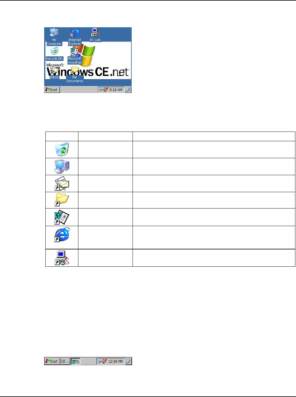
Figure 3-12: Windows CE .NET Desktop
Desktop Functions
You can access the following applications, functions and data entry utilities from the JETT desktop:
Table 3-3: Desktop Functions
Icon Function Description
Recycle Bin Use the Recycle Bin to restore deleted files or empty the bin to
create more disk space.
My Computer Use My Computer to navigate and view the folders and files
stored on the JETT.
Inbox Use the Inbox to send and receive e-mail by connecting to a
POP3 or IMAP4 server.
My Documents The default storage location for documents, graphics, and other
files.
Microsoft WordPad Use WordPad to create or edit text files that contain formatting
or graphics.
Internet Explorer Use Internet Explorer to view Web pages. You will need a
modem or Ethernet card to connect to an Internet service
provider (ISP) or network.
PC Link Use PC Link to make an ActiveSync, Bluetooth or other type of
connection to another device
The Taskbar
The taskbar at the bottom of the JETT desktop displays the Start button, buttons of currently running
applications, the Status Area and the Show Desktop icon.
Tap the Start button to display the Start menu (see below for details). For each open application, a
button appears on the taskbar. Simply tap the button to activate the application.
The status area appears on the right and by default displays small icons for the input panel, current
time, power status and network connections. Tap an icon to activate the related program.
Tapping the Show Desktop icon minimizes active applications and redisplays the desktop. Tapping the
Keyboard icon displays the Input Panel menu for data entry.
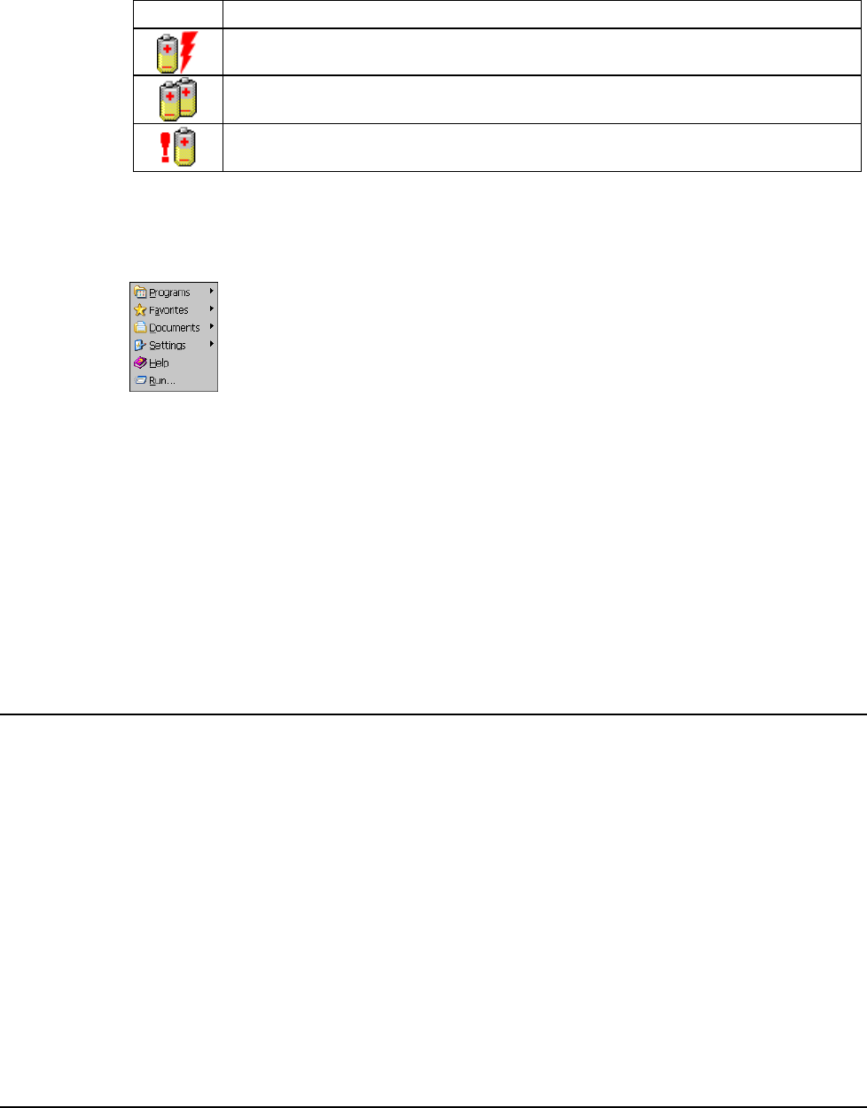
Figure 3-13: Windows CE .NET Desktop Taskbar
JETT•RFID+ Technical Reference Manual, MAN0352, Rev. A 3-11
Power Status Icons
The JETT will display power status icons (Table 3-4) in the taskbar status area (Figure 3-13) to indicate
power use, charging status and low battery conditions.
Table 3-4: Power Status Icons
Icon Description
Batteries are charging
Batteries are low—approximately 30 minutes or less of use remaining (the
CHARGE/LOW BAT LED will blink red once per second)
Batteries are very low—approximately 10 minutes or less of use remaining (the
CHARGE/LOW BAT LED will turn solid red)
The Start Menu
When you tap Start, the Start menu appears.
Figure 3-14: Start Menu
By tapping one of the menu’s icons (and not the name), you can:
• Open programs that do not appear on the desktop
• View a list of web sites added to your Favorites List
• View recently accessed documents and images
• Access the Control Panel, establish connections, or configure the Taskbar and Start Menu
• View Help
• Start an application using the Run command
• Place the unit in Suspend mode
SystemCF Folder
The only folder that provides non-volatile (permanent) storage is the SystemCF folder. Information
stored in other folders will be lost when you remove power from the JETT. You can however, have the
JETT automatically copy files from the SystemCF to other folders when booting up. See Launching Files
at Startup for more information.
JETT•RFID+ Technical Reference Manual, MAN0352, Rev. A 4-1
Chapter 4: Configuration
The Control Panel
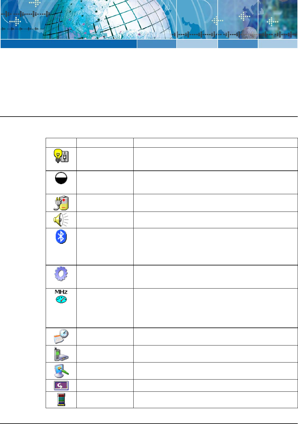
The table below lists the available control panel functions on the JETT.
Table 4-1: Control Panel Functions
Icon Function Description
Aux Switch For units with a second COM that supplies 5VDC output, use
this function to set the default power state (On or Off), and test
the connected devices.
Backlight Use this function to adjust the backlight setting for the following
conditions: Line Active, Line Active Inactive, Battery Active and
Battery Inactive.
Battery Select Select one of the following options to calibrate the power status
icons for proper use: NIMH, AC Line or Alkaline.
Beep Select Use this function to change the frequency, volume and duration
properties of the beep.
Bluetooth Device
Properties
Use this function to scan for other Bluetooth devices and services
in the area when using optional Bluetooth cards (except those
manufactured by Socket Communications, Inc. Refer to the
JETT•ce Bluetooth Setup and Configuration Guide for more
information.
Certificates Use this function to import, view or remove certificates, which
protect your personal information on the Internet, and protect
your computer from unsafe software.
CPU Speed For units with 400 MHz processors, use this function to
determine the CPU speed (200 or 400 MHz) and mode (Turbo
and Non-Turbo) during runtime and cold boot-up.
Turbo Mode allows you to clock the processor core at a higher
frequency during peak processing requirements.
Date/Time Use this function to adjust the date, time and time zone.
Dialing Use this function to adjust the dialing location settings and
dialing patterns when using a modem.
Display Use this function to adjust the backlight timeout, change the
background image or change the desktop color scheme.
Display Rotation Use this function to rotate the screen 180 degrees (upside down).
Hot Keys Use this function to assign functionality to the unit’s eight
programmable keys (requires Keyboard Mapping).
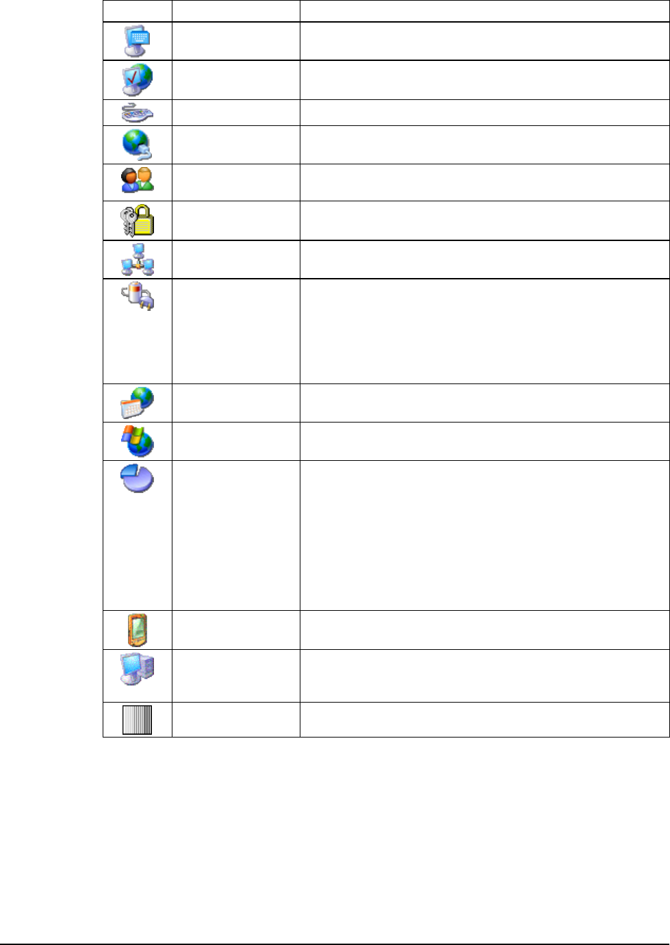
Configuration
4-2
Icon Function Description
Input Panel Use this function to adjust the settings for the input panel.
Internet Options Use this function to set up connections, security settings and
internet related functions.
Keyboard Use this function to change the repeat delay and repeat rate.
Network and
Dial-up Connections
Use this function to change network adapter settings and/or set
up identification for remote networks.
Owner Use this function to enter the owner name, address, phone
numbers and network ID.
Password Use this function to enable password protection and set a
password.
PC Connection Use this function to enable direct connection to a desktop
computer
Power Use this function to:
Check battery power
Set device to turn off when idle
Set up power schemes
Check the power levels of your system devices
Regional Settings Use this function to change the appearance of region specific
information, such as date, time and currency.
Remove Programs This function enables you to remove programs installed in RAM.
Storage Manager This function enables you to perform the following tasks:
• View partition information
• Format a partition
• Create or delete a partition
• Mount or dismount a partition
• Scan and repair a partition.
• Defragment a partition
Stylus Use this function to recalibrate the touch screen and adjust the
stylus double-tap rate.
System Use this function to view system information, change the RAM
(Program/Storage memory) division, change the device name
and change the device description..
VComAdj Use this function to minimize screen flicker and adjust contrast.
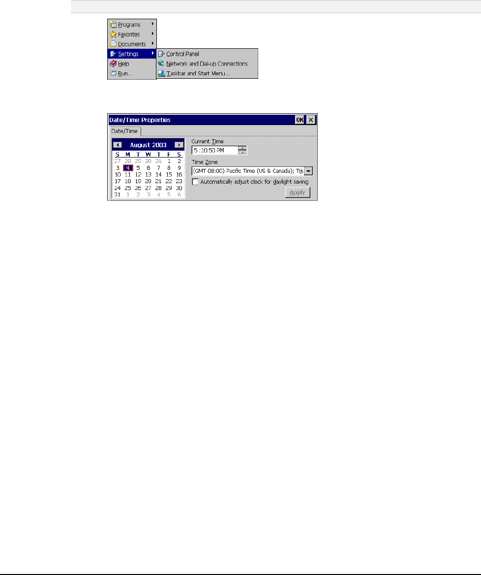
JETT•RFID+ Technical Reference Manual, MAN0352, Rev. A
4
-3
Changing System Settings
Any time you make changes through the Control Panel (such changing the time zone), you must also
update the persistent registry to store the changes in internal compact flash memory to make the
changes permanent.
For example, to change the time zone and save the changes to the registry:
1. Select Start > Settings > Control Panel.
Note: Tap the icon, not the name.
2. On the Control Panel, double-tap Date/Time. The Date/Time Properties dialog box appears.
You can now set the date, time and time zone.
3. To adjust the Current Time, use the scroll bars to increase or decrease the value, or tap hours,
minutes, seconds or AM/PM indicator to set the values individually.
4. To select the Time Zone, use the corresponding list.
5. To adjust the Date, either:
Tap the arrows on the calendar to select the previous/next month
Double-tap the month or year to select it from a list
Tap a day to select it
6. To adjust the clock automatically for daylight savings, check the corresponding box.
7. Tap Apply to have your setting take effect.
8. Tap OK to close the Date/Time Properties dialog box and return to the Control Panel.
9. Tap OK to exit the Control Panel.
10. From the Start menu, select Programs> Tools> SaveReg.
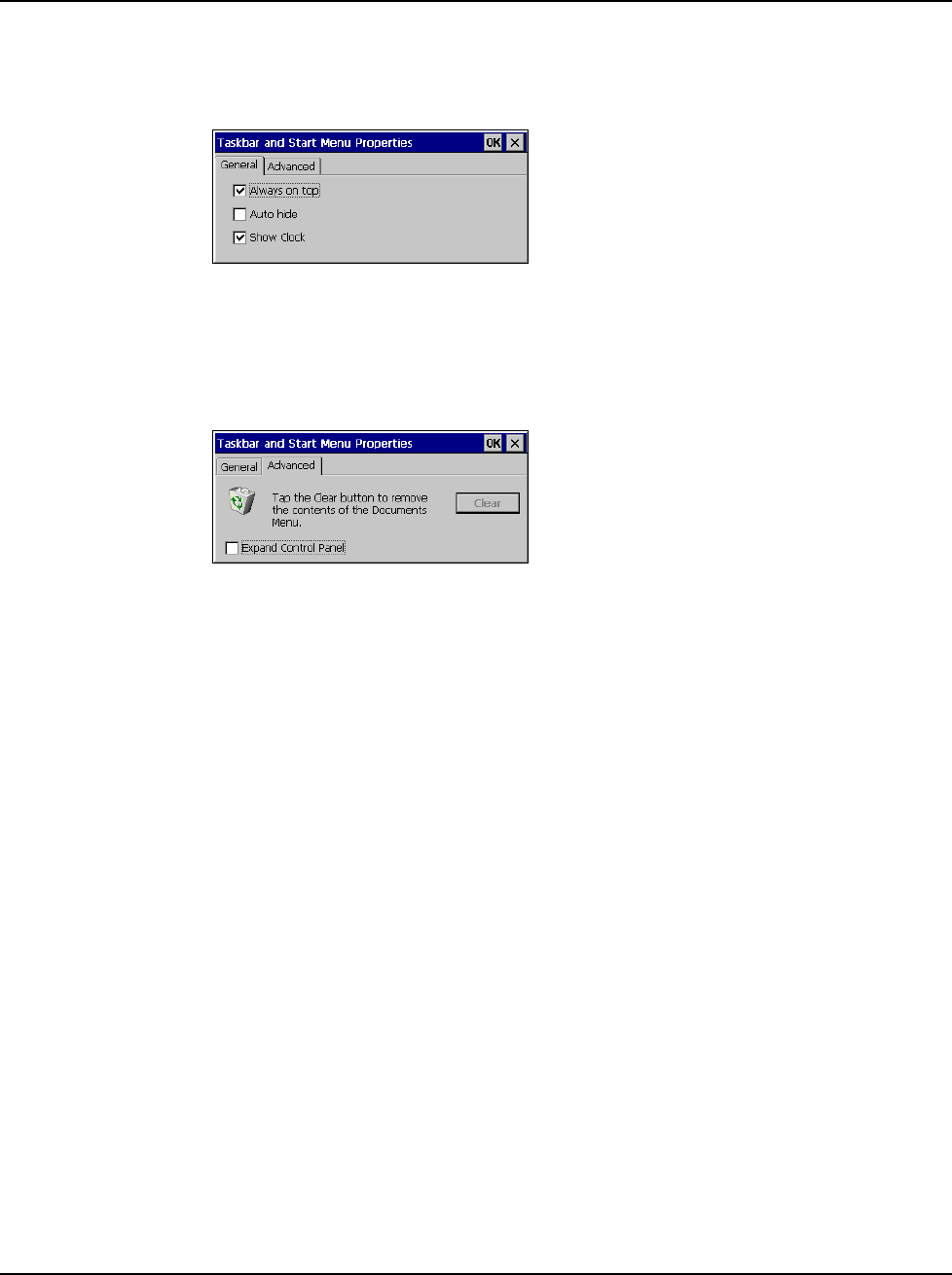
Configuration
4-4
Taskbar and Start Menu Settings
To change the Taskbar and Start Menu settings:
1. Select Start > Settings> Taskbar & Start Menu. The Taskbar and Start Menu Properties dialog
box opens:
2. Select the General tab:
3. Check Always on Top to ensure that the taskbar is always visible, even when a program
appears in a full window (maximized).
4. Check Auto hide to display the taskbar just when you point to the taskbar area.
5. Check Show Clock to display the time of day in the taskbar.
6. Select the Advanced tab:
7. Tap the Clear button to remove the contents of the documents menu.
8. Check the Expand Control Panel box to display the contents of the Control Panel as items on
the Settings| Control Panel menu.
9. Tap OK to save the settings and exit the menu.
10. From the Start menu, select Programs> Tools> SaveReg.
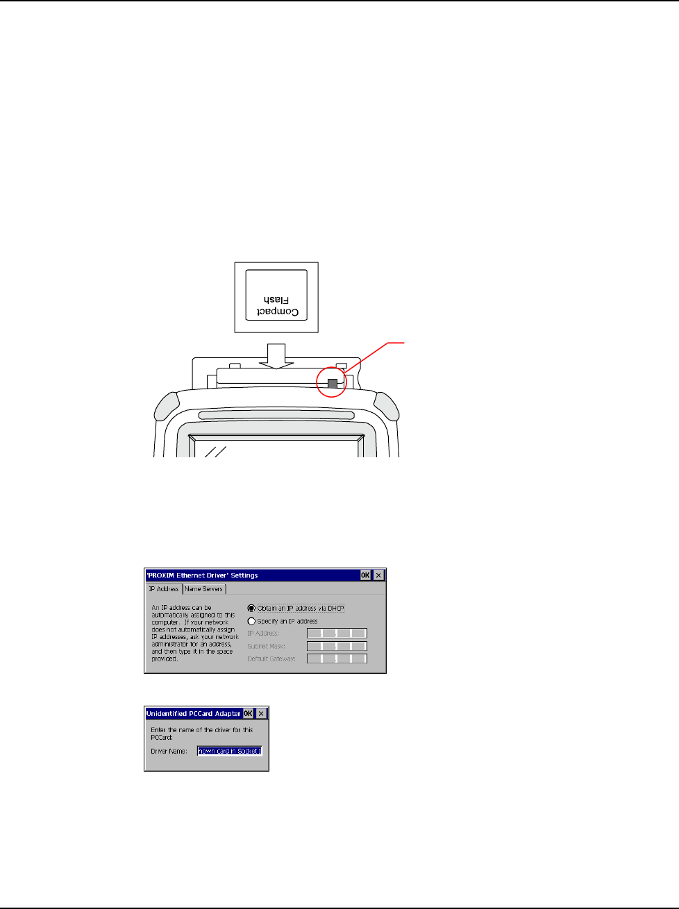
JETT•RFID+ Technical Reference Manual, MAN0352, Rev. A
4
-5
Using the Compact Flash Slot
The Compact Flash Slot located on top of the JETT enables you utilize a variety of devices such as
memory cards, barcode scanners, GPS cards and network cards.
If you intend to use a device card, it may also be necessary to install a driver. If so, make sure the card is
Windows CE .NET 4.2 compatible and you have the necessary drivers. If you are not sure, check with
the card manufacturer before attempting to install the card.
To use the compact flash slot:
1. If needed, remove any screws from the cover to access the Compact Flash slot. Refer to the
“Compact Flash Slot Cover” section for information about cover and screw types.
2. With the front of the display facing you, push the compact flash slot cover to the left. The slot
cover will automatically pop open. If the cover has a slot, you can skip this step.
3. Insert the compact flash/device card into the slot with the front of the display facing you and
the top of the card pointed to the slot until it clicks and the release lever moves upward.
Figure 4-1: Using the Compact Flash Slot
4. Close the cover.
5. When inserting memory cards, a “UserCF” folder will appear when you open My Computer.
You can then copy and paste the contents of UserCF to the other folders on the JETT.
6. When inserting device cards, the JETT will attempt to recognize the device. If it finds a driver
for the device, the JETT will display a dialog box for that device. For example:
If the JETT cannot find a driver for the device, it will display the following dialog box:
7. If the correct card type appears, you can enter the appropriate information in the dialog box as
required and then tap OK to complete the installation.
8. To remove a card from a slot, simply push the card release lever down and remove the card.
Release Lever
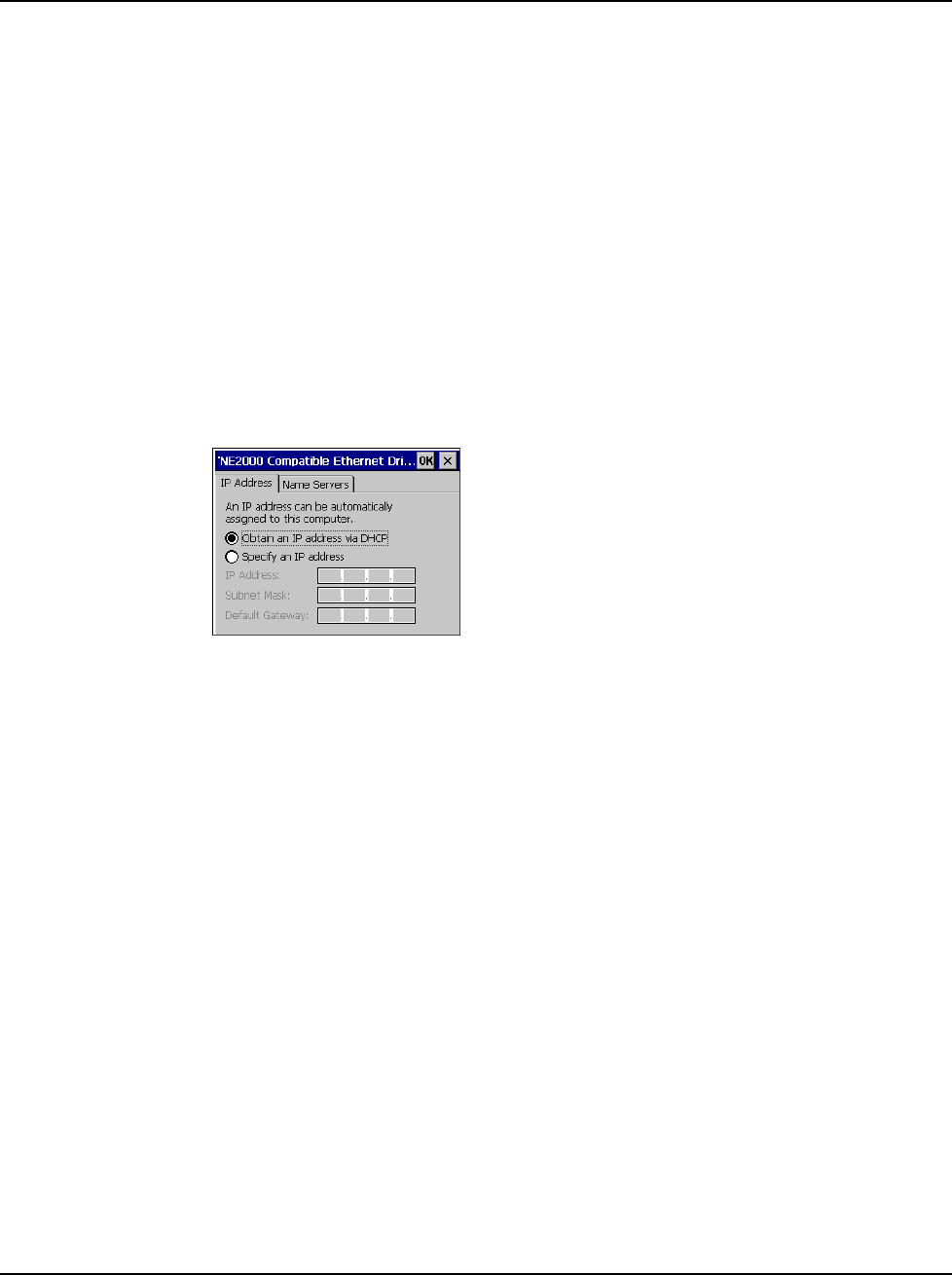
Configuration
4-6
Network Connections
You can connect directly to a network using one of the following card types to access e-mail, access files
available on the network server, and browse the Internet:
• Wired Ethernet CF Card
• WLAN 802.11b CF Card
• Bluetooth Class 1 CF Card
• Bluetooth Class 2 CF Card
Creating a Wired Ethernet Network Connection
To create a Wired Ethernet connection:
1. Insert the Ethernet card into the JETT and connect the cable to the network.
2. Select Start > Settings > Control Panel. Double-tap Network and Dial-Up Connections.
3. Double-tap the connection icon for the adapter. For example, if you have a NE2001 Ethernet
adapter, double-click the NE2001 connection icon.
4. In the Ethernet Driver Settings dialog box, select Obtain an IP address via DHCP and tap OK.
5. If prompted, enter the User Name, Password, and Domain name you use to log on to your
network.
6. From the Start menu, select Programs> Tools> SaveReg.
Creating a Wireless Connection
To create a network connection using a wireless or Bluetooth CF card, refer to either the JETT•ce
Wi-Fi Setup and Configuration Guide, Document Number: MAN034 or the JETT•ce Bluetooth
Setup and Configuration Guide, Document Number: MAN0342.
Setting Up Identification for Remote Networks
To set up identification for remote networks:
1. Select Start > Settings > Control Panel.
2. Double-tap Owner.
3. In the Network ID tab, enter the user name, password, and domain name you use to log on to
the remote network.
4. From the Start menu, select Programs> Tools> SaveReg.
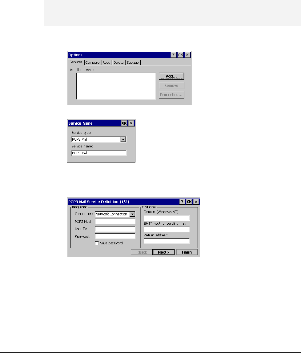
JETT•RFID+ Technical Reference Manual, MAN0352, Rev. A
4
-7
Connecting to a Mail Server
You can send and receive e-mail by connecting to a POP3 or IMAP4 server. Inbox contains an e-mail
service for each method you use. For either service, you must establish a connection to your Internet
service provider (ISP) or to the appropriate mail server in your local area network. In addition to
creating this connection, you must also create the e-mail service.
Prior to setting up a service, you should obtain the following information from your ISP or network
administrator: POP3 or IMAP4 server name, SMTP host name, user name, password and domain name
(for network connections only).
Notes: Windows CE .Net does not support other mail protocols such as AOL or services that use special
authentication, such as MSN. However, you can gain access to the Internet through these services. If you
use the same service to connect to different mailboxes, set up and name a different service for each
connection. For additional information about the inbox, refer to Windows CE .NET online help.
To connect to your POP3 or IMAP4 mail server:
1. Select Start > Programs > Inbox > Services > Options. The Options dialog box opens.
2. Select the Services tab and tap Add. The Service Name dialog box opens.
3. From the Service type list, select POP3 Mail or IMAP4 Mail.
4. Enter a unique name for the service (you cannot change this name once entered).
5. Tap OK. The Mail Service Setup wizard appears.
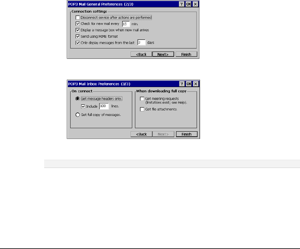
Configuration
4-8
6. In the Required panel:
Select the name of the connection you created to connect to the mail server. If you are
receiving e-mail through a network (Ethernet) connection, select Network Connection.
If you want Inbox to use your current connection, select (none).
If you have not created a connection, select Create new connection, double-tap the Make
New Connection icon, and follow the instructions in the wizard. When finished, select
Inbox in the Taskbar and continue setting up Inbox.
Enter the POP3 Host or Server (IMAP4) name of the mail server you use to receive and
send messages.
Enter the User ID (user name or mailbox ID) assigned to you.
Enter the password you will use to access this mail account. If you do not want a prompt
to enter the password each time you connect, select Save password.
7. In the Optional panel:
If connecting to a network that uses Windows NT domain security, enter the Windows
NT domain name.
If your mail service uses a separate server for SMTP, enter the SMTP Host name. For
POP3 Mail service with an ISP, the ISP must use an SMTP mail gateway.
Enter your return e-mail address.
8. Tap Next. The General Preferences dialog box opens.
9. Choose any of the settings, all of which are optional, then click Next. The Inbox Preferences
dialog box opens.
10. Choose any of the settings as needed, then click Finish. The Mail Service Setup wizard closes
and the Options dialog box reappears.
Note: Receiving entire messages consumes storage memory.
11. Close the Options dialog box to return to the Inbox.
12. From the Start menu, select Programs> Tools> SaveReg.
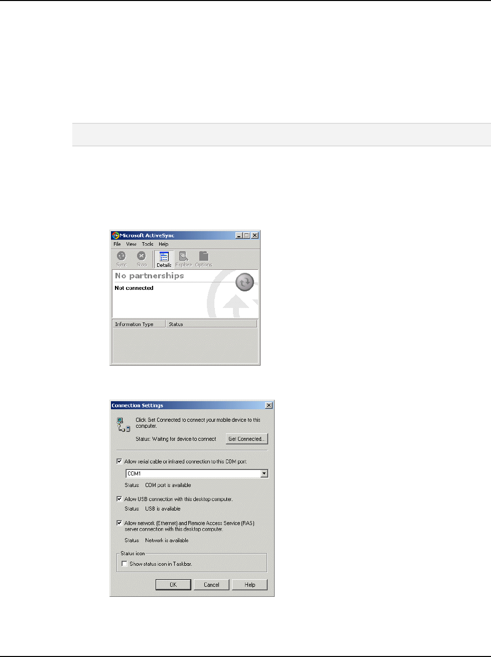
JETT•RFID+ Technical Reference Manual, MAN0352, Rev. A
4
-9
ActiveSync
ActiveSync is a desktop utility program (available as a free download from Microsoft) that allows you
to synchronize certain types of information between a PC and the JETT. You can also use ActiveSync to
transfer files and install programs on the JETT.
When connecting the JETT to the PC via ActiveSync, you can opt to create a partnership and
subsequently have the PC automatically recognize the JETT and synchronize information. You can also
create a temporary Guest partnership to copy files and install programs.
The following procedures describe how to make an ActiveSync connection using a serial interface cable.
For information on how to make an ActiveSync connection using Bluetooth or Wi-Fi, refer to the
appropriate manual.
Warning! Do not enable or utilize the RFID+ module with a cable connected. Operation of this nature is
likely to cause harmful interference.
Initial Communication
To setup initial communication between the PC and the JETT:
1. Connect an interface cable to an available COM port on the PC and the JETT’s RS-232 port.
2. On the PC, start ActiveSync.
3. On the ActiveSync menu bar, select Connection Settings from the File menu. The Connection
Settings dialog box opens.
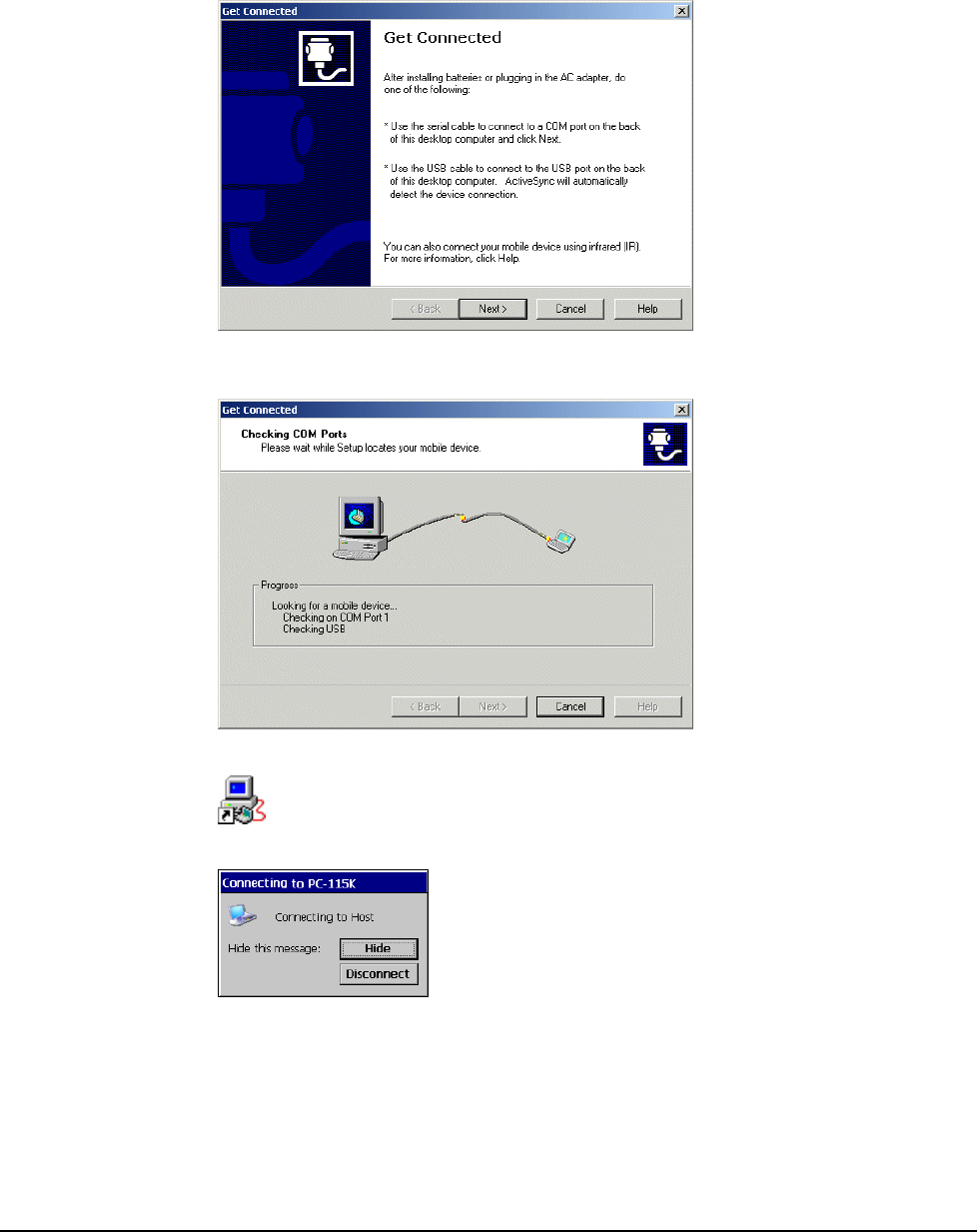
Configuration
4-10
4. If not selected, check the Allow serial cable or infrared connection to this COM port box, and
assign the number of the available COM port (typically COM1).
5. Click OK to exit.
6. On the ActiveSync menu bar, select Get Connected from the File menu. ActiveSync will then
start the Get Connected wizard.
7. Click Next. ActiveSync will start attempting to establish a connection (this process will take
several seconds).
8. On the JETT, tap PC Link.
The following message box appears:
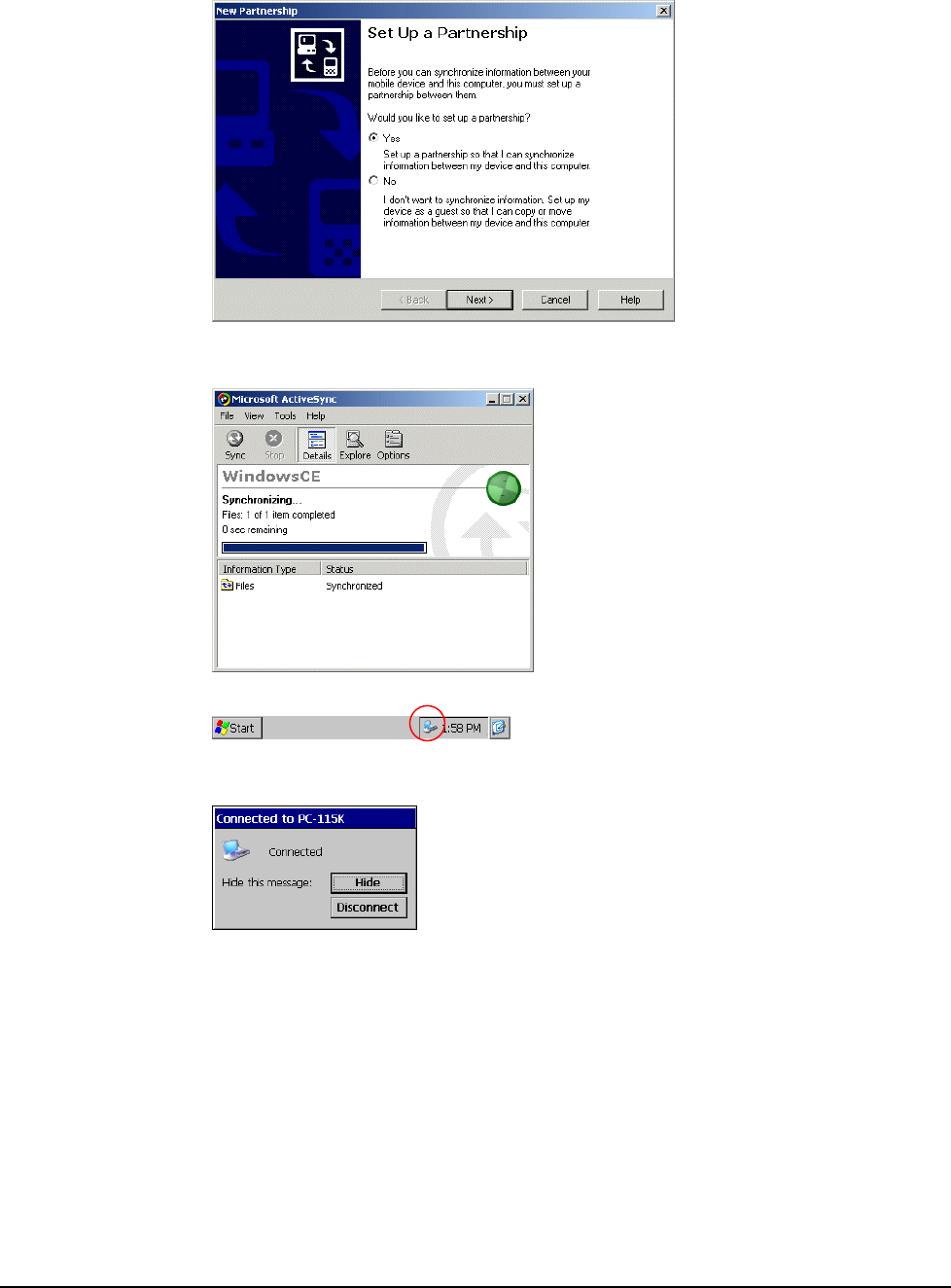
JETT•RFID+ Technical Reference Manual, MAN0352, Rev. A
4
-11
9. If ActiveSync successfully establishes communications, the ActiveSync dialog will briefly
reappear on the PC and start the New Partnership dialog wizard.
10. Select your Partnership option as needed and complete the wizard. The ActiveSync dialog box
will reappear and display a status of “Connected.” For example:
11. On the JETT, an icon indicating a ActiveSync connection will appear in the system tray.
12. To terminate the ActiveSync connection, double-tap the connection icon to display the Connect
to PC-115K dialog box and tap Disconnect.
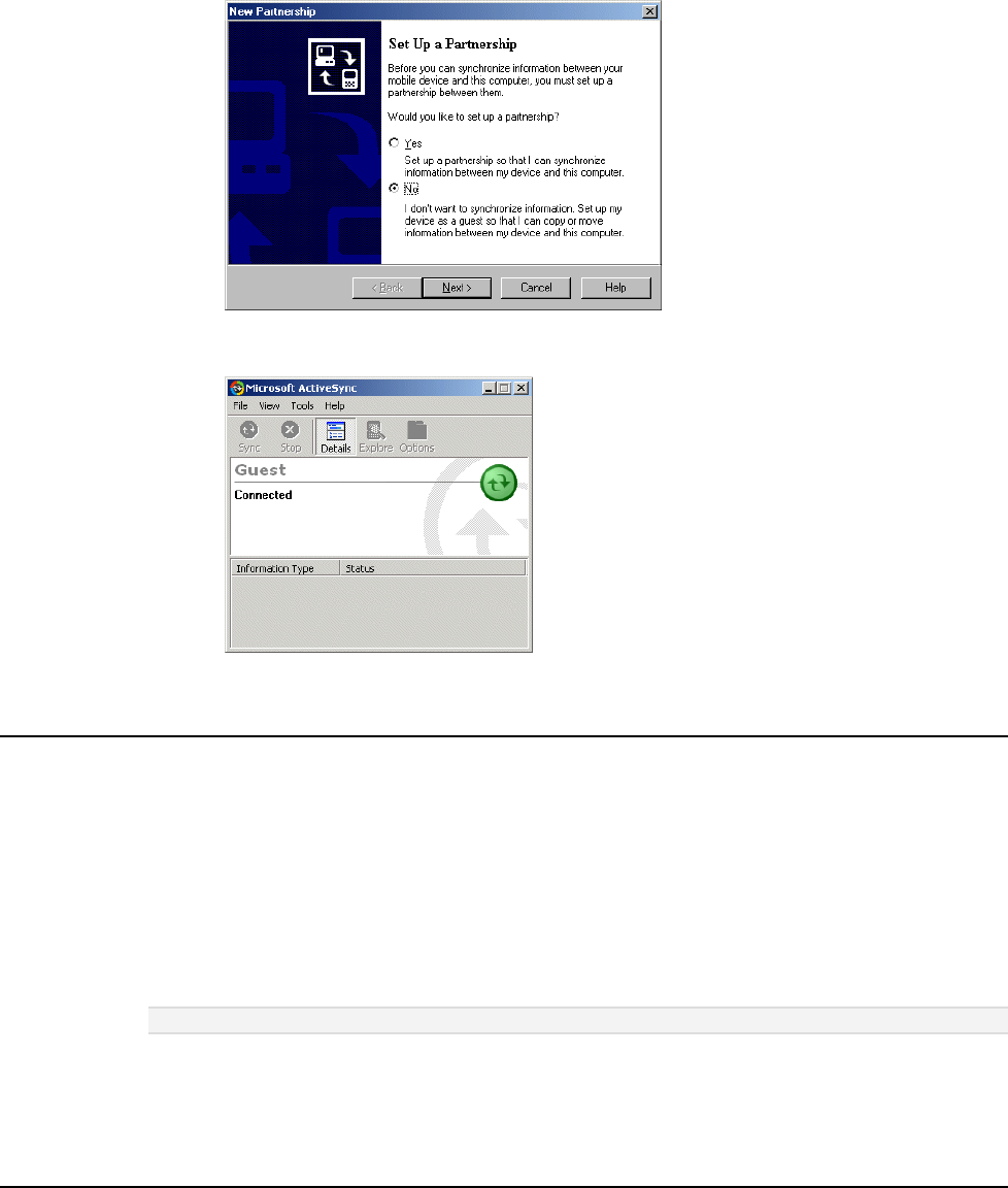
Configuration
4-12
Subsequent Communication
After you install ActiveSync and establish the initial communication between the PC and the JETT, use
the following procedure to set up subsequent sessions:
1. If not already attached, connect an interface cable to an available COM port on the PC and the
RS-232 port on the JETT.
2. On the JETT desktop, tap PC Link to attempt to reestablish communications
3. When communications is successfully reestablished, the New Partnership wizard appears.
4. Select No on the PC and then click Next. A status of “Connected” should appear in the
ActiveSync window.
Persistent Registry
Saving Changes to the Registry
The JETT internal memory consists of DRAM and Flash. Typically, any changes made to the JETT
including file creation are temporarily stored in the unit’s DRAM. You must then copy the files from
DRAM to internal flash memory or a removable compact flash card to store the information
permanently.
Consequently, if you do not store the information to flash memory and the unit loses power, all
information stored in DRAM will be lost. However, whenever you make changes that affect the
registry, such and changing settings in the Control Panel or installing software, you can permanently
store registry changes without writing to flash memory by using the Persistent Registry.
Note: The JETT will store registry information every time you perform a suspend operation.
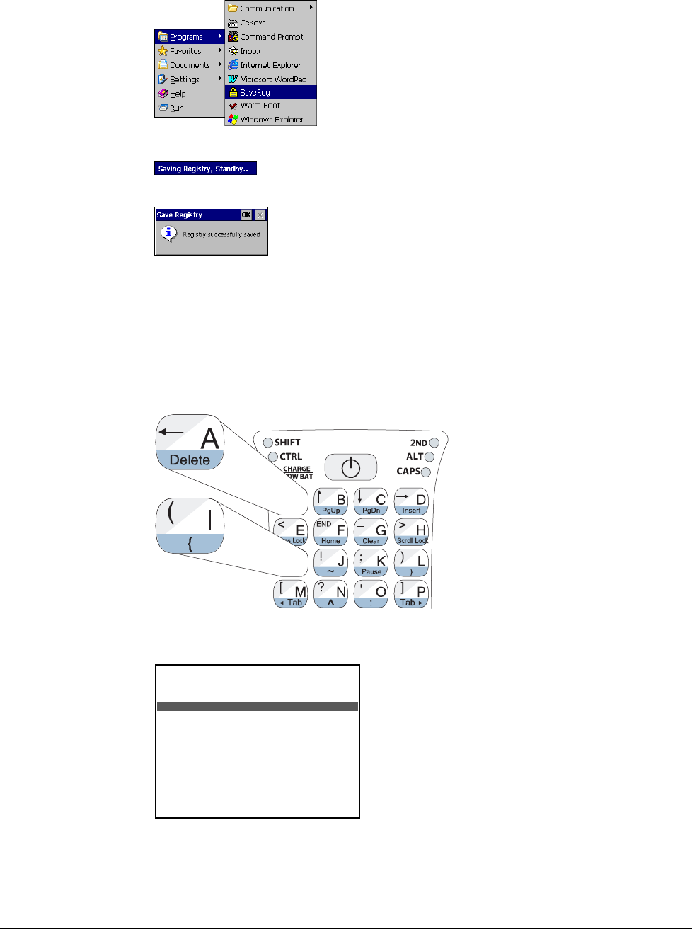
JETT•RFID+ Technical Reference Manual, MAN0352, Rev. A
4
-13
To store registry information on the JETT permanently:
1. From the Start menu, select Programs and tap SaveReg.
2. The JETT will begin saving the registry.
After you successfully save the registry, a message box will appear:
3. Tap OK to close the message box.
Resetting the Registry
To reset the Windows CE .NET registry back to the factory default settings:
1. Turn off the JETT.
2. While holding the key in Column 1, Row 1 (upper leftmost) and the key in Column 1, Row 3,
turn on the JETT. For example:
3. If you are successful, the screen will display version information, followed by “Invalidating
Persistent Registry,” before it completes the boot up process. For example:
Where x.x.x is the version number
***** JETT.ce *****
Loader Ver x.x.x
Booting nk.gz from System Socket
Reading gzip file from SYSTEM Socket
##########################################
Loading CE Image...
###

JETT•RFID+ Technical Reference Manual, MAN0352, Rev. A 5-1
Chapter 5: Application Development
Application Types
Before writing applications for Windows CE .NET 4.2 and the JETT, you will need to determine if your
applications will consist of managed code and/or native code.
• Managed code makes use of run-time environment application programming interfaces
(APIs), provides integrated security and memory management and is portable across software
platforms and processors. Code written in Microsoft Studio .NET 2003 is managed code.
• Native code uses a specific set of software platform APIs and microprocessor and as a result,
the compiled code will only run on that specific software platform and processor. Typically,
native code offers the highest performance with the smallest footprint, but it also requires
developers to write their own security and memory management code. Code written in
eMbedded Visual C++ 4.0 is native code.
The type of application being created will dictate the choice between native and Microsoft .NET—
connected code. When a consistent programming model and time-to-market are the primary
considerations, use Visual Studio .NET and the .NET Compact Framework. When performance, the
smallest working set, and low-level control are a top priority, use eMbedded Visual C++ 4.0.
Development Tools
To write Windows CE .NET 4.2 applications for the JETT, you will need to obtain one the following
Microsoft products:
• Visual Studio .NET 2003—this development tool installed with the .NET Compact
Framework allows you to build embedded managed applications for the JETT using C# and
Visual Basic.
Using Visual Studio .NET 2003 requires installation of the Windows CE Utilities for Visual
Studio .NET 2003, which is available as a free download from Microsoft.
• eMbedded Visual C++ 4.0—a standalone integrated development environment (IDE)
designed for developing native C++ applications for JETT.
Using eMbedded Visual C++ 4.0 requires installation of the Two Technologies’ JETT•ce SDK.
It includes APIs for application development, user interface design elements, and
documentation.
Other development tools you need include:
• ActiveSync—this Microsoft utility allow you to transfer files between the JETT and your
development system. It is are available as a free download from Microsoft.
• Kbtool.exe—included with the JETT•ce SDK, this MS-DOS application enables you to remap
the JETT keyboard.
Note: After installing any Microsoft product from a disk, you should check their website for newer versions or
service packs.

Application Development
5-2
Using Visual Studio .NET
Visual Studio .NET 2003 provides a robust development environment for creating applications that
target the .NET Compact Framework. Included with Visual Studio .NET is a set of pre-built device
profiles. A device profile contains information necessary to build applications that target specific
devices, such as the JETT.
System Requirements
To use Visual Studio .NET 2003, your development system must meet the following minimum
requirements:
Processor 450 MHz Pentium II,
Operating Systems Windows Server 2003, Windows 2000 Server or Professional (SP3 or later) or
Windows XP Professional or Home Edition¹
RAM Memory Windows Server 2003 & Windows XP Professional : 160 MB
Windows 2000 Professional & Windows XP Home Edition: 96 MB of RAM
Windows 2000 Server: 192 MB of RAM
Disk Space System Drive: 900 MB, Installation Drive: 3.3 GB
Optional MSDN Library documentation: 1.9 GB
Drive CD-ROM or DVD-ROM drive
Display Super VGA (1024 x 768) or higher-resolution display with 256 colors
Mouse Mouse or compatible pointing device
1. Visual Studio .NET 2003 does not support creating ASP.NET Web applications or ASP.NET XML Web services when using
Windows XP Home Edition.
The .NET Compact Framework
The .NET Compact Framework is a subset of the .NET Framework designed specifically for small,
resource-constrained devices, such as the JETT. Applications that run on top of the .NET Compact
Framework are able to use a range of run-time services—including a common language run-time,
memory management, and a rich set of base classes that handle security, data access, and XML Web
services.
Supported Languages
The .NET Compact Framework currently supports two development languages, C# .NET and Visual
Basic .NET.
You should also be aware that there is another language limitation under the .NET Compact
Framework. Under the .NET Framework, you can use mixed-language components within a single
project. In comparison, .NET Compact Framework projects are restricted to a single language, either C#
.NET or Visual Basic .NET. The workaround to this single-language project limitation imposed by .NET
Compact Framework is to create additional projects using the Class template. Add your alternate
language code to the template, and then simply add references to these classes in your application
project.

JETT•RFID+ Technical Reference Manual, MAN0352, Rev. A
5
-3
.NET Compact Framework Limitations
You use the same Visual Studio .NET environment that you use when developing desktop applications,
but in order to fit the .NET Framework into the operating constraints of Windows CE, the following
limitations apply:
• Method Overloads—overloading a method provides alternative ways to call that method, but
it also increases the size of the Framework. As a result, the .NET Compact Framework
trimmed the overloads from almost all methods. Consequently, there is a good chance that a
particular method overload you used with a desktop application will not be available when
developing .NET Compact Framework-based applications.
• Missing Controls—a number of .NET Framework controls are not part of the .NET Compact
Framework. The absence of most of these controls (such as printing) is insignificant to mobile
developers. You can replace many of the missing dialogs with your own dialogs or by
accessing system dialogs directly using the Windows CE API.
• XML Functionality—as much as the .NET Compact Framework offers in the way of XML, an
equal amount of functionality was trimmed. A key missing XML-related component is the
System.Xml.XPath namespace. In its absence, you can use a combination of recursive and
iterative searches against the Document Object Model (DOM). Another missing key XML
component is Extensible Style sheet Language Transformation (XSLT), which convert an XML
document into different formats. In addition, the .NET Compact Framework does not
currently provide support for developing device-based XML Web services.
• Database Support—the .NET Compact Framework offers a robust set of data-related tools.
SQL Server CE provides local database support, while on the server side, the .NET Compact
Framework provides support for SQL Server.
• Binary Serialization—due to size and performance considerations both the BinaryFormatter
and SoapFormatter classes are not part from the .NET Compact Framework.
• Access to the Windows Registry—the .NET Framework uses the Microsoft.Win32.Registry
namespace to work with the Windows registry from an application. Because it relates to Win32
and not Windows CE, this namespace was not included in the .NET Compact Framework.
However, you can access the Windows CE registry by invoking the relevant Windows APIs.
• Leveraging COM Components—incorporating COM objects into a .NET Compact
Framework-based application is a two-step process. First, you must write an unmanaged DLL
wrapper using eMbedded Visual C++ that exposes the COM object. Then, you must use
PInvoke to access your DLL wrapper.
• Security—the .NET Compact Framework does not secure access to unmanaged code. Any
application can call any system or non-system API. There is currently no role-based security
with the .NET Compact Framework. The principal object has no understanding of known
identity or known role.
• XML Web Services—the most notable exclusion from the .NET Compact Framework XML
Web service capabilities is the ability to use cookies. Cookies are widely used to maintain state
on the server between calls from a client. While the use of cookies in Web services is not as
prevalent as their use on Web sites, they are still in use. The .NET Compact Framework offers
limited cryptographic abilities with respect to Web services.
• Printing—the .NET Compact Framework provides no support for printing. There is no easy
way to interact with network printers. The workaround for accessing network printers is to
build a server-based application, which accepts and prints jobs submitted by your application.
• GDI+—Windows CE .NET does not natively support GDI+, and therefore is not part of the
.NET Compact Framework.
• Remoting—the initial release of the .NET Compact Framework does not support remoting. If
you need to communicate with .NET components situated on a remote machine, you should
implement an XML Wed service façade for the component and access it that way.
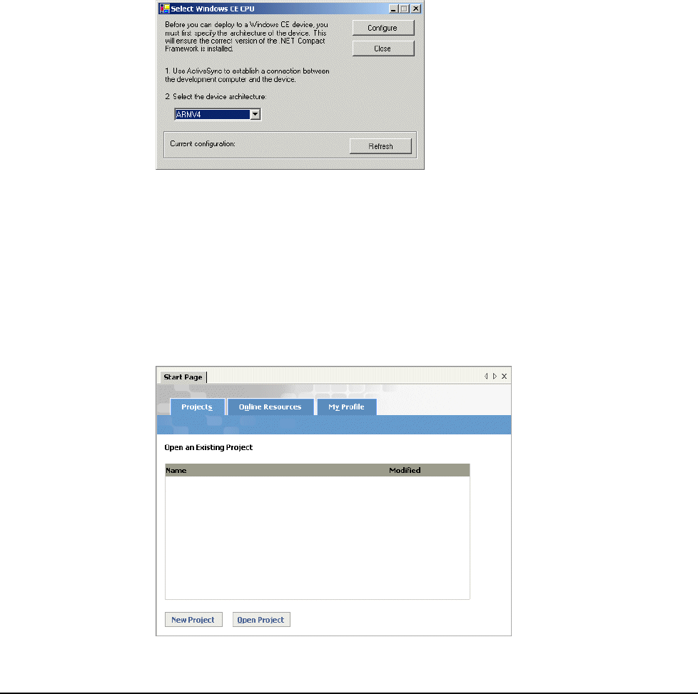
Application Development
5-4
Getting Started with Visual Studio .NET
The section will help you become familiar JETT application development using Visual Studio .NET
2003. Procedures in this section include creating a “Hello World” application, deploying the application
and creating a redistributable CAB file. For more information about using Visual Studio .NET, refer to
its online help.
Preliminary Setup
Before using Visual Studio .NET 2003 to create a “Hello World” project for the JETT, you must assign a
device CPU.
To assign a device CPU:
1. Using ActiveSync, establish communication with the JETT.
2. Start Visual Studio .NET 2003.
3. On the Tools menu, click Select Windows CE Device CPU. The Select Windows CE Device
CPU dialog box opens.
4. Select ARMV4 as the device architecture from the drop-down box and click Configure.
5. Click Close and exit Visual Studio .NET.
Creating a “Hello World” Application
After restarting Visual Studio .NET, you will be able to create, debug and deploy managed code
applications for the JETT.
To create a “Hello World” project in Visual Basic .NET:
1. Restart Visual Studio .NET 2003.
2. From the File menu, select New, and then click Project.
3. Click New Project. The New Project Dialog box opens.
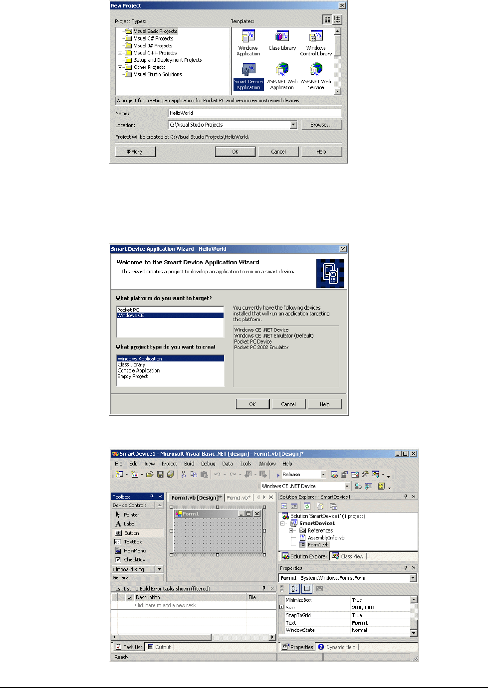
JETT•RFID+ Technical Reference Manual, MAN0352, Rev. A
5
-5
4. Under Project Types, select Visual Basic Projects.
5. Under Templates, select Smart Device Application.
6. Type the Name (such as HelloWorld) and then select the Location of the project (such as
C:\Visual Studio Projects).
7. Click OK. The Smart Device Application Wizard opens.
8. Select Windows CE as the target platform, Windows Application as the project type and then
click OK. You are now ready to begin application development.
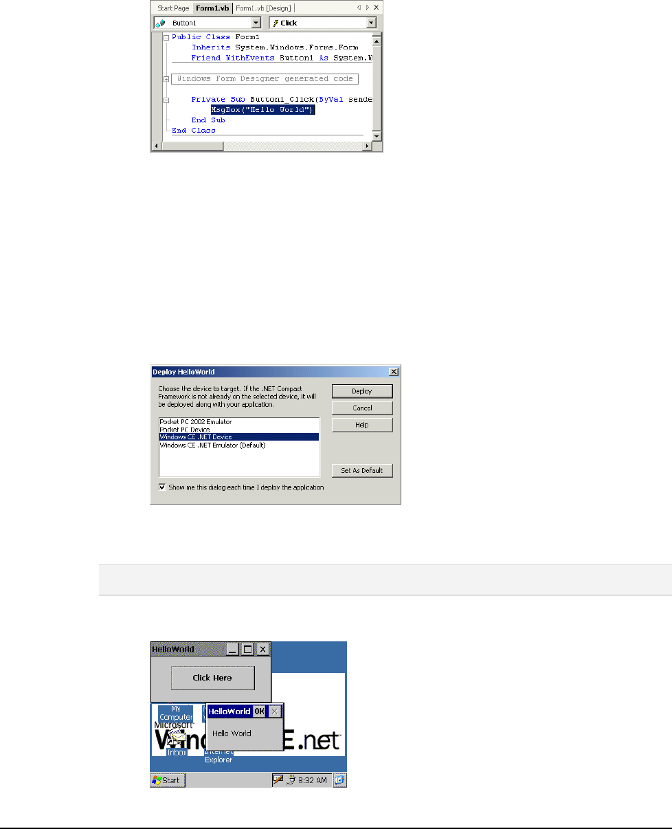
Application Development
5-6
9. To ensure that the form fits on the JETT, change the Size in the Form1 properties to 200,100.
Also, change the Text to “Hello World.”
10. Using the Toolbox (selected from the View menu), place a button on the form and then double-
click the button to open the code window.
11. Enter the following line of code in the button's Click event handler:
MsgBox("Hello World")
Building and Deploying the Application
Before building your application, you must select a configuration type (Debug or Release). A Debug
configuration will compile with full symbolic debug information, but no optimization. A Release
configuration with compile with full optimization, but contain no symbolic debug information.
To build and deploy the application to the JETT:
1. On the Standard toolbar, choose Release from the Solution Configurations list box.
2. From the Build menu, select Build HelloWorld. Visual Studio .NET will then build the
HelloWorld application. Review the Output panel to make sure the build succeeded without
any errors. You are now ready for deployment.
3. From the Build menu, select Deploy HelloWorld. The HelloWorld dialog box opens.
4. Choose Windows CE .NET Device as the target smart device and click Deploy to start the
deployment process. Visual Studio .NET will then communicate with the JETT, create a
HelloWorld folder under "\Program Files" and install the HelloWorld application there.
Note: To store the files permanently, you can either copy the files to internal compact flash (the SystemCF
folder) to a memory card.
5. To run the HelloWorld application on the JETT, select Programs from the Start menu and tap
HelloWorld, then click the button on the form to display “Hello Word.”
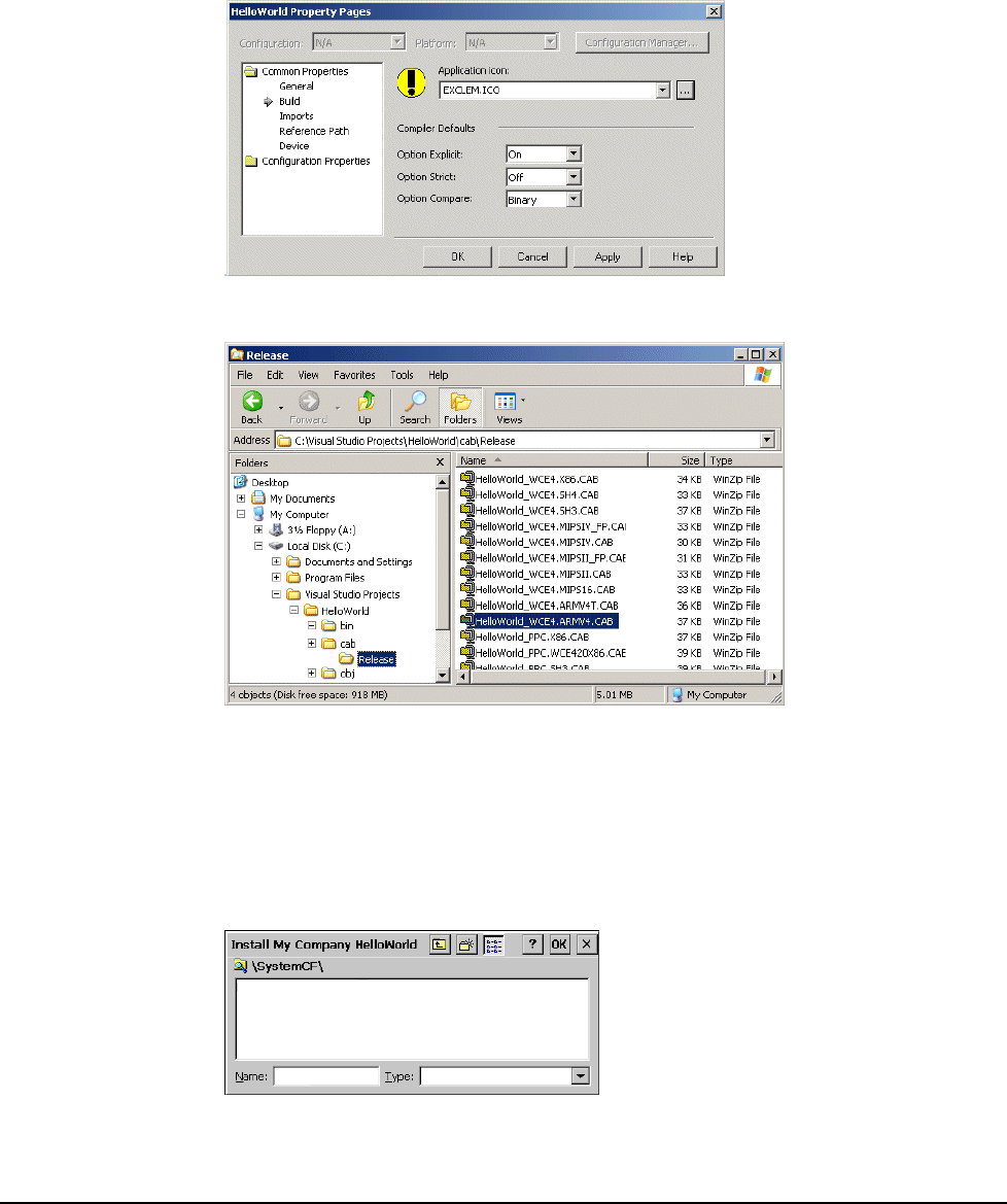
JETT•RFID+ Technical Reference Manual, MAN0352, Rev. A
5
-7
Creating a Redistributable CAB File
To create a redistributable CAB file for the JETT:
1. From the Project menu, select Properties. In the Common Properties node, select Build.
2. Use the Browse button to locate an icon (.ICO file). By default, icon files are installed in the
"C:\Program Files\Microsoft Visual Studio.NET 2003\Common7\ Graphics\icons" folder.
In this example, choose exclem.ico from the "Misc" subdirectory and click OK. Visual Studio
.NET will then add the icon to the project files and set the icon file's Build Action to Content.
3. From the Build menu, choose Build Cab File. This action creates CAB files in your project’s
“\cab\Release” folder for all supported hardware platforms.
4. Using ActiveSync, copy the HelloWorld_WCE4.ARMV4.CAB to the Temp folder on the JETT.
Refer to the “Using ActiveSync” section for details.
5. After you transfer the CAB file, simply tap it to perform the installation.
By default, the CAB file installation program will automatically attempt to install the
HelloWorld application and related files in a folder under "\Program Files," but this action
will only store the files temporarily in the unit’s DRAM (i.e., if you turn the power off, the
application files will be lost). To store the files permanently, you can either copy the files to
internal compact flash (the SystemCF folder) to a memory card.
6. To run the HelloWorld application on the JETT, select Programs from the Start menu and tap
HelloWorld.

Application Development
5-8
Using eMbedded Visual C++ 4.0
eMbedded Visual C++ 4.0 is a standalone integrated development environment (IDE) designed for
developing applications for JETT. It consists of an integrated set of windows, tools, menus, toolbars,
directories, and other elements to help create, test, and debug a Windows CE application.
As of this writing, eMbedded Visual C++4.0, this program and its subsequent service patches are
available for download on Microsoft’s website.
Migrating Previous Versions of eMbedded Visual Tools
Windows CE .NET 4.2 does not support the use of eMbedded Visual Tools 3.0.
If you want to continue developing applications in Visual Basic, you will be able to use Visual Studio
.NET, but you will not be able to directly migrate your existing applications to Visual Basic .NET.
However, Visual Basic .NET does includes an Upgrade Wizard for migrating Visual Basic 6.0
application and some portion of your eMbedded Visual Basic applications will be able to take
advantage of this feature. You can find additional information on the MSDN Web site.
Developers using eMbedded Visual C++ 3.0 can rebuild their application in eMbedded Visual C++ 4.0.
System Requirements
To use eMbedded Visual C++ 4.0, your development system must meet the following minimum
requirements:
Processor 450 MHz Pentium II
Operating Systems Windows 2000 Server
Windows 2000 Professional (SP2 or later)
Windows XP Professional
Memory Windows 2000 Professional & Windows XP Professional: 96 MB RAM
Windows 2000 Server: 192 MB RAM
Disk Space 200 MB
Drive CD-ROM
Display VGA or higher-resolution monitor
Mouse Mouse or compatible pointing device
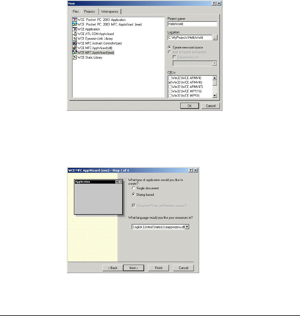
JETT•RFID+ Technical Reference Manual, MAN0352, Rev. A
5
-9
Getting Started with eMbedded Visual C++ 4.0
The section will help you become familiar with JETT application development using eMbedded Visual
C++ 4.0. Procedures in this section include creating a “Hello World” application, deploying the
application and creating a redistributable CAB file. For more information about using eMbedded Visual
C++ 4.0, refer to its online help.
Creating a “Hello World” Application
To create a “Hello World” project:
1. Using ActiveSync, establish communication with the JETT.
2. Start eMbedded Visual C++ 4.0.
3. From the File menu, select New. The New dialog box opens.
4. In the New dialog box :
Type in the Project Name and select a location.
Under Projects, select WCE MFC AppWizard (exe).
Under CPUs, check Win32 (WCE ARMV4I).
5. Click OK. The WCE MFC AppWizard (exe) dialog box opens.
6. Click Dialog based and then click Finish. The New Project information dialog box opens.
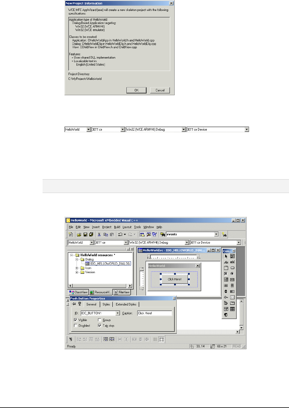
Application Development
5-10
7. Click OK to close. The HelloWorld workspace opens in the upper left pane.
8. On the WCE Configuration toolbar, select JETT ce for the Active WCE Configuration, Win32
(WCE ARMV4I) Debug for the Active Configuration and JETT ce Device as the device type.
9. Add a button to the form:
In the HelloWorld workspace, click the Resources tab, expand the Dialog folder and then
double-click IDD_HELLWORLD_DIALOG. The HelloWorld form opens in the adjoining
pane.
From the Controls toolbar, drag a button onto the form.
Note: If the Controls toolbar does not appear, you can activate it by right clicking the WCE Configuration
toolbar
Right-click the button, select Properties. The Push Button Properties dialog box opens.
Change the caption to "Click Here!" and close the dialog box.
10. Double-click the button. The Add Member Function dialog box opens.
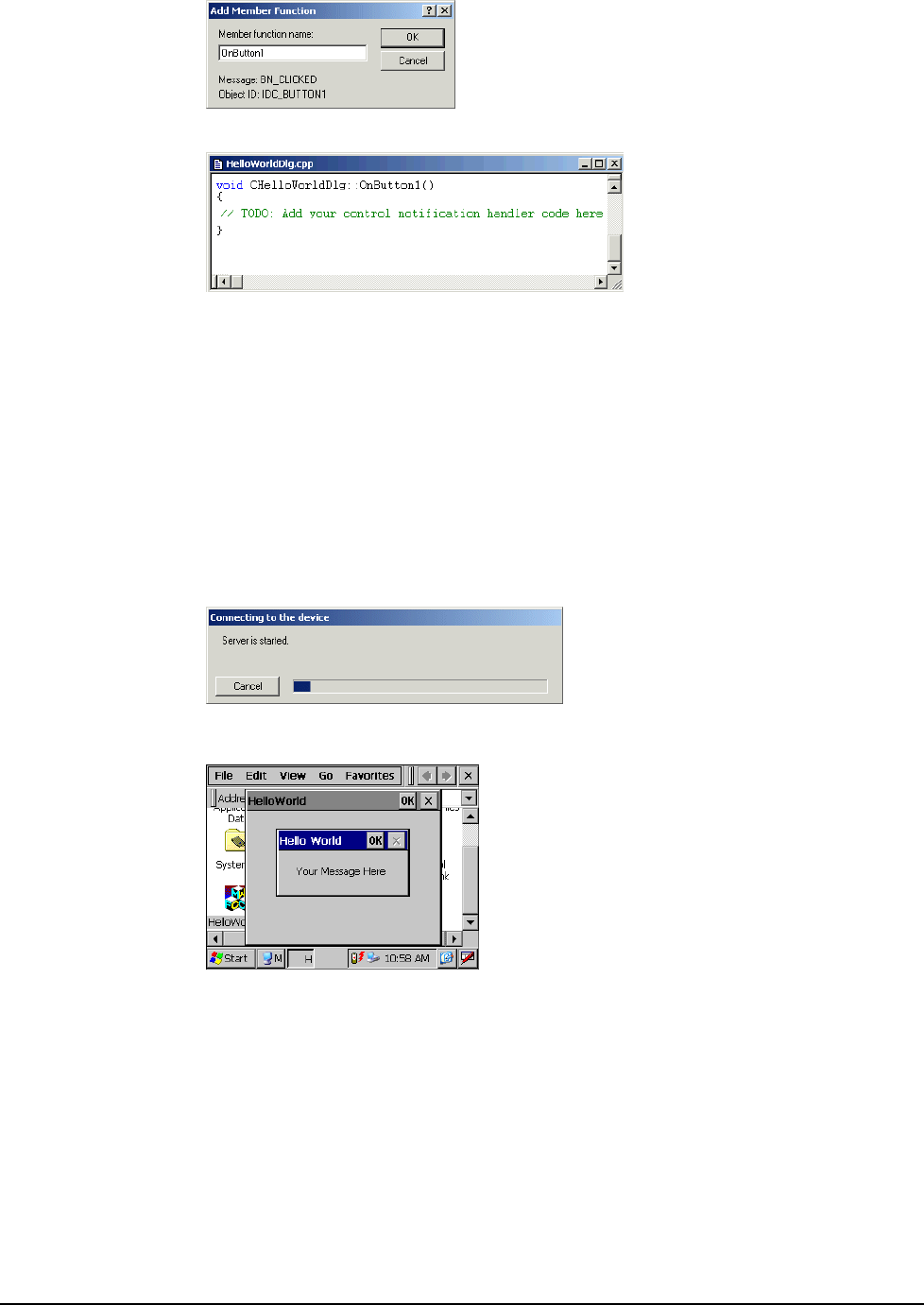
JETT•RFID+ Technical Reference Manual, MAN0352, Rev. A
5
-11
11. Click OK to add the member function. HelloWorldDlg.cpp opens in a new window.
12. Replace the text:
// TODO: Add your control notification handler code here
with the text:
MessageBox (TEXT (" Your Message Here "), TEXT("Hello World"), MB_OK);
Building and Deploying the Application
To build and deploy the application to the JETT:
1. From the Build Menu, select Build HelloWorld.exe.
2. eMbedded Visual C++ 4.0 will then compile the program and attempt communication via
ActiveSync with the JETT to download the application. After the transfer completes, you can
then run the application on the JETT.
3. On the JETT, navigate to the My Computer folder and double-tap the HelloWorld icon to run
the application.
4. Tap Click Here on the form to display “Hello Word.” Tap OK to close
Storing the Application File
When eMbedded Visual C++ 4.0 deploys the HelloWorld application to the JETT, it also copies the
Mfcce400d.dll file to the \Windows folder. Both files are temporarily stored in the unit’s DRAM.
As long as the JETT remains powered on, you will be able to execute the HelloWorld application. If you
turn the power off, the application files will be lost.
To store the files permanently, you can either copy the files to internal compact flash (i.e., the SystemCF
folder) or to a memory card.
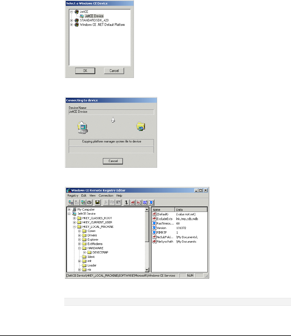
Application Development
5-12
Using the Remote Registry Editor
By installing Microsoft eMbedded C++ 4.0, you can view or edit the Windows CE .NET Registry on the
JETT. If you make any changes, you must invoke the Save Registry command to store the changes on
the JETT.
To use the Windows CE .NET Remote Registry Editor:
1. If needed, establish an ActiveSync connection.
2. From the Tools menu in eMbedded C++ 4.0, select Remote Tools and choose Registry Editor.
The Select a Windows CE Device dialog box opens.
3. Under JettCE, select JettCE Device and click OK. eMbedded C++ 4.0 will then attempt to copy
the necessary files to the JETT to view the registry.
4. After the file transfer successfully completes, the JETT registry should appear in Windows CE
.NET Remote Registry Editor.
5. To change a registry value, double-click the value that you want to change. To add or delete a
registry value, use the Edit menu.
Warning! Changing the registry values on the JETT can adversely effect its performance.
6. After making your changes, perform a Save Registry on the JETT.

JETT•RFID+ Technical Reference Manual, MAN0352, Rev. A
5
-13
Incorporating JETTce.dll Functionality
JETTce.dll provides developers a method to quickly incorporate some or all of the following functions
into their eMbedded C++ 4.0, Visual Basic .NET 2003 and Visual C# .NET 2003 application:
• Screen Brightness—the following API calls enable you to increase or decrease the screen
brightness in 20 percent increments:
IncBrightness
DecBrightness
• Enable/Disable/Test Auxiliary Power—on units with a COM port that supplies power, the
following API calls enable you to turn on, turn off and test the power for connected devices
(such as RFID modules and bar code readers):
TurnAuxSwitchOff
TurnAuxSwitchOn
AuxSwitchIsOn
• Soft Keyboard—the following API calls enable you to launch, display, hide, center and close
the CeKeys program, a data entry program that replaces Microsoft’s’ Soft Input Panel (SIP) in
OS versions 4.20.44 and above:
IsCeKeysRunning
IsCeKeysDisplayed
RunCeKeys
DisplayCeKeys
HideCeKeys
CenterCeKeys
ShutDownCeKeys
• Enable/Disable LEDs—the following API calls enable you to turn on and turn off the
JETT•ce’s LEDs:
LedUpdate
• Return MAC Address—the following API calls enable you to return the JETT•ce’s unique
MAC Address:
GetMacAddress
• Suspend Function Control—the following API calls allow you to enable/disable the suspend
function on the ON/OFF switch, and also return its status:
Suspend_Key_Lockout_Off
Suspend_Key_Lockout_On
Suspend_Key_Lockout
Suspend_Key_Lockout_State
• Beep Driver Control—the following API calls enable you to control the frequency, volume
and duration (in milliseconds) of the beep driver:
PlayTone
• Suspend Device—the following API calls enable you to suspend the JETT:
SuspendDevice
• Keypad Backlight Control—for JETTs with LED backlight keypads, the following API calls
enable you to turn off or on the keypad backlight:
RunwayLEDs
• Display Version Number—the following API calls enable you to return the OS image version:
GetNkBinVersion

Application Development
5-14
IncBrightness
This function enables you to increase the screen brightness in 20 percent increments.
Syntax
void IncBrightness(
void
);
Parameters
None
Return Values
None
DecBrightness
This function enables you to decrease the screen brightness in 20 percent increments.
Syntax
void DecBrightness(
void
);
Parameters
None
Return Values
None
TurnAuxSwitchOn
On units with a COM port that supplies power, this function turns on the power for connected devices,
such as RFID modules and bar code readers.
Syntax
void TurnAuxSwitchOn(
void
);
Parameters
None
Return Values
None
TurnAuxSwitchOff
On units with a COM port that supplies power, this function turns off the power for connected devices,
such as RFID modules and bar code readers.
Syntax
void TurnAuxSwitchOff(
void
);
Parameters
None
Return Values
None

JETT•RFID+ Technical Reference Manual, MAN0352, Rev. A
5
-15
AuxSwitchIsOn
On units with a COM port that supplies power, this function returns the status off the power for
connected devices, such as RFID modules and bar code readers.
Syntax
bool AuxSwitchIsOn(
void
);
Parameters
None
Return Values
Values Description
TRUE Indicates auxiliary power is on.
FALSE Indicates auxiliary power is off.
IsCeKeysRunning
This function returns the status of the CeKeys data entry program.
Syntax
bool IsCeKeysRunning(
void
);
Parameters
None
Return Values
Values Description
TRUE Indicates that CeKeys is active.
FALSE Indicates that CeKeys is inactive.
IsCeKeysDisplayed
This function returns the display status of the CeKeys data entry program.
Syntax
bool IsCeKeysDisplayed(
void
);
Parameters
None
Return Values
Values Description
TRUE Indicates that CeKeys is running on the desktop.
FALSE Indicates that CeKeys is minimized in the system tray or inactive.

Application Development
5-16
RunCeKeys
This function invokes the CeKeys data entry program.
Syntax
bool RunCeKeys(
void
);
Parameters
None
Return Values
Values Description
TRUE Indicates that CeKeys successfully executed.
FALSE Indicates that CeKeys failed to execute.
DisplayCeKeys
This function displays the CeKeys data entry program (if running) on the desktop.
Syntax
bool DisplayCeKeys(
void
);
Parameters
None
Return Values
Values Description
TRUE Displays CeKeys (if running) on the desktop.
FALSE Indicates that it could not display CeKeys.
HideCeKeys
This function minimizes the CeKeys data entry program (if running) in the system tray.
Syntax
bool HideCeKeys(
void
);
Parameters
None
Return Values
Values Description
TRUE Minimizes CeKeys (if running) in the system tray.
FALSE Indicates that it could not hide CeKeys.

JETT•RFID+ Technical Reference Manual, MAN0352, Rev. A
5
-17
CenterCeKeys
This function places the CeKeys data entry program (if running) in the center of the desktop.
Syntax
bool CenterCeKeys(
void
);
Parameters
None
Return Values
Values Description
TRUE Places CeKeys (if running) in the center of the desktop.
FALSE Indicates that it could not center CeKeys.
ShutDownCeKeys
This function terminates the CeKeys data entry program.
Syntax
bool ShutDownCeKeys (
void
);
Parameters
None
Return Values
Values Description
TRUE Indicates that it successfully closed CeKeys (if running).
FALSE Indicates that it could not close CeKeys.

Application Development
5-18
LedUpdate
This function enables you to turn on and turn off the LEDs on the JETT.
Syntax
bool LedUpdate(
LEDVALUE ledVal,
bool bValue
);
Parameters
Values Description
ledVal [In] Specifies of the following LEDs:
LED_2ND
LED_SHIFT
LED_CTRL
LED_ALT
LED_CAPS
bValue [In] TRUE turns on specified LED. FALSE turns off specified LED.
Return Values
Values Description
TRUE Indicates success.
FALSE Indicates failure.
GetMacAddress
This function returns the MAC address of the JETT, where the high order of the MAC address
(pHighMac) returns a two-character value (always 48) and the low order of the MAC address
(pLowMac) a unique ten-character value. For example:
High Value: 48
Low Value: 3472888915
You can use the pLowMac value to uniquely identify each JETT. This number can be helpful in an
environment (such as Bluetooth) where multiple units can report to a single host device.
Syntax
bool GetMacAddress(
PDWORD pHighMac,
PDWORD pLowMac
);
Parameters
Values Description
pHighMac [Out] Specifies a two-character value (always 48).
pLowMac [Out] Specifies a unique ten-character value.
Return Values
Values Description
TRUE Indicates success.
FALSE Indicates failure.

JETT•RFID+ Technical Reference Manual, MAN0352, Rev. A
5
-19
Suspend_Key_Lockout_Off
This function enables the suspend/resume function.
Syntax
bool Suspend_Key_Lockout_Off(
void
);
Parameters
None
Return Values
Values Description
TRUE Indicates that you can suspend the unit.
FALSE Indicates that the function failed.
Suspend_Key_Lockout_On
This function disables the suspend/resume function.
Syntax
bool Suspend_Key_Lockout_On(
void
);
Parameters
None
Return Values
Values Description
TRUE Indicates that you cannot suspend the unit.
FALSE Indicates that the function failed.
Suspend_Key_Lockout_State
This function returns the status of the current suspend/resume lockout state
Syntax
bool Suspend_Key_Lockout_State(
PDWORD pdwLockoutState
);
Parameters
Values Description
pdwLockoutState [Out] Returns the status of the suspend lockout state, where 1 = TRUE and 0 =
FALSE.
Return Values
Values Description
TRUE Indicates success.
FALSE Indicates failure.

Application Development
5-20
Suspend_Key_Lockout
This function allows you enable, disable and return the status of the suspend/resume function on the
On/Off switch
Syntax
bool Suspend_Key_Lockout(
PBOOL pbLockoutState
);
Parameters
Values Description
pbLockoutState Specifies one of the following:
[In] LOCKOUT_OFF
[In] LOCKOUT_ON
[Out] LOCKOUT_READ
Return Values
Values Description
TRUE Indicates success.
FALSE Indicates failure.
PlayTone
This function enables you to access the beep driver for various purposes, such as notifying an operator
that a malfunction occurred or that a process has finished. Parameters that you can define include
frequency, volume and duration (in milliseconds).
Syntax
bool PlayTone(
int iFrequency,
int iVolume,
int iDurationMS
);
Parameters
Values Description
iFrequency Specifies the beep frequency. Range: 56 to 20000 KHz.
iVolume Specifies the beep volume. Range: 1 to 100.
iDurationMS Specifies the beep duration in milliseconds Range 1 to 10000 (10 seconds).
Return Values
Values Description
TRUE Indicates success.
FALSE Indicates failure.

JETT•RFID+ Technical Reference Manual, MAN0352, Rev. A
5
-21
SuspendDevice
This function enables you to suspend the JETT
Syntax
void SuspendDevice(
void
);
Parameters
None
Return Values
None
RunwayLEDs
For JETTs with LED backlight keypads, this function enables you to turn off or on the keypad backlight
Syntax
DWORD RunwayLEDs(
DWORD dwFunction
);
Parameters
Arguments Values
DWORD dwFunction To turn the LED backlight for the keypad off, set the value to 0
To turn the LED backlight for the keypad on, set the value to1
Any other value will just return the status
Return Values
Values Description
0 Indicates that the LED backlight for the keypad is off
1 Indicates that the LED backlight for the keypad on

Application Development
5-22
GetNkBinVersion
This function returns a 32-bit value that contains the OS version number and the build image version
number.
Syntax
dword GetNkBinVersion(
void
);
Parameters
None
Return Values
Values Description
MSB Most Significant Byte = Windows CE .NET major version number
NSB Next Most Significant Byte = Windows CE .NET minor version number
LSS Least significant Short (two bytes) = build image (NK.BIN/NK.GZ) version
number
For example a return hex value of 04 02 0054 would indicate the following:
• Windows CE .NET Major Version = 4
• Windows CE .NET Minor Version = 4
• Build Image (NK.BIN/NK.GZ) Version = 84
You can also use a byte packed structure to access each of the fields, for example:
#include <pshpack1.h> // pack on byte boundaries
typedef struct
{ USHORT usNkBinVersion; // 16 bit field for the individual build number
UCHAR ucCeMinorVersion; // 8 bit field for the CE minor version
UCHAR ucCeMajorVersion; // 8 bit field for the CE major version
} VERSION_INFO, *PVERSION_INFO;
#include <poppack.h> // restore packing

JETT•RFID+ Technical Reference Manual, MAN0352, Rev. A
5
-23
Incorporating JETTRFIDp.dll Functionality
JETTRFIDp.dll provides developers in eMbedded C++ 4.0, Visual Basic .NET 2003 and Visual C# .NET
2003 a method to quickly incorporate RFID functionality (initialization, configuration, read and write
data, etc.) for JETT•RFID+ applications.
Use the following API calls contained within the JETTRFIDp.dll for all tag types supported by the
JETT•RFID+ modules:
• InitRFID
• GetFirmwareVersion
• SetReader
• SleepMode
• WakeMode
• ReadTagID
• CloseRFID
• GetTagInfo
• ReadTagData
• ReadTagDataB
• ClearDataBlocks
• LockDataBlocks
• WriteTagData
• WriteTagDataB
Use the following API calls contained within the JETTRFIDp.dll for just the MIFARE tag types
supported by the JETT•RFID+ modules:
• AuthorizeTag
• AuthorizeTagB
• WriteKey
• WriteKeyB

Application Development
5-24
InitRFID
This function enables the RFID+ module. When you call this function, it opens the COM2 port on the
JETT•RFID+ at 57600 kbs and turns on the auxiliary power
Syntax
bool InitRFID(
int iErrorCode
);
Parameters
Values Description
iErrorCode [Out] Pointer to the error code if this function fails.
Return Values
Values Description
TRUE Indicates success.
FALSE Indicates otherwise (error code returned though pointer).
GetFirmwareVersion
This function reads the firmware version from the RFID+ module. You can call this function anytime
after you initialize the RFID+ module with the InitRFID function.
Syntax
bool GetFirmwareVersion (
BSTR bsVersion,
int iBytes
int iErrorCode
);
Parameters
Values Description
bsVersion [Out] Buffer that contains data read from the RFID+ module.
iBytes [In] Number of data bytes in the bsVersion buffer.
iErrorCode [Out] Pointer to the error code if this function fails.
Return Values
Values Description
TRUE Indicates success.
FALSE Indicates otherwise (error code returned though pointer).

JETT•RFID+ Technical Reference Manual, MAN0352, Rev. A
5
-25
SetReader
This function sets up the RFID+ module to read tag IDs (use the ReadTagID function to read the tags).
Note: When using loop mode, you can continuously call the ReadTagID function to find tag IDs. In
addition, you will only need to call this function once until you send another command to the RFID module.
Syntax
bool SetReader (
RFID_FLAG rfFlag,
RFID_TAGTYPE rtTagType,
int iErrorCode
);
Parameters
Values Description
rfFlag [In] Flag sent to the reader to indicate one of the following read modes:
FLAG_00_SELECT_TAG—the RFID+ module will just read the first tag
encountered within its range.
FLAG_01_SELECT_TAG_LOOP—the RFID+ module will continuously
read tags within its range (even the same tag several times) until you
send it another command.
FLAG_02_ANTI_COLLISION—the RFID+ module will read all
ISO15693 tags encountered within its range once, storing each tag ID
FLAG_03_ANTI_COLLISION_LOOP— the RFID+ module will read all
ISO15693 tags encountered within its range once, storing each tag ID but
continue to scan for additional tags until you send it another command.
rtTagType [In] Specifies one of the following tag types:
TAGTYPE_00_AUTO_DETECT
TAGTYPE_01_ISO15693
TAGTYPE_04_ISO14443A
TAGTYPE_05_ISO14443B
iErrorCode [Out] Pointer to the error code if this function fails.
Return Values
Values Description
TRUE Indicates success.
FALSE Indicates otherwise (error code returned though pointer).

Application Development
5-26
SleepMode
This function puts the RFID+ module into sleep mode to conserve power. You can call this function
anytime after calling the InitRFID function. Any command sent to the RFID+ module will automatically
wake the module. You can also use the WakeMode function.
Syntax
bool SleepMode(
int iErrorCode,
);
Parameters
Values Description
iErrorCode [Out] Pointer to the error code if this function fails.
Return Values
Values Description
TRUE Indicates success.
FALSE Indicates otherwise (error code returned though pointer).
WakeMode
This function wakes the RFID+ module from sleep mode. You can call this function anytime after
calling the InitRFID function. See also SleepMode.
Syntax
bool WakeMode(
int iErrorCode,
);
Parameters
Values Description
iErrorCode [Out] Pointer to the error code if this function fails.
Return Values
Values Description
TRUE Indicates success.
FALSE Indicates otherwise (error code returned though pointer).

JETT•RFID+ Technical Reference Manual, MAN0352, Rev. A
5
-27
ReadTagID
This function reads the unique tag ID from a RFID tag that enters the module’s RF field.
Note: You must call the SetReader function prior to calling this function.
Syntax
bool ReadTagID (
BSTR bsTagID,
int iBytes
RFID_TAGTYPE rtTagType,
int iErrorCode
);
Parameters
Values Description
bsTagID [Out] Buffer that will receive the data read from the tag.
iBytes [In] Number of data bytes in the bsTagID buffer.
rtTagType [Out] Returns the tag type when using AUTO_DETECT in the SetReader function.
Otherwise, the parameter returns zero.
iErrorCode [Out] Pointer to the error code if this function fails.
Return Values
Values Description
TRUE Indicates success.
FALSE Indicates otherwise (error code returned though pointer).
CloseRFID
This function closes the RFID module. When you call this function, it turns off the COM2 port on the
JETT•RFID+ and auxiliary power to the RFID module.
Syntax
bool CloseRFID(
int iErrorCode,
);
Parameters
Values Description
iErrorCode [Out] Pointer to the error code if this function fails.
Return Values
Values Description
TRUE Indicates success.
FALSE Indicates otherwise (error code returned though pointer).

Application Development
5-28
GetTagInfo
This function returns the tag information for the entered tag. When you call this function, the RFID+
module confirms the entered tag ID and retrieves the tag’s information as stored in the
RFID_TAGINFO structure.
Parameters
bool GetLastBaudRate (
BSTR bsTagID,
RFID_TAGTYPE rtTagType,
RFID_TAGINFO rtTagInfo,
int iErrorCode
);
Parameters
Values Description
bsTagID
[In] Unique tag ID. You can retrieve the Tag ID by calling the SetReader and
the ReadTagID functions.
rtTagType [In] Specifies one of the following tag types:
TAGTYPE_01_ISO15693
TAGTYPE_04_ISO14443A
TAGTYPE_05_ISO14443B
rtTagInfo [Out] Pointer to the structure that stores the tag information. See
RFID_TAGINFO Structure table below.
iErrorCode [Out] Pointer to the error code if this function fails.
RFID_TAGINFO Structure
Value Description
int iBytesPerBlock
int iNumBlocks
int iNumSectors
int iStartBlock
Return Values
Values Description
TRUE Indicates success.
FALSE Indicates otherwise (error code returned though pointer).

JETT•RFID+ Technical Reference Manual, MAN0352, Rev. A
5
-29
ReadTagData
This function reads data from the data blocks of a specific RFID tag and copies the data into the
bsTagData buffer. It will return all characters from the tag's data area until it encounters the first null
character. You can only read 64 bytes of data on any one call to this function. You can only read 64
bytes of data on any one call to this function.
Note: If your application requires encrypting and decrypting data, you should do it before writing the data
and after reading the data.
Syntax
bool ReadTagData (
BSTR bsTagID,
RFID_TAGTYPE rtTagType,
int iStartBlock,
int iNumBlocks,
BSTR bsTagData,
int iBytes
int iErrorCode
);
Parameters
Values Description
bsTagID [In] Unique tag ID. You can retrieve the Tag ID by calling the SetReader and the
ReadTagID functions.
rtTagType [In] Specifies one of the following tag types:
TAGTYPE_01_ISO15693
TAGTYPE_04_ISO14443A
TAGTYPE_05_ISO14443B
iStartBlock [In] Starting block number (dependant on tag type).
iNumBlocks [In] Number of data blocks to read (up to 64 bytes).
bsTagData [Out] Pointer to the buffer that contains the data read from the tag.
iBytes [In] Number of data bytes in the bsTagData buffer.
iErrorCode [Out] Pointer to the error code if this function fails.
Return Values
Values Description
TRUE Indicates success.
FALSE Indicates otherwise (error code returned though pointer).

Application Development
5-30
ReadTagDataB
This function reads data from the data blocks of a specific RFID tag and copies the data into the
bTagData buffer. It will return all characters from the tag's data area including null characters. You can
only read 64 bytes of data on any one call to this function.
Note: If your application requires encrypting and decrypting data, you should do it before writing the data
and after reading the data.
Syntax
bool ReadTagDataB (
BSTR bsTagID,
RFID_TAGTYPE rtTagType,
int iStartBlock,
int iNumBlocks,
BYTE bTagData,
int iBytes
int iErrorCode
);
Parameters
Values Description
bsTagID [In] Unique tag ID. You can retrieve the Tag ID by calling the SetReader and the
ReadTagID functions.
rtTagType [In] Specifies one of the following tag types:
TAGTYPE_01_ISO15693
TAGTYPE_04_ISO14443A
TAGTYPE_05_ISO14443B
iStartBlock [In] Starting block number (dependant on tag type).
iNumBlocks [In] Number of data blocks to read (up to 64 bytes).
bTagData [Out] Pointer to the buffer that contains the data read from the tag.
iBytes [In] Number of data bytes in the bTagData buffer.
iErrorCode [Out] Pointer to the error code if this function fails.
Return Values
Values Description
TRUE Indicates success.
FALSE Indicates otherwise (error code returned though pointer).

JETT•RFID+ Technical Reference Manual, MAN0352, Rev. A
5
-31
ClearDataBlocks
This function clears the data blocks for a specific RFID tag, identified by its tag ID. When you call this
function, the RFID+ module writes null characters to the specified data blocks of the tag ID supplied.
Starting blocks, the number of data blocks, and the block size (4 or 8 bytes) will vary according to the
tag type. You can only clear 64 bytes of data on any one call to this function.
Syntax
bool ClearDataBlocks (
BSTR bsTagID,
RFID_TAGTYPE rtTagType,
int iStartBlock,
int iNumBlocks,
int iErrorCode
);
Parameters
Values Description
bsTagID [In] Unique tag ID. You can retrieve the Tag ID by calling the SetReader and the
ReadTagID functions.
rtTagType [In] Specifies one of the following tag types:
TAGTYPE_01_ISO15693
TAGTYPE_04_ISO14443A
TAGTYPE_05_ISO14443B
iStartBlock [In] Starting block number (dependant on tag type).
iNumBlocks [In] Number of data blocks to clear (up to 64 bytes).
iErrorCode [Out] Pointer to the error code if this function fails.
Return Values
Values Description
TRUE Indicates success.
FALSE Indicates otherwise (error code returned though pointer).

Application Development
5-32
WriteTagData
This function writes the entered data to the tag’s data blocks until it encounters the first null character.
It automatically calculates the number of data blocks required and fills partially written blocks with
null characters. You can only write 64 bytes of data on any one call to this function.
You should use this function when writing null terminated character strings within the 96-character
ASCII set (decimal values 20 through 127).
Notes: You can only write 64 bytes of data on any one call to this function.
If your application requires encrypting and decrypting data, you should do it before writing the data and
after reading the data.
Syntax
bool WriteTagData (
BSTR bsTagID,
RFID_TAGTYPE rtTagType,
int iStartBlock,
BSTR bsTagData,
int iErrorCode
);
Parameters
Values Description
bsTagID [In] Unique tag ID. You can retrieve the Tag ID by calling the SetReader and the
ReadTagID functions.
rtTagType [In] Specifies of the following tag types:
TAGTYPE_01_ISO15693
TAGTYPE_04_ISO14443A
TAGTYPE_05_ISO14443B
iStartBlock [In] Starting block number (dependant on tag type).
bsTagData [In] Pointer to the buffer that contains the data written to the tag.
iErrorCode [Out] Pointer to the error code if this function fails.
Return Values
Values Description
TRUE Indicates success.
FALSE Indicates otherwise (error code returned though pointer).

JETT•RFID+ Technical Reference Manual, MAN0352, Rev. A
5
-33
WriteTagDataB
This function writes all the entered data to the tag’s data blocks including null characters. It
automatically calculates the number of data blocks required and fills partially written blocks with null
characters. You can only write 64 bytes of data on any one call to this function.
You should use this function when writing any character within the ASCII character set (decimal values
0 through 255).
Notes: If your application requires encrypting and decrypting data, you should do it before writing the
data and after reading the data.
Syntax
bool WriteTagDataB (
BSTR bsTagID,
RFID_TAGTYPE rtTagType,
int iStartBlock,
BYTE bTagData,
int iNumBytesToWrite
int iErrorCode
);
Parameters
Values Description
bsTagID [In] Unique tag ID. You can retrieve the Tag ID by calling the SetReader
and the ReadTagDataB functions.
rtTagType [In] Specifies of the following tag types:
TAGTYPE_01_ISO15693
TAGTYPE_04_ISO14443A
TAGTYPE_05_ISO14443B
iStartBlock [In] Starting block number (dependant on tag type).
bTagData [In] Pointer to the buffer that contains the data you will write to the tag.
iNumBytesToWrite [In] Contains the number of bytes you will write to the bTagData buffer.
iErrorCode [Out] Pointer to the error code if this function fails.
Return Values
Values Description
TRUE Indicates success.
FALSE Indicates otherwise (error code returned though pointer).

Application Development
5-34
LockDataBlocks
This function locks a data block for a specified RFID tag, permanently preserving that data contained in
that block. Starting blocks, the number of data blocks, and the block size (4 or 8 bytes) will vary
according to the tag type. You can only lock 64 bytes of data on any one call to this function.
Note: Once you lock a block, you can never write data or erase the contents of that block again.
Syntax
bool LockDataBlocks (
BSTR bsTagID,
RFID_TAGTYPE rtTagType,
int iStartBlock,
int iNumBlocks,
int iErrorCode
);
Parameters
Values Description
bsTagID [In] Unique tag ID. You can retrieve the Tag ID by calling the SetReader and the
ReadTagID functions.
rtTagType [In] Specifies one of the following tag types:
TAGTYPE_01_ISO15693
TAGTYPE_04_ISO14443A
TAGTYPE_05_ISO14443B
iStartBlock [In] Starting block number (dependant on tag type).
iNumBlocks [In] Number of data blocks to lock (up to 64 bytes).
iErrorCode [Out] Pointer to the error code if this function fails.
Return Values
Values Description
TRUE Indicates success.
FALSE Indicates otherwise (error code returned though pointer).

JETT•RFID+ Technical Reference Manual, MAN0352, Rev. A
5
-35
AuthorizeTag
This function authorizes a ISO/IEC 14443 tag key to read and write data to the tag’s data area. When
you call this function, the RFID+ module uses the entered key to authorize the tag for reading and
writing data. You should use this function when authorizing keys that are NULL terminated character
strings within the 96-ASCII character set. All ISO/IEC 14443 tags are initially set with a NULL as the
default key value.
ISO/IEC 14443 A Tags
ISO/IEC 14443 A tags support use of two keys (A and B) per sector. When using key A, you can use
any value including the default value to authorize tags. When using key B, you must first change the
default value before you can authorize tags.
Note: MIFARE Ultralight tags use the default parameters values for authorization and do not require keys
that contain strings.
ISO/IEC 14443 B Tags
ISO/IEC 14443 B tags only require the use of one key (A) for authorization..
Syntax
bool AuthorizeTag (
BSTR bsTagID,
RFID_TAGTYPE rtTagType,
int iSectorNumber,
BSTR bsKey,
RFID_KEYTYPE rtKeyType,
int iErrorCode
);
Parameters
Values Description
bsTagID
[In] Unique tag ID. You can retrieve the Tag ID by calling the SetReader and
the ReadTagID functions.
rtTagType [In] Specifies of the following tag types:
TAGTYPE_04_ISO14443A
TAGTYPE_05_ISO14443B
iSectorNumber [In] Sector number used to authorize for ISO14443 A tags. Ignored for other
tag types.
bsKey [In] Pointer to the buffer that stores the key used for authorization. Use NULL
for default key types.
rtKeyType
[In] Key type to authorize, where:
KEYTYPE_KEYA = Key A
KEYTYPE_KEYB = Key B
KEYTYPE_DEFAULT =Default Key
iErrorCode [Out] Pointer to the error code if this function fails.
Return Values
Values Description
TRUE Indicates success.
FALSE Indicates otherwise (error code returned though pointer).

Application Development
5-36
AuthorizeTagB
This function authorizes an ISO/IEC 14443 tag key to read and write data to the tag’s data area. When
you call this function, the RFID+ module uses the entered key to authorize the tag for reading and
writing data. You should use this function when authorizing keys that use all data within the ASCII
character set excluding NULL characters. However, you must use a NULL character to terminate the
string. All ISO/IEC 14443tags are initially set with a NULL as the default key value.
ISO/IEC 14443 A Tags
ISO/IEC 14443 A tags support use of two keys (A and B) per sector. When using key A, you can use
any value including the default value to authorize tags. When using key B, you must first change the
default value before you can authorize tags.
Note: MIFARE Ultralight tags use the default parameters values for authorization and do not require keys
that contain strings.
ISO/IEC 14443 B Tags
ISO/IEC 14443 tags only require the use of one key (A) for authorization.
Syntax
bool AuthorizeTagB (
BSTR bsTagID,
RFID_TAGTYPE rtTagType,
int iSectorNumber,
BYTE bKey,
RFID_KEYTYPE rtKeyType,
int iErrorCode
);
Parameters
Values Description
bsTagID
[In] Unique tag ID. You can retrieve the Tag ID by calling the SetReader and
the ReadTagID functions.
rtTagType [In] Specifies of the following tag types:
TAGTYPE_04_ISO14443A
TAGTYPE_05_ISO14443B
iSectorNumber [In] Sector number used to authorize for ISO14443 A tags. Ignored for other tag
types.
bKey [In] Pointer to the buffer that stores the key used for authorization. Use NULL
for default key types.
rtKeyType
[In] Key type to authorize, where:
KEYTYPE_KEYA =Key A.
KEYTYPE_KEYB = Key B.
KEYTYPE_DEFAULT =Default Key.
iErrorCode [Out] Pointer to the error code if this function fails.
Return Values
Values Description
TRUE Indicates success.
FALSE Indicates otherwise (error code returned though pointer).

JETT•RFID+ Technical Reference Manual, MAN0352, Rev. A
5
-37
WriteKey
This function writes new keys that contain NULL terminated character strings within the 96-ASCII
character set to ISO/IEC 14443 tags authorized via the AuthorizeTag or AuthorizedTagB function.
Note: You cannot read tag keys. As a precaution, you should store all key values and related sector
numbers.
ISO/IEC 14443 A Tags
When writing keys for ISO/IEC 14443 A tags, you must use both A and B keys. Both keys by default are
set to NULL.
If you choose to overwrite the default value, the new key must be six characters in length. In addition, if
you change the default value for the B key, you must authorize the B key in order to write new keys to
that sector. New keys cannot contain a NULL character as part of the string.
ISO/IEC 14443 B Tags
When writing keys for ISO/IEC 14443 B tags, you must use both A and B keys. Both keys by default are
set to NULL.
If you choose to overwrite the default value for the A key (the value of the B key must remain NULL),
the new A key must be eight characters in length. In addition, the new key cannot consist of a string of
ones (i.e., 11111111) or contain a NULL character as part of the string..
Syntax
bool WriteKey (
BSTR bsTagID,
RFID_TAGTYPE rtTagType,
BSTR bsKeyA,
BSTR bsKeyB,
int iErrorCode
);
Parameters
Values Description
bsTagID
[In] Unique tag ID. You can retrieve the Tag ID by calling the SetReader and
the ReadTagID functions.
rtTagType [In] Specifies of the following tag types:
TAGTYPE_04_ISO14443A
TAGTYPE_05_ISO14443B
bsKeyA [In] Pointer to the buffer that stores the A key written to the tag. Use NULL for
default key types.
bsKeyB [In] Pointer to the buffer that stores the B key written to the tag. Use NULL for
default key types.
iErrorCode [Out] Pointer to the error code if this function fails.
Return Values
Values Description
TRUE Indicates success.
FALSE Indicates otherwise (error code returned though pointer).

Application Development
5-38
WriteKeyB
This function writes new keys that contain any data within the ASCII character set to ISO/IEC 14443
tags authorized via the AuthorizeTag or AuthorizedTagB function. The string that makes up the key
may not contain a NULL character, but you must use a NULL character to terminate the string.
Notes: You cannot read tag keys. As a precaution, you should store all key values and related sector
numbers.
ISO/IEC 14443 A Tags
ISO/IEC 14443 A tags support use of two keys (A and B) per sector. You can use either key to authorize
a sector for reading and writing data.
Note: MIFARE Ultralight tags use the default parameters values for authorization and do not require keys
that contain strings.
ISO/IEC 14443 B Tags
ISO/IEC 14443 tags only require the use of one key (A) for authorization.
Syntax
bool WriteKeyB (
BSTR bsTagID,
RFID_TAGTYPE rtTagType,
BYTE bKeyA,
BYTE bKeyB,
int iErrorCode
);
Parameters
Values Description
bsTagID
[In] Unique tag ID. You can retrieve the Tag ID by calling the SetReader and
the ReadTagID functions.
rtTagType [In] Specifies of the following tag types:
TAGTYPE_04_ISO14443A
TAGTYPE_05_ISO14443B
KEYTYPE_DEFAULT =Default Key
bKeyA [In] Pointer to the buffer that stores the A key written to the tag. Use NULL for
default key types.
bKeyB [In] Pointer to the buffer that stores the B key written to the tag. Use NULL for
default key types.
iErrorCode [Out] Pointer to the error code if this function fails.
Return Values
Values Description
TRUE Indicates success.
FALSE Indicates otherwise (error code returned though pointer).
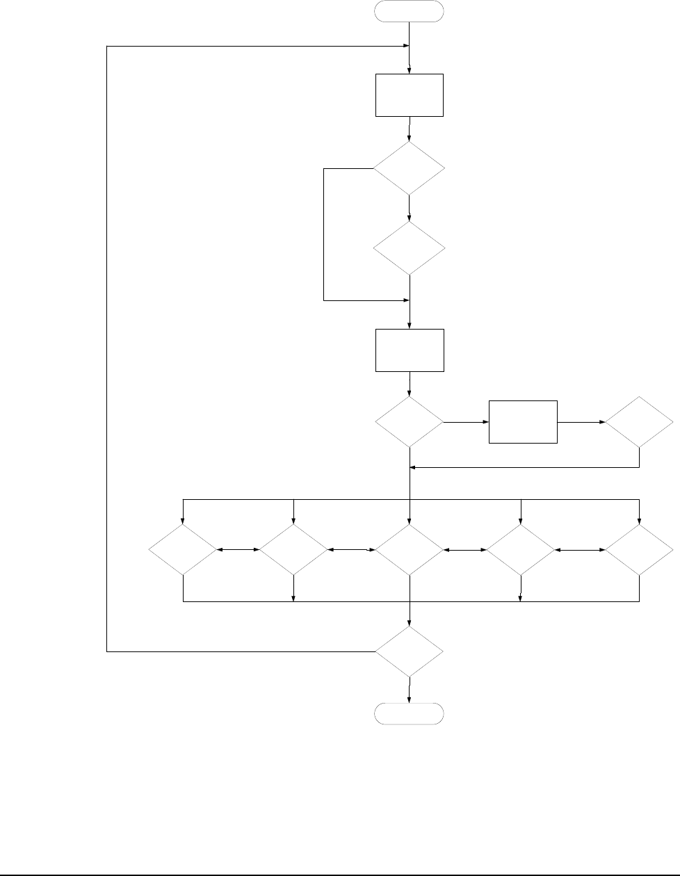
JETT•RFID+ Technical Reference Manual, MAN0352, Rev. A
5
-39
JETTRFIDp.dll Sample Flowchart
The following flowchart shows how you can use the JETTRFIDp.dll in an application:
Figure 5-1: JETTRFIDp.dll Sample Flow Chart
Initialize RFID
Configure Reader
Set Tag Type
& Flags
Enable
Sleep
Mode?
Enable
Wake
Mode?
Read Tag ID
Authorize Tag Write Key?
Read Tag
Data? Clear Data
Blocks? Write Tag
Data? Lock Data
Blocks? Get Tag
Info?
Next Tag?
Close RFID
NO
YES
If
MIFARE?
YES
NO
NO
YES
Same Tag Same Tag Same Tag
Same Tag

Application Development
5-40
JETTRFIDp.dll Error Codes
By default, all JETTRFIDp.dll functions return a Boolean pass/fail (TRUE/FALSE) result. In addition,
the JETTRFIDp.dll will return the following error codes to aide in application programming
development.
Initialization
The RFID+ module will return the following error codes, if an error occurs during initialization:
Value Description
100 Not initialized.
101 Invalid baud rate.
102 Could not open COM port.
103 Could not turn on auxiliary power.
104 Could not write to COM port.
105 Could not initialize module.
Parameters
The RFID+ module will return the following error codes, if an error occurs while passing function
parameters:
Value Description
200 Invalid flag setting.
201 Invalid tag type.
202 Tag ID is empty.
203 Invalid tag type for read/write command.
204 Invalid starting block (starting block range is 0–127).
205 Invalid number of data blocks (data block range is 1–16).
206 Tag data is empty.
207 Data byte size cannot be less than one.
208 Invalid sector number.
209 Invalid key length.
210 Invalid key type.
211 Invalid function type.
212 Invalid data (data range must be 0–255).

JETT•RFID+ Technical Reference Manual, MAN0352, Rev. A
5
-41
Read/Write
The RFID+ module will return the following error codes, if an error occurs while attempting to read,
write, clear or lock tag data:
Value Description
300 No tag ID found in RF field.
301 Not a valid tag ID, invalid tag type detected.
302 Could not read tag data.
303 Invalid starting block (starting block range is 0–127).
304 Invalid number of data blocks.
305 Could not set reader command.
306 Could not write tag data.
307 Invalid message length.
308 Could not lock data blocks or data blocks already locked.
309 Could not validate tag ID.
310 Could not authorize tag key.
311 Tag not authorized.
312 Could not write tag keys.
313 Could not get firmware version.
314 Extended function failed.
315 Tag type not supported in current firmware.
316 Tag does not support this function.
317 Sleep/Wake command failed.

Application Development
5-42
Keyboard Mapping
Kbtool.exe, designed to run on your development system, is a command line utility that creates a key
map file. This key map file will remap the current JETT keypad configuration externally (outside of an
application), when the unit boots up.
During the boot sequence, the JETT searches in the \Windows folder in ascending alphanumeric order
for existing key map files (identified by their “.RMT” extension). When the JETT encounters a file of this
type, it checks the key map ID number. If the ID number contained in the key map file matches the
number stored in the JETT’s hardware configuration block, the JETT uses that value in that file to map
to the keypad.
After creating your RMT file, you must copy it to the SystemCF folder on the JETT and deploy it to the
\Windows folder during boot up. See Launching Files at Startup for more information.
Default keypad template files (JET55KEY.TXT, JET31KEY.TXT and JET15KEY.TXT) are included with
the JETT•ce SDK. Copies of these files as well as configuration notes appear in Appendix B.
Syntax
JETTKBTOOL filename.ext
Option Description
filename.ext Specifies the name of the file containing the keypad template. The file name
must follow MS-DOS 8.3 naming conventions.
Default file names: 45-key keypad = Jet55key.txt, 30-key keypad = Jet31key.txt
15-key keypad = Jet15key.txt
Example
The following example executes KBTOOL using aJet55key.txt as it argument to create the file,
aJet55key.rmt for a 45-key keypad.
KBTOOL aJett55key.txt
Errors Messages
Message Description
Unable to open filename.ext. KBTOOL cannot find the specified file. The specified file is
named incorrectly
Unable to parse to scan code
‘XXX’ on NNN
The entry (XXX) is not a valid keyword on the specified line
(NNN)
Invalid line NNN The entry specified on line NNN is either misspelled, not
allowed or not formatted correctly
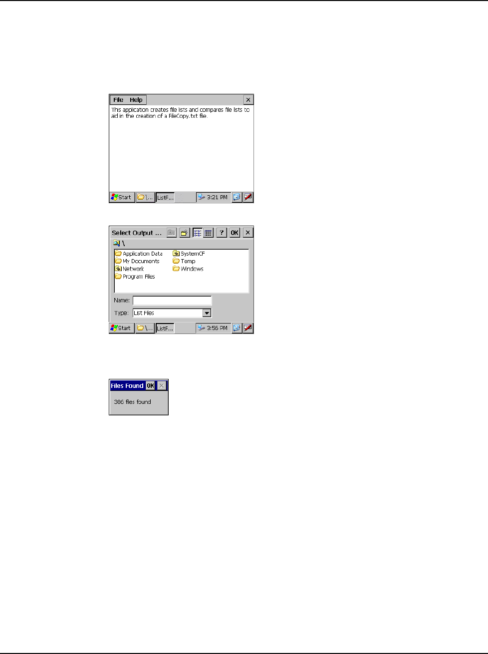
JETT•RFID+ Technical Reference Manual, MAN0352, Rev. A
5
-43
Tracking Self-Installed Files
ListFiles.exe is a utility program that enables you to compare the number of files before and after the
installation of self-extracting software on a JETT. An output file, which contains the differences, shows
the path and names of the added files, enables you to verify the components of the installed software as
well as their location. You can also incorporate listed in the output file with the contents of
FileCopy.F2C to launch the installed software at boot up.
1. On the JETT, navigate to the Windows folder and double-tap ListFiles.exe. The ListFiles.exe
dialog box appears.
2. On the menu bar, tap File and select New File List. The Select Output File dialog box appears.
3. Enter the name of the output file (such as before.txt) and tap OK (you should copy the file to
either System CF or a compact flash card to permanently store the file).ListFiles.exe will then
display the total number of files found on the JETT.
4. Tap OK to close the Files Found dialog.
5. Exit ListFiles.exe.
6. Copy and install the new software on the JETT.
7. After successfully installing the software, restart ListFiles.exe and following Steps 2 through 4
create another output file with a different file name (such as after.txt).
8. On the ListFiles menu bar, tap File and select Compare Lists. The Select Small List dialog box
appears.
9. Navigate to the folder that contains the file created in Steps 2 through 4 (i.e., before.txt), select
it and tap OK. The Select Larger List dialog box appears.
10. Navigate to the folder that contains the file created in Step 7 (i.e., after.txt), select it and tap
OK. The Select Output File dialog box appears.
11. Enter the name of the output file (such as diff.txt) that will contain the list of differences and
tap OK. ListFiles.exe will then display the total number of difference found between the first
and second files.
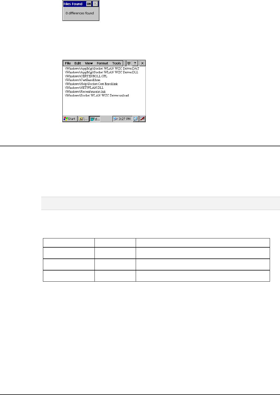
Application Development
5-44
12. Tap OK to close the Files Found dialog.
13. Exit ListFiles.exe.
14. Navigate to the folder that contains the output file (i.e., diff.txt) and double-tap it to view the
contents. For example:
Launching Files at Startup
You can create an ASCII text input file to automatically copy files and create folders when booting up
the JETT.
During the boot up process, the JETT looks in the \SystemCF folder for the FileCopy.F2C file, and if
found, opens the file and then parses and executes its contents.
When the file copy function executes, it creates the FCLog.txt file in the \SystemCF folder. This log file
will contain any errors encountered during the execution of the FileCopy.F2C file.
Note: the “F2C” file extension applies to JETTs with OS Versions 0.70 and above. Previous versions must still
use the “txt” file extension.
FileCopy.F2C Commands
Each line in the FileCopy.F2C file must begin with one of the following command line arguments:
Function Command Arguments
Copy File copy <\path\source_file> <\path\file_name>
Make Directory md or mkdir <\path\directory>
Comments ;
If a file or directory name includes one or more spaces, the whole path must appear within quotes. For
example:
copy \systemcf\helloworld.exe "\program files\helloworld.exe"
Example
In the example below, the first line does not require quotes since neither the source path nor the
destination path include a space character. However, the second and third lines do require quotes
because the folder name “My App” contains a space character.
; install helloword app
copy \systemcf\mfcce.dll \windows\mfcce400d.dll
md "\My Apps\"
copy \systemcf\helloworld.exe "\ My Apps\helloworld.exe"

JETT•RFID+ Technical Reference Manual, MAN0352, Rev. A 6-1
Chapter 6: Troubleshooting
Problem My JETT does not respond when I press the power button.
Solutions Is the unit in Suspend mode?
If battery-powered, check the batteries.
Are all cables connected properly:
• Is the power supply plugged into an active AC outlet?
• Is the power connector securely plugged into the JETT?
Problem I changed my system settings, but when I turn on the JETT my settings are gone.
Solution You must save the registry after making any system or configuration changes.
Problem I transferred files to the JETT from my host computer, but when I turn on the JETT
my transferred files are missing.
Solution To store transferred files permanently, you must file copy the files into internal flash
memory or a compact flash card.
Occasionally, transferred files can be hidden from view, double-tap My Computer,
select Options from the View menu and clear all boxes.
Problem I cannot connect to the development system using ActiveSync.
Solutions Did you install ActiveSync using the Administrator account?
Check the cable connections.
Check the serial communications configuration.
Make sure the correct COM port is available.
In ActiveSync, check the Connection Settings for the connection type you are using
(USB, Serial or Ethernet).
Problem The screen is too light or too dark.
Solution Adjust the brightness via the brightness control in the Control Panel.

Troubleshooting
6-2
Problem The stylus is not responding properly.
Solution The screen is not calibrated correctly to interpret the screen taps. You need to
recalibrate the screen.
Problem The JETT acts slowly.
Solutions The unit may be short of program memory or storage memory.
Increase the amount of storage or program memory through the System control in
the Control Panel.
You can also delete any unnecessary files.
Problem I get little or no sound from the JETT.
Solution Adjust the volume and sound properties via the Volume and Sound control in the
Control Panel.
Problem The JETT does not recognize a compact flash or device card.
Solution The card is not installed or seated properly.
Reinstall the card. There may be an unstable connection between the card and the
JETT.
Remove the card, clean the edge connector with a soft dry cloth, and reinstall the
card.
Problem The JETT goes into auto-suspend after a short period of inactivity.
Solution As a default, the device will auto-suspend after two minutes of inactivity while
running on batteries and after thirty minutes of inactivity when running on AC
power.
Adjust the power management properties via the Power control in the Control
Panel.
Problem No sound is heard when you tap the touch screen or press a key.
Solution Volume setting is low or turned off.
Check the volume slider in the Volume & Sound properties dialog box in the
Control Panel.

JETT•RFID+ Technical Reference Manual, MAN0352, Rev. A A-1
Appendix A: Specifications
Power
Recharge Voltage: 11 to 18 VDC, 1.5A (North America Only)
Battery Type: Nickel Metal Hydride Rechargeable (or 6 AA alkaline batteries)
Current Rating: 2 Amp Maximum
Voltage: 7.2 Volts
Capacity: 1400 mAh
Display
Supertwist Nematic Liquid Crystal TFT Touch Screen with white LED backlight
Resolution: 320 x 240 pixels QVGA color
Environmental
Operating Temperature: 0°C to +50°C
Storage Temperature: -25°C to +70°C
Charging Temperature: 0°C to + 40°C
Humidity: 5-95% Non-condensing
IP Rating: 65 (Available as an option)
CPU
Type: Intel PXA255 processor with XScale technology
Instruction Set Architecture: ARM v.5TE
Speed: 200 MHz (400 MHz optional)
Operating System: Windows CE .NET 4.2 Professional
Memory and Mass Storage
SDRAM: 64MB
Internal Compact Flash: 64 MB standard (16MB reserved for OS), upgradeable to 128MB
Optional: Compact flash card slot
RFID Module
Multi-protocol read/write support for the following 13.56MHz RFID tag types:
ISO15693: Texas Instruments Tag-It HF-I, Philips I•Code SLI
ISO14443: Philips Standard Card IC MF1 IC S50 (MIFARE A 1k), Philips Standard Card IC
MF1 IC S70 (MIFARE A 4k), Philips Contactless Single-trip Ticket IC MF0 IC U1 (MIFARE
Ultraalight), Atmel (MIFARE Type B)
Read Range: 3.152-3.546 inches (80-90 mm)
Output Power Measurement: 22.8 dbm = 200 mW
Indicators
5 Modifier Key/Programmable LEDs
Charge/Low Battery Indicator (battery-powered units only)
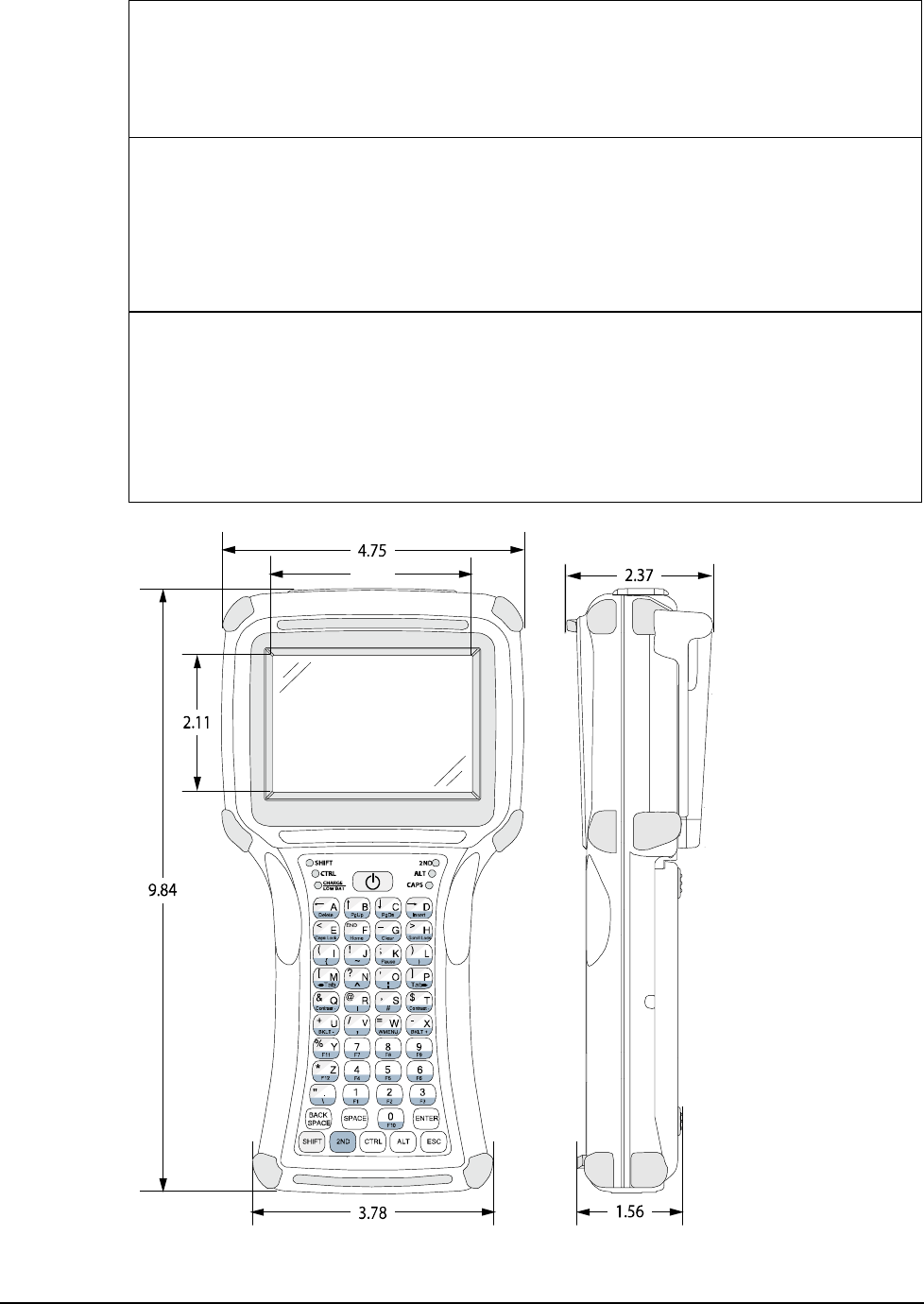
Troubleshooting
A-2
User Input
Touch Screen
Key Pad: 45-Key membrane (9 rows x 5 columns) or 15-key elastomeric (5 x 3)
Feedback: Tactile and audible
Optional: LED backlighting
Interface Capability
One available serial port configured for RS-232 that can also provide input power (11–18VDC)
and recharging capability.
Optional interface connectors (available at time of factory configuration) include the
JETT•connect system, DE-9 male or female connectors and a six-pin modular connector.
Interface connections (available at time of factory configuration) can optionally provide output at
5 VDC to operate peripheral devices.
Physical Dimensions
Height (H): 9.84 Inches (250 mm)
Width (W): 4.75 Inches (120.7 mm)
Depth (D): 2.37 Inches (60.2 mm)
Weight with NiMH Batteries: 33 Ounces (935.5 grams)
Weight with Alkaline Batteries: 32 Ounces (907.2 grams)
Weight without Batteries: 27 Ounces (765.4 grams)
Figure 6-1: Case Dimensions
2.82
Specifications subject to change
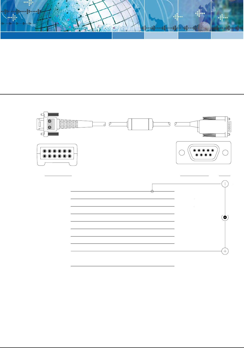
JETT•RFID+ Technical Reference Manual, MAN0352, Rev. A B-1
Appendix B: Signal and Pin Assignments
JETT•connect Cables
Figures B-1 and B-2 list the standard RS-232 signal and pin assignments for the JETT•connect cables.
Figure 6-2: 91708 Cable (Male DE9) RS-232 Signal and Pin Assignments
JETT• Connect DE 9 Connector
9
8
76
54321
9
8
7
6
5
4
3
2
111
1012
Pin 1 (Reserved)
Pin 2 (GND)
Pin 3 (RI)
Blue
Pin 4 (CTS)
Pin 5 (DTR)
Pin 6 (TXD)
Pin 7 (DSR)
Pin 8 (RTS)
Pin 9 (DCD)
Pin 10 (PWR)
Pin 11 (SHIELD)
Pin 12 (RXD)
Pin 5 (GND)
Pin 9 (RI)
Pin 8 (CTS)
Pin 4 (DTR)
Pin 3 (TXD)
Pin 1 (DCD)
Pin 2 (RXD)
Pin 6 (DSR)
Pin 7 (RTS)
Power
White w/Black Stripe
Gray
Black
Violet
Yellow
Brown
Red
Orange
White
Green
Viewed Facing
Connector
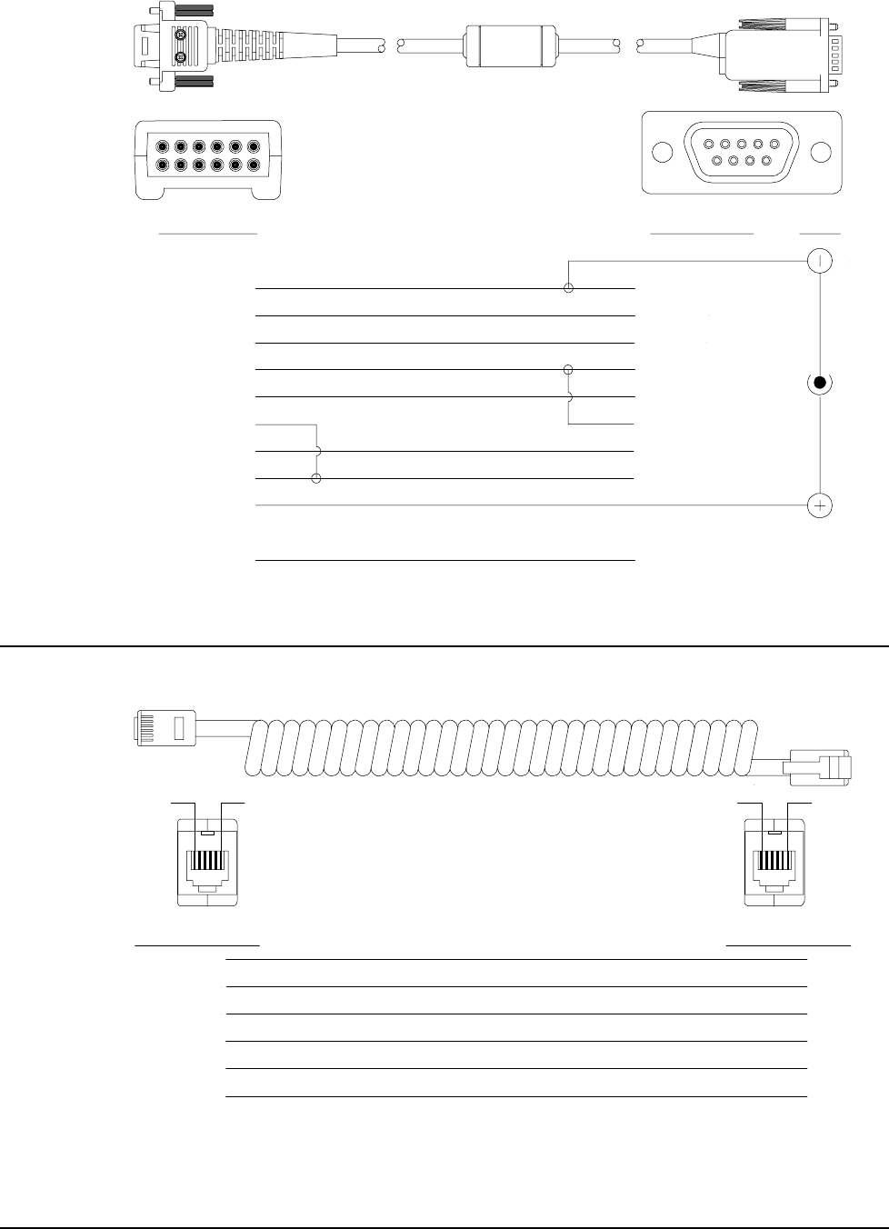
Troubleshooting
B-2
Figure 6-3: 91709 Cable (Female DE9) RS-232 Signal and Pin Assignments
JETT• Connect DE 9 Connector
9
8
76
54321
9
8
7
6
5
4
3
2
111
1012
Pin 1 (Reserved)
Pin 2 (GND)
Pin 3 (RI)
Pin 4 (CTS)
Pin 5 (DTR)
Pin 6 (TXD)
Pin 7 (DSR)
Pin 8 (RTS)
Pin 9 (DCD)
Pin 10 (PWR)
Pin 11 (SHIELD)
Pin 12 (RXD)
Pin 5 (GND)
Pin 9 (RI In)
Pin 7 (CTS In)
Pin 1 (DTR Out)
Pin 2 (TXD Out)
Pin 4 (DSR/DCD In)
Pin 3 (RXD In)
Pin 6 (DTR Out)
Pin 8 (RTS Out)
Power
Viewed Facing
Connector
Blue
Gray
Red
Orange
Green
Brown
Black
Violet
White
Yellow
White w\Black Stripe
Violet
1210 Series Modular Interface Cables
Figure B-3 lists the signal and pin assignments for 1210 series modular cables.
Figure 6-4: 1210 Series Modular Cable Signal and Pin Assignments
6-Pin Modular Jack
Pin 1 (Blue)
Pin 2 (Yellow)
Pin 3 (Green)
Pin 4 (Red)
Pin 5 (Black)
Pin 6 (White)
Pin 6
Pin 5
Pin 4
Pin 3
Pin 2
Pin 1
Pin 6
6-Pin Modular Jack
Pin 6
Pin 1
Pin 1
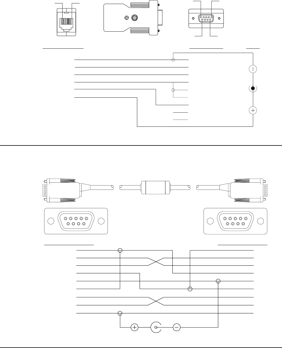
JETT•RFID+ Technical Reference Manual, MAN0352, Rev. A B-3
Modular Cable Adapters
Pin descriptions assume connection through reversing cables (1210-7, 1210-15) to JETT.
CELAT-P Adapter
Figure B-4 lists the signal and pin assignments for the CELAT-P adapter.
Figure 6-5: CELAT-P Adapter
6-Pin Modular Jack DE 9 Connector
Pin 5 (Common)
Pin 2 (Data Out)
Pin 3 (Data In)
Pin 1 (CTS)
Pin 6 (RTS)
Pin 4
Pin 9 (RI)
Pin 8 (Handshake Out)
Pin 7 (Handshake Out)
Power
Viewed Facing
Connector
Pin 1
Pin 6
Pin 5
Pin 1
Pin 9
Pin 6
Pin 1 (Blue)
Pin 2 (Yellow)
Pin 3 (Green)
Pin 4 (Red)
Pin 5 (Black)
Pin 6 (White)
Null Modem Cable
Figure B-5 lists the signal and pin assignments for Two Technologies’ 14375 DE-9 Female to DE-9
Female null modem cable. Please note that this cable differs from standard null modem cables in that it
use Pin 9 for input power for the JETT.
Figure 6-6: DE-9 Female to DE-9 Female Null Modem Cable
9
8
76
54321
Female DE9 Connector
Pin 1 (Blue)
Pin 2 (Green)
Pin 3 (Yellow)
Pin 4 (Orange)
Pin 5 (Gray)
Pin 6 (Blue)
Pin 7 (Red)
Pin 8 (Violet)
Pin 9 (Brown)
Pin 7
Pin 9
Pin 8
Pin 3
Pin 6
Pin 5
Pin 4
Pin 2
Pin 1
Power Jack
Female DE9 Connector
Viewed Facing
Connector
9
8
76
54321

JETT•RFID+ Technical Reference Manual, MAN0352, Rev. A C-1
Appendix C: Keyboard Mapping Files
Allowed Values
The following table lists the allowable values and the names of allowable values that you can map to a
keypad.
Table C-1: Allowed Values in Key Map Files
A V CARET F9 NUMPAD1 SEMICOLON
B W CLEAR F10 NUMPAD2 SHIFT
C X COLON F11 NUMPAD3 SLASH
D Y COMMA F12 NUMPAD4 SPACE
E Z CONTROL FUNCTION NUMPAD5 STAR
F ( DELETE HASH NUMPAD6 SUBTRACT
G ) DOLLAR HOME NUMPAD7 TAB
H [ DOUBLEQUOTE INSERT NUMPAD8 TILDA
I ] DOWN LEFT NUMPAD9 UNDERLINE
J { END KEY0 PAGEDOWN UP
K } EQUAL KEY1 PAGEUP USER_DEF1
L < ESCAPE KEY2 PAUSE USER_DEF2
M > EXCLAMATION KEY3 PERCENT USER_DEF3
N ADD F1 KEY4 PERIOD USER_DEF4
O ALT F2 KEY5 PIPE USER_DEF5
P AMPERSAND F3 KEY6 PRINT USER_DEF6
Q AT F4 KEY7 QUESTION USER_DEF7
R BACKQUOTE F5 KEY8 QUOTE USER_DEF8
S BACKSLASH F6 KEY9 RETURN USER_DEF9
T BACKSPACE F7 NUMLOCK RIGHT USER_DEF10
U CAPSLOCK F8 NUMPAD0 SCROLL WINMENU
Scan codes “USER_DEF1” through “USER_DEF10” can produce some proprietary action, such as
backlight adjustment, display rotation, etc. For each user-defined key-function (except as noted below),
you must supply the appropriate code in the keyboard driver to produce the desired effect.
"USER_DEF3" defines the Backlight+ key and "USER_DEF4" defines the Backlight– key.
The "FUNCTION" keyword identifies those function accessed through the "2nd" key. The “RETURN"
keyword identifies the "ENTER" key. The "WINMENU" keyword produces the Windows "Start" menu.
The number in COLS must always be set to five regardless of the actual number of columns (applies to
15-key keypads as well).
Do not change the ID number, it must match the number stored in the JETT’s hardware configuration
block.

Troubleshooting
C-2
45-Key Key Map
# 55 Key JettCE keyboard for P/N 11406 Rev A. keypad
# The keyword "FUNCTION" is used for the "2nd" key.
# The keyword "RETURN" is used for the "ENTER" key.
# "USER_DEF1" defines the Contrast+ key
# "USER_DEF2" defines the Contrast- key
# "USER_DEF3" defines the Backlight-INCREASE key
# "USER_DEF4" defines the Backlight-DECREASE key
# "WINMENU" produces the Windows "Start" menu.
# The line and the end of the line
ROWS 11
COLS 5
# The id of the keyboard.
ID 55
# The basic scan codes.
# Row,Col,Scan Code
SCANCODE 0, 0 -> A SCANCODE 0, 1 -> B SCANCODE 0, 2 -> C
SCANCODE 0, 3 -> D SCANCODE 1, 0 -> E SCANCODE 1, 1 -> F
SCANCODE 1, 2 -> G SCANCODE 1, 3 -> H SCANCODE 2, 0 -> I
SCANCODE 2, 1 -> J SCANCODE 2, 2 -> K SCANCODE 2, 3 -> L
SCANCODE 3, 0 -> M SCANCODE 3, 1 -> N SCANCODE 3, 2 -> O
SCANCODE 3, 3 -> P SCANCODE 4, 0 -> Q SCANCODE 4, 1 -> R
SCANCODE 4, 2 -> S SCANCODE 4, 3 -> T SCANCODE 5, 0 -> U
SCANCODE 5, 1 -> V SCANCODE 5, 2 -> W SCANCODE 5, 3 -> X
SCANCODE 6, 0 -> Y SCANCODE 6, 1 -> KEY7 SCANCODE 6, 2 -> KEY8
SCANCODE 6, 3 -> KEY9 SCANCODE 7, 0 -> Z SCANCODE 7, 1 -> KEY4
SCANCODE 7, 2 -> KEY5 SCANCODE 7, 3 -> KEY6 SCANCODE 8, 0 -> PERIOD
SCANCODE 8, 1 -> KEY1 SCANCODE 8, 2 -> KEY2 SCANCODE 8, 3 -> KEY3
SCANCODE 9, 0 -> BACKSPACE SCANCODE 9, 1 -> SPACE SCANCODE 9, 2 -> KEY0
SCANCODE 9, 3 -> RETURN SCANCODE 10, 0 -> SHIFT SCANCODE 10, 1 -> FUNCTION
SCANCODE 10, 2 -> CONTROL SCANCODE 10, 3 -> ALT SCANCODE 10, 4 -> ESCAPE
# Table 0 is always the unshifted values.
TABLE 0, basic, UNSHIFTED
TABLE 1, func, FUNCTION
TABLE 2, shift, SHIFT
# Func remapping table.
REMAPPING func, A -> DELETE REMAPPING func, B -> PAGEUP
REMAPPING func, C -> PAGEDOWN REMAPPING func, D -> INSERT
REMAPPING func, E -> CAPSLOCK REMAPPING func, F -> HOME
REMAPPING func, G -> CLEAR REMAPPING func, H -> SCROLL
REMAPPING func, I -> { REMAPPING func, J -> TILDA
REMAPPING func, K -> PAUSE REMAPPING func, L -> }
REMAPPING func, M -> BACKTAB REMAPPING func, N -> CARET
REMAPPING func, O -> COLON REMAPPING func, P -> TAB
REMAPPING func, Q -> USER_DEF2 REMAPPING func, R -> PIPE
REMAPPING func, S -> HASH REMAPPING func, T -> USER_DEF1
REMAPPING func, U -> USER_DEF4 REMAPPING func, V -> COMMA
REMAPPING func, W -> WINMENU REMAPPING func, X -> USER_DEF3
REMAPPING func, Y -> F11 REMAPPING func, Z -> F12
REMAPPING func, PERIOD -> BACKSLASH REMAPPING func, KEY7 -> F7
REMAPPING func, KEY8 -> F8 REMAPPING func, KEY9 -> F9

JETT•RFID+ Technical Reference Manual, MAN0352, Rev. A C-3
REMAPPING func, KEY4 -> F4 REMAPPING func, KEY5 -> F5
REMAPPING func, KEY6 -> F6 REMAPPING func, KEY1 -> F1
REMAPPING func, KEY2 -> F2 REMAPPING func, KEY3 -> F3
REMAPPING func, KEY0 -> F10
# Shift remapping table.
REMAPPING shift, A -> LEFT REMAPPING shift, B -> UP
REMAPPING shift, C -> DOWN REMAPPING shift, D -> RIGHT
REMAPPING shift, E -> < REMAPPING shift, F -> END
REMAPPING shift, G -> UNDERLINE REMAPPING shift, H -> >
REMAPPING shift, I -> ( REMAPPING shift, J -> EXCLAMATION
REMAPPING shift, K -> SEMICOLON REMAPPING shift, L -> )
REMAPPING shift, M -> [ REMAPPING shift, N -> QUESTION
REMAPPING shift, O -> BACKQUOTE REMAPPING shift, P -> ]
REMAPPING shift, Q -> AMPERSAND REMAPPING shift, R -> AT
REMAPPING shift, S -> QUOTE REMAPPING shift, T -> DOLLAR
REMAPPING shift, U -> SUBTRACT REMAPPING shift, V -> SLASH
REMAPPING shift, W -> EQUAL REMAPPING shift, X -> ADD
REMAPPING shift, Y -> PERCENT REMAPPING shift, Z -> STAR
REMAPPING shift, PERIOD -> DOUBLEQUOTE #REMAPPING shift, KEY7 ->
#REMAPPING shift, KEY8 -> #REMAPPING shift, KEY9 ->
#REMAPPING shift, KEY4 -> #REMAPPING shift, KEY5 ->
#REMAPPING shift, KEY6 -> #REMAPPING shift, KEY1 ->
#REMAPPING shift, KEY2 -> #REMAPPING shift, KEY3 ->
#REMAPPING shift, KEY0 ->

Troubleshooting
C-4
30-Key Key Map
# 31 Key JettCE keyboard definition file
# The keyword "FUNCTION" is used for the "2nd" key.
# The keyword "RETURN" is used for the "ENTER" key.
# "USER_DEF1" defines the Contrast+ key
# "USER_DEF2" defines the Contrast- key
# "USER_DEF3" defines the Backlight-INCREASE key
# "USER_DEF4" defines the Backlight-DECREASE key
# "WINMENU" produces the Windows "Start" menu.
# The line and the end of the line
ROWS 10
COLS 5
# The id of the keyboard.
ID 31
# Table 0 is always the unshifted values.
TABLE 0, basic, UNSHIFTED
TABLE 1, shift, SHIFT
# The basic scan codes.
# Row,Col,Scan Code
SCANCODE 0, 0 -> A SCANCODE 0, 1 -> B SCANCODE 0, 2 -> C
SCANCODE 1, 0 -> D SCANCODE 1, 1 -> E SCANCODE 1, 2 -> F
SCANCODE 2, 0 -> G SCANCODE 2, 1 -> H SCANCODE 2, 2 -> I
SCANCODE 3, 0 -> J SCANCODE 3, 1 -> K SCANCODE 3, 2 -> L
SCANCODE 4, 0 -> M SCANCODE 4, 1 -> N SCANCODE 4, 2 -> O
SCANCODE 5, 0 -> P SCANCODE 5, 1 -> Q SCANCODE 5, 2 -> R
SCANCODE 6, 0 -> S SCANCODE 6, 1 -> T SCANCODE 6, 2 -> U
SCANCODE 7, 0 -> V SCANCODE 7, 1 -> W SCANCODE 7, 2 -> X
SCANCODE 8, 0 -> Y SCANCODE 8, 1 -> Z SCANCODE 8, 2 -> ESCAPE
SCANCODE 9, 0 -> SHIFT SCANCODE 9, 1 -> SPACE SCANCODE 9, 2 -> RETURN
# Shift remapping table.
REMAPPING shift, A -> LEFT REMAPPING shift, B -> DOWN
REMAPPING shift, C -> RIGHT REMAPPING shift, D -> SUBTRACT
REMAPPING shift, E -> UP REMAPPING shift, F -> ADD
REMAPPING shift, G -> TAB REMAPPING shift, H -> QUESTION
REMAPPING shift, I -> COMMA REMAPPING shift, J -> BACKSLASH
REMAPPING shift, K -> COLON REMAPPING shift, L -> SLASH
REMAPPING shift, M -> USER_DEF4 REMAPPING shift, N -> STAR
REMAPPING shift, O -> USER_DEF3 REMAPPING shift, P -> KEY7
REMAPPING shift, Q -> KEY8 REMAPPING shift, R -> KEY9
REMAPPING shift, S -> KEY4 REMAPPING shift, T -> KEY5
REMAPPING shift, U -> KEY6 REMAPPING shift, V -> KEY1
REMAPPING shift, W -> KEY2 REMAPPING shift, X -> KEY3
REMAPPING shift, Y -> ALT REMAPPING shift, Z -> KEY0
REMAPPING shift, ESCAPE -> PERIOD REMAPPING shift, SPACE -> BACKSPACE

JETT•RFID+ Technical Reference Manual, MAN0352, Rev. A C-5
15-Key Key Map
# Copyright (c) 2003 Two Technologies Corporation. All rights reserved.
# File: JET15Key.txt
#
# 15 Key JETT.ce keyboard, REV 1
# The keyword "FUNCTION" is used for the "2nd" key.
# The keyword "RETURN" is used for the "ENTER" key.
# "USER_DEF1" defines the Contrast+ key
# "USER_DEF2" defines the Contrast- key
# "USER_DEF3" defines the Backlight-On key
# "USER_DEF4" defines the Backlight-Off key
# "WINMENU" produces the Windows "Start" menu.
# The number of rows and columns.
# Note: COLS MUST ALWAYS be a 5
ROWS 5
COLS 5
# The id of the keyboard.
ID 15
# The basic scan codes.
# Row,Col,Scan Code
SCANCODE 0, 0 -> TAB SCANCODE 0, 1 -> UP SCANCODE 0, 2 -> ALT
SCANCODE 1, 0 -> LEFT SCANCODE 1, 1 -> BACKSLASH SCANCODE 1, 2 -> RIGHT
SCANCODE 2, 0 -> SUBTRACT SCANCODE 2, 1 -> DOWN SCANCODE 2, 2 -> ADD
SCANCODE 3, 0 -> ESCAPE SCANCODE 3, 1 -> PERIOD SCANCODE 3, 2 -> RETURN
SCANCODE 4, 0 -> FUNCTION SCANCODE 4, 1 -> CONTRO SCANCODE 4, 2 -> SPACE
# Table 0 is always the unshifted values.
TABLE 0, basic, UNSHIFTED
TABLE 1, func, FUNCTION
TABLE 2, shift, SHIFT
# func remapping table.
REMAPPING func, TAB -> KEY1 REMAPPING func, UP -> KEY2
REMAPPING func, ALT -> KEY3 REMAPPING func, LEFT -> KEY4
REMAPPING func, BACKSLASH -> KEY5 REMAPPING func, RIGHT -> KEY6
REMAPPING func, SUBTRACT -> KEY7 REMAPPING func, DOWN -> KEY8
REMAPPING func, ADD -> KEY9 REMAPPING func, ESCAPE -> USER_DEF4
REMAPPING func, PERIOD -> KEY0 REMAPPING func, RETURN -> USER_DEF3
#REMAPPING func, FUNCTION -> REMAPPING func, CONTROL -> WINMENU
REMAPPING func, SPACE -> BACKSPACE

JETT•RFID+ Technical Reference Manual, MAN0352, Rev. A D-1
Appendix D: Supported RFID Tag Formats
Texas Instruments Tag-It HF-I Tag Format
The Texas Instruments Tag-It HF-I RFID tag is ISO/IEC 15693 compliant and has 2K bits (256 bytes) of
user memory available for read/write operations
A 64-bit ID (factory programmed) uniquely identifies each Tag-It HF-I chip.
TID 0xE0 0x07 Unique Tag ID - 48 bits (6 bytes)
Philips I·Code SLI Tag Format
The Philips I·Code SLI RFID tag is ISO/IEC 15693 compliant and has 896 bits (112 bytes) of user
memory available for read/write operations
Block # 32 bits (4 bytes per block)
0 (0x00) Data Data Data Data
1 (0x01) Data Data Data Data
2 (0x02) Data Data Data Data
.
.
.
.
.
.
.
.
.
.
.
.
.
.
.
26 (0x1A) Data Data Data Data
27 (0x1B) Data Data Data Data
A 64-bit ID (factory programmed) uniquely identifies each I·Code SLI chip (SL2 ICS20).
TID 0xE0 0x04 0x01 Unique Tag ID - 40 bits (5 bytes)
Block # 32 bits (4 bytes per block)
0 (0x00) Data Data Data Data
1 (0x01) Data Data Data Data
2 (0x02) Data Data Data Data
.
.
.
.
.
.
.
.
.
.
.
.
.
.
.
62 (0x3E) Data Data Data Data
63 (0x3F) Data Data Data Data

Troubleshooting
D-2
Philips MIFARE A 1k Tag Format
The Philips Standard Card IC MF1 IC S50 RFID tag is ISO 14443 A compliant and has 1024 x 8-bit of
EEPROM memory organized in 16 sectors with 4 blocks of 16 bytes each.
In the erased state, the EEPROM cells are read logical “0,” in the written state as a logical “1.”
Sector Block 1 2 3 4 5 6 7 8 9 10 11 12 13 14 15
3 Key A Access Bits Key B
2 D D D D D D D D D D D D D D D
1 D D D D D D D D D D D D D D D
15
0 D D D D D D D D D D D D D D D
.
.
.
.
.
.
.
.
.
.
.
.
.
.
.
.
.
.
.
.
.
.
.
.
.
.
.
.
.
.
.
.
.
.
.
.
.
.
.
.
.
.
.
.
.
.
.
.
.
.
.
3 Key A Access Bits Key B
2 D D D D D D D D D D D D D D D
1 D D D D D D D D D D D D D D D
2
0 D D D D D D D D D D D D D D D
3 Key A Access Bits Key B
2 D D D D D D D D D D D D D D D
1 D D D D D D D D D D D D D D D
1
0 Manufacturer Block
Notes: D indicates the user area.

JETT•RFID+ Technical Reference Manual, MAN0352, Rev. A D-3
Philips MIFARE A 4k Tag Format
The Philips Standard Card IC MF1 IC S70 RFID tag is ISO 14443 A compliant and has 4k byte EEPROM
memory organized in 32 sectors with 4 blocks, and 8 sectors with 16 blocks each. One block consists of
16 bytes.
In the erased state, the EEPROM cells are read logical “0,” in the written state as a logical “1.”
Sector
Block 1 2 3 4 5 6 7 8 9 10 11 12 13 14 15
15 Key A Access Bits Key B
.
.
.
.
.
.
.
.
.
.
.
.
.
.
.
.
.
.
.
.
.
.
.
.
.
.
.
.
.
.
.
.
.
.
.
.
.
.
.
.
.
.
.
.
.
.
.
.
1 D D D D D D D D D D D D D D D
39
0 D D D D D D D D D D D D D D D
.
.
.
.
.
.
.
.
.
.
.
.
.
.
.
.
.
.
.
.
.
.
.
.
.
.
.
.
.
.
.
.
.
.
.
.
.
.
.
.
.
.
.
.
.
.
.
.
.
.
.
15 Key A Access Bits Key B
.
.
.
.
.
.
.
.
.
.
.
.
.
.
.
.
.
.
.
.
.
.
.
.
.
.
.
.
.
.
.
.
.
.
.
.
.
.
.
.
.
.
.
.
.
.
.
.
1 D D D D D D D D D D D D D D D
32
0 D D D D D D D D D D D D D D D
.
.
.
.
.
.
.
.
.
.
.
.
.
.
.
.
.
.
.
.
.
.
.
.
.
.
.
.
.
.
.
.
.
.
.
.
.
.
.
.
.
.
.
.
.
.
.
.
.
.
.
15 Key A Access Bits Key B
.
.
.
.
.
.
.
.
.
.
.
.
.
.
.
.
.
.
.
.
.
.
.
.
.
.
.
.
.
.
.
.
.
.
.
.
.
.
.
.
.
.
.
.
.
.
.
.
1 D D D D D D D D D D D D D D D
1
0 Manufacturer Data
Notes: D indicates the user area.
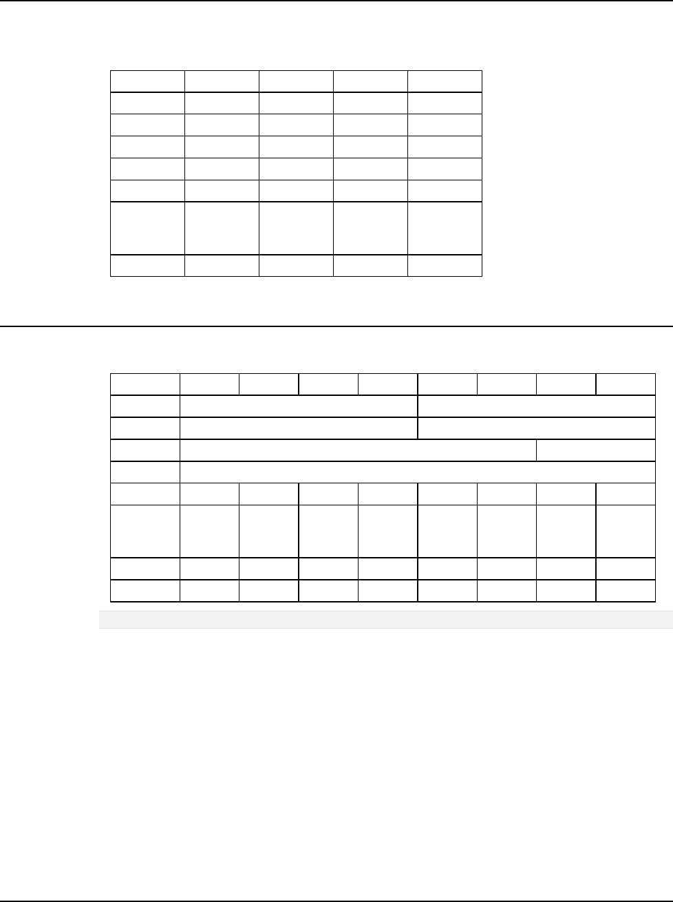
Troubleshooting
D-4
Philips MIFARE Ultralight Tag Format
This Philips Contactless Single-trip Ticket IC MF0 IC U1 tag is ISO 14443 A compliant and has 512 bits
of EEPROM memory organized in 16 blocks with 4 bytes each.
In the erased state, the EEPROM cells are read logical “0,” in the written state as a logical “1.”
Block # Byte 0 Byte 1 Byte 2 Byte 3
0 (0x00) Serial #0 Serial #1 Serial #1 BCC0
1 (0x01) Serial #3 Serial #4 Serial #5 Serial #6
2 (0x02) BCC1 Internal Lock 0 Lock1
3 (0x03) Counter #1 Counter #2 Counter #3 Counter #4
4 (0x04) Data Data Data Data
.
.
.
.
.
.
.
.
.
.
.
.
.
.
.
15 (0x0F) Data Data Data Data
Atmel ISO 14443 B Tag Format
The Atmel ISO 14443 B RFID tag has 1904 bits (238 bytes) available for user-defined purposes. Bytes
marked "---" are user-defined and are set to 0x00 upon shipment form Atmel.
Block # Byte 0 Byte 1 Byte 2 Byte 3 Byte 4 Byte 5 Byte 6 Byte 7
0 (0x00) Unique ID Lock Bits
1 (0x01) Application Data Reserved
2 (0x02) Reserved Counter
3 (0x03) Password
4 (0x04) --- --- --- --- --- --- --- ---
.
.
.
.
.
.
.
.
.
.
.
.
.
.
.
.
.
.
.
.
.
.
.
.
.
.
.
30 (0x1A) --- --- --- --- --- --- --- ---
31 (0x1B) --- --- --- --- --- --- --- ---
Note: Bytes marked “---“ are user-defined and are set to 0x00 upon shipment form Atmel.

JETT•RFID+ Technical Reference Manual, MAN0352, Rev. A I-1
Index
1
1210 Series Modular Cable ......................................2-5, B-2
15-Key Key Map...............................................................C-5
15-Key Keypad..................................................................3-6
2
2ND Key.............................................................................3-7
2ND Mode .........................................................................3-7
3
30-Key Key Map...............................................................C-4
30-Key Keypad..................................................................3-6
4
45-Key Key Map...............................................................C-2
45-Key Keypads ................................................................3-6
A
About RFID........................................................................1-2
About the JETT•RFID ......................................................1-2
About this Manual............................................................1-1
About Two Technologies.................................................1-1
ActiveSync .........................................................................5-1
Allowed Values in Key Map Files .................................C-1
ALT Key.............................................................................3-7
Application Development................................................5-1
Application Types.............................................................5-1
Atmel ISO 14443 B Tag Format..................................... D-4
AuthorizeTag......................................................... 5-23, 5-35
AuthorizeTagB ...................................................... 5-23, 5-36
Aux Switch.........................................................................4-1
Auxiliary Power..............................................................5-13
AuxSwitchIsOn ..................................................... 5-13, 5-15
B
Backlight.............................................................................4-1
Battery Compartment.......................................................2-2
Battery Indicator ...............................................................2-1
Battery Select .....................................................................4-1
Beep Driver Control........................................................5-13
Beep Select .........................................................................4-1
Bluetooth Device Properties............................................4-1
C
Cable Connections............................................................2-5
JETT•connect System 2-4
Case Dimensions .............................................................A-2
CE Keyboard..................................................................... 3-8
CeKeys ............................................................................... 3-8
CELAT-P Adapter.................................................... 2-5, B-3
CenterCeKeys ........................................................5-13, 5-17
Certificates.........................................................................4-1
Changing System Settings...............................................4-3
Charge\Low Battery Indicator.......................................3-2
Charge\Low Battery Indicator Functions.....................3-2
Charging the Unit............................................................. 3-1
CHG Indicator ..................................................................3-2
ClearDataBlocks ....................................................5-23, 5-31
CloseRFID...............................................................5-23, 5-27
Compact Flash Slot Cover...............................................2-3
Closed Position 2-3
Modified 2-3
Open Position 2-3
Connecting to a Mail Server............................................ 4-7
Connector Covers.............................................................1-4
Control Panel ....................................................................4-1
Control Panel Functions ..................................................4-1
CPU Specifications ..........................................................A-1
CPU Speed.........................................................................4-1
Creating a Wired Ethernet Network Connection.........4-6
Creating a Wireless Connection .....................................4-6
CTRL Key ..........................................................................3-7
D
Data Entry .........................................................................3-9
Date/Time.........................................................................4-1
DE-9 Female Metal Plug..................................................1-4
DE-9 Male Metal Plug......................................................1-4
DecBrightness ........................................................5-13, 5-14
Desktop Functions.......................................................... 3-10
Development Tools ..........................................................5-1
Dialing ...............................................................................4-1
Display........................................................................2-1, 4-1
Display Rotation...............................................................4-1
Display Specifications.....................................................A-1

Index
I-2
DisplayCeKeys...................................................... 5-13, 5-16
Displays..............................................................................1-3
Durability...........................................................................1-4
E
eMbedded Visual C++ 4.0 ...............................................5-1
Environmental Specifications.........................................A-1
F
FileCopy.F2C...................................................................5-43
FileCopy.F2C Commands..............................................5-44
Front Components and Indicators..................................2-1
Fully/Near Full Charge ...................................................3-2
G
GetFirmwareVersion............................................ 5-23, 5-24
GetMacAddress .................................................... 5-13, 5-18
GetNkBinVersion.................................................. 5-13, 5-22
GetTagInfo............................................................. 5-23, 5-28
Getting Started with eMbedded Visual C++ 4.0...........5-9
Building and Deploying the Application 5-11
Creating a Hello World Application 5-9
Storing the Application File 5-11
Getting Started with Visual Studio .NET.......................5-4
Building and Deploying the Application 5-6
Creating a Hello World Application 5-4
Creating a Redistributable CAB File 5-7
Preliminary Setup 5-4
H
HideCeKeys........................................................... 5-13, 5-16
High Power Charge..........................................................3-2
Hot Keys ............................................................................4-1
I
Inbox.................................................................................3-10
IncBrightness......................................................... 5-13, 5-14
Incorporating JETTce.dll Functionality........................5-13
Incorporating JETTRFIDp.dll Functionality................5-23
Indicator Specifications...................................................A-1
Indicators ...........................................................................1-3
Ingress Protection .............................................................1-4
InitRFID.................................................................. 5-23, 5-24
Input Panel ........................................................................4-2
Interface Capabilities........................................................1-3
Interface Specifications....................................................A-2
Internet Explorer.............................................................3-10
Internet Options................................................................4-2
IP65 .....................................................................................1-4
IsCeKeysDisplayed............................................... 5-13, 5-15
IsCeKeysRunning ................................................. 5-13, 5-15
ISO 14443 A tags .............................................D-2, D-3, D-4
ISO 14443 B tags...............................................................D-4
ISO 15693 ..........................................................................D-1
ISO/IEC 14443 A Tags .......................5-35, 5-36, 5-37, 5-38
ISO/IEC 14443 B Tags........................ 5-35, 5-36, 5-37, 5-38
J
JETT•ce SDK..................................................................... 5-1
JETT•connect Cable................................................. 2-5, B-1
RS-232 Signal and Pin Assignments
Male DE9 .................................................................. B-1
JETT•connect Plug........................................................... 1-4
JETT•connect System ...................................................... 2-4
JETT•RFID Components................................................. 2-1
JETT•RFID Features ........................................................1-3
JETTce.dll ........................................................................ 5-13
Functions
Auxiliary Power .......................................................5-13
Beep Driver Control .................................................5-13
Display Version Number..........................................5-13
Keypad Backlight Control........................................5-13
LEDs ........................................................................5-13
Return MAC Address...............................................5-13
Screen Brightness.....................................................5-13
Soft Keyboard (CeKeys) ..........................................5-13
Suspend Device........................................................5-13
Suspend Function Control ........................................5-13
JETTRFIDp.dll.................................................................5-23
Error Codes 5-40
Initialization .............................................................5-40
Parameters................................................................5-40
Read/Write ...............................................................5-41
Functions
AuthorizeTag............................................................5-23
AuthorizeTagB.........................................................5-23
ClearDataBlocks.......................................................5-23
CloseRFID................................................................5-23
GetFirmwareVersion................................................5-23
GetTagInfo ...............................................................5-23
InitRFID...................................................................5-23
LockDataBlocks.......................................................5-23
ReadTagData............................................................5-23
ReadTagDataB .........................................................5-23
ReadTagID ...............................................................5-23
SetReader .................................................................5-23
Sleep Mode...............................................................5-23
WakeMode ...............................................................5-23
WriteKey..................................................................5-23
WriteKeyB ...............................................................5-23
WriteTagData...........................................................5-23
WriteTagDataB ........................................................5-23
Sample Flow Chart 5-39
K
Kbtool.exe.......................................................................... 5-1
Key Repeat ........................................................................ 3-7
Keyboard ........................................................................... 4-2
Keyboard Mapping........................................................ 5-42
Keyboard Mapping Files........................................C-1, D-4
Allowed Values C-1
Keypad............................................................................... 2-1
Keypad Backlight Control............................................. 5-13
Keypads......................................................................1-3, 3-6
L
Launching Files at Startup ............................................ 5-44

JETT•RFID+ Technical Reference Manual, MAN0352, Rev. A I-3
LEDs ......................................................................... 2-1, 5-13
LedUpdate ............................................................. 5-13, 5-18
ListFiles.exe......................................................................5-43
LockDataBlocks..................................................... 5-23, 5-34
LOW BAT Indicator..........................................................3-2
M
Managed Code ..................................................................5-1
Memory and Mass Storage..............................................1-3
Memory and Mass Storage Specifications................... A-1
Microsoft WordPad ........................................................3-10
Modifier Keys....................................................................3-7
Modular Cable Adapters ................................................B-3
Modular to DE-9S Adapter..............................................2-5
Modular-to-Modular Cable.............................................2-5
My Computer ..................................................................3-10
My Documents................................................................3-10
N
Native Code.......................................................................5-1
Network and Dial-up Connections ................................4-2
Network Connections.......................................................4-6
Null Modem Cable .......................................................... B-3
O
On/Off Switch...................................................................2-1
Operating System..............................................................1-3
Operation ...........................................................................3-1
Overview............................................................................1-1
Owner.................................................................................4-2
P
Partnership ........................................................................4-9
Password............................................................................4-2
PC Connection...................................................................4-2
Persistent Registry ..........................................................4-12
Philips I·Code SLI Tags........................................................ D-1
Philips MIFARE A 1k Tags............................................ D-2
Philips MIFARE A 4k Tags............................................ D-3
Philips MIFARE Ultralight Tags ................................... D-4
Physical Dimensions....................................................... A-2
PlayTone ................................................................ 5-13, 5-20
Power.......................................................................... 3-1, 4-2
Power Management..........................................................3-4
Power Off...........................................................................3-4
Power On ...........................................................................3-3
Power Plug.........................................................................1-4
Power Requirements ...................................................... A-1
Power Status Icons..........................................................3-11
Power Supply ........................................................... 2-5, A-1
Power/Suspend Switch ...................................................3-3
Processor............................................................................1-3
R
ReadTagData ......................................................... 5-23, 5-29
ReadTagDataB....................................................... 5-23, 5-30
ReadTagID..............................................................5-23, 5-27
Rechargeable Battery Pack..............................................1-3
Recycle Bin ......................................................................3-10
Regional Settings..............................................................4-2
Related Documents .......................................................... 1-1
Remove Programs ............................................................4-2
Resetting the Registry ....................................................4-13
Return MAC Address ....................................................5-13
RFID Module.....................................................................2-2
RFID Read Range ............................................................. 3-9
RunCeKeys.............................................................5-13, 5-16
RunwayLEDs ..................................................................5-21
S
Saving Changes to the Registry....................................4-12
Screen Brightness............................................................5-13
SetReader................................................................5-23, 5-25
Setting Up Identification for Remote Networks...........4-6
SHIFT Key .........................................................................3-7
Shift Mode .........................................................................3-7
ShutDownCeKeys .................................................5-13, 5-17
Signal and Pin Assignments ...........................................B-1
SleepMode..............................................................5-23, 5-26
Soft Keyboard (CeKeys) ................................................5-13
Specifications ...................................................................A-1
Start Menu....................................................................... 3-11
Storage Manager...............................................................4-2
Stylus..................................................................................4-2
Supported RFID Tag Formats........................................D-1
Suspend Device ..............................................................5-13
Suspend Function Control ............................................5-13
Suspend Mode ..................................................................3-4
Suspend_Key_Lockout .........................................5-13, 5-20
Suspend_Key_Lockout_Off .................................5-13, 5-19
Suspend_Key_Lockout_On..................................5-13, 5-19
Suspend_Key_Lockout_State...............................5-13, 5-19
SuspendDevice ......................................................5-13, 5-21
System................................................................................4-2
SystemCF Folder.............................................................3-11
T
Taskbar ............................................................................3-10
Taskbar and Start Menu Settings....................................4-4
Texas Instruments Tag-It HF-I Tags .............................D-1
The Windows CE .NET Desktop.................................. 3-10
Torx screws .......................................................................2-3
Tracking Self-Installed Files.......................................... 5-43
Trickle Charge...................................................................3-2
Troubleshooting................................................................6-1
TurnAuxSwitchOff................................................5-13, 5-14
TurnAuxSwitchOn ................................................5-13, 5-14
U
User Input Specifications................................................A-2
Using ActiveSync .............................................................4-9
Initial Communication 4-9
Subsequent Communication 4-12

Index
I-4
Using eMbedded Visual C++ 4.0....................................5-8
Migrating Previous Version 5-8
System Requirements 5-8
Using the Compact Flash Slot .........................................4-5
Using the Remote Registry Editor ................................5-12
Using the RFID+ Module.................................................3-9
Using Visual Studio .NET...............................................5-2
.NET Compact Framework Limitations 5-3
Supported Languages 5-2
System Requirements 5-2
The .Net Compact Framework 5-2
V
VComAdj........................................................................... 4-2
Version Number............................................................. 5-13
Visual Studio .NET 2003.................................................. 5-1
W
WakeMode .............................................................5-23, 5-26
Windows CE Utilities for Visual Studio .NET 2003,.... 5-1
WriteKey.................................................................5-23, 5-37
WriteKeyB ..............................................................5-23, 5-38
WriteTagData.........................................................5-23, 5-32
WriteTagDataB ......................................................5-23, 5-33