Two Technologies JETTXL Hand Held Computer with Bluetooth User Manual JETT XL User s Guide
Two Technologies, Inc. Hand Held Computer with Bluetooth JETT XL User s Guide
Contents
- 1. Users Manual Revision D
- 2. Users Manual Revised
Users Manual Revised

MAN0359, REV. C
USER’S GUIDE

II

III
JETT•XL USER'S GUIDE
Document Number: MAN0359, Rev. C
Version Support: 5.0.062
Date of Last Revision: July 20, 2007
Copyright © 1998 – 2007 Two Technologies, Inc.
All rights reserved.
Printed in the United States of America
COPYRIGHTS AND TRADEMARKS
Two Technologies is a trademark and JETT is a registered trademark of Two Technologies, Inc.
Microsoft, Windows CE 5.0, Windows NT, Windows 2000, Windows XP, eMbedded Visual C++, Visual
Studio .NET 2003, Visual Studio 2005 and ActiveSync are either trademarks or registered trademarks of the
Microsoft Corporation.
Other products or company names mentioned herein may be the trademarks or registered trademarks of
their respective companies.
REPRODUCTION RIGHTS
This manual contains proprietary information. Permission to reproduce or otherwise use portions of the
material presented herein is explicitly given to Two Technologies VARs incorporating the JETT•XL into
their products. Please note that this publication contains material that may not be appropriate for disclosure
to some end users and that Two Technologies assumes no responsibility for technical support burdens
incurred, or any other consequences of VAR documentation decisions.
CHANGES AND ADDENDUM
Since Two Technologies is continuously improving the functionality and quality of its products, certain
information may not be included at the time of release of the printed manual. When this occurs, changed
material may be provided as separate sheets included with this manual or separately in the form of a change
package.
CONTACT INFORMATION
Two Technologies Incorporated
419 Sargon Way, Horsham, PA 19044
Phone: 215.441.5305
Fax: 215.441.0423
Web: www.2T.com
To contact Two Technologies by e-mail:
• Sales: sales@2T.com
• Customer Service: customersupport@2T.com
• Technical Support: techsupport@2T.com

IV
WARRANTY INFORMATION
Seller warrants that the product specified in this agreement are free of defects in materials and
workmanship, and shall conform to the latest specifications published prior to Buyer’s acceptance of the
agreement for a period of one year (effective August 1, 2007).
Product specifications as defined supersede previous specifications and are complete. Any parameter that is
not specifically defined in the specifications is expressly excluded from the warranty. This warranty does
not apply to any product which have been subject to misuse, accident, alteration, or if the unit has been
serviced by anyone other than an authorized representative of Seller.
Seller’s sole obligation to Buyer for products failing to meet specifications shall be, at Seller’s discretion, to
repair or replace the non-conforming device.
After receiving a Return Authorization (RA) number and a mailing address from Seller, a defective unit
covered under this warranty may be returned freight prepaid. Any replacement or repaired product shall
carry only the unexpired term of the warranty plus any the period required for repair.
If Buyer has been expressly designated as an Original Equipment Manufacturer (OEM) by Seller, the
warranty period shall commence upon the earlier date of (i) delivery to Buyer’s first customer, or (ii) 180
days from the original date of shipment by Seller. In the events that products for which: (a) Buyer has title
and, (b) have never been used, and (c) have been in the Buyer’s possession for more than 180 days and, (d)
have an unaltered date code attached, may for an established fixed fee which will not exceed ten percent
(10%) of the original purchase price, have the date code updated by the Seller and thereby reestablish those
products with a new warranty.
THE FOREGOING WARRANTY AND REMEDIES ARE EXCLUSIVE AND ARE MADE EXPRESSLY IN
LIEU OF ALL OTHER WARRANTIES EXPRESSED OR IMPLIED, EITHER IN FACT OR BY OPERATION
OF LAW, STATUTORY OR OTHERWISE, INCLUDING WARRANTIES OR MERCHANTABILITY AND
FITNESS FOR USE. TWO TECHNOLOGIES NEITHER ASSUMES NOR AUTHORIZES ANY OTHER
PERSON TO ASSUME FOR IT ANY OTHER LIABILITY IN CONNECTION WITH THE SALE,
INSTALLATION OR USE OF ITS PRODUCTS AND TWO TECHNOLOGIES MAKES NO WARRANTY
WHATSOEVER FOR PRODUCTS NOT MANUFACTURED BY TWO TECHNOLOGIES.
TWO TECHNOLOGIES SHALL NOT BE LIABLE FOR DAMAGES DUE TO DELAYS IN DELIVERIES OR
USE AND SHALL IN NO EVENT BE LIABLE FOR INCIDENTAL OR CONSEQUENTIAL DAMAGES OF
ANY KIND, WHETHER ARISING FROM CONTRACT, TORT OR NEGLIGENCE, INCLUDING, BUT NOT
LIMITED TO, LOSS OF PROFITS, LOSS OF GOODWILL, OVERHEAD OR OTHER LIKE DAMAGES.
To maintain your warranty and to avoid creating hazards, only qualified personnel should perform
authorized modifications to Two Technologies’ products. Two Technologies cannot assume responsibility
for any condition affecting the proper operation of this equipment that may result from unauthorized
modifications.
PRODUCT RETURNS
If, after inspection, you note any product damage or discrepancies, please contact us promptly within five
days of receipt. If the exterior of the package shows obvious signs of damage, please contact your carrier
directly.
All items returned to Two Technologies require a Return Material Authorization number (RMA). Please
contact Two Technologies’ Service department to request an RMA number.

V
REGULATORY NOTICES
FCC PART 15 CLASS A
This equipment has been tested and found to comply with the limits for a Class A digital device, pursuant to
Part 15 of the FCC Rules. These limits are designed to provide reasonable protection against harmful
interference when the equipment is operated in a commercial environment. This equipment generates, uses,
and can radiate radio frequency energy and, if not installed and used in accordance with the instruction
manual, may cause harmful interference to radio communications. Operation of this equipment in a
residential area is likely to cause harmful interference in which case the user will be required to correct the
interference at his/her own expense.
This device complies with part 15 of the FCC Rules. Operation is subject to the following two conditions: (1)
this device may not cause harmful interference, and (2) this device must accept any interference received,
including interference that may cause undesired operation.
FCC ID: RYJJETTXL
Two Technologies Incorporated
419 Sargon Way, Horsham, PA 19044
Phone: 215.441.5305
FCC SECTION 15.21
Changes or modifications to this unit not expressly approved by Two Technologies may void the user’s
authority to operate the equipment1.
WLAN COMPLIANCE
This device contains a Socket Communication, Inc.
Operation is subject to the following conditions: (1) This device may not cause harmful interference, and (2)
this device must accept any interference received, including interference that may cause undesired
operation.
CANADIAN DEPARTMENT OF COMMUNICATIONS
This digital apparatus does not exceed the Class A limits for radio noise emissions from digital apparatus
set out in the Radio Interference Regulations of the Canadian Department of Communications
Le présent appareil numérique n’émet pas de bruits radioélectrique dépassant les limites applicables aux
appareils numériques de la class A prescrites dans le Règlement sur le brouillage radioélectrique édicté par
le ministère des Communications du Canada.
INDUSTRY CANADA
Registration Number: 6103A-JETTXL
CENELEC (PENDING)
EMI Standards:
• EN 55022:1998 (CISPR22), Class A
• ETSI EN 300 330-2: 2001
EMC Standards:
• EN 55024: 1998
• ETSI EN 301489-1: 2002, 301489-3: 2002
• EN/IEC 61000-4-2, 61000-4-3, 61000-4-4
1. The plug-in Socket Communications Corp. Go Wi-Fi! P500 802.11g CF Compact Flash Card radio module is accessed by removing the battery and the 9
Phillips Head screws holding the two halves of the JETT case together.
RYJ-P500CF-1
P500 radio, FCC ID: , IC ID: 6103A -
and complies with Part 15 of the FCC rules.
P500CF1
To comply with FCC RF exposure compliance requirements during use, the antenna(s) used for
transmitters in this device must provide a separation distance of at least 20cm from all persons
(excluding hands/wrists/feet/ankles) and must not be co-located or operating in conjunction with
any other antenna or transmitter except for TX FCC ID: RYJ-P500CF-1.
Also Contains:
FCC ID: RYJ-P500CF-1
IC: 6103A-P500CF1
VI
WARNINGS
Changes or modifications to this unit not expressly approved by the party responsible for regulatory
compliance could void the user's authority to operate the equipment.
ELECTROSTATIC DISCHARGE (ESD)
Electrostatic discharge (static electricity) can have unpredictable adverse effects on any electronic device.
Although the design of this product incorporates extensive ESD-related precautions, ESD can still cause
problems. It is good practice to discharge static by touching a grounded metal object before inserting cards
or connecting devices.
La descarga electrostática (electricidad estática) puede tener efectos nocivos imprevisibles en cualquier
dispositivo electrónico. Aunque el diseño de este producto incorpora precauciones ESD-relacionadas
extensas, la lata de ESD todavía causa problemas. Es buena práctica descargar parásitos atmosféricos
tocando un objeto puesto a tierra del metal antes de insertar tarjetas o de conectar los dispositivos.
La décharge électrostatique (l'électricité statique) peut avoir des effets nuisibles imprévisibles sur n'importe
quel dispositif électronique. Bien que la conception de ce produit incorpore des précautions ESD-connexes
étendues, le bidon d'ESD posent toujours des problèmes. Il est dans de bons habitudes de décharger la
charge statique en touchant un objet au sol en métal avant d'insérer des cartes ou relier des dispositifs.
Elektrostatische Aufladung (statische Elektrizität, ESD) kann unvorhersehbare schädliche Auswirkungen
auf jedes elektronische Gerät haben. Obgleich das Design dieses Produktes umfangreiche ESD-
Schutzmassnahmen enthält, kann ESD dennoch Probleme verursachen. Vermeiden Sie statische Elektrizität,
indem Sie einen geerdeten Metallgegenstand beühren bevor Sie Karten einsetzen oder andere Geräte
anschliessen.
SERVICING INFORMATION
When servicing the unit, the plug (JETT•connect cable) is the disconnect device. Simply unplug the unit
before servicing.
Al mantener la unidad, el enchufe (cable de JETT•connect) es el dispositivo de la desconexión. Desenchufe
simplemente la unidad antes de mantener.
En entretenant l'unité, la prise (câble de JETT•connect) est le dispositif de débranchement. Débranchez
simplement l'unité avant l'entretien.
Bei Arbeiten am Gerät ist zuerst das Verbindungskabel (JETT•connect Kabel) am Gerät abzustecken (falls
vorhanden).
BATTERY REPLACEMENT
CAUTION! There is a risk of explosion if you replace the NiMH battery with an incorrect type. Only use the
NiMH battery supplied with your unit or a replacement NiMH battery supplied, recommended, or
approved by Two Technologies, Inc.
PRECAUCIÓN! Hay un riesgo de la explosión si usted substituye la batería de NiMH por un tipo
incorrecto. Utilice solamente la batería de NiMH provista de su unidad o una batería de NiMH del
reemplazo provista, recomendada, o aprobada por Two Technologies, Inc.
ATTENTION! Il y a un risque d'explosion si vous remplacez la batterie de NiMH avec un type incorrect.
Utilisez seulement la batterie de NiMH fournie avec votre unité ou une batterie de NiMH de remplacement
fournie, recommandée, ou approuvée par Two Technologies, Inc.
VORSICHT! Bei Verwendung von NiMH Akkus, die nicht durch Two Technologies, Inc. geliefert,
empfohlen oder genehmigt wurden besteht Explosionsgefahr! Benutzen Sie daher nur solche NiMH Akkus,
die mit dem Gerät geliefert wurden bzw. Ersatzakkus, die durch Two Technologies, Inc. geliefert,
empfohlen oder genehmigt wurden.

VII
BATTERY DISPOSAL
Dispose of batteries in a safe manner. The following are general guidelines for the safe use and disposal of
NiMH batteries:
• Replace a defective NiMH battery immediately as it could damage the unit.
• Do not throw the NiMH battery in trash that is disposed of in landfills as it contains heavy metals.
Recycle or dispose the NiMH battery of it as required by local ordinances or regulations.
• Do not disassemble, incinerate, short-circuit the NiMH battery or throw it into a fire. It can explode
and cause severe personal injury.
• Excessive discharge damages a NiMH battery. Recharge the NiMH battery when your unit
indicates low battery power.
Disponga de las baterías de una manera segura. Los siguientes son pautas generales para el uso seguro y la
disposición de las baterías de NiMH:
• Substituya una batería defectuosa de NiMH inmediatamente pues podría dañar la unidad.
• No lance la batería de NiMH él en la basura que se dispone en terraplenes mientras que contiene
los metales pesados. Recicle o disponga la batería de NiMH de ella según los requisitos de
ordenanzas o de regulaciones locales.
• No desmonte, no incinere, no cortocircuitos la batería de NiMH ni láncela en un fuego. Puede
estallar y causar daños corporales severos.
• La descarga excesiva daña una batería de NiMH. Recargue la batería de NiMH cuando su unidad
indica energía de batería baja.
Débarrassez-vous des batteries d'une façon sûre. Ce qui suit sont les orientations à l'utilisation sûre et à la
disposition des batteries de NiMH:
• Remplacez une batterie défectueuse de NiMH immédiatement car elle pourrait endommager
l'unité.
• Ne jetez pas la batterie de NiMH dans le détritus qui est débarrassé en remblais pendant qu'il
contient les métaux lourds. Réutilisez ou disposez la batterie de NiMH d'elle selon les exigences
des ordonnances ou des règlements locaux.
• Ne démontez pas, n'incinérez pas, ne court-circuitez pas la batterie de NiMH ou ne la jetez pas
dans un feu. Il peut éclater et causer des blessures graves.
• La décharge excessive endommage une batterie de NiMH. Rechargez la batterie de NiMH quand
votre unité indique la basse puissance de batterie.
Beseitigen Sie verbrauchte Akkus und Batterien sicher und umweltfreundlich.
Allgemeine Richtlinien für den sicheren Gebrauch und die Beseitigung der NiMH Akkus:
• Ersetzen Sie einen defekten NiMH Akku sofort, da dieser sonst das Grerät beschädigen könnte.
• Werfen Sie den NiMH Akku nicht in den Hausmüll/Restmüll, da er Schwermetalle enthält. Geben
Sie den NiMH Akku bei einer geeigneten Sammelstelle ab.
• Der NiMH Akku darf nicht kurzgeschlossen oder zerlegt werden. Er darf auch nicht Feuer oder
grosser Hitze ausgesetzt werden, da in allen diesen Fällen der Akku explodieren könnte und
dadurch Personen verletzt werden können.
• Tiefes Entladen beschädigt einen NiMH Akku. Laden Sie den NiMH Akku neu, sobald das Gerät
niedrige Batterieleistung anzeigt.

VIII
CONTENTS
Chapter 1. OVERVIEW...................................................................................................................1-1
About this Manual.................................................................................................................................................. 1-1
Related Documents ............................................................................................................................................ 1-1
About Two Technologies....................................................................................................................................... 1-1
About the JETT•XL ................................................................................................................................................ 1-2
JETT•XL Features...............................................................................................................................................1-2
Chapter 2. COMPONENTS AND INDICATORS.....................................................................................2-1
Front Components..................................................................................................................................................2-1
Front Panel .......................................................................................................................................................... 2-2
Compact Flash Slot Cover .....................................................................................................................................2-4
The JETT•HATCH .................................................................................................................................................2-5
Interface Connections............................................................................................................................................. 2-2
JETT•connect System ........................................................................................................................................2-2
DE-9 Connectors.................................................................................................................................................2-2
Power Jack........................................................................................................................................................... 2-4
Power Supplies, Cables and Adapters............................................................................................................. 2-5
Chapter 3. OPERATION .................................................................................................................3-1
The Power/Suspend Switch.................................................................................................................................. 3-1
Power On............................................................................................................................................................. 3-1
Power Off ............................................................................................................................................................3-1
Suspend Mode ....................................................................................................................................................3-2
Using the Rechargeable Battery............................................................................................................................3-2
Charge/Low Battery Indicator.........................................................................................................................3-2
Charging the Unit...............................................................................................................................................3-3
Replacing Batteries/Battery Pack..................................................................................................................... 3-4
Data Entry................................................................................................................................................................ 3-5
Keypads...............................................................................................................................................................3-5
Key Repeat .......................................................................................................................................................... 3-7
CE Keyboard....................................................................................................................................................... 3-8
The Windows CE 5.0 Desktop............................................................................................................................... 3-9
Windows CE 5.0 Desktop Functions................................................................................................................3-9
The Taskbar......................................................................................................................................................... 3-9
Power Status Icons ........................................................................................................................................... 3-10
The Start Menu ................................................................................................................................................. 3-10
Miscellaneous Tools......................................................................................................................................... 3-10
Command Prompt Windows.......................................................................................................................... 3-12
SystemCF Folder................................................................................................................................................... 3-12
Using the Compact Flash Slot ............................................................................................................................. 3-13
Chapter 4. CONFIGURATION..........................................................................................................4-1
The Control Panel ...................................................................................................................................................4-1
Power Management................................................................................................................................................4-2
Taskbar and Start Menu Settings.......................................................................................................................... 4-3
Chapter 5. CONNECTIONS ............................................................................................................5-1
Creating an ActiveSync Connection..................................................................................................................... 5-1
Configuring the JETT......................................................................................................................................... 5-1
Configuring the PC ............................................................................................................................................ 5-2
Creating an Initial ActiveSync Connection..................................................................................................... 5-3
Creating a Partnership....................................................................................................................................... 5-4
Creating a Guest Connection............................................................................................................................5-5
Disconnecting ActiveSync.................................................................................................................................5-6
Subsequent Connections ................................................................................................................................... 5-6
Network Connections ............................................................................................................................................5-7
Creating a Wireless Connection .......................................................................................................................5-7

IX
Creating a Wired Ethernet Network Connection........................................................................................... 5-7
Setting Up Identification for Remote Networks.............................................................................................5-7
Connecting to a Mail Server..............................................................................................................................5-8
Chapter 6. TROUBLESHOOTING .......................................................................................................6-1
Appendix A. SPECIFICATIONS..................................................................................................... A-1
Appendix B. SIGNAL AND PIN ASSIGNMENTS ................................................................................128HB-1
63HJETT•connect Cables..............................................................................................................................................129HB-1
64HNull Modem Cable .................................................................................................................................................130HB-2
65H INDEX .............................................................................................................................................131HI-1
LIST OF TABLES
Table 1-1: Connector Covers...................................................................................................................................... 132H1-3
Table 2-1: Front Components and Indicators ..........................................................................................................133H2-1
Table 2-2: Front Components and Indicators ..........................................................................................................134H2-2
Table 2-3: 5VDC Typical Output Line Voltage versus Current Values................................................................135H2-3
Table 2-4: Available Power Supplies, Cables and Adapters.................................................................................. 136H2-5
Table 3-1: Charge\Low Battery Indicator Functions.............................................................................................. 137H3-2
Table 3-2: Modifier Key Actions................................................................................................................................ 138H3-6
Table 3-3: Windows CE 5.0 Desktop Functions....................................................................................................... 139H3-9
Table 3-4: Power Status Icons .................................................................................................................................. 140H3-10
Table 4-1: Control Panel Functions ...........................................................................................................................141H4-1
LIST OF FIGURES
Figure 2-1: Front Components................................................................................................................................... 142H2-1
Figure 2-2: Front Panel Components........................................................................................................................143H2-2
Figure 2-3: JETT•connect Interface Connector........................................................................................................ 144H2-2
Figure 2-4: DE-9 Male Interface Connector.............................................................................................................. 145H2-3
Figure 2-5: DE-9 Female Interface Connector..........................................................................................................146H2-3
Figure 2-6: Power Jack ................................................................................................................................................147H2-4
Figure 2-7: Standard Compact Flash Slot Cover, Closed ....................................................................................... 148H2-4
Figure 2-8: Standard Compact Flash Slot Cover, Opened .....................................................................................149H2-4
Figure 2-9: Modified Compact Flash Slot Cover for Long Device Cards.............................................................150H2-4
Figure 2-10: Low Profile JETT•HATCH ..................................................................................................................151H2-5
Figure 2-11: High Profile JETT•HATCH .................................................................................................................152H2-5
Figure 3-1: On/Off Switch ......................................................................................................................................... 153H3-1
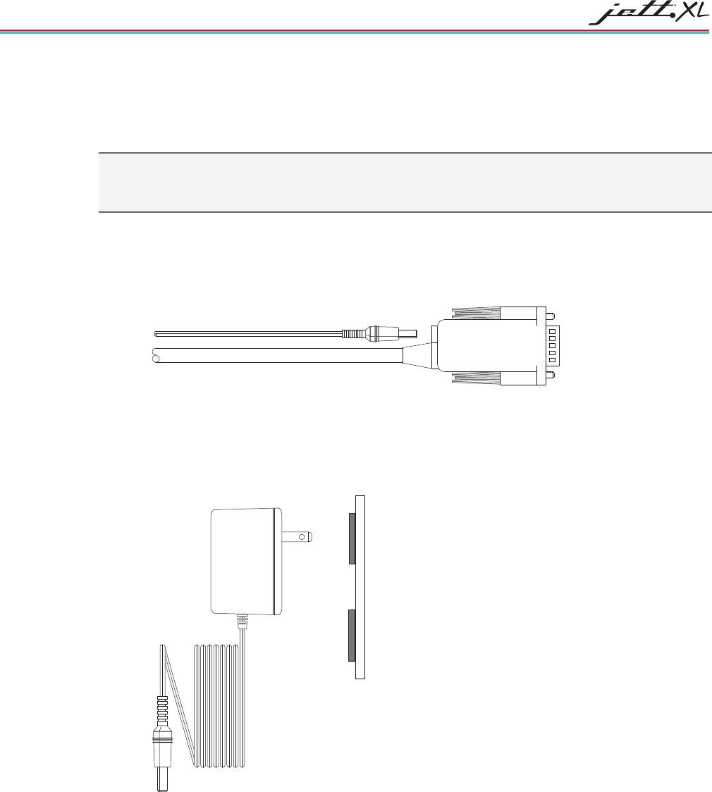
Figure 3-2: Using 91708/ 91709, and14375 Cables..................................................................................................154H3-3
Figure 3-3: Power Supply...........................................................................................................................................155H3-3
Figure 3-4: Changing Batteries .................................................................................................................................. 156H3-4
Figure 3-5: Standard 52-Key Keypad........................................................................................................................157H3-5
Figure 3-6: Standard 45-Key Keypad........................................................................................................................158H3-5
Figure 3-7: 45-Key Keypad Modifier Key ................................................................................................................159H3-6
Figure 3-8: Standard 30-Key Keypad........................................................................................................................160H3-7
Figure 3-9: Standard 15-Key Keypad........................................................................................................................161H3-7
Figure 3-10: CE Keyboard .......................................................................................................................................... 162H3-8
Figure 3-11: Transcriber.............................................................................................................................................. 163H3-8
Figure 3-12: Windows CE 5.0 Desktop .....................................................................................................................164H3-9
Figure 3-13: Windows CE 5.0 Desktop Taskbar ......................................................................................................165H3-9
Figure 3-14: Start Menu ............................................................................................................................................ 166H3-10
Figure 3-15: Using the Compact Flash Slot............................................................................................................ 167H3-13
Figure A-1: Case Dimensions ...................................................................................................................................168HA-2
Figure A-2: Case Dimension with JETT•HATCH .................................................................................................169HA-3
Figure B-1: 91708 Cable (Male DE9) RS-232 Signal and Pin Assignments...........................................................170HB-1
Figure B-2: 91709 Cable (Female DE9) RS-232 Signal and Pin Assignments.......................................................171HB-2


1-1
CHAPTER 1
OVERVIEW
ABOUT THIS MANUAL
This manual describes the standard features and operation of the JETT•XL. Unless otherwise stated, the
operational characteristics described herein correspond to factory default configurations and settings as
shipped from Two Technologies. Wherever used herein, the term “JETT” applies to all JETT•XL models
(except as noted).
It is beyond the scope of this manual to provide operating system tutorials or information about commercial
or customized JETT application programs and connected equipment. This information should be available
in the manuals that accompany those products.
RELATED DOCUMENTS
• JETT•XL Integration Guide
• JETT Wi-Fi Companion Users Guide
• JETT•XL/eye Bluetooth Users Guide
• JETT•pack Technical Reference Guide
• JETT•wave pack Integration Guide
• JETT•FUEL User’s Guide
• JETT Latching Mount User's Guide
• JETT•hangar Quad Cradle User's Guide
• JETT•hangar Single Cradle User's Guide
• Sync Commander User's Guide
ABOUT TWO TECHNOLOGIES
Two Technologies has been producing rugged hand held/panel mount terminals and computers since 1987.
By implementing state of the art design and manufacturing techniques, we revolutionized hand held
terminals and computers inside and out. Today, Two Technologies offers over a dozen cost-effective
solutions serving virtually every market worldwide.

OVERVIEW
1-2
ABOUT THE JETT•XL
With its modern, ergonomic appearance and design, the JETT•XL is the most recent addition to Two
Technologies' series of rugged hand held computers for industrial and commercial use. Its quick mount
connector system allows easy insertion and removal in cradle or vehicle mounts.
The JETT•XL comes standard with the Windows CE 5.0 operating system and an Intel PXA270 XScale
processor that operates up to 624 MHz. It also has configuration options for, Bluetooth, WLAN and serial
communication (RS-232, RS-485, RS-422 and USB). WWAN GSM/GPRS are also optionally available
When you add the JETT•PACK to the JETT•XL, you can integrate RFID, bar-code scanners, GPRS/GSM
devices, wireless radios and imagers.
JETT•XL FEATURES
OPERATING SYSTEM
The JETT•XL uses Windows CE 5.0 as its operating system. You can develop applications quickly and easily
using the latest development tools and network connectivity from Microsoft, such as eMbedded Visual C++
4.O, Visual Studio .NET 2003, Visual Studio 2005 and ActiveSync.
RECHARGEABLE BATTERY PACK
The JETT•XL comes with a rechargeable Nickel Metal Hydride (NiMH) battery pack that can provide up to
six hours of operating time on a full charge (depending on power management and use) .
The NiMH technology used in the JETT•XL has exceptional charge life without the “charge memory”
characteristic of conventional nickel cadmium batteries. Partially discharged batteries or extended periods
with the charger left connected will not adversely affect battery life or performance. The JETT•XL can also
run on six AA Alkaline batteries.
PROCESSOR
The JETT•XL utilizes an Intel PXA270 processor designed specifically for high-performance, low power,
portable, handheld devices. It incorporates Intel XScale technology with on-the-fly voltage, frequency
scaling and sophisticated power management. It also complies with the ARM Architecture V5TE instruction
set
MEMORY AND MASS STORAGE
The JETT•XL comes standard with 128MB of SDRAM (approximately 30MB used for the operating system)
and 512MB of internal compact flash memory. An additional 256 MB of SDRAM is optionally available.
Internal compact flash memory is optionally expandable to 8GB+.
For removable data storage or I/O cards, the JETT•XL is equipped with a Compact Flash (CF) slot.
DISPLAYS
The JETT•XL features a supertwist nematic liquid crystal 320 x 240 QVGA-TFT color sunlight readable
display with touch screen and LED backlight.
KEYPADS
Keypad configurations for the JETT•XL include 15-key, 30-key, 45-key and 52-key elastomeric keypads and
a 45-key membrane keypad. All standard keypad configurations have an option for LED backlighting.
INDICATORS
The JETT•XL has five programmable LED indicators that can provide a number of useful functions
including the state of keypad modifier keys. An additional LED indicates the charge and low battery
statuses.
OVERVIEW 1-3
CONFIGURATION OPTIONS
The JETT•XL comes standard with one JETT•connect serial port with choice of full RS-232 or a choice of
two of the following: short RS-232 (2), short RS-422, short RS-485 or USB. A modular serial port with a
choice of short RS-232, USB or Charge Jack is optionally available. The JETT•XL also includes configuration
options for USB (1.1), Wireless LAN (802.11b) and Bluetooth (1.1)
DURABILITY
The case is made of General Electric Xenoy, one of the most durable chemical resistant materials available
today.
INGRESS PROTECTION
The JETT•XL is completely dust-tight and can withstand exposure to jets of water and has an IP (Ingress
Protection) rating of 65 as defined by IEC standard 529.
Although not required to maintain an IP65 rating, Two Technologies offers connector covers that help
prevent electrolysis (corrosion that occurs due to a chemical reaction between water and a connector that
conducts electricity). For maximum protection, you should replace each plug every six months. Please note,
that the product warranty does not cover JETTs that fail due to electrolysis.
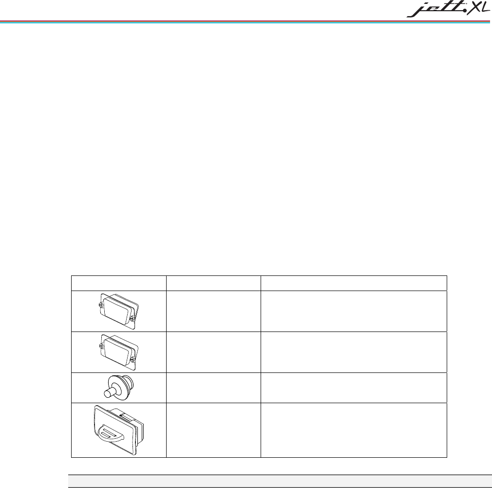
Table 1-1: Connector Covers
Illustration Part Number Description
14555 DE-9 Male Metal Plug
14556 DE-9 Female Metal Plug
14489 Power Plug
14492 JETT•connect Plug
Note: Illustrations are representative and not to scale.
2-1
CHAPTER 2
COMPONENTS AND INDICATORS
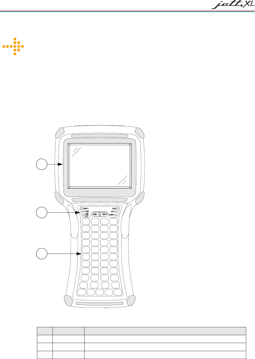
FRONT COMPONENTS
This section describes the components found on the font of the JETT.
Figure 2-1: Front Components
Table 2-1: Front Components and Indicators
Item Component Description
1 Display Supertwist nematic liquid crystal display with touch screen
2 Front Panel Contains the On/Off switch and modifier keys indicators (see Figure 2-2)
3 Keypad 45-key keypad shown (other keypads are also available, see Figure 3-9)
1
2
3
COMPONENTS AND INDICATORS
2-2
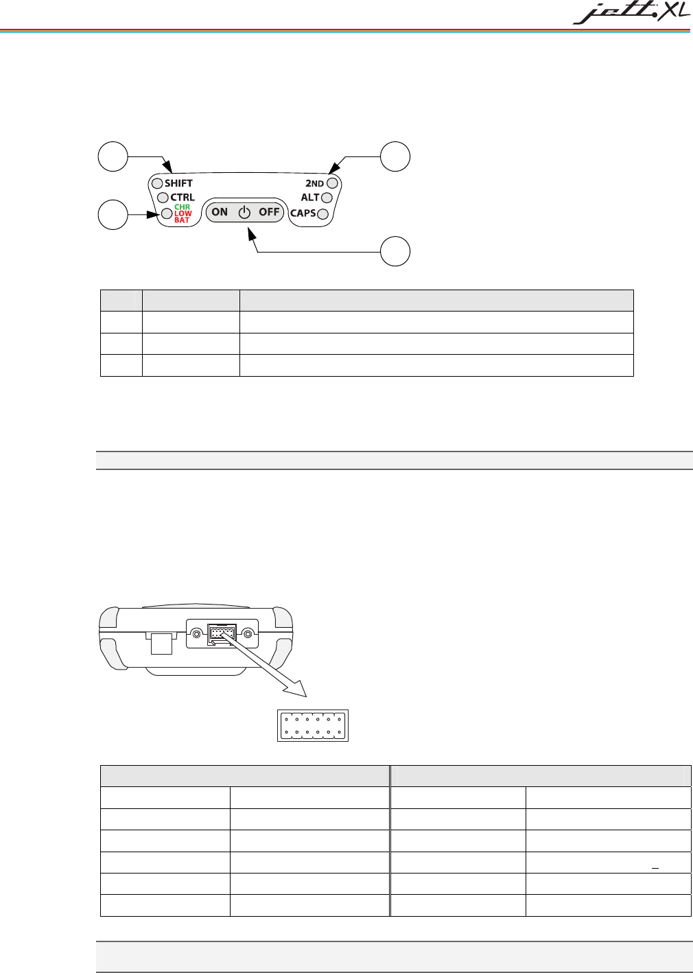
FRONT PANEL
This section describes the components found on the font panel.
Figure 2-2: Front Panel Components
Table 2-2: Front Components and Indicators
Item Component Description
1 Modifier LEDs Indicates use of the SHIFT, CTRL, 2ND ALT and CAPS modifier keys
2 Battery LED Lights red to indicate a low battery or green a charging battery
3 On/Off Switch Controls the Power, Suspend and Resume operations
INTERFACE CONNECTIONS
This section describes the interface connectors found on the bottom of the JETT.
Note: You can find Information regarding USB cables and connections in the JETT•XL USB supplement
JETT•CONNECT SYSTEM
The JETT•connect system is a set of rugged interface and cable connectors especially designed for industrial
environments. It features positive connector retention without any hardware restraints for quick
connect/disconnect operations and a contact design that prevents failure due to pin fatigue and cable stress
after repeated use.
Figure 2-3: JETT•connect Interface Connector
1
2
3
4
5
6
7
81012
911
Viewed facing connector
RS-232 Interface Pin-Outs with 11-18VDC Input RS-232 Interface Pin-Outs with 5VDC Output
Pin 1 = X1 Pin 7 = DSR Pin 1 = Tied to Pin 10 Pin 7 = DSR
Pin 2 = Ground Pin 8 = RTS Pin 2 = Tied to Pin 11 Pin 8 = RTS
Pin 3 = RI Pin 9 = DCD Pin 3 = RI Pin 9 = DCD
Pin 4 = CTS Pin 10 = 11-18VDC Input Pin 4 = CTS Pin 10 = 5VDC Output +10%
Pin 5 = DTR Pin 11 = Shield Pin 5 = DTR Pin 11 = Ground
Pin 6 = TXD Pin 12 = RXD Pin 6 = TXD Pin 12 = RXD
Note: Unless specified at time of order, the standard configuration for Pin 10 of the JETT•connect is 11-18VDC
Input
2
1
3
1
COMPONENTS AND INDICATORS 2-3
USING THE 5VDC OUTPUT LINE TO POWER EXTERNAL DEVICES
The JETT supplies only one +5 VDC line. The +5 volts supplied from the JETT•connect is the same line
supplied for JETT•pack integration. The +5 VDC line to the JETT•pack does not have the charging
protection components so output voltage will be higher by approximately 0.3V to 0.4V.
The following table shows the typical voltage versus current values when using the 5VDC output line to
power external devices
Table 2-3: 5VDC Typical Output Line Voltage versus Current Values
Load Current Voltage Out
50 Ohms 0.086 Amps 4.59 Volts
30 Ohms 0.14 Amps 4.54 Volts
25 Ohms 0.23 Amps 4.43 Volts
15 Ohms 0.3 Amps 4.37 Volts
12.5 Ohms 0.35 Amps 4.34 Volts
11 Ohms 0.4 Amps 4.29 Volts
8.5 Ohms 0.5 Amps 4.21 Volts
Note: Verify your intended use and current/draw with a properly configured JETT over your expected
environmental conditions prior to product deployment.
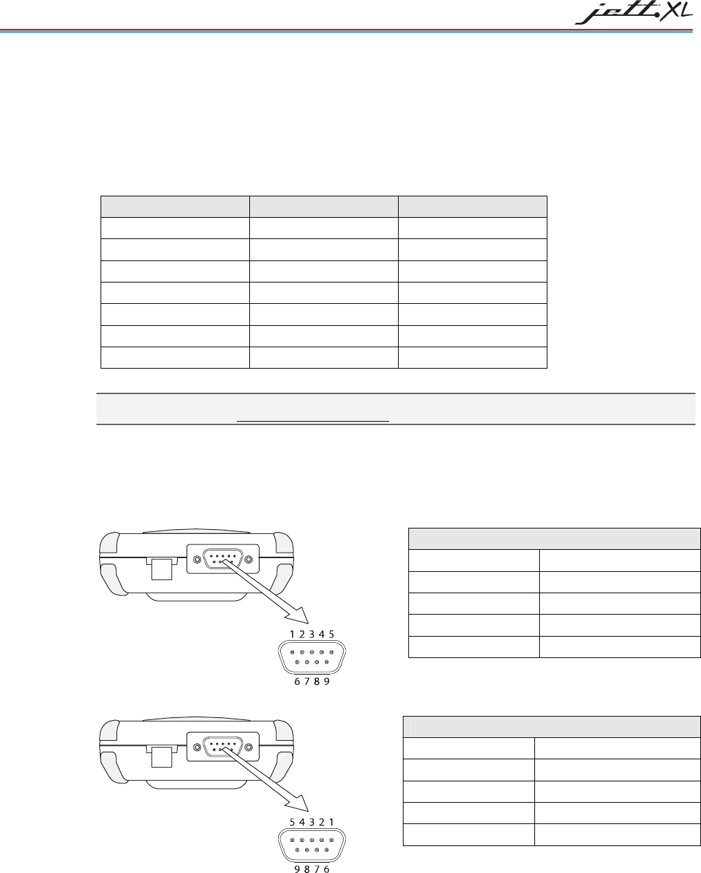
DE-9 CONNECTORS
The DE-9 connectors emulate standard serial pin-out connections, and allow you to connect the JETT to
most desktop PCs using a standard null modem cable.
Figure 2-4: DE-9 Male Interface Connector
Viewed facing connector
Figure 2-5: DE-9 Female Interface Connector
Viewed facing connector
RS-232 Interface Pin-Outs
Pin 1 = DCD Pin 6 = DSR
Pin 2 = RXD Pin 7 = RTS
Pin 3 = TXD Pin 8 = CTS
Pin 4 = DTR Pin 9 = 11-18VDC Input
Pin 5 = Ground
RS-232 Interface Pin-Outs
Pin 1 = DTR Pin 6 = DTR
Pin 2 = TXD Pin 7 = CTS
Pin 3 = RXD Pin 8 = RTS
Pin 4 = DSR/DCD Pin 9 = 11-18VDC Input
Pin 5 = Ground
COMPONENTS AND INDICATORS
2-4
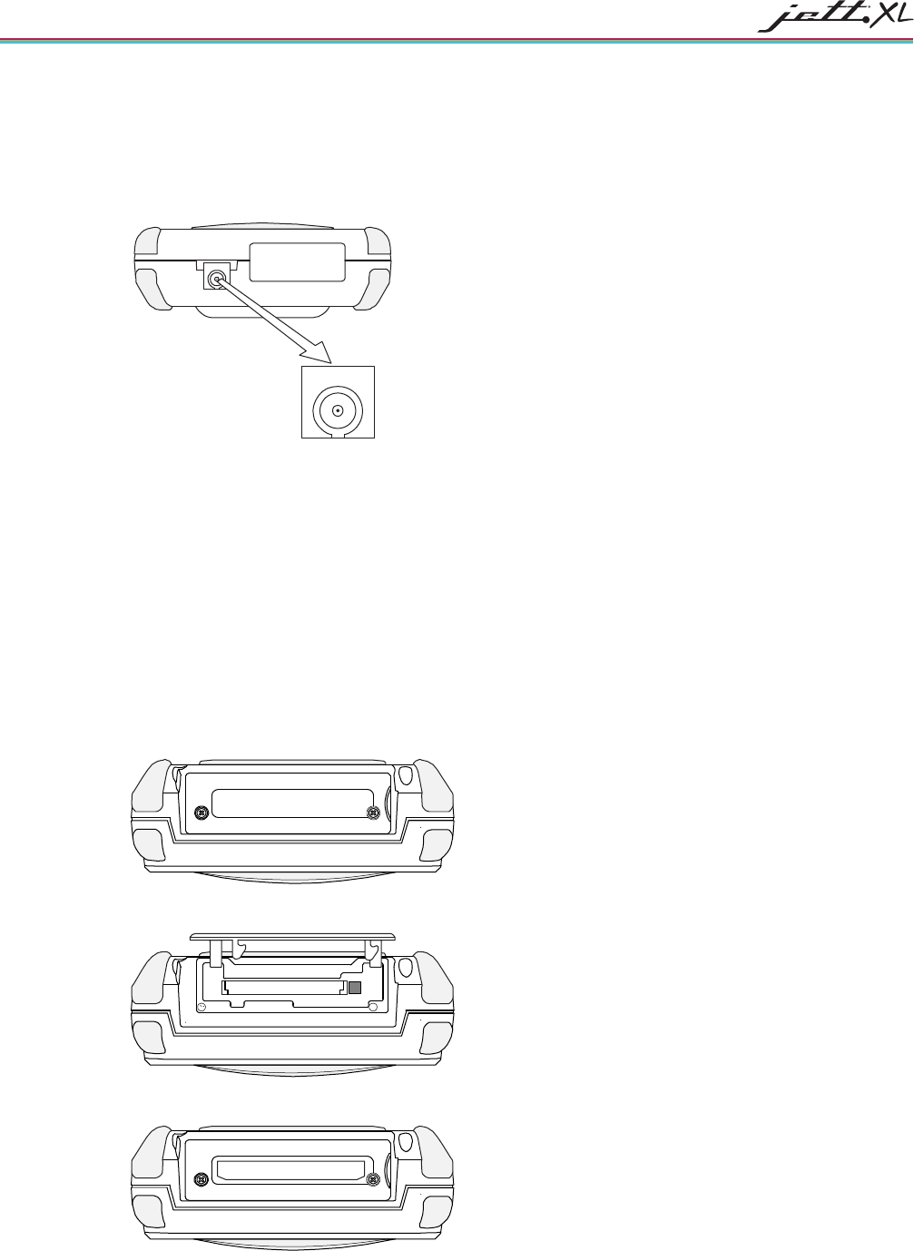
POWER JACK
The optional power jack found on the bottom of the JETT enables you to connect an 11-18 VDC Input power
supply battery charger, such as Two Technologies #14508. Use of other power supplies unless approved by
Two Technologies may cause damage to the unit and void the warranty.
Figure 2-6: Power Jack
Viewed facing connector
COMPACT FLASH SLOT COVER
The standard compact flash slot cover located on the top of the unit provides access to the compact flash slot
that stores memory and device cards. In addition to the standard cover, a modified cover which has a
machined opening that allows you to easily insert and remove devices cards that exceed 1.437 inches in
height, is also available.
Two phillips-head screws+ (2-56 x 5/16”) secure the cover to the top of the JETT. To insert device or
memory cards into the compact flash slot, you must first remove these screws using a phillips # 0 non-
magnetic tip screwdriver, which you can purchase from Two Technologies (Part Number 14673). You can
also purchase additional screws from Two Technologies (Part Number 12624).
For information about inserting and removing memory and device cards, see Using the Compact Flash Slot.
Figure 2-7: Standard Compact Flash Slot Cover, Closed
Figure 2-8: Standard Compact Flash Slot Cover, Opened
Figure 2-9: Modified Compact Flash Slot Cover for Long Device Cards
COMPONENTS AND INDICATORS 2-5
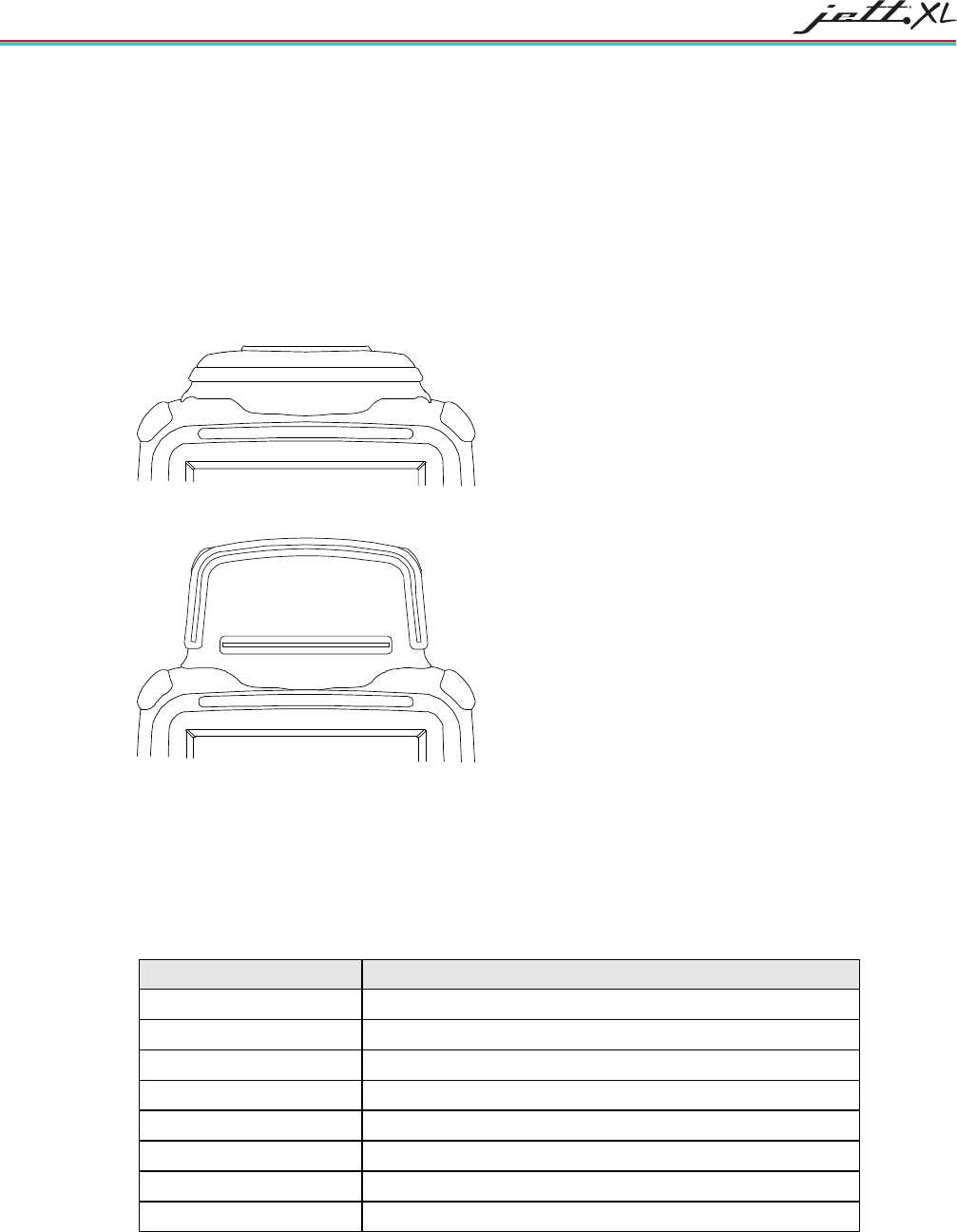
THE JETT•HATCH
By using the JETT•HATCH (available at time of order), you can thoroughly seal the JETT and maintain a
total IP65 solution when using CF-based peripherals installed in the User CF slot . The JETT•HATCH comes
in two sizes (see Figure A-2 for dimensions):
• Low Profile—accommodates standard CF-based peripherals, such as WLAN and Bluetooth CF
cards
• High Profile—accommodates larger CF-based peripherals, such as GPS, and GPRS CF cards
Figure 2-10: Low Profile JETT•HATCH
Figure 2-11: High Profile JETT•HATCH
POWER SUPPLIES, CABLES AND ADAPTERS
Two Technologies can provide the following optional power supplies, cable and adapters based on
communication and power requirements. For cable signal and pin assignments, see Appendix B: Signal and
Pin Assignments.
Table 2-4: Available Power Supplies, Cables and Adapters
Two Technologies Part # Part Description
14508 11–18VDC Power Supply (North America Only) 1
91708 Black, 15-Foot JETT•connect Cable (DE-9 Male)
91709 Black, 15-Foot JETT•connect Cable (DE-9 Female)
14375 Black, 15-Foot Null Modem Cable (DE9 Female to DE9 Female)
14987 USB Cable, Type A to Mini B
14988 USB Cable, Mini A to Type B
14989 USB Cable, Mini A to Mini B
15094 USB Cable, Mini A to Type A (Female)
1. Use of other power supplies unless approved by Two Technologies may cause damage to the unit and void the warranty.
3-1
CHAPTER 3
OPERATION
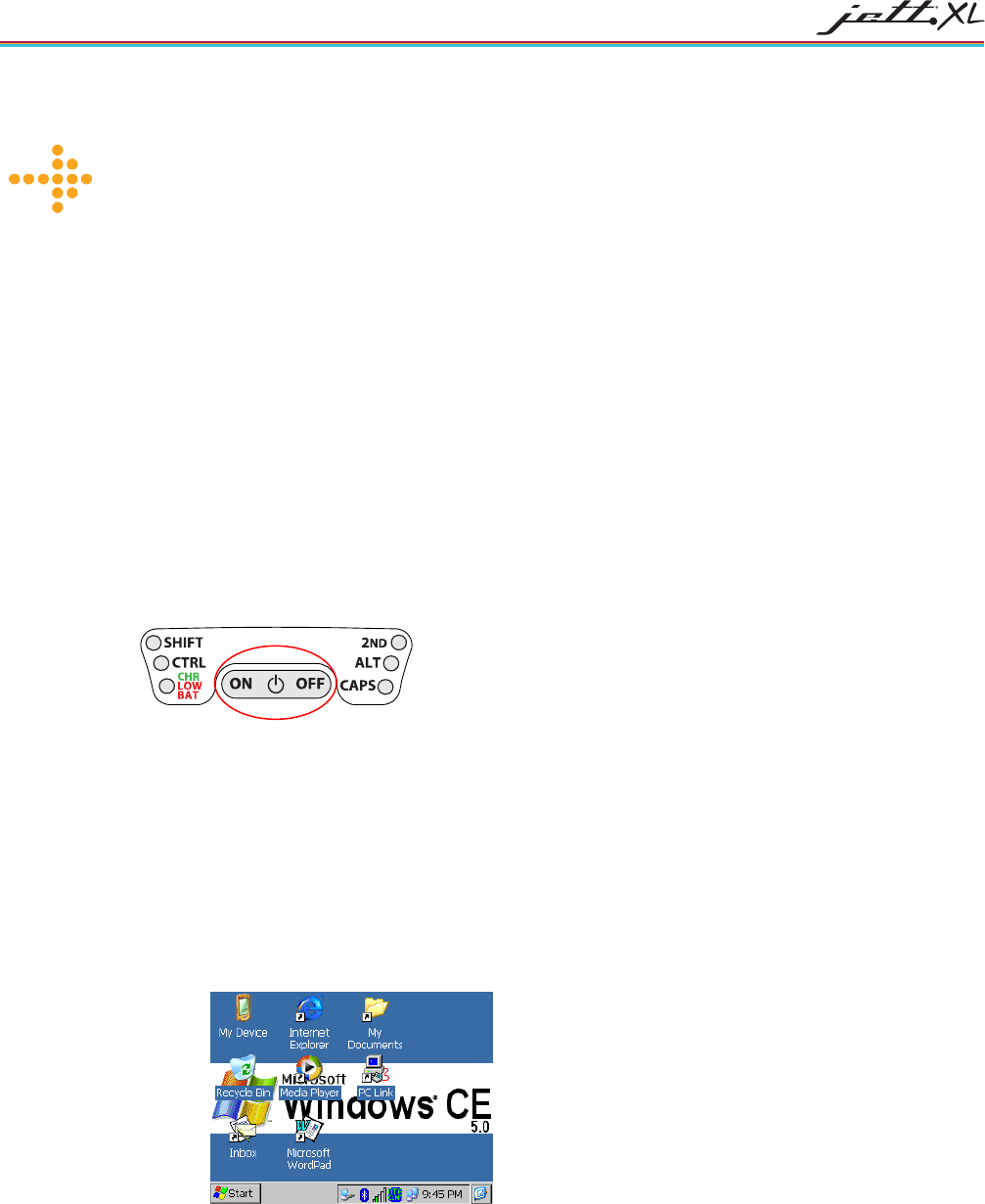
THE POWER/SUSPEND SWITCH
The On/Off switch is located above the keypad. Its function depends on the state of the JETT at the time the
switch is pressed and on the length of time that the switch is depressed. Operations that the On/Off switch
can initiate are:
• Power On
• Power Off
• Suspend
Figure 3-1: On/Off Switch
POWER ON
To power on the JETT:
1. Press and hold the On/Off switch for one second. The unit should turn on and begin displaying
the boot-up process. For example:
Where x.x.x is the version number
2. After approximately 15 seconds, the Windows CE 5.0 desktop should appear. If the unit does not
power up or you cannot select any items from the desktop, refer to the “Troubleshooting” chapter
for help.
POWER OFF
To turn off the JETT, press and hold the On/Off switch for approximately eight seconds. This action will
also terminate running applications and cease serial port operations).

OPERATION
3-2
SUSPEND MODE
Suspend mode allows you to suspend, but not terminate active applications. In this mode, the display will
turn off and the JETT will cease serial port operations. For battery-powered units, Suspend mode also
conserves battery power. To place the unit in Suspend mode, press and release the On/Off switch. To take
the JETT out of Suspend mode, press and release the On/Off switch again. The display will turn on and the
JETT will resume running any suspended application, but you must restart any serial port operations. If you
attempt to resume immediately after suspending the JETT or vice versa, the unit will delay three seconds
before resuming or suspending.
USING THE RECHARGEABLE BATTERY
The JETT•ce comes with a rechargeable Nickel Metal Hydride (NiMH) battery pack that can provide up to
six hours of operating time on a full charge (depending on power management settings and peripheral use).
You will need to charge the Nickel Metal Hydride rechargeable battery pack a minimum of three hours
prior to first use. Please note that the battery pack will not attain maximum capacity until it has been
charged and discharged approximately four times. As a result, you may experience shorter than expected
operating time on the first few uses of the product.
NiMH batteries are an extremely stable and dependable source of electrical energy, but can be
sensitive to extreme temperature. If you charge the battery pack in extreme hot or cold, it will not
attain a full charge, and as a result will exhibit decreased useable time until it recharging again.
As a precaution against overheating, the JETT has built-in temperature sensors that will suspend
the charging process if the battery becomes too warm.
Because the battery pack is an electrical device, you should not expose it to moisture or wet
environments. If the battery becomes wet, wipe it dry and then allow it to dry thoroughly for
several hours before attempting to use or charge it.
Do not leave the battery pack in a fully discharged state for extended periods. This condition may cause one
or more of the cells within the battery pack to fail. When this occurs and the battery pack is subsequently re-
charged, the failed cell will reduce the total voltage capacity of the battery pack, thus making the battery
appear to discharge faster.
CHARGE/LOW BATTERY INDICATOR
When using the NiMH battery pack, the CHARGE/LOW BAT LED will indicate the current battery status
as shown in the table below.
Table 3-1: Charge\Low Battery Indicator Functions
Function Description
CHARGE With the power supply connected, the CHARGE/LOW BAT LED will indicate one of
following conditions:
High Power Charge—the LED will turn solid green until the battery reaches
80% capacity of its charge capacity
Trickle Charge—the LED will blink green about four times a second when the
battery reaches 80% capacity of its charge capacity
LOW BAT With the power supply disconnected, the CHARGE/LOW BAT LED will indicate one
of following conditions:
Batteries are low—the LED will blink red once per second when there is
approximately 30 minutes of power remaining
Batteries are very low—the LED will turn solid red when there is
approximately 10 minutes of power is remaining
OPERATION 3-3
CHARGING THE UNIT
The nickel metal hydride battery technology used in the JETT has exceptional charge life without the
“charge memory” characteristic of conventional nickel cadmium batteries. Partially discharged batteries or
extended periods with the charger left connected will not adversely affect battery life or performance.
Note: Because the internal battery charger senses several conditions, including temperature, you should
charge the unit away from any known or potential heat sources. Units exposed to temperatures in excess of 110
degrees Fahrenheit during the charge cycle may experience incomplete charging and reduced operating
time per charge.
To charge the NiMH battery pack:
1. Depending on your configuration, plug the power jack of the battery charger/power supply into
the corresponding cables connector and/or adaptors as shown below.
Figure 3-2: Using 91708/ 91709, and14375 Cables
Power Supply/Battery Charger
To Unit
2. Plug the interface cable into the connector on the bottom of the JETT. If your unit has a power jack
receptacle on the bottom of your JETT, just plug the power jack into that receptacle.
3. Plug the battery charger/power supply into a power outlet. The Charge LED should turn on,
indicating that the batteries are charging (see Table 3-1).
Figure 3-3: Power Supply
4. Once the battery is fully charged (approximately four hours), you can disconnect the AC power
supply and run the JETT exclusively on battery power.
OPERATION
3-4
REPLACING BATTERIES/BATTERY PACK
CAUTION! There is a risk of explosion if you replace the NiMH battery with an incorrect type. Only use a NiMH
battery supplied with your unit or a replacement NiMH battery supplied, recommended, or approved by Two
Technologies, Inc.
When using alkaline batteries, replace all alkaline batteries in the JETT at the same time. Do not mix old and
new batteries, mix different types or brands of batteries, or dispose of the batteries in a fire. These actions
can cause battery rupture or leakage that result in personal injury or property damage.
Remove the batteries from the JETT when not using the JETT for extended periods. Store the batteries in a
cool, dry location at normal room temperature.
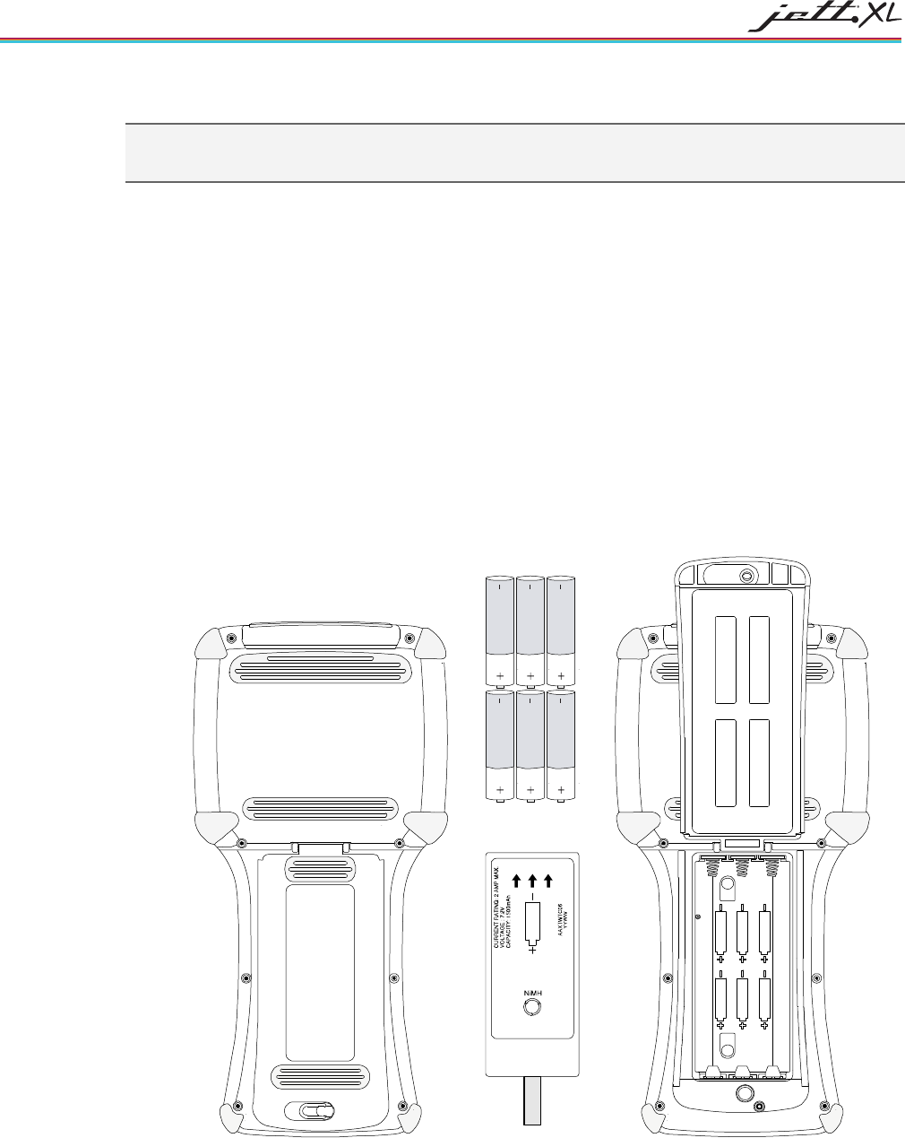
To replace the rechargeable battery pack or change AA batteries:
1. Turn the power off. With the unit face down, pull the battery cover retaining clip up from its
recessed slot and turn the clip in a counter clockwise motion (see Figure 3-5).
2. Lift the cover up and remove the batteries/battery pack.
3. If the unit contains a NIMH battery pack, use the tab to lift up on the battery pack and then out.
4. Close the battery cover and turn the battery cover retaining clip clockwise to lock the cover.
Figure 3-4: Changing Batteries
TOP
PLEASE RECYCLE
BOTTOM
CAUTION:
RISK OF EXPLOSION IF BATTERY
IS REPLACED BY AN INCORRECT
TYPE. DISPOSE OF USED BATTERIES
ACCORDING TO THE INSTRUCTIONS.
Battery Pack Cover
(opened)
NiMH
Battery Pack
Tab
Akaline Batteries
Battery Pack Cover
(closed)
Retaining Clip
OPERATION 3-5
DATA ENTRY
KEYPADS
52-KEY KEYPADS
This joystick style keypad with bezel nomenclature features easy screen navigation and alphanumeric
keypad entry and four programmable function keys. Users can also access navigation keys and backlight
control via the SHIFT key.
Figure 3-5: Standard 52-Key Keypad
DELETE
INSERT CAPS LK HOME
PG UP PG DN PAUSECLEAR SCRL LK
\/
ALTTAB TAB
WMENU #BKLT+ BKLT- ,
BK SP SPACE
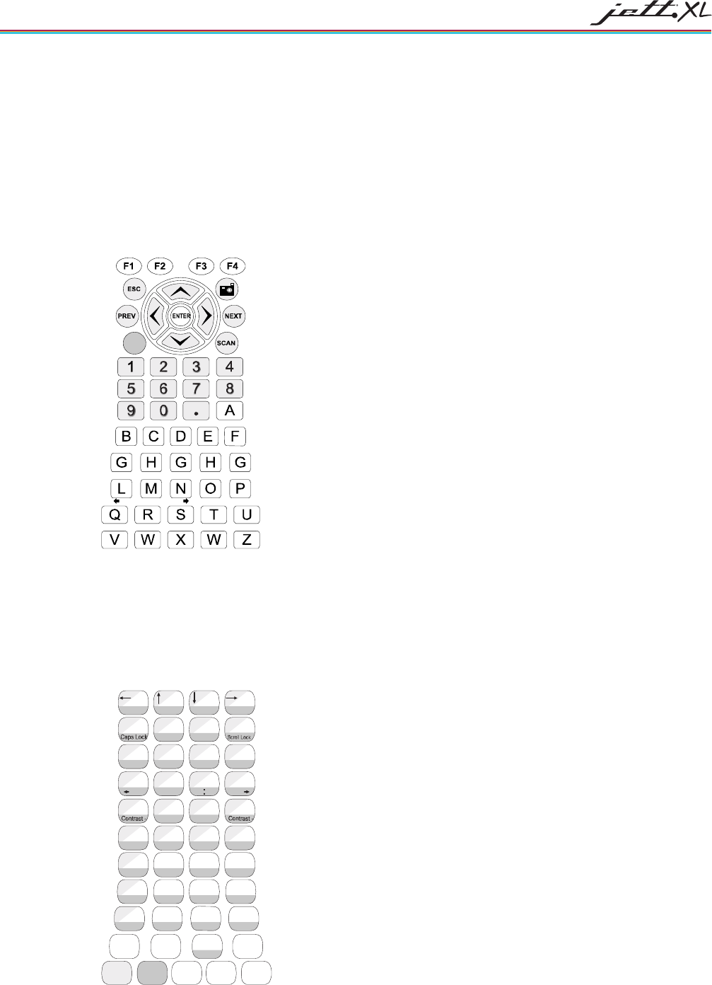
45-KEY KEYPADS
In order to provide the functionality of a full-sized keyboard with only 45 keys, the JETT keypad makes use
of modifier keys. Units configured with the standard 45-key keypad typically utilize five LED indicators
(located above the On/Off switch) to indicate the active state of keypad modifier keys. Units with 45-key
keypads also have keypad functions to adjust the contrast and backlight.
Figure 3-6: Standard 45-Key Keypad
G
A
Delete B
PgUp C
PgDn D
Insert
E F
Home H
I
{J
~
KL
}
<END _>
^
Pause
(!;)
[?']
RST
#
Q
&@$
U
+V
,
/X
BKLT +
-
W
=
Y
%7
F7 9
F9
8
F8
Z
*4
F4
6
F6
5
F5
.
\1
F1
2
F2
3
F3
0
F10
BACK
SPACE SPACE ENTER
SHIFT 2ND CTRL ALT ESC
BKLT -
"
Clear
OMN P
Tab Tab
,
WMENU
F11
F12
|
OPERATION
3-6
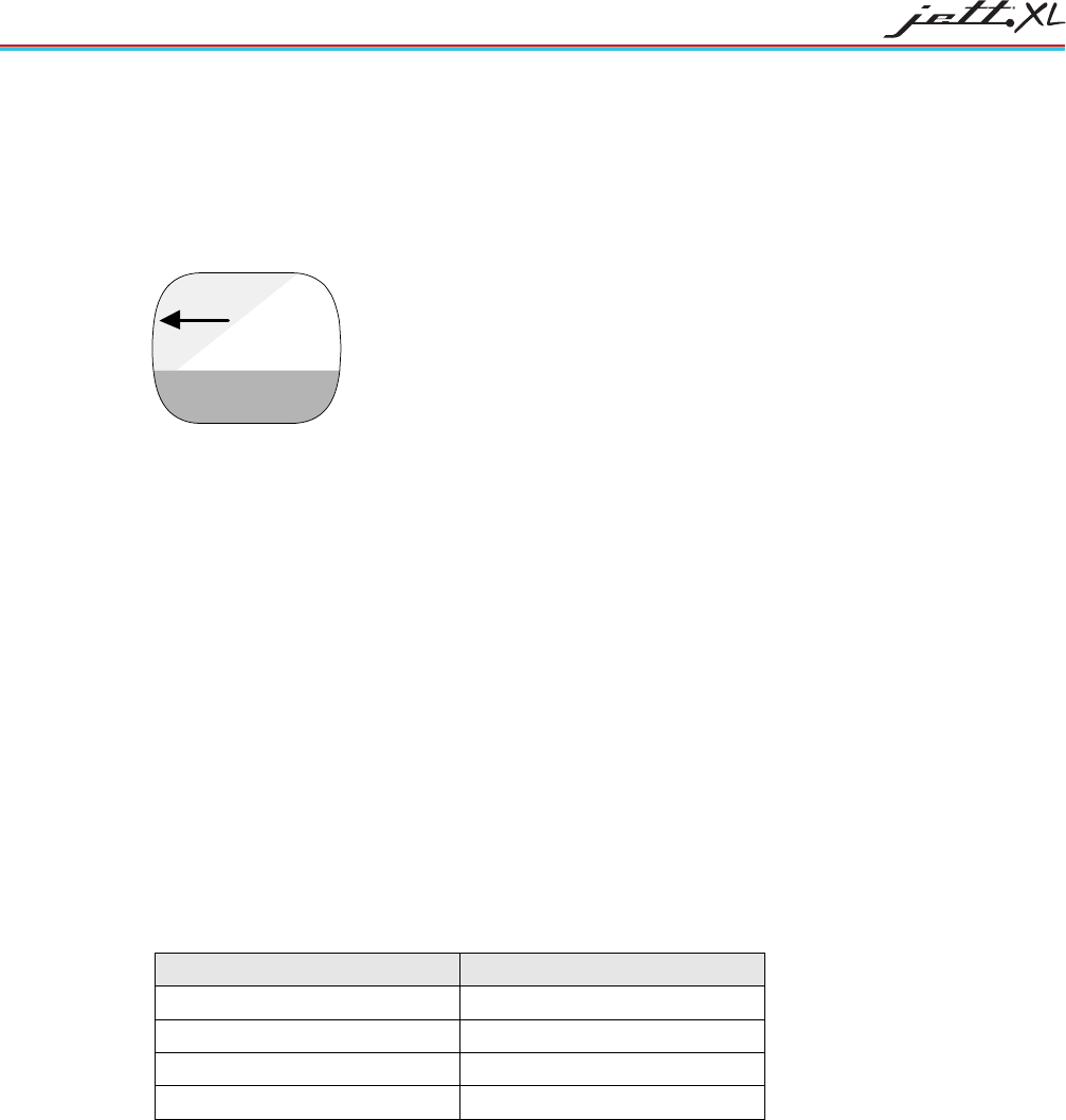
45-KEY KEYPAD MODIFIER KEYS
The following modifier keys (located on the bottom of a standard keypad) enable you to access the various
functions that can appear on a key. Modifier keys take effect when first pressed and typically remain in
effect until you press another key, unless its another modifier key (see Table 3-2). Optionally equipped units
can use LEDs to indicate the selection of a modifier key. Figure 3-8 provides examples.
Figure 3-7: 45-Key Keypad Modifier Key
A
Delete
• CTRL and ALT Keys—operate in the same manner as on conventional PCs, except that by default
they have a one-time locking action to facilitate one-handed operation.
SHIFT Key—unlike conventional PC keyboards, the SHIFT key enables you to access symbols,
punctuation marks and navigation arrows rather than shift alphabetic keys to uppercase. By
default, the SHIFT key has a one-time action. However, you can press the Shift key twice and lock
the keypad into Shift mode, wear each subsequent key press will only access characters that appear
in the upper left of a key. Pressing the Shift key a third time will release Shift mode.
On standard JETT 45-key keypads, the functions and characters accessed via the SHIFT key appear
in the upper left of a key (shaded in light gray in Figure 3-8).
5. 2ND Key— shifts the numeric keys to corresponding function keys (1 = F1, 2 =F2, etc.) that are
found on conventional PC keyboards. It also shifts other keys for punctuation, non-printing
characters (such as Delete and TAB), and PC key definitions (such as Page Up, Page Down, Home,
Insert and Caps Lock).
On standard JETT 45-key keypads, the functions and characters accessed via the 2nd key appear at
the bottom of a key, (shaded in dark gray in Figure 3-8).
Like the Shift key, the 2ND key has a default one-time action and a locking mode (i.e., pressing
the 2ND key twice will lock the keypad into 2ND mode).
Table 3-2: Modifier Key Actions
Key Presses Result
A Lowercase “a”
Shift & A Move cursor left one position
2ND & A Delete Character
2ND & Caps Lock Uppercase “A”
OPERATION 3-7
30-KEY KEYPAD
Units with a 30-key keypad provide a full complement of alphabetical characters. Users can access numeric
characters, punctuation characters, navigation keys and backlight control via the SHIFT key.
Figure 3-8: Standard 30-Key Keypad
SHIFT
ALT ESC
0
BACK
SPC SPC ENTER
798
*
465
123
U
+
V
,
/
X
BKLT
+
-
W
BKLT
-
Z
Y
G
ABC
DEF
HI
JKL
?
R
ST
Q
OMN
P
TAB
:
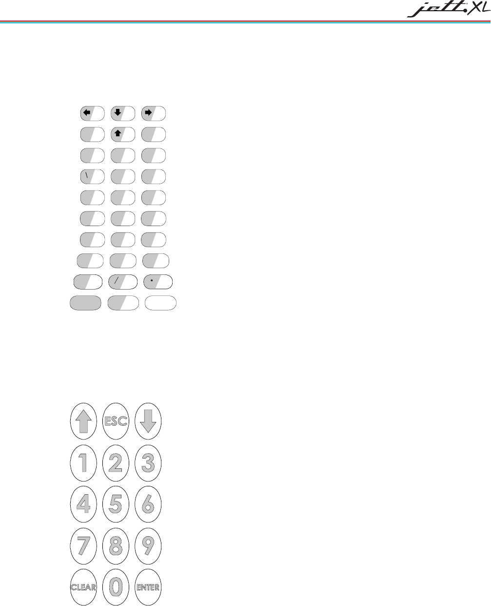
15-KEY KEYPAD
Typically, units shipped with a 15-key keypad have custom keyboard layouts geared toward specific
applications that must be loaded onto the unit. To provide you a method of navigating and using Windows
CE 5.0 until you configure and map your keypad for your application, Two Technologies provides a
template that shows how to access the default functions (see figure below).
Figure 3-9: Standard 15-Key Keypad
KEY REPEAT
By default, the JETT does not automatically repeat a key stroke when you hold down a key. However, you
can enable the key repeat function by configuring the Keyboard setting in the Control Panel.
OPERATION
3-8
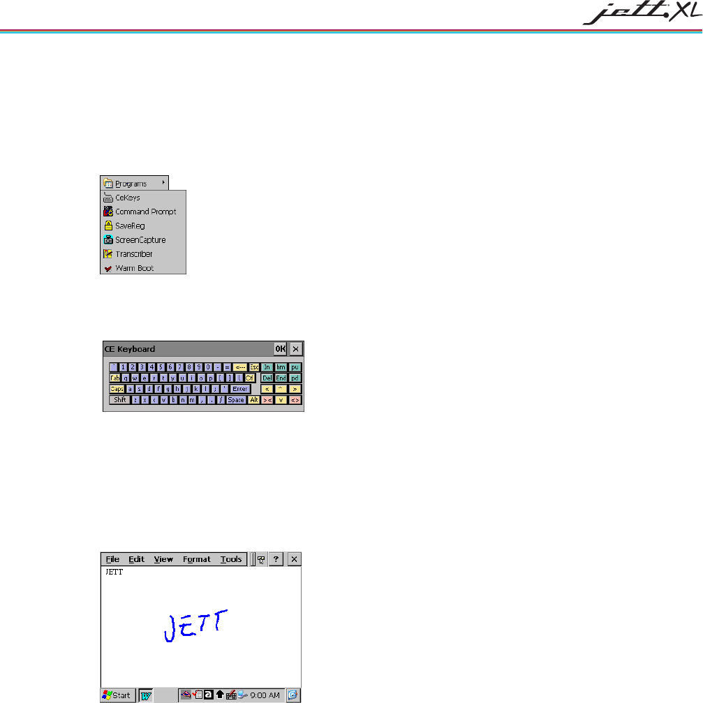
CE KEYBOARD
In addition to entering data through the keypad, you can also enter data by using the CE Keyboard. This
utility displays a keyboard on the screen to allow data entry via the Command Line or into applications
where “text accessibility” control has focus (i.e., text or combo box).
To use the CE Keyboard, select Programs > Tools> CeKeys from the Start menu.
To minimize the keyboard, click the keyboard icon that appears in the system tray
Figure 3-10: CE Keyboard
TRANSCRIBER
Microsoft Transcriber is a natural handwriting recognition software program that interprets pen movement
across the screen as handwriting (cursive, print or mixed) input. For more information, please refer to
Microsoft Transcriber Help on the JETT.
To run Microsoft Transcriber, select Programs > Tools> Transcriber from the Start menu.
Figure 3-11: Transcriber
OPERATION 3-9
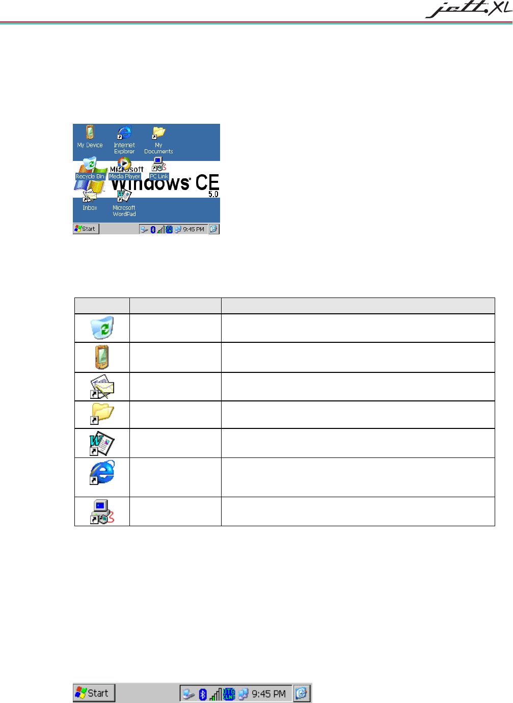
THE WINDOWS CE 5.0 DESKTOP
This section provides a brief overview of the functions that appear on the Windows CE 5.0 desktop. For
information on how to change desktop settings, refer to Windows CE help (Start > Help).
Figure 3-12: Windows CE 5.0 Desktop
WINDOWS CE 5.0 DESKTOP FUNCTIONS
You can access the following applications, functions and utilities from the Windows CE 5.0desktop:
Table 3-3: Windows CE 5.0 Desktop Functions
Icon Function Description
Recycle Bin Use the Recycle Bin to restore deleted files or empty the bin to
create more disk space.
My Device Use My Computer to navigate and view the folders and files
stored on the JETT.
Inbox Use the Inbox to send and receive e-mail by connecting to a
POP3 or IMAP4 server.
My Documents The default storage location for documents, graphics, and other
files.
Microsoft WordPad
Use WordPad to create or edit text files that contain formatting
or graphics.
Internet Explorer Use Internet Explorer to view Web pages. You will need a
modem or Ethernet card to connect to an Internet service
provider (ISP) or network.
PC Link Use PC Link to make an ActiveSync, Bluetooth or other type of
connection to another device
THE TASKBAR
The taskbar at the bottom of the JETT desktop displays the Start button, buttons of currently running
applications, the Status Area and the Show Desktop icon.
Tap the Start button to display the Start menu (see below for details). For each open application, a button
appears on the taskbar. Simply tap the button to activate the application.
The status area appears on the right and by default displays small icons for the input panel, current time,
power status and network connections. Tap an icon to activate the related program.
Tapping the Show Desktop icon minimizes active applications and redisplays the desktop. Tapping the
Keyboard icon displays the Input Panel menu for data entry.
Figure 3-13: Windows CE 5.0 Desktop Taskbar
OPERATION
3-10
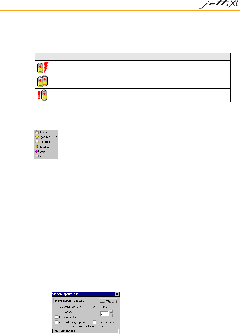
POWER STATUS ICONS
The JETT will display power status icons (Table 3-4) in the taskbar status area (Figure 3-14) to indicate
power use, charging status and low battery conditions.
Table 3-4: Power Status Icons
Icon Description
Batteries are charging
Batteries are low—approximately 30 minutes or less of use remaining (the
CHARGE/LOW BAT LED will blink red once per second)
Batteries are very low—approximately 10 minutes or less of use remaining (the
CHARGE/LOW BAT LED will turn solid red)
THE START MENU
When you tap Start, the Start menu appears.
Figure 3-14: Start Menu
By tapping one of the menu’s icons (and not the name), you can:
• Open programs that do not appear on the desktop
• View a list of web sites added to your Favorites List
• View recently accessed documents and images
• Access the Control Panel, establish connections, or configure the Taskbar and Start Menu
• View Help
• Start an application using the Run command
MISCELLANEOUS TOOLS
You can access the following utility programs from the Tools menu.
SCREEN CAPTURE
The Screen Capture program takes a picture of the screen and saves it as a bitmap file (.BMP) to a
designated location. You can set up the program to run from the system tray, or by pressing a hot key.
To setup the Screen Capture program:
1. From the Start menu, select Programs > Tools > Screen Capture. The ScreenCapture.exe dialog box
appears:
OPERATION 3-11
By default, the Screen Capture program is set to take a picture by pressing HotKey1 after a five-
second delay.
2. To change the wait time before the Screen Capture program takes a picture, tapping the up or
down scroll bars under Capture Delay (sec). The default value is five seconds.
3. To change the Keyboard Hot Key assignment, you must access the Hot Key applet in the Control
Panel. The default value is five HotKey1
4. To have the Screen Capture program take a picture when you tap its icon in the System Tray, check
Auto run in the task bar.
Note: To deselect this option after making it active, tap and hold the icon until the Screen Capture
program appears.
5. To view the picture immediately following the screen capture, check View following capture.
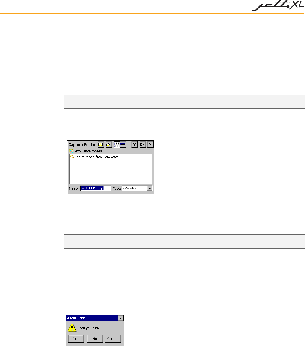
6. To change the default folder (My Document) where picture are stored, tap the button under Store
screen capture in folder.
7. Select a new location and tap OK.
8. By default the Screen Capture program, automatically assigns a number to each screen capture.
The numbering scheme starts at JET00000 and increment by one after each capture. To set this
number back to JET00000, check Reset the counter.
Note: Screen captures stored in folders other than the SystemCF folder will be lost if you remove power
from the unit.
WARM BOOT
Occasionally, a program may encounter an error from which it cannot recover. In these cases, you
can perform a warm boot, which will reinitialize the unit without affecting the contents store in
virtual memory.
To perform a warm boot:
1. Select Programs > Tools> Warm Boot. The “Are you sure” prompt appears.
2. Tap Yes to warm boot the unit.

OPERATION
3-12
MANUALLY SAVING THE PERSISTENT REGISTRY
The JETT internal memory consists of DRAM and Flash. Typically, any changes made to the JETT including
file creation are temporarily stored in the unit’s DRAM. You must then copy the files from DRAM to
internal flash memory or a removable compact flash card to store the information permanently.
Consequently, if you do not store the information to flash memory and the unit loses power, all information
stored in DRAM will be lost. However, whenever you make changes that affect the registry, such and
changing settings in the Control Panel or installing software, you can permanently store registry changes
without writing to flash memory by using the Persistent Registry.
Note: The JETT will also store registry information every time you perform a suspend/resume operation.
To store registry information on the JETT permanently:
1. From the Start menu, select Programs > Tools> SaveReg.
2. The JETT will begin saving the registry.
3. After you successfully save the registry, a message box will appear:
4. Tap OK to close the message box.
COMMAND PROMPT WINDOWS
The command prompt window allows you to execute limited MS-DOS command line arguments (e.g., CD
SystemCF, Run TEST.BAT, etc.).
To open the Command Prompt window:
1. From the Start menu, select Programs > Tools> Command Prompt. The Command Prompt
window opens:
2. You can then type in your commands. For a list of supported commands, type Help and press
Enter.
3. To end the session, type Exit and press Enter.
SYSTEMCF FOLDER
The only folder that provides non-volatile (permanent) storage is the SystemCF folder. Information stored in
other folders will be lost when you remove power from the JETT. You can however, have the JETT
automatically copy files from the SystemCF to other folders when booting up.
OPERATION 3-13
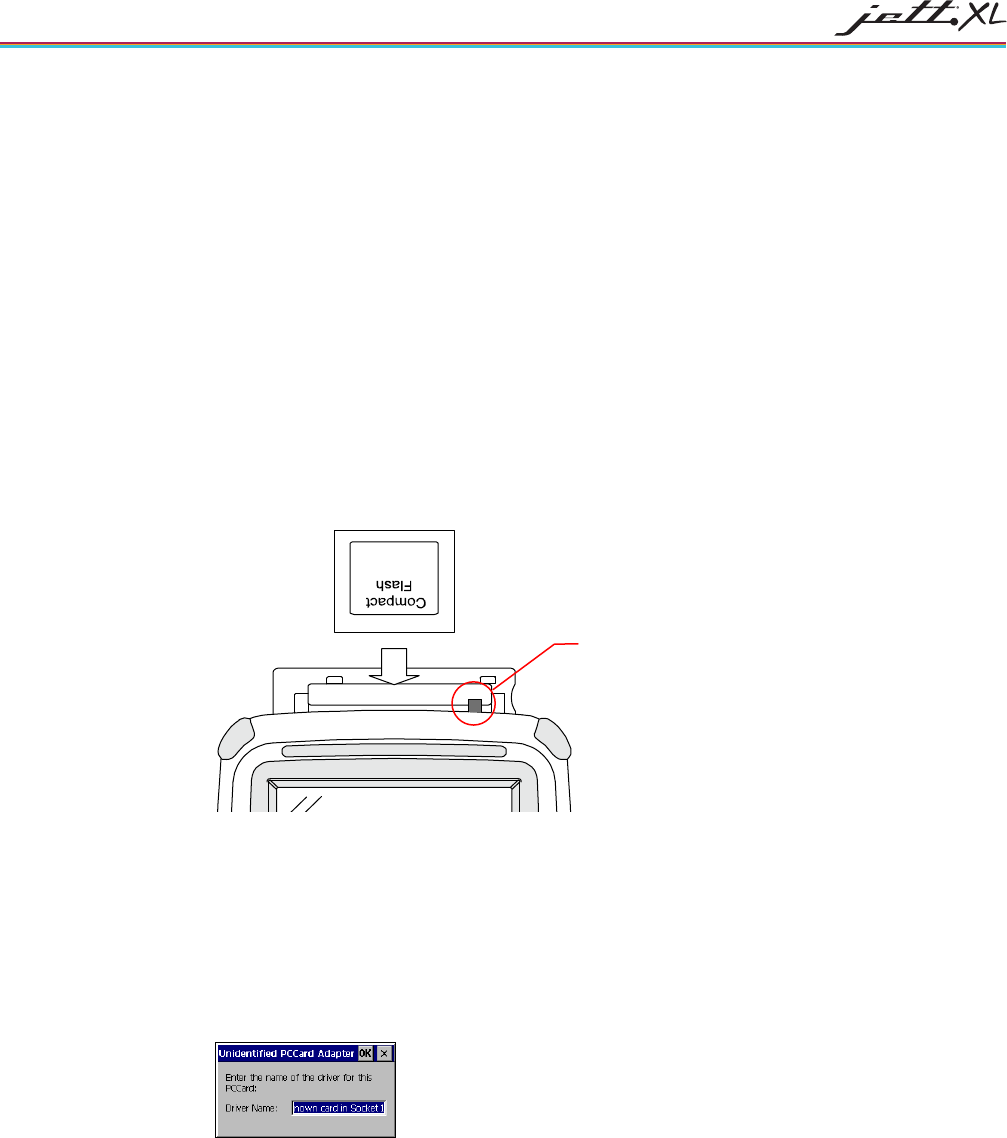
USING THE COMPACT FLASH SLOT
The Compact Flash Slot located on top of the JETT enables you utilize a variety of devices such as memory
cards, barcode scanners, GPS cards and network cards.
If you intend to use a device card, it may also be necessary to install a driver. If so, make sure the card is
Windows CE 5.0 compatible and you have the necessary drivers. If you are not sure, check with the card
manufacturer before attempting to install the card.
To use the compact flash slot:
1. If needed, remove any screws from the cover to access the Compact Flash slot. Refer to the
“T6Compact Flash Slot Cover” section for information about cover and screw types.
2. With the front of the display facing you, push the compact flash slot cover to the left. The slot cover
will automatically pop open. If the cover has a slot, you can skip this step.
3. Insert the compact flash/device card into the slot with the front of the display facing you and the
top of the card pointed to the slot until it clicks and the release lever moves upward.
Figure 3-15: Using the Compact Flash Slot
4. Close the cover.
5. When inserting memory cards, a “UserCF” folder will appear when you open My Computer. You
can then copy and paste the contents of UserCF to the other folders on the JETT.
6. When inserting device cards, the JETT will attempt to recognize the device. If it finds a driver for
the device, the JETT will display a dialog box for that device. For example:
Error! Objects cannot be created from editing field codes.
7. If the JETT cannot find a driver for the device, it will display the following dialog box:
8. If the correct card type appears, you can enter the appropriate information in the dialog box and
then tap OK to complete the installation.
9. To remove a card from a slot, simply push the card release lever down and remove the card.
Release Lever
4-1
CHAPTER 4
CONFIGURATION
THE CONTROL PANEL
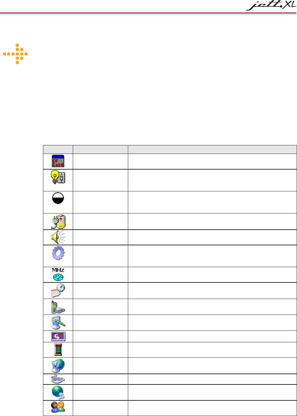
The table below lists the available control panel functions on the JETT.
Table 4-1: Control Panel Functions
Icon Function Description
Aux CF Card This function enables you to enable/disable power to CF cards
installed in the internal CF Card slot, which not user accessible.
Aux Switch For units with a second COM that supplies 5VDC output, use this
function to set the default power state (On or Off), and test the
connected devices.
Backlight Use this function to adjust the backlight setting for the following
conditions: Line Active, Line Active Inactive, Battery Active and
Battery Inactive.
Battery Select Select one of the following options to calibrate the power status icons
for proper use: NIMH, AC Line or Alkaline.
Beep Select Use this function to change the frequency, volume and duration
properties of the beep.
Certificates Use this function to import, view or remove certificates, which
protect your personal information on the Internet, and protect your
computer from unsafe software.
CPU Speed Use this function to determine the current CPU and cold boot-up
speed. Allowable selections are 312 MHz and 624 MHz).
Date/Time Use this function to adjust the date, time and time zone.
Dialing Use this function to adjust the dialing location settings and dialing
patterns when using a modem.
Display Use this function to adjust the backlight timeout, change the
background image or change the desktop color scheme.
Display Rotation Use this function to rotate the screen 180 degrees (upside down).
Hot Keys Use this function to assign functionality to the unit’s eight
programmable keys.
Internet Options Use this function to set up connections, security settings and internet
related functions.
Keyboard Use this function to change the repeat delay and repeat rate.
Network and
Dial-up Connections
Use this function to change network adapter settings and/or set up
identification for remote networks.
Owner Use this function to enter the owner name, address, phone numbers,
notes and network ID.
CONFIGURATION
4-2
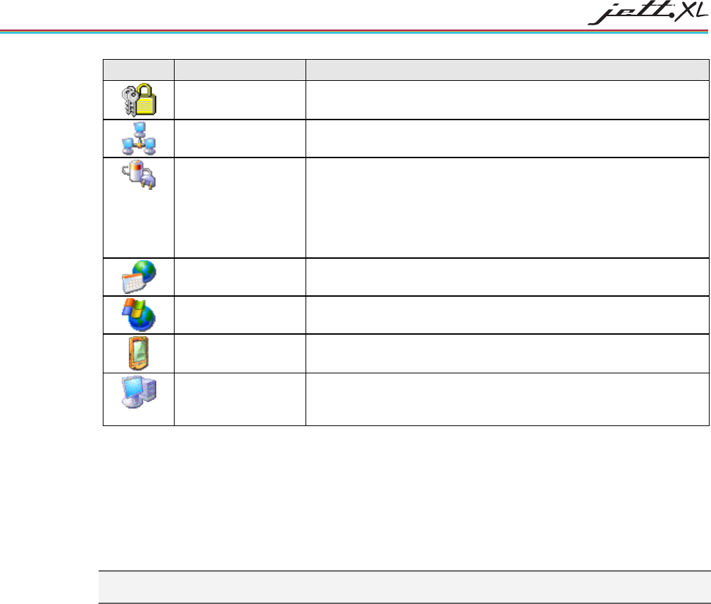
Icon Function Description
Password Use this function to enable password protection and set a password.
PC Connection Use this function to enable direct connection to a desktop computer
Power Use this function to:
Check battery power
Set device to turn off when idle
Set up power schemes
Check the power levels of your system devices
Regional Settings Use this function to change the appearance of region specific
information, such as date, time and currency.
Remove Programs This function enables you to remove programs installed in RAM.
Stylus Use this function to recalibrate the touch screen and adjust the stylus
double-tap rate.
System Use this function to view system information, change the RAM
(Program/Storage memory) division, change the device name and
change the device description.
POWER MANAGEMENT
Battery-powered units can utilize a rechargeable Nickel Metal Hydride (NiMH) battery pack that has an
average operating time of six hours on a full charge with power management.
As with all battery-powered devices, the operating time is completely dependent on the environment,
device usage and the number and type of power-drawing peripherals attached. The battery discharge rate in
a full “Power Off” state is only slightly higher to the self-discharge rate of the battery itself.
Note: Allowing the batteries to remain in a low or very low condition will cause the unit to enter Suspend mode.
In either case, you should save your work and recharge the unit as soon as possible
To lengthen the time between charges, you can perform the following actions:
• Use external power for PC Card operations whenever possible— some PC Cards as well as
extended communication via the serial port, may require large amounts of power to operate, and
can quickly drain the batteries.
• Limit the use of backlight—minimize backlight use when you are operating on battery power. You
can adjust the backlight timeout level through the Display Settings in the Control Panel or on some
units by using the keypad.
• Shorten Auto-suspend time—the JETT is automatically set to suspend operation to conserve
battery power when you have not used the keyboard or the stylus after three minutes. You can
increase the Auto-suspend time by changing the Power settings in the Control Panel.
CONFIGURATION 4-3
TASKBAR AND START MENU SETTINGS
To change the Taskbar and Start Menu settings:
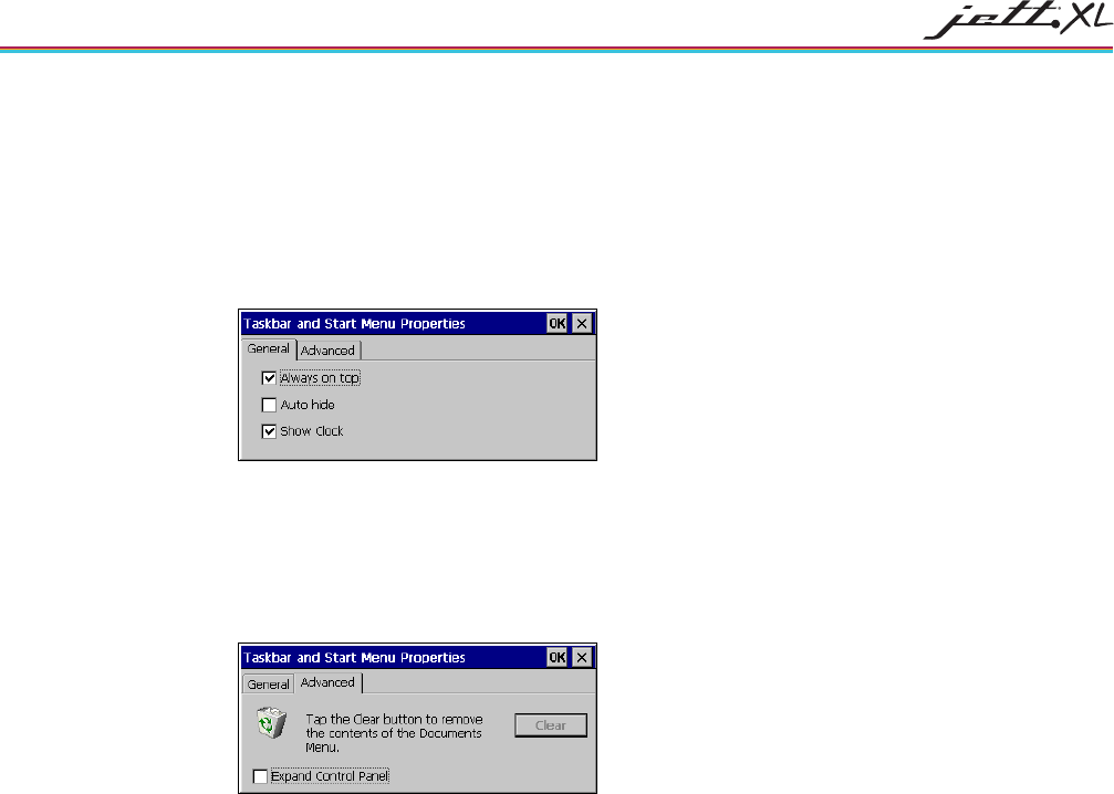
1. Select Start > Settings> Taskbar & Start Menu. The Taskbar and Start Menu Properties dialog box
opens:
2. Select the General tab:
3. Check Always on Top to ensure that the taskbar is always visible, even when a program appears in
a full window (maximized).
4. Check Auto hide to display the taskbar just when you point to the taskbar area.
5. Check Show Clock to display the time of day in the taskbar.
6. Select the Advanced tab:
7. Tap the Clear button to remove the contents of the documents menu.
8. Check the Expand Control Panel box to display the contents of the Control Panel as items on the
Settings| Control Panel menu.
9. Tap OK to save the settings and exit the menu.
5-1
CHAPTER 5
CONNECTIONS
CREATING AN ACTIVESYNC CONNECTION
ActiveSync is a desktop utility program (available as a free download from Microsoft) that allows you to
synchronize certain types of information between a PC and the JETT. You can also use ActiveSync to
transfer files and install programs on the JETT.
Notes:
The following procedures describe how to make an ActiveSync connection using a serial interface cable. If
your PC does not have a serial port, you will need to use a USB to serial port adapter
For information on how to make an ActiveSync connection using Bluetooth, WLAN or USB, refer to the
appropriate manual.
The procedures listed below document using ActiveSync 4.1. Some dialogs boxes will appear differently than
previous versions. However, the basic procedure is the same.
ActiveSync 4.0 and above only supports Remote PC Link via Bluetooth. It does not support Remote PC Link (via
WI-FI or LAN) due to enterprise customer feedback around security issues. If you must use WI-FI or LAN, use
ActiveSync version 3.8 or below.
CONFIGURING THE JETT
To setup initial communication between the PC and the JETT, you must first configure the JETT with the
correct communication setting.
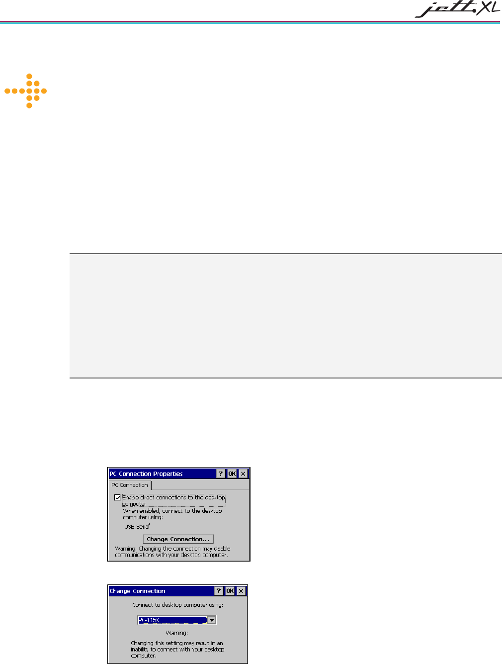
1. On the JETT, tap Settings> Control Panel > PC Connection. The PC Connection Properties Dialog
box appears.
2. Tap Change Connection. The Change Connection dialog box appears.
3. Select PC-115 and tap OK. The PC Connection Properties Dialog box reappears.
4. Tap OK to exit.
CONNECTIONS
5-2
5. Close the Control Panel and return to the desktop.
CONFIGURING THE PC
After you configure the JETT, you must configure the PC before making an ActiveSync connection.
Note: If you are installing ActiveSync on the PC for the first time and the Get Connected wizard appears, click
Cancel.
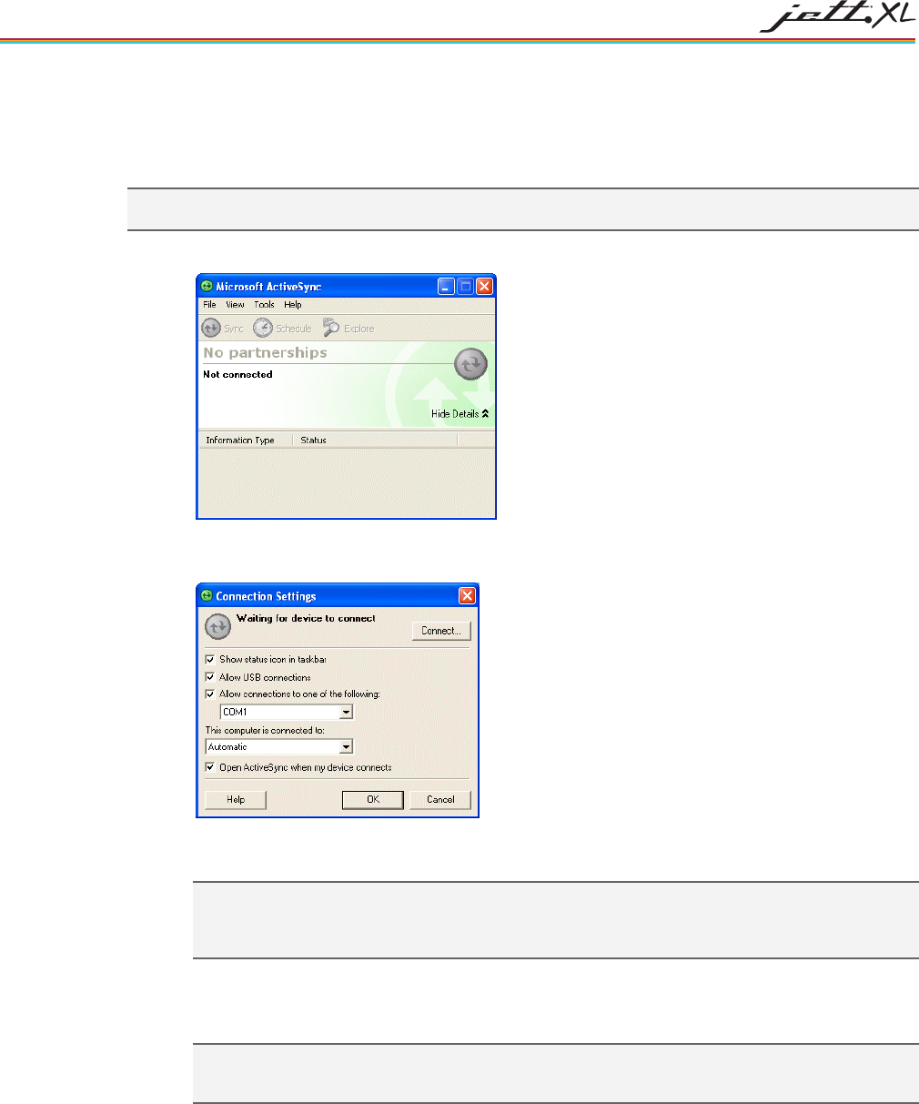
1. On the PC, start ActiveSync.
2. On the ActiveSync menu bar, select File and then Connection Settings. The Connection Settings
dialog box opens.
3. If not selected, check the Allow connection to one of the following box, and assign the number of
the available COM port (typically COM1).
Note: If you have to share a COM port with a device that has a different connectivity program, you
will need to free the COM port from ActiveSync before using the COM port for the other device. The
next time you want to connect a device to ActiveSync, you will need to assign the COM port back to
ActiveSync.
4. If needed, change how the PC should connect to when passing through ActiveSyncT (i.e., the JETT
can use the computer's network connection as if it were its own to download files or browse the
Internet). The default setting is Automatic.
Note: For additional security, disable network bridging on the PC (specifically, bridging to a Remote
NDIS adapter) before connecting to the PC to pass though to the Internet or a network. Proceed to
the next section. Do not close this dialog box.
CONNECTIONS 5-3
CREATING AN INITIAL ACTIVESYNC CONNECTION
To create an initial ActiveSync connection:
1. Connect one end of your interface cable to the serial (COM) port on your desktop computer.
Connect the other end of the cable to the JETT.
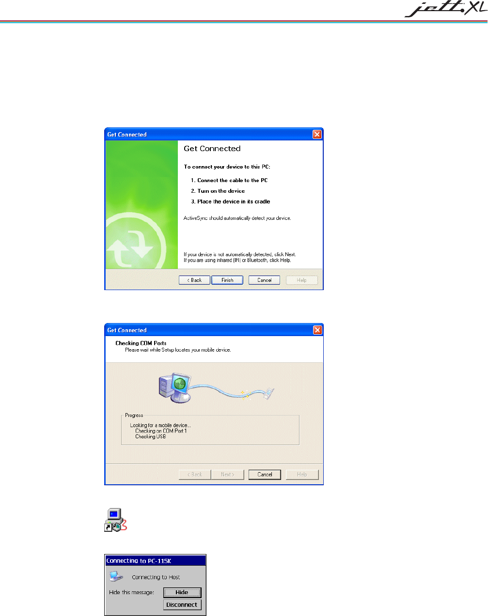
2. In the Connection Settings dialog box, click Connect. The Get Connected wizard appears
3. Click Next. ActiveSync will then attempt to establish a connection with the JETT (this process may
take several seconds).
4. On the JETT desktop, tap PC Link.
5. The following message box appears:
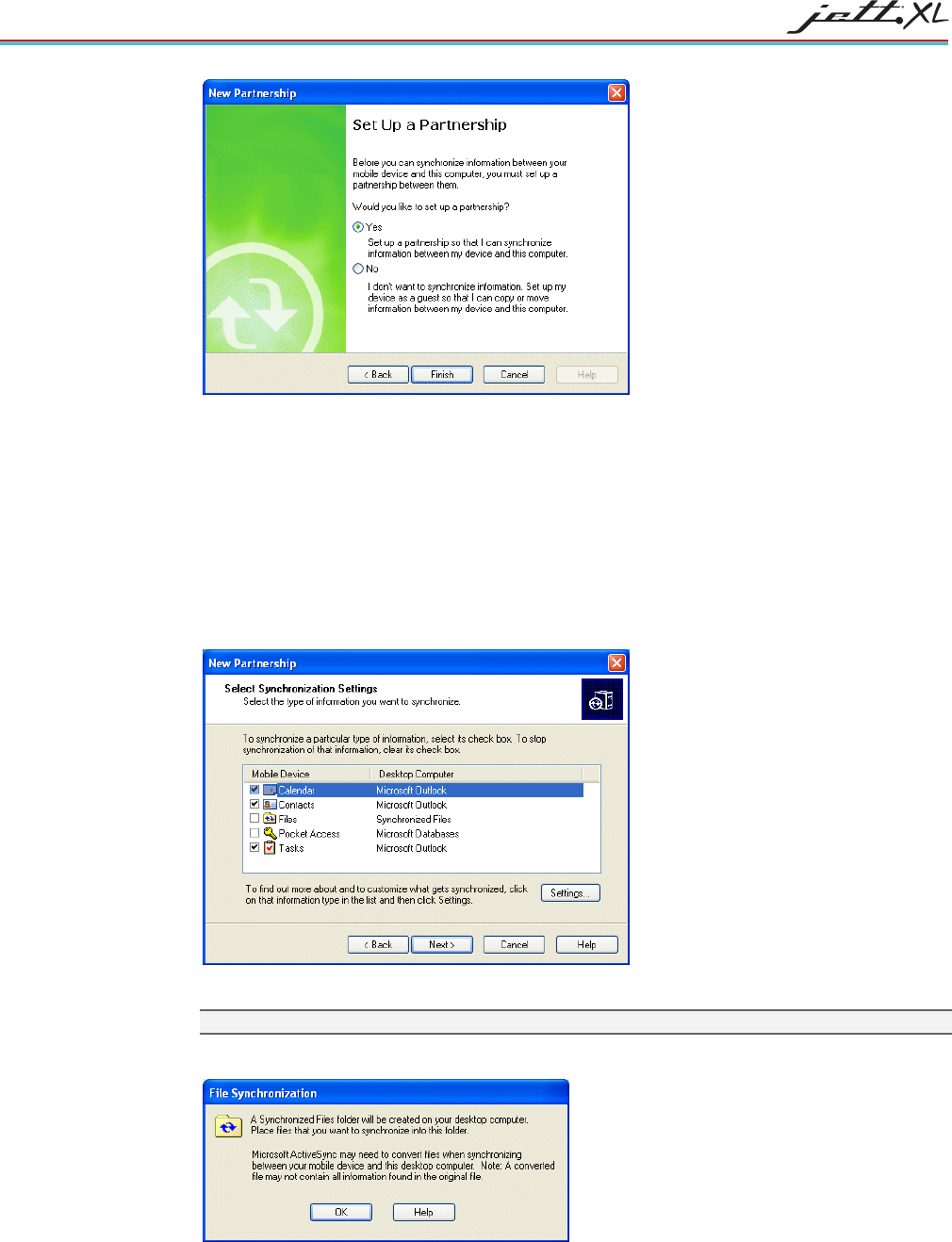
6. When ActiveSync successfully establishes communications with the JETT, the New Partnership
dialog box will appear on the PC.
CONNECTIONS
5-4
7. You can now choose to setup a partnership to synchronize files or connect as a “guest.” Refer to the
following sections to further instructions.
CREATING A PARTNERSHIP
When starting ActiveSync for the first time, you have the option to create a partnership that allows you to
synchronize selected items between the JETT and the PC.
To create a partnership during your initial setup:
1. Select Yes in the New Partnership wizard and then click Next. ActiveSync will then prompt you to
select the type of information you want to synchronize.
2. Check or clear the boxes that pertain to the type of information you want to synchronize.
Note: the JETT does not support Pocket Access or the synchronization of Pocket Access files
3. If you choose to synchronize files, the following message will appear:
4. Click OK to continue.
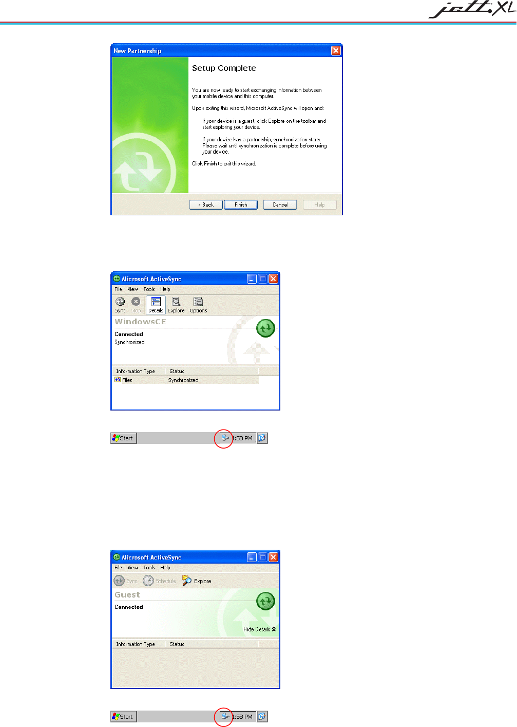
CONNECTIONS 5-5
5. Click Finish to complete the setup. ActiveSync will then create a folder on your desktop and
attempt to synchronize the item types you selected with similar items on the JETT (e.g., if you
selected Files and placed a file in the My Documents folder on the JETT, ActiveSync will transfer it
to the JETT’s folder on the desktop.
On the JETT, an icon indicating a ActiveSync connection will appear in the system tray.
CREATING A GUEST CONNECTION
If you do not require synchronization or plan to connect to the PC on a regular basis, you can set up a
"guest" connection to perform tasks such as coping files or installing programs.
To create a guest connection during your initial setup:
1. Select No in the New Partnership wizard and then click Next. The ActiveSync main menu will
reappear. A status of “Connected” should appear in the ActiveSync window.
On the JETT, an icon indicating a ActiveSync connection will appear in the system tray.
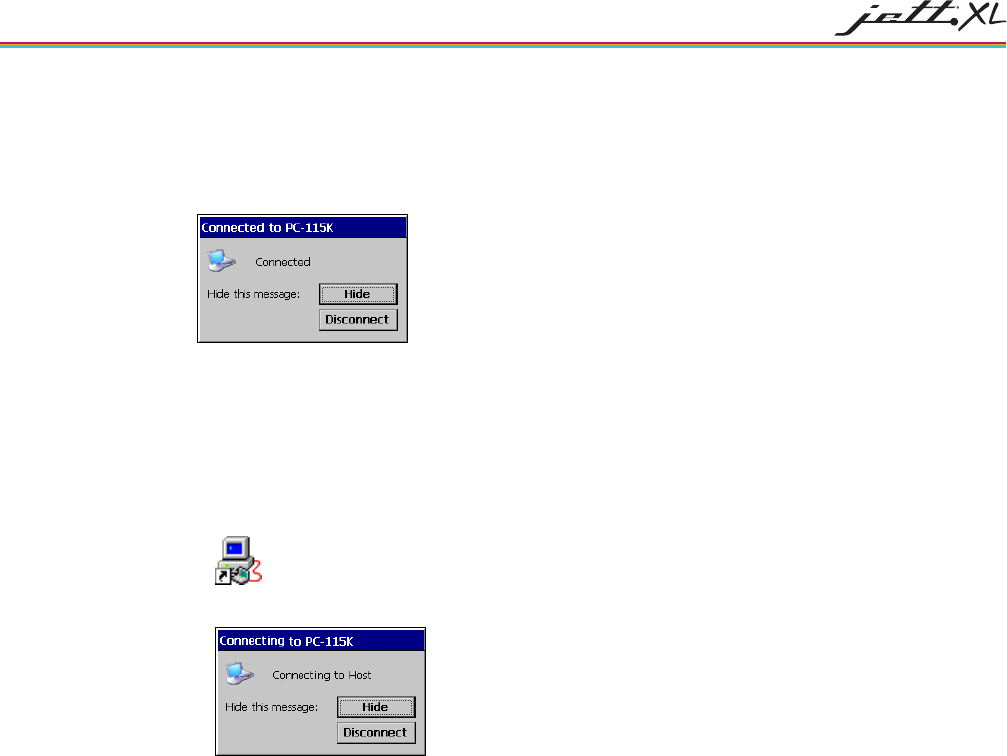
CONNECTIONS
5-6
DISCONNECTING ACTIVESYNC
To terminate the ActiveSync connection:
1. On the JETT, double-tap the connection icon in the System Tray. The PC-115K Status dialog box
appears.
2. Tap Disconnect.
SUBSEQUENT CONNECTIONS
To perform subsequent ActiveSync connections:
1. If needed, connect your interface cable between your desktop computer and the JETT.
2. On the JETT desktop, tap PC Link.
3. On the JETT, the following message box appears:
4. If you have created partnership, the ActiveSync will automatically reconnect and attempt to
synchronize any files. If you have not created a partnership, ActiveSync will display the New
Partnership wizard. In which case, you can create a partnership or a guest connection.
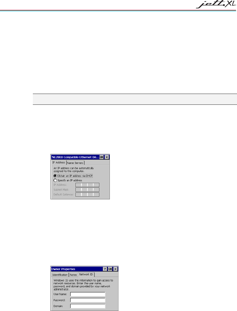
CONNECTIONS 5-7
NETWORK CONNECTIONS
CREATING A WIRELESS CONNECTION
To create a wireless network connection, using an approved wireless card or integrated option, refer to
either the JETT•XL Wi-Fi Setup and Configuration Guide or the JETT•XL Bluetooth Setup and Configuration
Guide
CREATING A WIRED ETHERNET NETWORK CONNECTION
You can connect directly to a network to access e-mail, access files available on a network server or browse
the Internet and using Socket Low Power Wired Ethernet CF card.
Note: If you are using communications cards other than those supplied by Two Technologies, you will need to
ensure that the card manufacturer supports Windows CE 5.0.
To create a Wired Ethernet connection:
5. Insert the Ethernet card into the JETT and connect the cable to the network.
6. Select Start > Settings > Control Panel. Double-tap Network and Dial-Up Connections.
7. Double-tap the connection icon for the adapter. For example, if you have a NE2001 Ethernet
adapter, double-click the NE2001 connection icon.
8. In the Ethernet Driver Settings dialog box, select Obtain an IP address via DHCP and tap OK.
9. If prompted, enter the User Name, Password, and Domain name used to log on to your network.
SETTING UP IDENTIFICATION FOR REMOTE NETWORKS
To set up identification for remote networks:
10. Select Start > Settings > Control Panel.
11. Double-tap Owner. The Owner Properties dialog box appears.
12. In the Network ID tab, enter the user name, password, and domain name you use to log on to the
remote network.
13. Tap OK to exit.
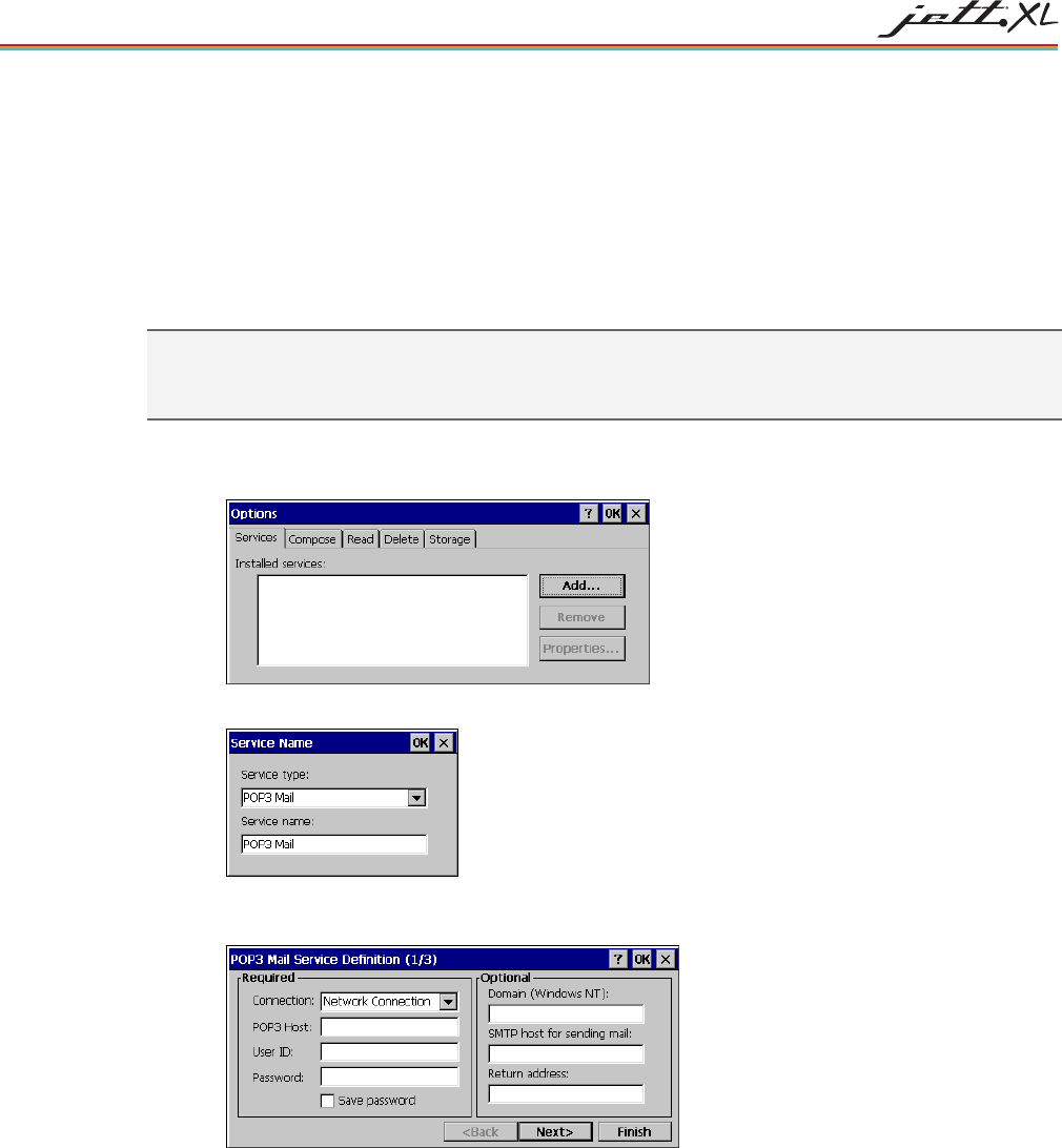
CONNECTIONS
5-8
CONNECTING TO A MAIL SERVER
You can send and receive e-mail by connecting to a POP3 or IMAP4 server. Inbox contains an e-mail service
for each method you use. For either service, you must establish a connection to your Internet service
provider (ISP) or to the appropriate mail server in your local area network. In addition to creating this
connection, you must also create the e-mail service.
Prior to setting up a service, you should obtain the following information from your ISP or network
administrator: POP3 or IMAP4 server name, SMTP host name, user name, password and domain name (for
network connections only).
Notes: Windows CE 5.0 does not support other mail protocols such as AOL or services that use special
authentication, such as MSN. However, you can gain access to the Internet through these services. If you use
the same service to connect to different mailboxes, set up and name a different service for each connection.
For additional information about the inbox, refer to Windows CE 5.0 online help.
To connect to your POP3 or IMAP4 mail server:
1. Select Start > Programs > Inbox > Services > Options. The Options dialog box opens.
2. Select the Services tab and tap Add. The Service Name dialog box opens.
3. From the Service type list, select POP3 Mail or IMAP4 Mail, enter a unique name for the service
(you cannot change this name once entered) and tap OK. The Mail Service Setup wizard appears.
4. In the Required panel:
Select the name of the connection you created to connect to the mail server. If you are receiving
e-mail through a network (Ethernet) connection, select Network Connection.
If you want Inbox to use your current connection, select (none).
If you have not created a connection, select Create new connection, double-tap the Make New
Connection icon, and follow the instructions in the wizard. When finished, select Inbox in the
Taskbar and continue setting up Inbox.
Enter the POP3 Host or Server (IMAP4) name of the mail server you use to receive and send
messages.
Enter the User ID (user name or mailbox ID) assigned to you.
Enter the Password you will use to access this mail account. If you do not want a prompt to
enter the password each time you connect, select Save password.
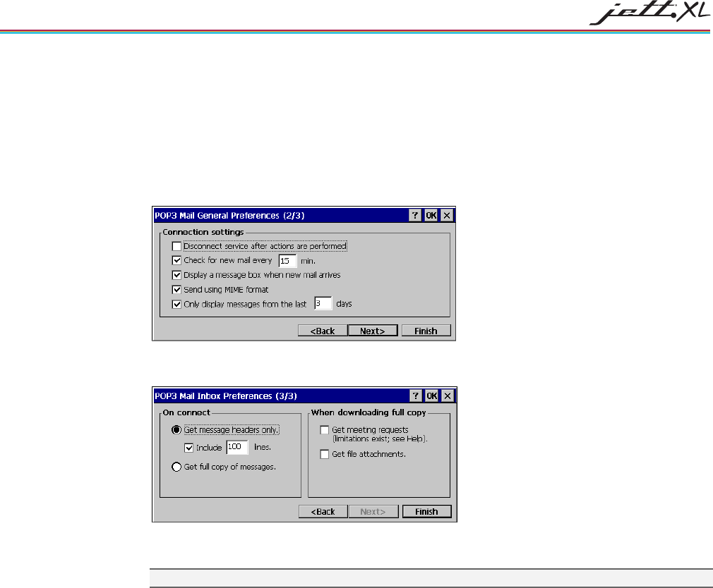
CONNECTIONS 5-9
5. In the Optional panel:
If connecting to a network that uses Windows NT domain security, enter the Windows NT
domain name.
If your mail service uses a separate server for SMTP, enter the SMTP Host name. For POP3
Mail service with an ISP, the ISP must use an SMTP mail gateway.
Enter your return e-mail address.
6. Tap Next. The General Preferences dialog box opens.
7. Choose any of the settings, all of which are optional, then click Next. The Inbox Preferences dialog
box opens.
8. Choose any of the settings as needed, then click Finish. The Mail Service Setup wizard closes and
the Options dialog box reappears.
Note: Receiving entire messages consumes storage memory.
9. Close the Options dialog box to return to the Inbox. .

6-1
CHAPTER 6
TROUBLESHOOTING
MY JETT DOES NOT RESPOND WHEN I PRESS THE POWER BUTTON.
• Is the unit in Suspend mode?
• If battery-powered, check the batteries.
• Are all cables connected properly:
Is the power supply plugged into an active AC outlet?
Is the power connector securely plugged into the JETT?
I CHANGED MY SYSTEM SETTINGS, BUT WHEN I TURN ON THE JETT, MY SETTINGS ARE GONE.
• You must save the registry after making any system or configuration changes.
I TRANSFERRED FILES TO THE JETT FROM MY HOST COMPUTER, BUT WHEN I TURN ON THE JETT
MY TRANSFERRED FILES ARE MISSING.
• To store transferred files permanently, you must file copy the files into internal flash memory or a
compact flash card.
Occasionally, transferred files can be hidden from view, double-tap My Computer, select Options
from the View menu and clear all boxes.
I CANNOT CONNECT TO THE DEVELOPMENT SYSTEM USING ACTIVESYNC.
• Did you install ActiveSync using the Administrator account?
• Check the cable connections.
• Check the serial communications configuration.
• Make sure the correct COM port is available.
• In ActiveSync, check the Connection Settings for the connection type you are using (USB, Serial or
Ethernet).
THE SCREEN IS TOO LIGHT OR TOO DARK.
• Adjust the brightness via the brightness control in the Control Panel.
THE STYLUS IS NOT RESPONDING PROPERLY.
• The screen is not calibrated correctly to interpret the screen taps. You need to recalibrate the screen.

TROUBLESHOOTING
6-2
THE JETT ACTS SLOWLY.
• The unit may be short of program memory or storage memory.
• Increase the amount of storage or program memory through the System control in the Control
Panel.
• You can also delete any unnecessary files.
I GET LITTLE OR NO SOUND FROM THE JETT.
• Adjust the volume and sound properties via the Volume and Sound control in the Control Panel.
THE JETT DOES NOT RECOGNIZE A COMPACT FLASH OR DEVICE CARD.
• The card is not installed or seated properly.
• Reinstall the card. There may be an unstable connection between the card and the JETT.
• Remove the card, clean the edge connector with a soft dry cloth, and reinstall the card.
THE JETT GOES INTO AUTO-SUSPEND AFTER A SHORT PERIOD OF INACTIVITY.
• As a default, the device will auto-suspend after two minutes of inactivity while running on
batteries and after thirty minutes of inactivity when running on AC power.
• Adjust the power management properties via the Power control in the Control Panel.
NO SOUND IS HEARD WHEN YOU TAP THE TOUCH SCREEN OR PRESS A KEY.
• Volume setting is low or turned off.
• Check the volume slider in the Volume & Sound properties dialog box in the Control Panel.

SPECIFICATIONS A-1
APPENDIX A
SPECIFICATIONS
POWER
Recharge/Line-Power: 11 to 18 VDC, 1.2A
Standard: Input at 11 to 18 VDC via JETT•connect system interface for line-power or battery charging
operations
Optional: Output at 5 VDC @ 1.2A to operate peripheral devices (either port)
Rechargeable Battery Type: Nickel Metal Hydride (or 6 AA alkaline batteries)
Current Rating: 2 Amp Maximum
Voltage: 7.2 Volts
Capacity: 2500 mAh
DISPLAY
Supertwist Nematic Liquid Crystal TFT Touch Screen with white LED backlight
Resolution: 320 x 240 pixels QVGA color
CPU
Type: Intel PXA270 processor
Speed: up to 624 MHz
Operating System: Windows CE 5.0
MEMORY AND MASS STORAGE
SDRAM: 128 MB (256 MB optional)
Internal Compact Flash: 512 MB standard (30 MB reserved for OS), upgradeable to 2 GB
Optional: Compact flash card slot
USER INPUT
Touch Screen
Key Pad: Choice of 52-key joystick style elastomeric keypad, 45-key elastomeric keypad (9 rows x 5
columns), 30-key elastomeric keypad (10 rows x 3 columns), 15-key elastomeric (5 x 3), or 45-yey
membrane (9 rows x 5 columns)
Feedback: Tactile and audible
Optional: LED backlighting
INDICATORS
5 Modifier Key/Programmable LEDs
Charge/Low Battery Indicator (battery-powered units only)
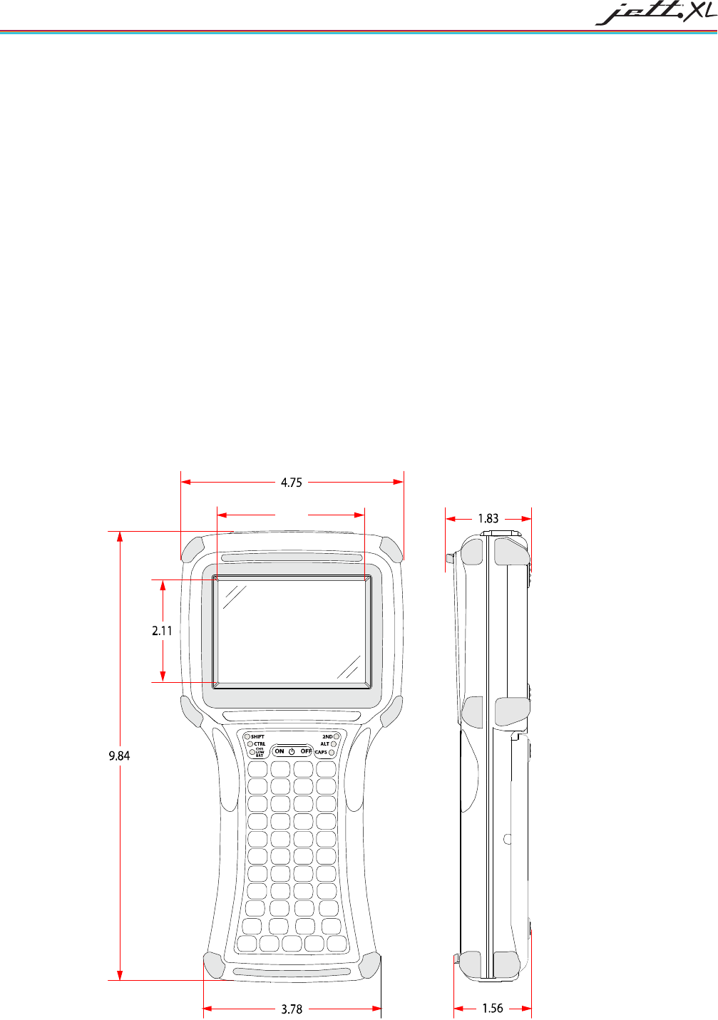
SPECIFICATIONS
A-2
CONNECTIVITY
Standard: JETT•connect serial port with choice of full RS-232 or a choice of two of the following: short
RS-232 (2), short RS-422, short RS-485 or USB.
Optional: Bluetooth (Class 1 or 2) ,Wi-Fi (802.11b) or GPRS
ENVIRONMENTAL
Operating Temperature: -20°C to +50°C
Storage Temperature: -20°C to +70°C
Charging Temperature: -20°C to + 40°C
Humidity: 5-95% Non-condensing
IP Rating: 65
PHYSICAL DIMENSIONS
Height (H): 9.84 Inches (250 mm)
Width (W): 4.75 Inches (120.7 mm)
Depth (D): 1.83 Inches (46.5 mm)
Weight with NiMH Batteries: 29 Ounces (822 grams)
Weight with Alkaline Batteries: 28 Ounces (794 grams)
Weight without Batteries: 23 Ounces (652 grams)
Figure A-1: Case Dimensions
2.82
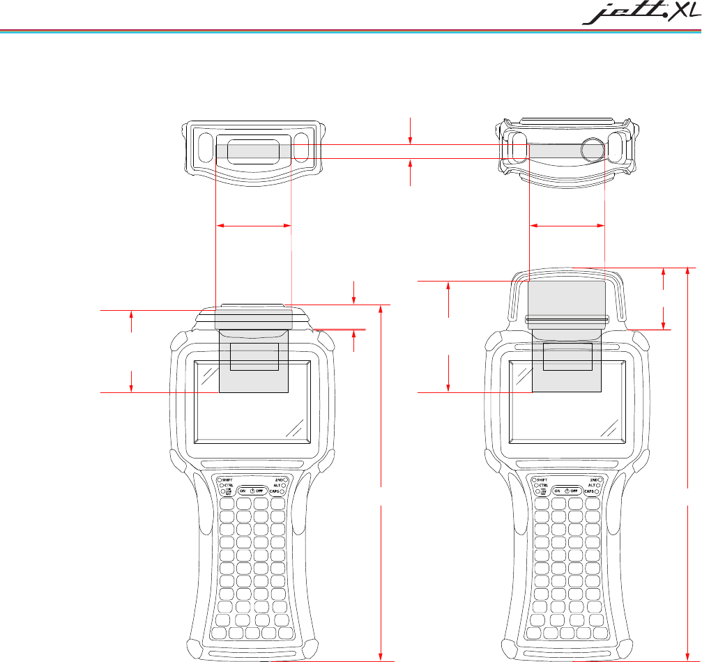
TROUBLESHOOTING A-3
Figure A-2: Case Dimension with JETT•HATCH
2.75" Maximum Card
Height
1.70"
0.73"
Maximum Thickness
of Card Width
11.45
"
1.936"
Maximum
Card Width
1.936"
Maximum
Card Width
1.687" Maximum Card
Height
0.593"
10.33"
Low Profil
e
High Profile
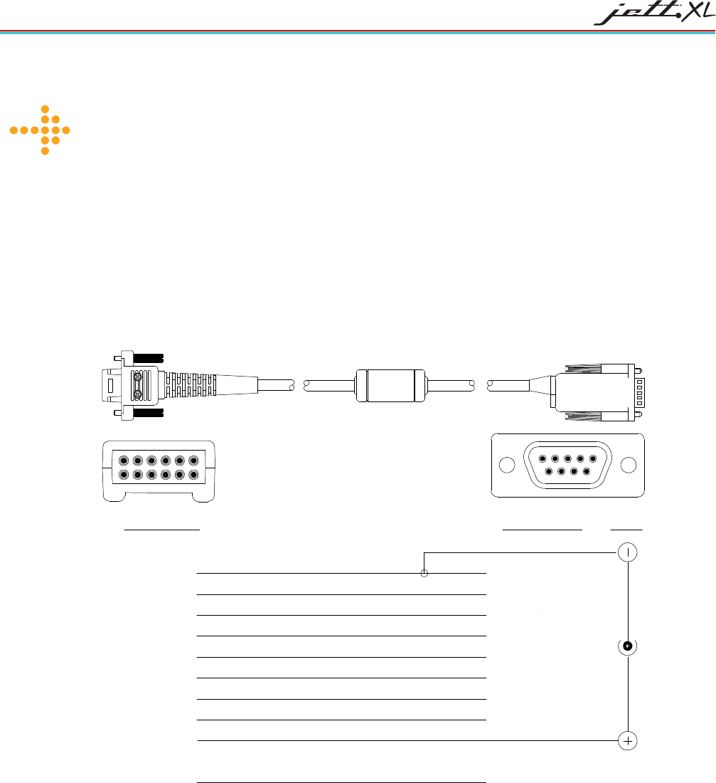
B-1
APPENDIX B
SIGNAL AND PIN ASSIGNMENTS
JETT•CONNECT CABLES
Figures B-1 and B-2 list the standard RS-232 signal and pin assignments for the JETT•connect cables.
Figure B-1: 91708 Cable (Male DE9) RS-232 Signal and Pin Assignments
JETT• Connect DE 9 Connector
9
8
76
54321
9
8
7
6
5
4
3
2
111
1012
Pin 1 (Reserved)
Pin 2 (GND)
Pin 3 (RI)
Blue
Pin 4 (CTS)
Pin 5 (DTR)
Pin 6 (TXD)
Pin 7 (DSR)
Pin 8 (RTS)
Pin 9 (DCD)
Pin 10 (PWR)
Pin 11 (SHIELD)
Pin 12 (RXD)
Pin 5 (GND)
Pin 9 (RI)
Pin 8 (CTS)
Pin 4 (DTR)
Pin 3 (TXD)
Pin 1 (DCD)
Pin 2 (RXD)
Pin 6 (DSR)
Pin 7 (RTS)
Power
White w/Black Stripe
Gray
Black
Violet
Yellow
Brown
Red
Orange
White
Green
Viewed Facing
Connector
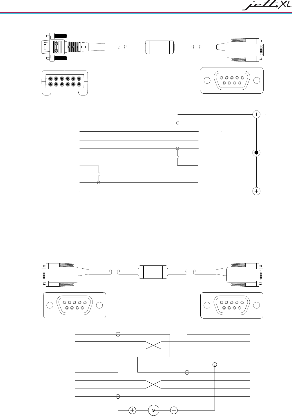
SIGNAL AND PIN ASSIGNMENTS
B-2
Figure B-2: 91709 Cable (Female DE9) RS-232 Signal and Pin Assignments
JETT• Connect DE 9 Connector
9876
54321
9
8
7
6
5
4
3
2
111
1012
Pin 1 (Reserved)
Pin 2 (GND)
Pin 3 (RI)
Pin 4 (CTS)
Pin 5 (DTR)
Pin 6 (TXD)
Pin 7 (DSR)
Pin 8 (RTS)
Pin 9 (DCD)
Pin 10 (PWR)
Pin 11 (SHIELD)
Pin 12 (RXD)
Pin 5 (GND)
Pin 9 (RI In)
Pin 7 (CTS In)
Pin 1 (DTR Out)
Pin 2 (TXD Out)
Pin 4 (DSR/DCD In)
Pin 3 (RXD In)
Pin 6 (DTR Out)
Pin 8 (RTS Out)
Power
Viewed Facing
Connector
Blue
Gray
Red
Orange
Green
Brown
Black
Violet
White
Yellow
White w\Black Stripe
Violet
NULL MODEM CABLE
Figure B-3 lists the signal and pin assignments for Two Technologies’ 14375 DE-9 Female to DE-9 Female
null modem cable. Please note that this cable differs from standard null modem cables in that it uses Pin 9
for input power for the JETT.
Figure B-3: DE-9 Female to DE-9 Female Null Modem Cable
9
8
76
54321
Female DE9 Connector
Pin 1 (Blue)
Pin 2 (Green)
Pin 3 (Yellow)
Pin 4 (Orange)
Pin 5 (Gray)
Pin 6 (Blue)
Pin 7 (Red)
Pin 8 (Violet)
Pin 9 (Brown)
Pin 7
Pin 9
Pin 8
Pin 3
Pin 6
Pin 5
Pin 4
Pin 2
Pin 1
Power Jack
Female DE9 Connecto
r
Viewed Facing
Connector
9
8
76
54321

I-1
INDEX
1
15-Key Keypad....................................................................... 3-7
2
2ND Key................................................................................. 3-6
3
30-Key Keypad....................................................................... 3-7
4
45-Key Keypad Modifier Keys............................................... 3-6
45-Key Keypads..................................................................... 3-5
5
52-Key Keypads..................................................................... 3-5
A
About the JETT•XL................................................................ 1-2
About this Manual .................................................................. 1-1
About Two Technologies ....................................................... 1-1
ActiveSync
Configuring the JETT......................................................... 5-1
Configuring the PC............................................................. 5-2
Creating a Guest Connection.............................................. 5-5
Creating a Partnership........................................................ 5-4
Creating an ActiveSync Connection................................... 5-1
Creating an Initial ActiveSync Connection........................ 5-3
Disconnecting ActiveSync ................................................. 5-6
Subsequent Connections..................................................... 5-6
Aux CF Card........................................................................... 4-1
Aux Switch............................................................................. 4-1
B
Backlight ................................................................................ 4-1
Battery LED............................................................................ 2-2
Battery Select.......................................................................... 4-1
Beep Select............................................................................. 4-1
C
CE Keyboard .......................................................................... 3-8
Certificates.............................................................................. 4-1
Changing Batteries..................................................................3-4
Charge\Low Battery Indicator.................................................3-2
Charge\Low Battery Indicator Functions ................................3-2
Charging the Unit....................................................................3-3
CHG Indicator.........................................................................3-2
Command Prompt Windows .................................................3-12
Compact Flash Slot Cover.......................................................2-4
Components and Indicators.....................................................2-1
Configuration ..........................................................................4-1
Configuration Options.............................................................1-3
Configuring the JETT, ActiveSync.........................................5-1
Configuring the PC, ActiveSync.............................................5-2
Connecting to a Mail Server....................................................5-8
Connections.............................................................................5-1
Connectivity...........................................................................A-2
Connector Covers....................................................................1-3
Control Panel...........................................................................4-1
CPU........................................................................................A-1
CPU Speed..............................................................................4-1
Creating a Guest Connection, ActiveSync ..............................5-5
Creating a Partnership, ActiveSync.........................................5-4
Creating a Wired Ethernet Network Connection.....................5-7
Creating a Wireless Connection..............................................5-7
Creating an ActiveSync Connection........................................5-1
Creating an Initial ActiveSync Connection.............................5-3
CTRL and ALT Keys..............................................................3-6
D
Data Entry...............................................................................3-5
Date/Time................................................................................4-1
DE-9 Connectors.....................................................................2-3
Dialing.....................................................................................4-1
Disconnecting ActiveSync ......................................................5-6
Display.................................................................... 2-1, 4-1, A-1
Display Rotation......................................................................4-1
Displays...................................................................................1-2
Durability................................................................................1-3
E
Environmental........................................................................A-2
F
Front Components...................................................................2-1
Front Components and Indicators ...........................................2-2
Front Panel.......................................................................2-1, 2-2
Fully/Near Full Charge............................................................3-2

INDEX
I-2
H
High Power Charge ................................................................ 3-2
Hot Keys................................................................................. 4-1
I
Inbox....................................................................................... 3-9
Indicators........................................................................ 1-2, A-1
Ingress Protection................................................................... 1-3
Interface Connections............................................................. 2-2
Internet Explorer..................................................................... 3-9
Internet Options...................................................................... 4-1
J
JETT•connect Cables..............................................................B-1
JETT•connect System............................................................. 2-2
JETT•HATCH........................................................................ 2-5
JETT•XL Features.................................................................. 1-2
K
Key Repeat ............................................................................. 3-7
Keyboard ................................................................................ 4-1
Keypad.................................................................................... 2-1
Keypad Modifier Key............................................................. 3-6
Keypads........................................................................... 1-2, 3-5
L
LOW BAT Indicator............................................................... 3-2
M
Manually Saving the Persistent Registry .............................. 3-12
Memory and Mass Storage ............................................. 1-2, A-1
Microsoft WordPad ................................................................ 3-9
Miscellaneous Tools............................................................. 3-10
Modifier LEDs........................................................................ 2-2
My Device.............................................................................. 3-9
My Documents ....................................................................... 3-9
N
Network and Dial-up Connections.......................................... 4-1
Network Connections ............................................................. 5-7
Null Modem Cable .................................................................B-2
O
On/Off Switch .................................................................2-2, 3-1
Operating System ................................................................... 1-2
Operation................................................................................ 3-1
Overview ................................................................................ 1-1
Owner..................................................................................... 4-1
P
Password .................................................................................4-2
PC Connection ........................................................................4-2
PC Link...................................................................................3-9
Physical Dimensions ..............................................................A-2
Power ...................................................................... 3-1, 4-2, A-1
Power Jack ..............................................................................2-4
Power Management.................................................................4-2
Power Off................................................................................3-1
Power On.................................................................................3-1
Power Status Icons ................................................................3-10
Power Supplies, Cables and Adapters.....................................2-5
Power Supply..........................................................................3-3
Processor.................................................................................1-2
R
Rechargeable Battery Pack......................................................1-2
Recycle Bin.............................................................................3-9
Regional Settings ....................................................................4-2
Related Documents .................................................................1-1
Remove Programs...................................................................4-2
Replacing Batteries/Battery Pack............................................3-4
S
Screen Capture ......................................................................3-10
Setting Up Identification for Remote Networks......................5-7
SHIFT Key..............................................................................3-6
Signal and Pin Assignments...................................................B-1
Specifications.........................................................................A-1
Stylus.......................................................................................4-2
Subsequent Connections, ActiveSync.....................................5-6
Suspend...................................................................................3-1
Suspend Mode.........................................................................3-2
System.....................................................................................4-2
SystemCF Folder...................................................................3-12
T
Taskbar....................................................................................3-9
Taskbar and Start Menu Settings.............................................4-3
The Start Menu......................................................................3-10
Transcriber ..............................................................................3-8
Troubleshooting ......................................................................6-1
U
User Input...............................................................................A-1
Using the 5VDC Output Line to Power External Devices.......2-3
Using the Compact Flash Slot...............................................3-13
W
Warm Boot............................................................................3-11
Windows CE 5.0 Desktop .......................................................3-9
Windows CE 5.0 Desktop Functions.......................................3-9