Tyco Safety Canada 00433904 Wireless Motion Detector User Manual WLS904L inis eng 29005255 r001 p65

Digital Security Controls Ltd. Wireless Motion Detector WLS904L inis eng 29005255 r001 p65

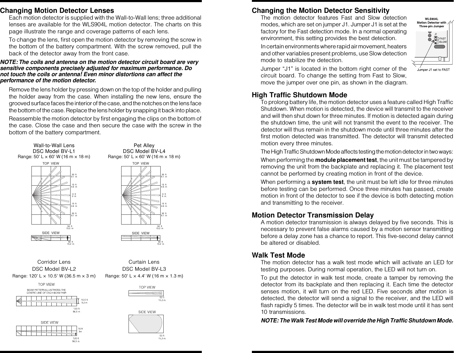
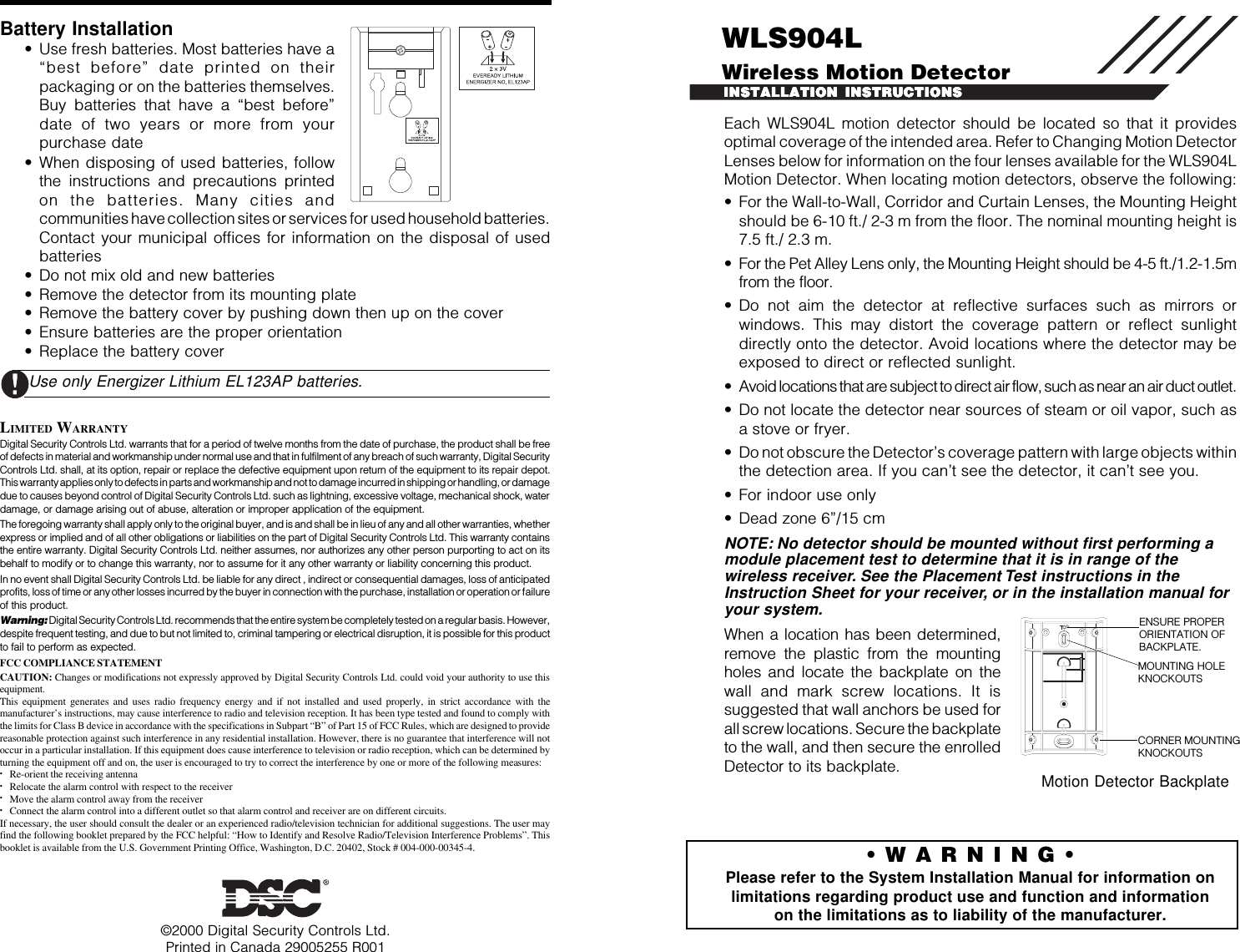
Installation instructions

Each WLS904L motion detector should be located so that it providesoptimal coverage of the intended area. Refer to Changing Motion DetectorLenses below for information on the four lenses available for the WLS904LMotion Detector. When locating motion detectors, observe the following:• For the Wall-to-Wall, Corridor and Curtain Lenses, the Mounting Heightshould be 6-10 ft./ 2-3 m from the floor. The nominal mounting height is7.5 ft./ 2.3 m.• For the Pet Alley Lens only, the Mounting Height should be 4-5 ft./1.2-1.5mfrom the floor.• Do not aim the detector at reflective surfaces such as mirrors orwindows. This may distort the coverage pattern or reflect sunlightdirectly onto the detector. Avoid locations where the detector may beexposed to direct or reflected sunlight.• Avoid locations that are subject to direct air flow, such as near an air duct outlet.• Do not locate the detector near sources of steam or oil vapor, such asa stove or fryer.• Do not obscure the Detector’s coverage pattern with large objects withinthe detection area. If you can’t see the detector, it can’t see you.• For indoor use only• Dead zone 6”/15 cmNOTE: No detector should be mounted without first performing amodule placement test to determine that it is in range of thewireless receiver. See the Placement Test instructions in theInstruction Sheet for your receiver, or in the installation manual foryour system.When a location has been determined,remove the plastic from the mountingholes and locate the backplate on thewall and mark screw locations. It issuggested that wall anchors be used forall screw locations. Secure the backplateto the wall, and then secure the enrolledDetector to its backplate.©2000 Digital Security Controls Ltd.Printed in Canada 29005255 R001INSTALLATION INSTRUCTIONSINSTALLATION INSTRUCTIONSINSTALLATION INSTRUCTIONSINSTALLATION INSTRUCTIONSINSTALLATION INSTRUCTIONSBattery Installation• Use fresh batteries. Most batteries have a“best before” date printed on theirpackaging or on the batteries themselves.Buy batteries that have a “best before”date of two years or more from yourpurchase date• When disposing of used batteries, followthe instructions and precautions printedon the batteries. Many cities andcommunities have collection sites or services for used household batteries.Contact your municipal offices for information on the disposal of usedbatteries• Do not mix old and new batteries• Remove the detector from its mounting plate• Remove the battery cover by pushing down then up on the cover• Ensure batteries are the proper orientation• Replace the battery coverUse only Energizer Lithium EL123AP batteries.LIMITED WARRANTYDigital Security Controls Ltd. warrants that for a period of twelve months from the date of purchase, the product shall be freeof defects in material and workmanship under normal use and that in fulfilment of any breach of such warranty, Digital SecurityControls Ltd. shall, at its option, repair or replace the defective equipment upon return of the equipment to its repair depot.This warranty applies only to defects in parts and workmanship and not to damage incurred in shipping or handling, or damagedue to causes beyond control of Digital Security Controls Ltd. such as lightning, excessive voltage, mechanical shock, waterdamage, or damage arising out of abuse, alteration or improper application of the equipment.The foregoing warranty shall apply only to the original buyer, and is and shall be in lieu of any and all other warranties, whetherexpress or implied and of all other obligations or liabilities on the part of Digital Security Controls Ltd. This warranty containsthe entire warranty. Digital Security Controls Ltd. neither assumes, nor authorizes any other person purporting to act on itsbehalf to modify or to change this warranty, nor to assume for it any other warranty or liability concerning this product.In no event shall Digital Security Controls Ltd. be liable for any direct , indirect or consequential damages, loss of anticipatedprofits, loss of time or any other losses incurred by the buyer in connection with the purchase, installation or operation or failureof this product.Warning: Digital Security Controls Ltd. recommends that the entire system be completely tested on a regular basis. However,despite frequent testing, and due to but not limited to, criminal tampering or electrical disruption, it is possible for this productto fail to perform as expected.FCC COMPLIANCE STATEMENTCAUTION: Changes or modifications not expressly approved by Digital Security Controls Ltd. could void your authority to use thisequipment.This equipment generates and uses radio frequency energy and if not installed and used properly, in strict accordance with themanufacturer’s instructions, may cause interference to radio and television reception. It has been type tested and found to comply withthe limits for Class B device in accordance with the specifications in Subpart “B” of Part 15 of FCC Rules, which are designed to providereasonable protection against such interference in any residential installation. However, there is no guarantee that interference will notoccur in a particular installation. If this equipment does cause interference to television or radio reception, which can be determined byturning the equipment off and on, the user is encouraged to try to correct the interference by one or more of the following measures:•Re-orient the receiving antenna•Relocate the alarm control with respect to the receiver•Move the alarm control away from the receiver•Connect the alarm control into a different outlet so that alarm control and receiver are on different circuits.If necessary, the user should consult the dealer or an experienced radio/television technician for additional suggestions. The user mayfind the following booklet prepared by the FCC helpful: “How to Identify and Resolve Radio/Television Interference Problems”. Thisbooklet is available from the U.S. Government Printing Office, Washington, D.C. 20402, Stock # 004-000-00345-4. • W A R N I N G •Please refer to the System Installation Manual for information onlimitations regarding product use and function and informationon the limitations as to liability of the manufacturer.CORNER MOUNTINGKNOCKOUTSENSURE PROPERORIENTATION OFBACKPLATE.MOUNTING HOLEKNOCKOUTSMotion Detector BackplateWLS904LWireless Motion Detector
Changing Motion Detector LensesEach motion detector is supplied with the Wall-to-Wall lens; three additionallenses are available for the WLS904L motion detector. The charts on thispage illustrate the range and coverage patterns of each lens.To change the lens, first open the motion detector by removing the screw inthe bottom of the battery compartment. With the screw removed, pull theback of the detector away from the front case.NOTE: The coils and antenna on the motion detector circuit board are verysensitive components precisely adjusted for maximum performance. Donot touch the coils or antenna! Even minor distortions can affect theperformance of the motion detector.Remove the lens holder by pressing down on the top of the holder and pullingthe holder away from the case. When installing the new lens, ensure thegrooved surface faces the interior of the case, and the notches on the lens facethe bottom of the case. Replace the lens holder by snapping it back into place.Reassemble the motion detector by first engaging the clips on the bottom ofthe case. Close the case and then secure the case with the screw in thebottom of the battery compartment.Wall-to-Wall Lens Pet AlleyDSC Model BV-L1 DSC Model BV-L4Range: 50' L × 60' W (16 m × 18 m) Range: 50' L × 60' W (16 m × 18 m)50 ft15.2 m0ft0m15 ft4.6 m15 ft4.6 m30 ft9.1 m30 ft9.1 m50 ft15.2 mTOP VIEWSIDE VIEW50 ft15.2 m0ft0m15 ft4.6 m15 ft4.6 m30 ft9.1 m30 ft9.1 m50 ft15.2 mTOP VIEWSIDE VIEWCorridor Lens Curtain LensDSC Model BV-L2 DSC Model BV-L3Range: 120' L × 10.5' W (36.5 m × 3 m) Range: 50' L × 4.4' W (16 m × 1.3 m)Changing the Motion Detector SensitivityThe motion detector features Fast and Slow detectionmodes, which are set on jumper J1. Jumper J1 is set at thefactory for the Fast detection mode. In a normal operatingenvironment, this setting provides the best detection.In certain environments where rapid air movement, heatersand other variables present problems, use Slow detectionmode to stabilize the detection.Jumper “J1” is located in the bottom right corner of thecircuit board. To change the setting from Fast to Slow,move the jumper over one pin, as shown in the diagram.High Traffic Shutdown ModeTo prolong battery life, the motion detector uses a feature called High TrafficShutdown. When motion is detected, the device will transmit to the receiverand will then shut down for three minutes. If motion is detected again duringthe shutdown time, the unit will not transmit the event to the receiver. Thedetector will thus remain in the shutdown mode until three minutes after thefirst motion detected was transmitted. The detector will transmit detectedmotion every three minutes.The High Traffic Shutdown Mode affects testing the motion detector in two ways:When performing the module placement test, the unit must be tampered byremoving the unit from the backplate and replacing it. The placement testcannot be performed by creating motion in front of the device.When performing a system test, the unit must be left idle for three minutesbefore testing can be performed. Once three minutes has passed, createmotion in front of the detector to see if the device is both detecting motionand transmitting to the receiver.Motion Detector Transmission DelayA motion detector transmission is always delayed by five seconds. This isnecessary to prevent false alarms caused by a motion sensor transmittingbefore a delay zone has a chance to report. This five-second delay cannotbe altered or disabled.Walk Test ModeThe motion detector has a walk test mode which will activate an LED fortesting purposes. During normal operation, the LED will not turn on.To put the detector in walk test mode, create a tamper by removing thedetector from its backplate and then replacing it. Each time the detectorsenses motion, it will turn on the red LED. Five seconds after motion isdetected, the detector will send a signal to the receiver, and the LED willflash rapidly 5 times. The detector will be in walk test mode until it has sent10 transmissions.NOTE: The Walk Test Mode will override the High Traffic Shutdown Mode.
Each WLS904L motion detector should be located so that it providesoptimal coverage of the intended area. Refer to Changing Motion DetectorLenses below for information on the four lenses available for the WLS904LMotion Detector. When locating motion detectors, observe the following:• For the Wall-to-Wall, Corridor and Curtain Lenses, the Mounting Heightshould be 6-10 ft./ 2-3 m from the floor. The nominal mounting height is7.5 ft./ 2.3 m.• For the Pet Alley Lens only, the Mounting Height should be 4-5 ft./1.2-1.5mfrom the floor.• Do not aim the detector at reflective surfaces such as mirrors orwindows. This may distort the coverage pattern or reflect sunlightdirectly onto the detector. Avoid locations where the detector may beexposed to direct or reflected sunlight.• Avoid locations that are subject to direct air flow, such as near an air duct outlet.• Do not locate the detector near sources of steam or oil vapor, such asa stove or fryer.• Do not obscure the Detector’s coverage pattern with large objects withinthe detection area. If you can’t see the detector, it can’t see you.• For indoor use only• Dead zone 6”/15 cmNOTE: No detector should be mounted without first performing amodule placement test to determine that it is in range of thewireless receiver. See the Placement Test instructions in theInstruction Sheet for your receiver, or in the installation manual foryour system.When a location has been determined,remove the plastic from the mountingholes and locate the backplate on thewall and mark screw locations. It issuggested that wall anchors be used forall screw locations. Secure the backplateto the wall, and then secure the enrolledDetector to its backplate.©2000 Digital Security Controls Ltd.Printed in Canada 29005255 R001INSTALLATION INSTRUCTIONSINSTALLATION INSTRUCTIONSINSTALLATION INSTRUCTIONSINSTALLATION INSTRUCTIONSINSTALLATION INSTRUCTIONSBattery Installation• Use fresh batteries. Most batteries have a“best before” date printed on theirpackaging or on the batteries themselves.Buy batteries that have a “best before”date of two years or more from yourpurchase date• When disposing of used batteries, followthe instructions and precautions printedon the batteries. Many cities andcommunities have collection sites or services for used household batteries.Contact your municipal offices for information on the disposal of usedbatteries• Do not mix old and new batteries• Remove the detector from its mounting plate• Remove the battery cover by pushing down then up on the cover• Ensure batteries are the proper orientation• Replace the battery coverUse only Energizer Lithium EL123AP batteries.LIMITED WARRANTYDigital Security Controls Ltd. warrants that for a period of twelve months from the date of purchase, the product shall be freeof defects in material and workmanship under normal use and that in fulfilment of any breach of such warranty, Digital SecurityControls Ltd. shall, at its option, repair or replace the defective equipment upon return of the equipment to its repair depot.This warranty applies only to defects in parts and workmanship and not to damage incurred in shipping or handling, or damagedue to causes beyond control of Digital Security Controls Ltd. such as lightning, excessive voltage, mechanical shock, waterdamage, or damage arising out of abuse, alteration or improper application of the equipment.The foregoing warranty shall apply only to the original buyer, and is and shall be in lieu of any and all other warranties, whetherexpress or implied and of all other obligations or liabilities on the part of Digital Security Controls Ltd. This warranty containsthe entire warranty. Digital Security Controls Ltd. neither assumes, nor authorizes any other person purporting to act on itsbehalf to modify or to change this warranty, nor to assume for it any other warranty or liability concerning this product.In no event shall Digital Security Controls Ltd. be liable for any direct , indirect or consequential damages, loss of anticipatedprofits, loss of time or any other losses incurred by the buyer in connection with the purchase, installation or operation or failureof this product.Warning: Digital Security Controls Ltd. recommends that the entire system be completely tested on a regular basis. However,despite frequent testing, and due to but not limited to, criminal tampering or electrical disruption, it is possible for this productto fail to perform as expected.FCC COMPLIANCE STATEMENTCAUTION: Changes or modifications not expressly approved by Digital Security Controls Ltd. could void your authority to use thisequipment.This equipment generates and uses radio frequency energy and if not installed and used properly, in strict accordance with themanufacturer’s instructions, may cause interference to radio and television reception. It has been type tested and found to comply withthe limits for Class B device in accordance with the specifications in Subpart “B” of Part 15 of FCC Rules, which are designed to providereasonable protection against such interference in any residential installation. However, there is no guarantee that interference will notoccur in a particular installation. If this equipment does cause interference to television or radio reception, which can be determined byturning the equipment off and on, the user is encouraged to try to correct the interference by one or more of the following measures:•Re-orient the receiving antenna•Relocate the alarm control with respect to the receiver•Move the alarm control away from the receiver•Connect the alarm control into a different outlet so that alarm control and receiver are on different circuits.If necessary, the user should consult the dealer or an experienced radio/television technician for additional suggestions. The user mayfind the following booklet prepared by the FCC helpful: “How to Identify and Resolve Radio/Television Interference Problems”. Thisbooklet is available from the U.S. Government Printing Office, Washington, D.C. 20402, Stock # 004-000-00345-4. • W A R N I N G •Please refer to the System Installation Manual for information onlimitations regarding product use and function and informationon the limitations as to liability of the manufacturer.CORNER MOUNTINGKNOCKOUTSENSURE PROPERORIENTATION OFBACKPLATE.MOUNTING HOLEKNOCKOUTSMotion Detector BackplateWLS904LWireless Motion Detector

Navigation menu