Tyco Safety Canada 00433904 Wireless Motion Detector User Manual WLS904L inis eng 29005255 r001 p65
Digital Security Controls Ltd. Wireless Motion Detector WLS904L inis eng 29005255 r001 p65
Installation instructions
Each WLS904L motion detector should be located so that it provides
optimal coverage of the intended area. Refer to Changing Motion Detector
Lenses below for information on the four lenses available for the WLS904L
Motion Detector. When locating motion detectors, observe the following:
• For the Wall-to-Wall, Corridor and Curtain Lenses, the Mounting Height
should be 6-10 ft./ 2-3 m from the floor. The nominal mounting height is
7.5 ft./ 2.3 m.
• For the Pet Alley Lens only, the Mounting Height should be 4-5 ft./1.2-1.5m
from the floor.
• Do not aim the detector at reflective surfaces such as mirrors or
windows. This may distort the coverage pattern or reflect sunlight
directly onto the detector. Avoid locations where the detector may be
exposed to direct or reflected sunlight.
• Avoid locations that are subject to direct air flow, such as near an air duct outlet.
• Do not locate the detector near sources of steam or oil vapor, such as
a stove or fryer.
• Do not obscure the Detector’s coverage pattern with large objects within
the detection area. If you can’t see the detector, it can’t see you.
• For indoor use only
• Dead zone 6”/15 cm
NOTE: No detector should be mounted without first performing a
module placement test to determine that it is in range of the
wireless receiver. See the Placement Test instructions in the
Instruction Sheet for your receiver, or in the installation manual for
your system.
When a location has been determined,
remove the plastic from the mounting
holes and locate the backplate on the
wall and mark screw locations. It is
suggested that wall anchors be used for
all screw locations. Secure the backplate
to the wall, and then secure the enrolled
Detector to its backplate.
©2000 Digital Security Controls Ltd.
Printed in Canada 29005255 R001
INSTALLATION INSTRUCTIONSINSTALLATION INSTRUCTIONS
INSTALLATION INSTRUCTIONSINSTALLATION INSTRUCTIONS
INSTALLATION INSTRUCTIONS
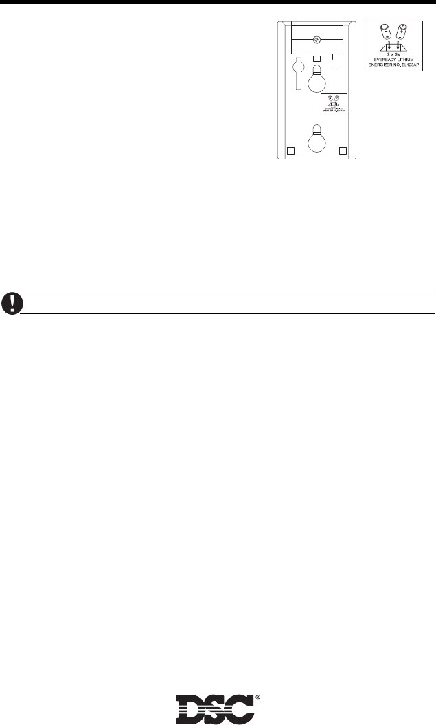
Battery Installation
• Use fresh batteries. Most batteries have a
“best before” date printed on their
packaging or on the batteries themselves.
Buy batteries that have a “best before”
date of two years or more from your
purchase date
• When disposing of used batteries, follow
the instructions and precautions printed
on the batteries. Many cities and
communities have collection sites or services for used household batteries.
Contact your municipal offices for information on the disposal of used
batteries
• Do not mix old and new batteries
• Remove the detector from its mounting plate
• Remove the battery cover by pushing down then up on the cover
• Ensure batteries are the proper orientation
• Replace the battery cover
Use only Energizer Lithium EL123AP batteries.
LIMITED WARRANTY
Digital Security Controls Ltd. warrants that for a period of twelve months from the date of purchase, the product shall be free
of defects in material and workmanship under normal use and that in fulfilment of any breach of such warranty, Digital Security
Controls Ltd. shall, at its option, repair or replace the defective equipment upon return of the equipment to its repair depot.
This warranty applies only to defects in parts and workmanship and not to damage incurred in shipping or handling, or damage
due to causes beyond control of Digital Security Controls Ltd. such as lightning, excessive voltage, mechanical shock, water
damage, or damage arising out of abuse, alteration or improper application of the equipment.
The foregoing warranty shall apply only to the original buyer, and is and shall be in lieu of any and all other warranties, whether
express or implied and of all other obligations or liabilities on the part of Digital Security Controls Ltd. This warranty contains
the entire warranty. Digital Security Controls Ltd. neither assumes, nor authorizes any other person purporting to act on its
behalf to modify or to change this warranty, nor to assume for it any other warranty or liability concerning this product.
In no event shall Digital Security Controls Ltd. be liable for any direct , indirect or consequential damages, loss of anticipated
profits, loss of time or any other losses incurred by the buyer in connection with the purchase, installation or operation or failure
of this product.
Warning:
Digital Security Controls Ltd. recommends that the entire system be completely tested on a regular basis. However,
despite frequent testing, and due to but not limited to, criminal tampering or electrical disruption, it is possible for this product
to fail to perform as expected.
FCC COMPLIANCE STATEMENT
CAUTION: Changes or modifications not expressly approved by Digital Security Controls Ltd. could void your authority to use this
equipment.
This equipment generates and uses radio frequency energy and if not installed and used properly, in strict accordance with the
manufacturer’s instructions, may cause interference to radio and television reception. It has been type tested and found to comply with
the limits for Class B device in accordance with the specifications in Subpart “B” of Part 15 of FCC Rules, which are designed to provide
reasonable protection against such interference in any residential installation. However, there is no guarantee that interference will not
occur in a particular installation. If this equipment does cause interference to television or radio reception, which can be determined by
turning the equipment off and on, the user is encouraged to try to correct the interference by one or more of the following measures:
•Re-orient the receiving antenna
•Relocate the alarm control with respect to the receiver
•Move the alarm control away from the receiver
•Connect the alarm control into a different outlet so that alarm control and receiver are on different circuits.
If necessary, the user should consult the dealer or an experienced radio/television technician for additional suggestions. The user may
find the following booklet prepared by the FCC helpful: “How to Identify and Resolve Radio/Television Interference Problems”. This
booklet is available from the U.S. Government Printing Office, Washington, D.C. 20402, Stock # 004-000-00345-4. • W A R N I N G •
Please refer to the System Installation Manual for information on
limitations regarding product use and function and information
on the limitations as to liability of the manufacturer.
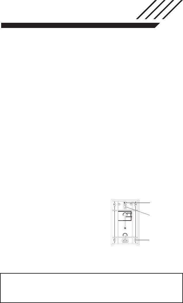
CORNER MOUNTING
KNOCKOUTS
ENSURE PROPER
ORIENTATION OF
BACKPLATE.
MOUNTING HOLE
KNOCKOUTS
Motion Detector Backplate
WLS904L
Wireless Motion Detector
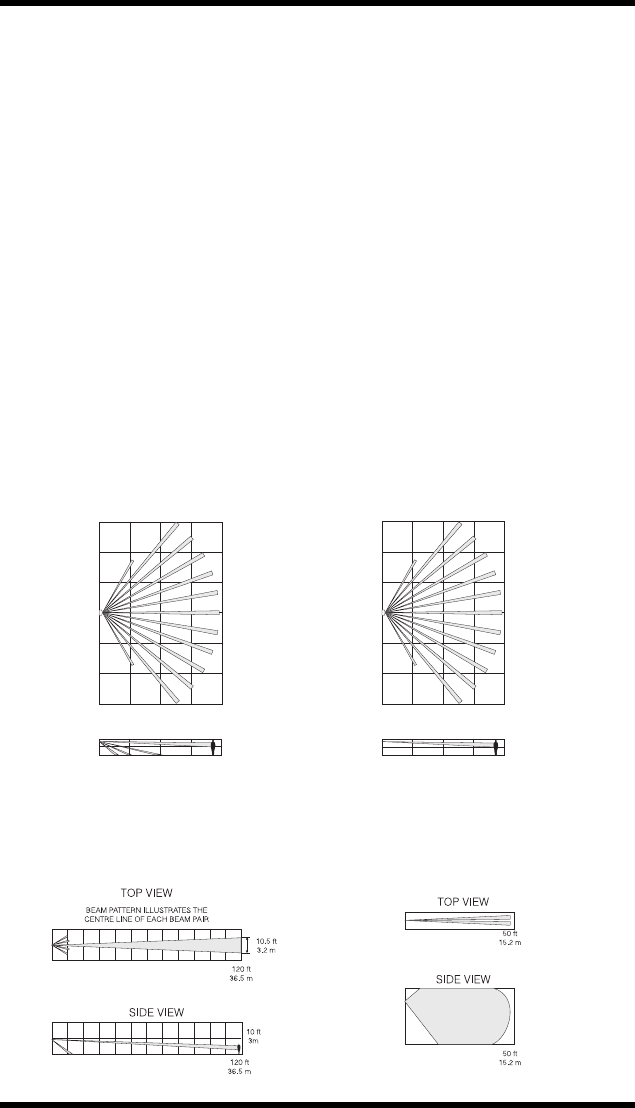
Changing Motion Detector Lenses
Each motion detector is supplied with the Wall-to-Wall lens; three additional
lenses are available for the WLS904L motion detector. The charts on this
page illustrate the range and coverage patterns of each lens.
To change the lens, first open the motion detector by removing the screw in
the bottom of the battery compartment. With the screw removed, pull the
back of the detector away from the front case.
NOTE: The coils and antenna on the motion detector circuit board are very
sensitive components precisely adjusted for maximum performance. Do
not touch the coils or antenna! Even minor distortions can affect the
performance of the motion detector.
Remove the lens holder by pressing down on the top of the holder and pulling
the holder away from the case. When installing the new lens, ensure the
grooved surface faces the interior of the case, and the notches on the lens face
the bottom of the case. Replace the lens holder by snapping it back into place.
Reassemble the motion detector by first engaging the clips on the bottom of
the case. Close the case and then secure the case with the screw in the
bottom of the battery compartment.
Wall-to-Wall Lens Pet Alley
DSC Model BV-L1 DSC Model BV-L4
Range: 50' L × 60' W (16 m × 18 m) Range: 50' L × 60' W (16 m × 18 m)
50 ft
15.2 m
0ft
0m
15 ft
4.6 m
15 ft
4.6 m
30 ft
9.1 m
30 ft
9.1 m
50 ft
15.2 m
TOP VIEW
SIDE VIEW
50 ft
15.2 m
0ft
0m
15 ft
4.6 m
15 ft
4.6 m
30 ft
9.1 m
30 ft
9.1 m
50 ft
15.2 m
TOP VIEW
SIDE VIEW
Corridor Lens Curtain Lens
DSC Model BV-L2 DSC Model BV-L3
Range: 120' L × 10.5' W (36.5 m × 3 m) Range: 50' L × 4.4' W (16 m × 1.3 m)
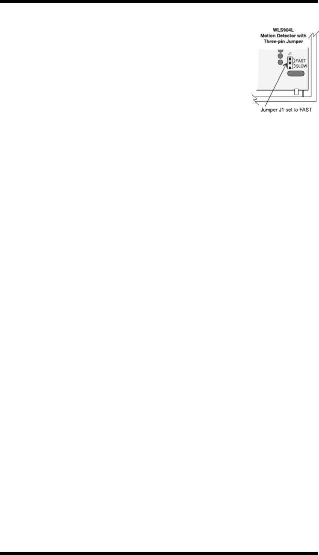
Changing the Motion Detector Sensitivity
The motion detector features Fast and Slow detection
modes, which are set on jumper J1. Jumper J1 is set at the
factory for the Fast detection mode. In a normal operating
environment, this setting provides the best detection.
In certain environments where rapid air movement, heaters
and other variables present problems, use Slow detection
mode to stabilize the detection.
Jumper “J1” is located in the bottom right corner of the
circuit board. To change the setting from Fast to Slow,
move the jumper over one pin, as shown in the diagram.
High Traffic Shutdown Mode
To prolong battery life, the motion detector uses a feature called High Traffic
Shutdown. When motion is detected, the device will transmit to the receiver
and will then shut down for three minutes. If motion is detected again during
the shutdown time, the unit will not transmit the event to the receiver. The
detector will thus remain in the shutdown mode until three minutes after the
first motion detected was transmitted. The detector will transmit detected
motion every three minutes.
The High Traffic Shutdown Mode affects testing the motion detector in two ways:
When performing the module placement test, the unit must be tampered by
removing the unit from the backplate and replacing it. The placement test
cannot be performed by creating motion in front of the device.
When performing a system test, the unit must be left idle for three minutes
before testing can be performed. Once three minutes has passed, create
motion in front of the detector to see if the device is both detecting motion
and transmitting to the receiver.
Motion Detector Transmission Delay
A motion detector transmission is always delayed by five seconds. This is
necessary to prevent false alarms caused by a motion sensor transmitting
before a delay zone has a chance to report. This five-second delay cannot
be altered or disabled.
Walk Test Mode
The motion detector has a walk test mode which will activate an LED for
testing purposes. During normal operation, the LED will not turn on.
To put the detector in walk test mode, create a tamper by removing the
detector from its backplate and then replacing it. Each time the detector
senses motion, it will turn on the red LED. Five seconds after motion is
detected, the detector will send a signal to the receiver, and the LED will
flash rapidly 5 times. The detector will be in walk test mode until it has sent
10 transmissions.
NOTE: The Walk Test Mode will override the High Traffic Shutdown Mode.
Changing Motion Detector Lenses
Each motion detector is supplied with the Wall-to-Wall lens; three additional
lenses are available for the WLS904L motion detector. The charts on this
page illustrate the range and coverage patterns of each lens.
To change the lens, first open the motion detector by removing the screw in
the bottom of the battery compartment. With the screw removed, pull the
back of the detector away from the front case.
NOTE: The coils and antenna on the motion detector circuit board are very
sensitive components precisely adjusted for maximum performance. Do
not touch the coils or antenna! Even minor distortions can affect the
performance of the motion detector.
Remove the lens holder by pressing down on the top of the holder and pulling
the holder away from the case. When installing the new lens, ensure the
grooved surface faces the interior of the case, and the notches on the lens face
the bottom of the case. Replace the lens holder by snapping it back into place.
Reassemble the motion detector by first engaging the clips on the bottom of
the case. Close the case and then secure the case with the screw in the
bottom of the battery compartment.
Wall-to-Wall Lens Pet Alley
DSC Model BV-L1 DSC Model BV-L4
Range: 50' L × 60' W (16 m × 18 m) Range: 50' L × 60' W (16 m × 18 m)
50 ft
15.2 m
0ft
0m
15 ft
4.6 m
15 ft
4.6 m
30 ft
9.1 m
30 ft
9.1 m
50 ft
15.2 m
TOP VIEW
SIDE VIEW
50 ft
15.2 m
0ft
0m
15 ft
4.6 m
15 ft
4.6 m
30 ft
9.1 m
30 ft
9.1 m
50 ft
15.2 m
TOP VIEW
SIDE VIEW
Corridor Lens Curtain Lens
DSC Model BV-L2 DSC Model BV-L3
Range: 120' L × 10.5' W (36.5 m × 3 m) Range: 50' L × 4.4' W (16 m × 1.3 m)
Changing the Motion Detector Sensitivity
The motion detector features Fast and Slow detection
modes, which are set on jumper J1. Jumper J1 is set at the
factory for the Fast detection mode. In a normal operating
environment, this setting provides the best detection.
In certain environments where rapid air movement, heaters
and other variables present problems, use Slow detection
mode to stabilize the detection.
Jumper “J1” is located in the bottom right corner of the
circuit board. To change the setting from Fast to Slow,
move the jumper over one pin, as shown in the diagram.
High Traffic Shutdown Mode
To prolong battery life, the motion detector uses a feature called High Traffic
Shutdown. When motion is detected, the device will transmit to the receiver
and will then shut down for three minutes. If motion is detected again during
the shutdown time, the unit will not transmit the event to the receiver. The
detector will thus remain in the shutdown mode until three minutes after the
first motion detected was transmitted. The detector will transmit detected
motion every three minutes.
The High Traffic Shutdown Mode affects testing the motion detector in two ways:
When performing the module placement test, the unit must be tampered by
removing the unit from the backplate and replacing it. The placement test
cannot be performed by creating motion in front of the device.
When performing a system test, the unit must be left idle for three minutes
before testing can be performed. Once three minutes has passed, create
motion in front of the detector to see if the device is both detecting motion
and transmitting to the receiver.
Motion Detector Transmission Delay
A motion detector transmission is always delayed by five seconds. This is
necessary to prevent false alarms caused by a motion sensor transmitting
before a delay zone has a chance to report. This five-second delay cannot
be altered or disabled.
Walk Test Mode
The motion detector has a walk test mode which will activate an LED for
testing purposes. During normal operation, the LED will not turn on.
To put the detector in walk test mode, create a tamper by removing the
detector from its backplate and then replacing it. Each time the detector
senses motion, it will turn on the red LED. Five seconds after motion is
detected, the detector will send a signal to the receiver, and the LED will
flash rapidly 5 times. The detector will be in walk test mode until it has sent
10 transmissions.
NOTE: The Walk Test Mode will override the High Traffic Shutdown Mode.
Each WLS904L motion detector should be located so that it provides
optimal coverage of the intended area. Refer to Changing Motion Detector
Lenses below for information on the four lenses available for the WLS904L
Motion Detector. When locating motion detectors, observe the following:
• For the Wall-to-Wall, Corridor and Curtain Lenses, the Mounting Height
should be 6-10 ft./ 2-3 m from the floor. The nominal mounting height is
7.5 ft./ 2.3 m.
• For the Pet Alley Lens only, the Mounting Height should be 4-5 ft./1.2-1.5m
from the floor.
• Do not aim the detector at reflective surfaces such as mirrors or
windows. This may distort the coverage pattern or reflect sunlight
directly onto the detector. Avoid locations where the detector may be
exposed to direct or reflected sunlight.
• Avoid locations that are subject to direct air flow, such as near an air duct outlet.
• Do not locate the detector near sources of steam or oil vapor, such as
a stove or fryer.
• Do not obscure the Detector’s coverage pattern with large objects within
the detection area. If you can’t see the detector, it can’t see you.
• For indoor use only
• Dead zone 6”/15 cm
NOTE: No detector should be mounted without first performing a
module placement test to determine that it is in range of the
wireless receiver. See the Placement Test instructions in the
Instruction Sheet for your receiver, or in the installation manual for
your system.
When a location has been determined,
remove the plastic from the mounting
holes and locate the backplate on the
wall and mark screw locations. It is
suggested that wall anchors be used for
all screw locations. Secure the backplate
to the wall, and then secure the enrolled
Detector to its backplate.
©2000 Digital Security Controls Ltd.
Printed in Canada 29005255 R001
INSTALLATION INSTRUCTIONSINSTALLATION INSTRUCTIONS
INSTALLATION INSTRUCTIONSINSTALLATION INSTRUCTIONS
INSTALLATION INSTRUCTIONS
Battery Installation
• Use fresh batteries. Most batteries have a
“best before” date printed on their
packaging or on the batteries themselves.
Buy batteries that have a “best before”
date of two years or more from your
purchase date
• When disposing of used batteries, follow
the instructions and precautions printed
on the batteries. Many cities and
communities have collection sites or services for used household batteries.
Contact your municipal offices for information on the disposal of used
batteries
• Do not mix old and new batteries
• Remove the detector from its mounting plate
• Remove the battery cover by pushing down then up on the cover
• Ensure batteries are the proper orientation
• Replace the battery cover
Use only Energizer Lithium EL123AP batteries.
LIMITED WARRANTY
Digital Security Controls Ltd. warrants that for a period of twelve months from the date of purchase, the product shall be free
of defects in material and workmanship under normal use and that in fulfilment of any breach of such warranty, Digital Security
Controls Ltd. shall, at its option, repair or replace the defective equipment upon return of the equipment to its repair depot.
This warranty applies only to defects in parts and workmanship and not to damage incurred in shipping or handling, or damage
due to causes beyond control of Digital Security Controls Ltd. such as lightning, excessive voltage, mechanical shock, water
damage, or damage arising out of abuse, alteration or improper application of the equipment.
The foregoing warranty shall apply only to the original buyer, and is and shall be in lieu of any and all other warranties, whether
express or implied and of all other obligations or liabilities on the part of Digital Security Controls Ltd. This warranty contains
the entire warranty. Digital Security Controls Ltd. neither assumes, nor authorizes any other person purporting to act on its
behalf to modify or to change this warranty, nor to assume for it any other warranty or liability concerning this product.
In no event shall Digital Security Controls Ltd. be liable for any direct , indirect or consequential damages, loss of anticipated
profits, loss of time or any other losses incurred by the buyer in connection with the purchase, installation or operation or failure
of this product.
Warning:
Digital Security Controls Ltd. recommends that the entire system be completely tested on a regular basis. However,
despite frequent testing, and due to but not limited to, criminal tampering or electrical disruption, it is possible for this product
to fail to perform as expected.
FCC COMPLIANCE STATEMENT
CAUTION: Changes or modifications not expressly approved by Digital Security Controls Ltd. could void your authority to use this
equipment.
This equipment generates and uses radio frequency energy and if not installed and used properly, in strict accordance with the
manufacturer’s instructions, may cause interference to radio and television reception. It has been type tested and found to comply with
the limits for Class B device in accordance with the specifications in Subpart “B” of Part 15 of FCC Rules, which are designed to provide
reasonable protection against such interference in any residential installation. However, there is no guarantee that interference will not
occur in a particular installation. If this equipment does cause interference to television or radio reception, which can be determined by
turning the equipment off and on, the user is encouraged to try to correct the interference by one or more of the following measures:
•Re-orient the receiving antenna
•Relocate the alarm control with respect to the receiver
•Move the alarm control away from the receiver
•Connect the alarm control into a different outlet so that alarm control and receiver are on different circuits.
If necessary, the user should consult the dealer or an experienced radio/television technician for additional suggestions. The user may
find the following booklet prepared by the FCC helpful: “How to Identify and Resolve Radio/Television Interference Problems”. This
booklet is available from the U.S. Government Printing Office, Washington, D.C. 20402, Stock # 004-000-00345-4. • W A R N I N G •
Please refer to the System Installation Manual for information on
limitations regarding product use and function and information
on the limitations as to liability of the manufacturer.
CORNER MOUNTING
KNOCKOUTS
ENSURE PROPER
ORIENTATION OF
BACKPLATE.
MOUNTING HOLE
KNOCKOUTS
Motion Detector Backplate
WLS904L
Wireless Motion Detector